WO2022014308A1 - 情報処理装置、情報処理方法および端末装置 - Google Patents
情報処理装置、情報処理方法および端末装置 Download PDFInfo
- Publication number
- WO2022014308A1 WO2022014308A1 PCT/JP2021/024269 JP2021024269W WO2022014308A1 WO 2022014308 A1 WO2022014308 A1 WO 2022014308A1 JP 2021024269 W JP2021024269 W JP 2021024269W WO 2022014308 A1 WO2022014308 A1 WO 2022014308A1
- Authority
- WO
- WIPO (PCT)
- Prior art keywords
- position information
- information
- information processing
- unit
- user
- Prior art date
- Legal status (The legal status is an assumption and is not a legal conclusion. Google has not performed a legal analysis and makes no representation as to the accuracy of the status listed.)
- Ceased
Links
Images






Classifications
-
- H—ELECTRICITY
- H04—ELECTRIC COMMUNICATION TECHNIQUE
- H04S—STEREOPHONIC SYSTEMS
- H04S7/00—Indicating arrangements; Control arrangements, e.g. balance control
- H04S7/30—Control circuits for electronic adaptation of the sound field
- H04S7/302—Electronic adaptation of stereophonic sound system to listener position or orientation
-
- H—ELECTRICITY
- H04—ELECTRIC COMMUNICATION TECHNIQUE
- H04S—STEREOPHONIC SYSTEMS
- H04S7/00—Indicating arrangements; Control arrangements, e.g. balance control
- H04S7/30—Control circuits for electronic adaptation of the sound field
- H04S7/301—Automatic calibration of stereophonic sound system, e.g. with test microphone
-
- H—ELECTRICITY
- H04—ELECTRIC COMMUNICATION TECHNIQUE
- H04S—STEREOPHONIC SYSTEMS
- H04S2400/00—Details of stereophonic systems covered by H04S but not provided for in its groups
- H04S2400/11—Positioning of individual sound objects, e.g. moving airplane, within a sound field
-
- H—ELECTRICITY
- H04—ELECTRIC COMMUNICATION TECHNIQUE
- H04S—STEREOPHONIC SYSTEMS
- H04S2420/00—Techniques used stereophonic systems covered by H04S but not provided for in its groups
- H04S2420/01—Enhancing the perception of the sound image or of the spatial distribution using head related transfer functions [HRTF's] or equivalents thereof, e.g. interaural time difference [ITD] or interaural level difference [ILD]
Definitions
- This disclosure relates to an information processing device, an information processing method, and a terminal device.
- HRTF head-related transfer function
- HRTFs vary greatly from individual to individual, it is desirable to use HRTFs for each individual when using them. Therefore, for example, a technique for estimating an HRTF based on an image of a user's pinna is known.
- a correction unit that renders audio data including position information of a sound object to a plurality of virtual speakers virtually arranged in space, and a virtual position of the virtual speaker in the space.
- the correction unit includes one position information and an acquisition unit for acquiring the second position information regarding the position of the virtual speaker in the space perceived by the user, and the correction unit has the plurality of the correction units based on the second position information.
- An information processing apparatus is provided that corrects the first position information of at least one of the virtual speakers of the above.
- FIG. 1 It is a figure which shows the structural example of the information processing system which concerns on embodiment. It is a figure which shows the outline of the acoustic space which concerns on embodiment. It is a figure which shows the outline of the acoustic space which concerns on embodiment. It is a block diagram which shows the structural example of the information processing system which concerns on embodiment. It is a figure which shows an example of the determination process of the perceptual position which concerns on embodiment. It is a figure which shows the outline of the function of the information processing apparatus which concerns on embodiment. It is a figure which shows the outline of the function of the information processing apparatus which concerns on embodiment. It is a figure which shows an example of the display screen of the terminal apparatus which concerns on embodiment.
- the HRTF expresses the change in sound caused by peripheral objects including the shape of the human pinna and the head as a transfer function.
- measurement data for obtaining an HRTF is acquired by measuring an acoustic signal (audio signal) for measurement using a microphone or a dummy head microphone worn by a human in the auricle.
- HRTFs used in technologies such as 3D sound are often calculated using measurement data acquired by a dummy head microphone or the like, an average value of measurement data acquired from a large number of human beings, or the like.
- the HRTF varies greatly from individual to individual, it is desirable to use the user's own HRTF in order to realize a more effective sound effect.
- Patent Document 1 a technique for estimating an HRTF based on an image of a user's pinna is known (Patent Document 1).
- Patent Document 1 a technique for estimating an HRTF based on an image of a user's pinna is known (Patent Document 1).
- Patent Document 1 a technique for estimating an HRTF based on an image of a user's pinna is known (Patent Document 1).
- the sound quality may be impaired when the sound image is reproduced, so that there is room for further improvement of usability.
- an example of a three-dimensional acoustic panning method in which 3D-Audio object data (for example, metadata of an acoustic signal or position information of a sound object) is applied to a plurality of virtual speakers whose positions are predetermined.
- 3D-Audio object data for example, metadata of an acoustic signal or position information of a sound object
- VBAP Vector Based Applied Panning
- the reproduction space is divided into a triangular region composed of three speakers, and the sound source signal is distributed to each speaker by a weighting coefficient to perform amplitude panning.
- a pre-held HRTF is applied to the speaker signal, and each virtual speaker composed of L (Left: L) and R (Right: R) signals is applied.
- a technique for obtaining a headphone signal headphone reproduction signal
- the headphone signal for each virtual speaker is added (summed) for each of the L and R signals to obtain a headphone signal.
- the 3D-Audio can be reproduced by the headphones, for example, by obtaining the signal reproduced from the headphones by using the above technique.
- the sound image may not be localized at a predetermined position, and the sound quality may be impaired. Therefore, there is room for further improvement of usability.
- FIG. 1 is a diagram showing a configuration example of the information processing system 1.
- the information processing system 1 includes an information processing device 10, headphones 20, and a terminal device 30.
- Various devices can be connected to the information processing device 10.
- the headphone 20 and the terminal device 30 are connected to the information processing device 10, and information is linked between the devices.
- the information processing device 10, the headphone 20, and the terminal device 30 are connected to an information communication network by wireless or wired communication so that information / data communication can be performed with each other and can operate in cooperation with each other.
- the information communication network may be composed of an Internet, a home network, an IoT (Internet of Things) network, a P2P (Peer-to-Peer) network, a proximity communication mesh network, and the like. Radio can utilize technologies based on mobile communication standards such as Wi-Fi, Bluetooth®, or 4G and 5G. For wired communication, power line communication technology such as Ethernet (registered trademark) or PLC (Power Line Communications) can be used.
- Ethernet registered trademark
- PLC Power Line Communications
- the information processing device 10, the headphones 20, and the terminal device 30 may be separately provided as a plurality of computer hardware devices on a so-called on-premises (On-Premise), an edge server, or the cloud, or the information processing device. 10.
- the functions of any plurality of devices among the headphones 20 and the terminal device 30 may be provided as the same device.
- the information processing device 10, the headphones 20, and the terminal device 30 may be provided as a device in which the information processing device 10 and the headphones 20 function integrally and communicate with the terminal device 30.
- the information processing device 10 and the terminal device 30 may be realized so that the information processing device 10 and the terminal device 30 function together in the same terminal such as a smart phone.
- a user interface including a Graphical Interface: GUI
- GUI Graphical Interface
- Information and data communication with the information processing device 10, the headphones 20, and the terminal device 30 is enabled via software (composed of a computer program (hereinafter, also referred to as a program)).
- the information processing device 10 is an information processing device that performs a process of rendering audio data including position information of a sound object to a plurality of virtual speakers virtually arranged in space. Further, the information processing apparatus 10 corrects the position information regarding the virtual position of the virtual speaker in the space. As a result, the information processing apparatus 10 can localize the sound image of the sound object at the intended position, so that the possibility that the sound quality is impaired can be reduced. As a result, the information processing apparatus 10 can promote further improvement in usability.
- the information processing device 10 also has a function of controlling the overall operation of the information processing system 1. For example, the information processing device 10 controls the overall operation of the information processing system 1 based on the information linked between the devices. Specifically, the information processing device 10 corrects the position information of the virtual speaker based on the information transmitted from the terminal device 30.
- the information processing device 10 is realized by a PC (Personal computer), a server (Server), or the like.
- the information processing device 10 is not limited to a PC, a server, or the like.
- the information processing device 10 may be a computer hardware device such as a PC or a server that implements the function of the information processing device 10 as an application.
- the information processing device 10 may be any device as long as the processing in the embodiment can be realized. Further, the information processing device 10 may be a device such as a smart phone, a tablet terminal, a notebook PC, a desktop PC, a mobile phone, or a PDA. Hereinafter, in the embodiment, the information processing device 10 and the terminal device 30 may be realized by the same terminal such as a smart phone.
- the headphone 20 is a headphone used by the user to listen to the sound.
- the headphone 20 is a headphone having a member that is in contact with the user's ear and can provide sound.
- the headphone 20 is a headphone having a member that can separate the space including the eardrum of the user and the outside world.
- the headphone 20 outputs two channels of headphone signals, one for L and the other for R.
- the headphone 20 is not limited to headphones, and may be any device as long as it can provide sound.
- the headphones 20 may be earphones or the like.
- Terminal device 30 is an information processing device used by the user.
- the terminal device 30 may be any device as long as the processing in the embodiment can be realized. Further, the terminal device 30 may be a device such as a smart phone, a tablet terminal, a notebook PC, a desktop PC, a mobile phone, or a PDA.
- the embodiment will be described using a virtual speaker, but the present invention is not limited to the virtual speaker, and any virtual speaker may be used as long as it provides virtual sound.
- first position information the position information regarding the virtual position of the virtual speaker in the space
- second position information the position information regarding the position of the virtual speaker perceived by the user in space
- the HRTF according to the embodiment is not limited to the HRTF based on the measurement data actually measured as the user's HRTF.
- the HRTF according to the embodiment may be an average HRTF based on the HRTFs of a plurality of users as the HRTF of the target user (target user).
- the HRTF according to the embodiment may be an HRTF estimated from imaging information such as an ear image.
- the HRTF will be described, but the HRTF is not limited to the BRIR (Binaural Room Impulse Response: BRIR).
- the HRTF according to the embodiment may be any as long as the transmission characteristic of the sound reaching the user's ear from a predetermined position in the space is measured as an impulse response.
- FIG. 2 is a diagram showing an outline of an acoustic space according to an embodiment.
- three virtual speakers (speaker SP11 to speaker SP13) are used to provide an acoustic space to the user U11.
- the user U11 reproduces the acoustic signal from the speaker SP11 to the speaker SP13 on the headphone HP11.
- the speaker SP 11 to the speaker SP 13 are located at positions A to C, respectively.
- the positions A to C are the first position information of each virtual speaker.
- the data TF 11 to the data TF 13 indicate the HRTF from the position A to the position C, respectively.
- the data TF 11 to the data TF 13 show characteristics that imitate the transmission characteristics from the predetermined positions A to C to the eardrum of the user U11, respectively.
- the HRTF may be held for each position A to C.
- This HRTF is, for example, an impulse response for L and R of headphones and the like.
- a two channel acoustic signal may be obtained.
- the signal for L among the acoustic signals of the two channels is the result of convolution processing of the acoustic signal of one channel of the input by the impulse response for L of the HRTF.
- the signal for R is the result of convolution processing with the impulse response for R.
- the HRTF has a characteristic that imitates the transmission characteristic from a predetermined position to the human eardrum
- the user U11 has the sound localized at the position A, for example. Perceive.
- FIG. 3 is a diagram showing an outline of the acoustic space according to the embodiment.
- FIG. 2 shows a case where the sound is localized at a predetermined position
- FIG. 3 shows a case where the sound is not localized at a predetermined position.
- the speaker SP11 will be described as a virtual speaker to be rendered (hereinafter, appropriately referred to as a “reproduction target virtual speaker”). Since the HRTF depends on the shape of the human head, the shape of the auricle, the shape of the ear canal, etc., the HRTF held in advance may not match the HRTF of the user.
- FIG. 2 shows a case where the sound is localized at a predetermined position
- FIG. 3 shows a case where the sound is not localized at a predetermined position.
- the speaker SP11 will be described as a virtual speaker to be rendered (hereinafter, appropriately referred to as a “reproduction target virtual speaker”). Since the HRTF depends on the shape of the human head, the shape of the auricle,
- the sound image is localized at a position A prime position different from the position A, for example.
- This position A prime is the second position information of the speaker SP1 perceived by the user.
- the user U11 perceives the speaker SP11 at the position A prime position instead of the original position A.
- the sound object TB11 having the position information of the center of gravity position ⁇ of the triangular region of the position A to the position C is rendered and the headphone signal is obtained by using the prior art, the perceived position of the position A of the user U11 is determined. Since it is the position A prime, the perceived position of the sound object TB11 may also be the position ⁇ prime instead of the position ⁇ .
- the perceived position is the position ⁇ prime because the user perceives the position A as the position A prime after the gain of each virtual speaker is the same by VBAP. Therefore, since the sound object TB11 may not be perceived at the originally intended position, the sound quality may be impaired.
- FIG. 4 is a block diagram showing a functional configuration example of the information processing system 1 according to the embodiment.
- the information processing apparatus 10 includes a communication unit 100 and a control unit 110.
- the information processing device 10 has at least a control unit 110.
- the communication unit 100 has a function of communicating with an external device. For example, the communication unit 100 outputs information received from the external device to the control unit 110 in communication with the external device. Specifically, the communication unit 100 outputs the information received from the terminal device 30 to the control unit 110. For example, the communication unit 100 outputs the second position information of the virtual speaker to the control unit 110.
- the communication unit 100 transmits information input from the control unit 110 to the external device in communication with the external device. Specifically, the communication unit 100 transmits information regarding acquisition of information regarding the perceived position of the virtual speaker input from the control unit 110 to the terminal device 30.
- the communication unit 100 is composed of a hardware circuit (communication processor, etc.), and is configured to perform processing by a computer program operating on the hardware circuit or another processing device (CPU, etc.) that controls the hardware circuit. can do.
- Control unit 110 has a function of controlling the operation of the information processing apparatus 10. For example, the control unit 110 performs a process for correcting the first position information based on the second position information.
- the control unit 110 includes an acquisition unit 111, a processing unit 112, and an output unit 113, as shown in FIG.
- the control unit 110 is composed of a processor such as a CPU, and is designed to read software (computer program) that realizes each function of the acquisition unit 111, the processing unit 112, and the output unit 113 from the storage unit 120 and perform processing. You may. Further, one or more of the acquisition unit 111, the processing unit 112, and the output unit 113 are configured by a hardware circuit (processor or the like) different from the control unit 110, and operate on another hardware circuit or the control unit 110. It can be configured to be controlled by a computer program that does.
- the acquisition unit 111 has a function of acquiring the first position information of the virtual speaker. For example, the acquisition unit 111 acquires the first position information of a plurality of virtual speakers. Further, the acquisition unit 111 acquires the second position information of the virtual speaker perceived by the user. For example, the acquisition unit 111 acquires the second position information of the virtual speaker to be reproduced. Further, for example, the acquisition unit 111 acquires the second position information of the virtual speaker based on the input information input by the user during the reproduction of the output signal (for example, the headphone signal) from the audio output unit such as headphones.
- the output signal for example, the headphone signal
- the acquisition unit 111 acquires the user's HRTF data held at the position of the virtual speaker. For example, the acquisition unit 111 acquires HRTF data obtained by measuring the transmission characteristics of the sound reaching the user's ear from each virtual speaker as an impulse response.
- the acquisition unit 111 acquires the position information of one or more sound objects. It is assumed that the sound object is located within a predetermined range configured based on a plurality of first position information. Further, the acquisition unit 111 acquires information regarding the perceived position of the sound object.
- the processing unit 112 has a function for controlling the processing of the information processing apparatus 10. As shown in FIG. 4, the processing unit 112 has a determination unit 1121, a correction unit 1122, and a generation unit 1123.
- the determination unit 1121, the correction unit 1122, and the generation unit 1123 included in the processing unit 112 may be configured as modules of independent computer programs, or may have a plurality of functions in one cohesive computer program. It may be configured as a module.
- the determination unit 1121 has a function of determining the second position information.
- the determination of the second position information will be described by taking the following two methods as examples.
- the determination unit 1121 determines the second position information based on the line-of-sight information that is taken while pointing the terminal device 30 toward the sound object that the user perceives. good. Specifically, the determination unit 1121 has the terminal device 30 in a direction in which the sound reproduced by the headphones 20 is localized while the image pickup member such as a camera is directed toward the user's face by the terminal device 30 having the image pickup function. May determine the second position information. In this case, the determination unit 1121 may determine the second position information by calculating in which direction the user holds the terminal device 30 from the angle of the user's face.
- the determination unit 1121 may determine the second position information based on the geomagnetic information detected by the terminal device 30 while pointing the terminal device 30 having a rod-shaped shape toward the sound object perceived by the user. Specifically, the determination unit 1121 may determine the second position information by holding the rod-shaped terminal device 30 on which the geomagnetic sensor is mounted in the direction in which the sound reproduced by the headphones 20 is localized. In this case, the determination unit 1121 may determine the second position information by calculating the sensor value of the geomagnetic sensor. In this way, the determination unit 1121 may determine the second position information based on the sensor information of the terminal device 30.
- the determination unit 1121 may determine the second position information based on a method such as GUI (Graphical User Interface) software that can specify the position intended by the user.
- GUI Graphic User Interface
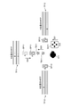
- FIG. 5 shows an example of processing for determining the second position information using GUI software.
- FIG. 5A shows a display screen of the terminal device 30 when the GUI software is started.
- the position information of the user U11 and the first position information of the virtual speaker (speaker SP11 to speaker SP13) in which the HRTF is predetermined are three-dimensionally drawn and displayed.
- the user U11 can appropriately grasp the position of the virtual speaker by changing the angle variously.
- the speaker SP11 is used as a reproduction target virtual speaker.
- the virtual speaker to be reproduced is represented by a thick circle “ ⁇ ” that can be moved on the screen.
- the terminal device 30 transmits the operation information to the information processing device 10.
- the information processing device 10 transmits a signal in which the HRTF at the position of the virtual speaker to be reproduced is convoluted into an acoustic signal such as white noise to the headphones 20. Then, the headphones 20 reproduce based on the signal received from the information processing apparatus 10.
- FIG. 5B shows a display screen of the terminal device 30 when the user U11 operates (for example, moves by dragging or tapping) the position perceived by the reproduced sound from the position A to the position A prime.
- the dotted circle “ ⁇ ” shown at the position A indicates the position of the speaker SP 11 before the operation.
- the solid circle “ ⁇ ” shown in the position A prime indicates the position after the operation of the speaker SP11.
- FIG. 5C shows a display screen of the terminal device 30 when the user U11 operates the command BB12.
- the virtual speaker to be reproduced is switched to a different speaker by the operation of the command BB12 of the user U11.
- the virtual speaker to be reproduced is switched from the speaker SP11 to the speaker SP12.
- the thick circle " ⁇ " that can be moved on the screen is a circle indicated from the position of the speaker SP11 to the position of the speaker SP12.
- the same processing as that of the speaker SP11 is performed.
- the determination unit 1121 is second-ordered by the user U11 manipulating the position perceived by the user U11 with the signal convoluted by the HRTF at each position for all the virtual speakers. Determine location information.
- the perceived position of the sound object TB11 becomes the position ⁇ prime.
- the perceived position of the sound object TB11 may be the position ⁇ .
- the perceived position is the position ⁇ because the gain of the virtual speaker located at the position A prime is larger than the gain of the virtual speaker at the position B and the position C. In this way, when the virtual speaker located at the position A is moved to the position A prime, the sound object TB11 located at the position ⁇ prime moves to the position ⁇ .
- the determination unit 1121 may determine the second position information by having the user adjust the position where the sound object TB11 moves to the position ⁇ by using GUI software or the like.
- the determination unit 1121 may determine the second position information by manually moving the virtual speaker by the user (for example, manually inputting). Hereinafter, it will be described with reference to FIGS. 6 to 8.
- FIG. 6 is a diagram showing an outline of the functions of the information processing apparatus 10 according to the embodiment. The same description as in FIGS. 2 and 3 will be omitted as appropriate.
- the user U11 inputs downward operation information using the member GU11 (for example, a screen or a device) (S11).
- the speaker SP11 moves from the position A to the position A prime so as to match the input of the user U11 (S12).
- the perceived position of the sound object TB11 moves from the position ⁇ prime to the position ⁇ according to the movement of the speaker SP11 (S13).
- the member GU 11 may be, for example, a perceived position adjustment button for adjusting the perceived position of the sound object TB11.
- the determination unit 1121 may determine the second position information based on the operation of the GUI of the user and the operation of moving the first position information to the second position information. As described above, the determination unit 1121 may determine the second position information based on the input information input by the user during the reproduction of the output signal.
- the perceived position of the sound object TB11 moves in the direction opposite to that of the speaker SP11, it may be difficult for the user U11 to adjust.
- FIG. 7 is a diagram showing an outline of the functions of the information processing apparatus 10 according to the embodiment.
- FIG. 7 is a modification of FIG. The same description as in FIG. 6 will be omitted as appropriate.
- the user U11 inputs upward operation information using the member GU11 (S21).
- the speaker SP11 moves from the position A to the position A prime in the direction opposite to the input of the user U11 (S22).
- step S23 is the same as step S13.
- the perceived position of the sound object TB11 moves from the position ⁇ prime to the position ⁇ so as to match the input of the user U11.
- FIG. 7 is a diagram showing an outline of the functions of the information processing apparatus 10 according to the embodiment.
- FIG. 7 is a modification of FIG. The same description as in FIG. 6 will be omitted as appropriate.
- the user U11 inputs upward operation information using the member GU11 (S21).
- the speaker SP11 moves from the position A to the position A prime in the direction opposite to the input of the user
- FIG. 8 shows a display screen of the terminal device 30 when the GUI software is started. The same description as in FIG. 5 will be omitted as appropriate.
- the position information of the user U11 is displayed.
- a circle “ ⁇ ” is displayed at a position inside the triangle composed of the first position information (positions A to C) of the virtual speakers (speakers SP11 to SP13) in which the HRTF is predetermined.
- FIG. 8 shows a case where the reference numerals of positions A to C are displayed for convenience of explanation, but it is not necessary to actually display them.
- the headphones 20 reproduce an acoustic signal such as white noise and a signal generated based on the position information indicated by the circle “ ⁇ ”.
- the user U11 adjusts using the member GU11 so that the position perceived by the sound reproduced by the headphone 20 is the position indicated by the circle “ ⁇ ”.
- the determination unit 1121 determines the second position information based on such adjustment by the user U11.
- a circle " ⁇ " is placed inside the triangle formed based on the first position information of a different virtual speaker whose apex is not the apex of the triangle composed of the positions A to C. Is displayed.
- the same processing as in the case where the circle " ⁇ " is displayed at the position inside the triangle composed of the positions A to C is performed.
- the determination unit 1121 may perform processing by using a method in which conventional techniques are appropriately combined.
- the correction unit 1122 has a function of rendering audio data including the position information of a sound object to a plurality of virtual speakers virtually arranged in space. Further, the correction unit 1122 corrects the first position information of at least one of the plurality of virtual speakers based on the second position information. Alternatively, the correction unit 1122 corrects the first position information of at least one of the plurality of virtual speakers based on the difference between the first position information and the second position information. For example, the correction unit 1122 corrects the first position information based on the second position information determined by the determination unit 1121. Further, for example, the correction unit 1122 corrects the first position information so that the perceived position of the sound object perceived by the user becomes a predetermined position based on the position information of the sound object.
- the correction unit 1122 calculates the difference based on the comparison of the coordinate information indicating the position information. Further, for example, the correction unit 1122 corrects the first position information based on the distance information indicating the difference.
- the correction unit 1122 may correct the first position information so that the larger the difference between the first position information and the second position information, the larger the correction amount of the perceived position of the sound object. For example, the correction unit 1122 may correct the first position information based on a predetermined correction amount of the perceived position of the sound object according to the difference between the first position information and the second position information.
- the correction unit 1122 corrects the first position information of the virtual speaker to be reproduced based on the perceived position of the sound object included in the predetermined range configured based on the first position information of the plurality of virtual speakers. good.
- the correction unit 1122 corrects the first position information of the virtual speaker to be reproduced based on the perceived position of the sound object included in the range of the triangle configured based on the first position information of the three virtual speakers. You may.
- the generation unit 1123 has a function of generating sound for reproduction. For example, the generation unit 1123 generates the sound for reproduction by adding all the sounds of the plurality of virtual speakers.
- the generation unit 1123 generates an output signal for each voice output unit based on the user's HRTF from the speaker signal for each virtual speaker generated by the correction unit 1122. For example, the generation unit 1123 may generate an output signal for each audio output unit based on the HRTF estimated from the imaging information such as the user's ear image. Further, for example, the generation unit 1123 may generate an output signal for each audio output unit based on the average HRTF calculated from the HRTFs of a plurality of users.
- the generation unit 1123 generates a speaker signal by rendering with VBAP using the second position information as the first position information for each of the virtual speakers. Further, the generation unit 1123 applies the HRTF held in advance to the speaker signal for each of the virtual speakers to generate an output signal for each virtual speaker. Then, the generation unit 1123 generates an output signal by adding the output signals for each virtual speaker for each of the virtual speakers for each of the L and R signals.
- the output unit 113 has a function of outputting the correction result by the correction unit 1122.
- the output unit 113 provides information on the correction result to, for example, the terminal device 30 via the communication unit 100.
- the terminal device 30 receives the output information provided from the output unit 113, the terminal device 30 displays the output information via the output unit 320.
- the output unit 113 may provide control information for displaying the output information. Further, the output unit 113 may generate output information for displaying information on the correction result on the terminal device 30.
- the output unit 113 has a function of outputting the generation result by the generation unit 1123.
- the output unit 113 provides information on the generation result to, for example, the headphones 20 via the communication unit 100.
- the output unit 113 provides an output signal for each audio output unit. Specifically, an output signal obtained by adding a speaker signal for each virtual speaker to each of the L and R signals is provided.
- the headphone 20 receives the output information provided from the output unit 113, the headphone 20 outputs the output information via the output unit 220.
- the output unit 113 may provide control information for outputting the output information. Further, the output unit 113 may generate output information for outputting information regarding the generation result to the headphones 20.
- the storage unit 120 is realized by, for example, a RAM (Random Access Memory), a semiconductor memory element such as a flash memory, or a storage device such as a hard disk or an optical disk.
- the storage unit 120 has a function of storing computer programs and data (including one format of the program) related to processing in the information processing apparatus 10.
- FIG. 9 shows an example of the storage unit 120.
- the storage unit 120 shown in FIG. 9 stores the first position information of the virtual speaker.
- the storage unit 120 may have items such as "virtual speaker ID”, “user ID”, “virtual speaker position”, and "HRTF".
- “Virtual speaker ID” indicates identification information for identifying a virtual speaker.
- the "user ID” indicates identification information for identifying a user.
- the “virtual speaker position” indicates the first position information of the virtual speaker. In the example shown in FIG. 9, a case where conceptual information such as “virtual speaker position # 11" and “virtual speaker position # 12" is stored in the “virtual speaker position” is shown, but actually, coordinate information and others are shown. Information indicating the relative position of the virtual speaker may be stored.
- “HRTF” indicates a predetermined HRTF based on the first position information of the virtual speaker. In the example shown in FIG. 9, a case where conceptual information such as “HRTF # 11" and “HRTF # 12" is stored in “HRTF” is shown, but in reality, it was measured by a microphone or the like near the user's ear. HRTF data is stored.
- the headphone 20 includes a communication unit 200, a control unit 210, and an output unit 220.
- the communication unit 200 has a function of communicating with an external device.
- the communication unit 200 outputs information received from the external device to the control unit 210 in communication with the external device.
- the communication unit 200 outputs the information received from the information processing device 10 to the control unit 210.
- the communication unit 200 outputs information regarding acquisition of information regarding sound for reproduction to the control unit 210.
- the communication unit 200 outputs information regarding acquisition of an output signal for each voice output unit to the control unit 210.
- Control unit 210 has a function of controlling the operation of the headphones 20. For example, the control unit 210 performs a process for reproducing sound based on the information transmitted from the information processing device 10 via the communication unit 200. For example, the control unit 210 performs a process for outputting an output signal.
- Output unit 220 The output unit 220 is realized by a member such as a speaker that can output sound.
- the output unit 220 outputs sound.
- the output unit 220 outputs an output signal.
- Terminal device 30 As shown in FIG. 4, the terminal device 30 has a communication unit 300, a control unit 310, and an output unit 320.
- the communication unit 300 has a function of communicating with an external device. For example, the communication unit 300 outputs information received from the external device to the control unit 310 in communication with the external device. Specifically, the communication unit 300 outputs information regarding the correction result received from the information processing device 10 to the control unit 310.
- Control unit 310 has a function of controlling the overall operation of the terminal device 30. For example, the control unit 310 performs a process of controlling the output of information regarding the correction result. Further, for example, the control unit 310 performs a process for moving the reproduction target virtual speaker according to the operation by the user. Further, for example, the control unit 310 performs a process for moving the perceived position of the sound object perceived by the user according to the movement of the virtual speaker to be reproduced.
- the output unit 320 has a function of outputting information regarding the correction result.
- the output unit 320 outputs the output information provided by the output unit 113 via the communication unit 300.
- the output unit 320 displays output information on the display screen of the terminal device 30.
- the output unit 320 may output output information based on the control information provided by the output unit 113.
- the output unit 320 displays output information according to the operation by the user. For example, the output unit 320 displays information regarding the position information of the virtual speaker to be reproduced and the sound object.
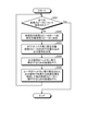
- FIG. 10 is a flowchart showing a processing flow in the information processing apparatus 10 according to the embodiment.
- the information processing device 10 acquires the first position information of the virtual speaker (S101). Further, the information processing apparatus 10 acquires the second position information of the virtual speaker (S102). Next, the information processing apparatus 10 calculates the difference between the first position information and the second position information (S103). For example, the information processing apparatus 10 calculates the difference based on the comparison of the coordinate information. Then, the information processing apparatus 10 corrects the first position information based on the calculated difference (S104). For example, the information processing apparatus 10 corrects the first position information so that the perceived position of the sound object perceived by the user becomes a predetermined position based on the position information of the sound object based on the calculated difference. do.
- FIG. 11 is a flowchart showing a processing flow in the information processing apparatus 10 according to the embodiment.
- the information processing apparatus 10 determines whether or not all the target virtual speakers have been designated by the user (S201). When it is determined that the information processing apparatus 10 has received the designation from the user for all the virtual speakers (S201; YES), the information processing apparatus 10 ends the information processing. Further, when the information processing apparatus 10 determines that the designation from the user is not accepted for all the virtual speakers (S201; NO), one of the undesignated virtual speakers is determined as the reproduction target virtual speaker (S202). ). Next, the information processing apparatus 10 convolves the HRTF of the virtual speaker to be reproduced with white noise or the like to generate an output signal (S203).
- the information processing apparatus 10 performs a process for reproducing the output signal with headphones or the like (S204).
- the information processing apparatus 10 designates a perceived position perceived by the output signal reproduced by the user through headphones or the like, and performs a process for shifting to another virtual speaker (S205).
- the information processing apparatus 10 performs a process for shifting to another virtual speaker when the user specifies a perceived position and accepts an operation such as the "Next" button. Then, the process returns to the process of step S201.
- FIG. 12 is a diagram showing an outline of the functions of the information processing apparatus 10 according to the modified example of the embodiment.
- the processing unit 112 has a determination unit 1121, a correction unit 1122, and a generation unit 1123.
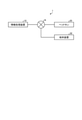
- the processing unit 112 may include a user perception acquisition unit 1124, a virtual speaker rendering unit 1125, an HRTF processing unit 1126, and an addition unit 1127 in addition to the configuration shown in FIG.
- the determination unit 1121, the correction unit 1122, the generation unit 1123, the user perception acquisition unit 1124, the virtual speaker rendering unit 1125, the HRTF processing unit 1126, and the addition unit 1127 of the processing unit 112 are as independent computer program modules. It may be configured, or a plurality of functions may be configured as a module of one cohesive computer program.
- the user perception acquisition unit 1124 acquires information (second position information) regarding the perceived position perceived by the user for the signal to which the held HRTF is applied for each of the M virtual speakers. Then, the user perception acquisition unit 1124 provides the acquired second position information to the virtual speaker rendering unit 1125 (S31).
- the virtual speaker rendering unit 1125 performs rendering processing with VBAP using the second position information acquired by the user perception acquisition unit 1124 as the first position information for each of the N sound objects, and N ⁇ M signals ( Hereinafter, a “virtual speaker rendering signal”) is generated as appropriate. Further, the virtual speaker rendering unit 1125 adds N virtual speaker rendering signals for each sound object for each of the virtual speakers. Then, the virtual speaker rendering unit 1125 provides the resulting M speaker signals to the HRTF processing unit 1126 (S32).
- the HRTF processing unit 1126 applies the HRTF held in advance to the speaker signal provided by the virtual speaker rendering unit 1125 for each of the virtual speakers. Then, the HRTF processing unit 1126 provides the output signals (for example, headphone signals) for each of the M virtual speakers as a result to the addition unit 1127 (S33).
- the addition unit 1127 adds the output signals for each virtual speaker provided by the HRTF processing unit 1126 for each of the L and R signals for each of the virtual speakers. Then, the addition unit 1127 performs a process for outputting an output signal (S34).
- FIG. 13 is a block diagram showing a hardware configuration example of the information processing apparatus according to the embodiment.
- the information processing device 900 shown in FIG. 13 can realize, for example, the information processing device 10, the headphones 20, and the terminal device 30 shown in FIG.
- the information processing by the information processing device 10, the headphones 20, and the terminal device 30 according to the embodiment is realized by the cooperation between the software (consisting of a computer program) and the hardware described below.
- the information processing apparatus 900 includes a CPU (Central Processing Unit) 901, a ROM (Read Only Memory) 902, and a RAM (Random Access Memory) 903.
- the information processing device 900 includes a host bus 904a, a bridge 904, an external bus 904b, an interface 905, an input device 906, an output device 907, a storage device 908, a drive 909, a connection port 910, and a communication device 911.
- the hardware configuration shown here is an example, and some of the components may be omitted. Further, the hardware configuration may further include components other than the components shown here.
- the CPU 901 functions as, for example, an arithmetic processing device or a control device, and controls all or a part of the operation of each component based on various computer programs recorded in the ROM 902, the RAM 903, or the storage device 908.
- the ROM 902 is a means for storing a program read into the CPU 901, data used for calculation, and the like.
- the RAM 903 temporarily or permanently stores data (a part of the program) such as a program read into the CPU 901 and various parameters that change appropriately when the program is executed. These are connected to each other by a host bus 904a composed of a CPU bus or the like.
- the CPU 901, ROM 902, and RAM 903 can, for example, realize the functions of the control unit 110, the control unit 210, and the control unit 310 described with reference to FIG. 4 in collaboration with software.
- the CPU 901, ROM 902, and RAM 903 are connected to each other via, for example, a host bus 904a capable of high-speed data transmission.
- the host bus 904a is connected to the external bus 904b having a relatively low data transmission speed via, for example, the bridge 904.
- the external bus 904b is connected to various components via the interface 905.
- the input device 906 is realized by a device such as a mouse, a keyboard, a touch panel, a button, a microphone, a switch, and a lever, in which information is input by a listener. Further, the input device 906 may be, for example, a remote control device using infrared rays or other radio waves, or an externally connected device such as a mobile phone or a PDA that supports the operation of the information processing device 900. .. Further, the input device 906 may include, for example, an input control circuit that generates an input signal based on the information input by using the above input means and outputs the input signal to the CPU 901. By operating the input device 906, the administrator of the information processing device 900 can input various data to the information processing device 900 and instruct the processing operation.
- the input device 906 may be formed by a device that detects the position of the user.
- the input device 906 includes an image sensor (for example, a camera), a depth sensor (for example, a stereo camera), an acceleration sensor, a gyro sensor, a geomagnetic sensor, an optical sensor, a sound sensor, and a distance measuring sensor (for example, ToF (Time of Flygt). ) Sensors), may include various sensors such as force sensors.
- the input device 906 provides information on the state of the information processing device 900 itself such as the posture and moving speed of the information processing device 900, and information on the peripheral space of the information processing device 900 such as brightness and noise around the information processing device 900. May be obtained.
- the input device 906 receives a GNSS signal (for example, a GPS signal from a GPS (Global Positioning System) satellite) from a GNSS (Global Navigation Satellite System) satellite and receives position information including the latitude, longitude and altitude of the device.
- a GNSS module to be measured may be included.
- the input device 906 may detect the position by transmission / reception with Wi-Fi (registered trademark), a mobile phone, PHS, a smart phone, or the like, short-range communication, or the like.
- Wi-Fi registered trademark
- the input device 906 can realize, for example, the function of the acquisition unit 111 described with reference to FIG.
- the output device 907 is formed of a device capable of visually or audibly notifying the user of the acquired information.
- Such devices include display devices such as CRT display devices, liquid crystal display devices, plasma display devices, EL display devices, laser projectors, LED projectors and lamps, acoustic output devices such as speakers and headphones, and printer devices. ..
- the output device 907 outputs, for example, the results obtained by various processes performed by the information processing device 900.
- the display device visually displays the results obtained by various processes performed by the information processing device 900 in various formats such as texts, images, tables, and graphs.
- the audio output device converts an audio signal composed of reproduced audio data, acoustic data, etc. into an analog signal and outputs it aurally.
- the output device 907 can realize, for example, the functions of the output unit 113, the output unit 220, and the output unit 320 described with reference to FIG.
- the storage device 908 is a data storage device formed as an example of the storage unit of the information processing device 900.
- the storage device 908 is realized by, for example, a magnetic storage device such as an HDD, a semiconductor storage device, an optical storage device, an optical magnetic storage device, or the like.
- the storage device 908 may include a storage medium, a recording device for recording data on the storage medium, a reading device for reading data from the storage medium, a deleting device for deleting data recorded on the storage medium, and the like.
- the storage device 908 stores a computer program executed by the CPU 901, various data, various data acquired from the outside, and the like.
- the storage device 908 can realize, for example, the function of the storage unit 120 described with reference to FIG.
- the drive 909 is a reader / writer for a storage medium, and is built in or externally attached to the information processing device 900.
- the drive 909 reads information recorded in a removable storage medium such as a mounted magnetic disk, optical disk, magneto-optical disk, or semiconductor memory, and outputs the information to the RAM 903.
- the drive 909 can also write information to the removable storage medium.
- connection port 910 is a port for connecting an external connection device such as a USB (Universal General Bus) port, an IEEE1394 port, a SCSI (Small Computer System Interface), an RS-232C port, an optical audio terminal, or the like. ..
- the communication device 911 is, for example, a communication interface formed by a communication device or the like for connecting to the network 920.
- the communication device 911 is, for example, a communication card for a wired or wireless LAN (Local Area Network), LTE (Long Term Evolution), Bluetooth (registered trademark), WUSB (Wireless USB), or the like.
- the communication device 911 may be a router for optical communication, a router for ADSL (Asymmetric Digital Subscriber Line), a modem for various communications, or the like.
- the communication device 911 can transmit and receive signals and the like to and from the Internet and other communication devices in accordance with a predetermined protocol such as TCP / IP.
- the communication device 911 can realize, for example, the functions of the communication unit 100, the communication unit 200, and the communication unit 300 described with reference to FIG.
- the network 920 is a wired or wireless transmission path for information transmitted from a device connected to the network 920.
- the network 920 may include a public line network such as the Internet, a telephone line network, a satellite communication network, various LANs (Local Area Network) including Ethernet (registered trademark), and a WAN (Wide Area Network).
- the network 920 may include a dedicated line network such as IP-VPN (Internet Protocol-Virtual Private Network).
- the above is an example of a hardware configuration capable of realizing the functions of the information processing apparatus 900 according to the embodiment.
- Each of the above components may be realized by using a general-purpose member, or may be realized by hardware specialized for the function of each component. Therefore, it is possible to appropriately change the hardware configuration to be used according to the technical level at each time when the embodiment is implemented.
- the information processing apparatus 10 performs a process for correcting the first position information based on the second position information. Further, the information processing apparatus 10 corrects the first position information so that the perceived position of the sound object perceived by the user becomes a predetermined position based on the position information of the sound object. As a result, the information processing apparatus 10 can localize the sound image of the sound object at the intended position, so that it is possible to promote the improvement of the sound quality when reproducing the sound image.
- each device described in the present specification may be realized as a single device, or a part or all of the devices may be realized as separate devices.
- the information processing device 10, the headphones 20, and the terminal device 30 shown in FIG. 4 may be realized as independent devices.
- it may be realized as a server device connected to the information processing device 10, the headphones 20, and the terminal device 30 via a network or the like.
- the server device connected by a network or the like may have the function of the control unit 110 of the information processing device 10.
- each device described in the present specification may be realized by using any of software, hardware, and a combination of software and hardware.
- the computer program constituting the software is stored in advance in, for example, a recording medium (non-transitory medium: non-transitory media) provided inside or outside each device. Then, each program is read into RAM at the time of execution by a computer and executed by a processor such as a CPU.
- a correction unit that renders audio data including the position information of sound objects to multiple virtual speakers virtually arranged in space, and a correction unit.
- An acquisition unit for acquiring the first position information regarding the virtual position of the virtual speaker in the space and the second position information regarding the position of the virtual speaker in the space perceived by the user. Equipped with The correction unit
- An information processing device that corrects the first position information of at least one of the plurality of virtual speakers based on the second position information.
- a generation unit for generating an output signal for each voice output unit based on the user's head-related transfer function from the speaker signal for each virtual speaker generated by the correction unit is provided.
- the acquisition unit The information processing device according to (1), wherein the second position information of the virtual speaker is acquired based on the input information input by the user during the reproduction of the output signal from the voice output unit.
- the generator is The information processing device according to (2) above, which generates the output signal for each voice output unit based on the head-related transfer function estimated from the user's ear image.
- the generator is The information processing device according to (2) above, which generates the output signal for each voice output unit based on an average head-related transfer function calculated from the head-related transfer functions of a plurality of users.
- the correction unit Any one of the above (1) to (4) that corrects the first position information so that the perceived position of the sound object perceived by the user becomes a predetermined position based on the position information of the sound object.
- the decision-making part The information processing according to (6) above, which is an operation of the GUI (Graphical User Interface) of the user and determines the second position information based on the operation of moving the first position information to the second position information.
- Device The decision-making part The information processing apparatus according to (9), wherein the second position information is determined based on the movement of the virtual speaker in the opposite direction of the operation.
- the information processing device according to any one of (1) to (10), wherein the sound object is included in a predetermined range configured based on a plurality of the first position information.
- a correction process that renders audio data including the position information of sound objects to multiple virtual speakers virtually arranged in space, and An acquisition step of acquiring a first position information regarding a virtual position of the virtual speaker in the space and a second position information regarding the position of the virtual speaker in the space perceived by the user. Equipped with The correction step is An information processing method including correcting at least one of the first position information among the plurality of virtual speakers based on the second position information. (13) Corresponding to the operation of moving the first position information regarding the virtual position of the virtual speaker in the space provided by the information processing device to the second position information regarding the position of the virtual speaker in the space perceived by the user.
- a terminal device including an output unit that outputs output information, among a plurality of virtual speakers in which the information processing device renders audio data including position information of a sound object based on the second position information.
- a terminal device characterized in that at least one of the first position information is corrected.
- Information processing system 10 Information processing device 20 Headphones 30 Terminal device 100 Communication unit 110 Control unit 111 Acquisition unit 112 Processing unit 1121 Decision unit 1122 Correction unit 1123 Generation unit 1124 User perception acquisition unit 1125 Virtual speaker rendering unit 1126 HRTF processing unit 1127 Addition Unit 113 Output unit 200 Communication unit 210 Control unit 220 Output unit 300 Communication unit 310 Control unit 320 Output unit
Landscapes
- Physics & Mathematics (AREA)
- Engineering & Computer Science (AREA)
- Acoustics & Sound (AREA)
- Signal Processing (AREA)
- Stereophonic System (AREA)
Abstract
Description
1.本開示の一実施形態
1.1.はじめに
1.2.情報処理システムの構成
2.情報処理システムの機能
2.1.概要
2.2.機能構成例
2.3.情報処理システムの処理
2.4.処理のバリエーション
3.ハードウェア構成例
4.まとめ
<1.1.はじめに>
HRTFは、人間の耳介や頭部の形状等を含む周辺物によって生じる音の変化を伝達関数として表現するものである。一般に、HRTFを求めるための測定データは、人間が耳介内に装着したマイクロホンやダミーヘッドマイクロホン等を用いて測定用の音響信号(オーディオ信号)を測定することにより取得される。
実施形態に係る情報処理システム1の構成について説明する。図1は、情報処理システム1の構成例を示す図である。図1に示したように、情報処理システム1は、情報処理装置10、ヘッドホン20、及び端末装置30を備える。情報処理装置10には、多様な装置が接続され得る。例えば、情報処理装置10には、ヘッドホン20及び端末装置30が接続され、各装置間で情報の連携が行われる。情報処理装置10、ヘッドホン20、及び端末装置30は、相互に情報・データ通信を行い連携して動作することが可能なように、無線または有線通信により、情報通信ネットワークに接続される。情報通信ネットワークは、インターネット、ホームネットワーク、IoT(Internet of Things)ネットワーク、P2P(Peer-to-Peer)ネットワーク、近接通信メッシュネットワークなどによって構成されうる。無線は、例えば、Wi-FiやBluetooth(登録商標)、または4Gや5Gといった移動通信規格に基づく技術を利用することができる。有線は、Ethernet(登録商標)またはPLC(Power Line Communications)などの電力線通信技術を利用することができる。
情報処理装置10は、音オブジェクトの位置情報を含むオーディオデータを空間上に仮想的に配置された複数の仮想スピーカにレンダリングする処理を行う情報処理装置である。また、情報処理装置10は、仮想スピーカの空間上における仮想的な位置に関する位置情報を補正する。これにより、情報処理装置10は、意図した位置に音オブジェクトの音像を定位させることができるため、音質が損なわれる可能性を低減することができる。この結果、情報処理装置10は、更なるユーザビリティの向上を促進することができる。
ヘッドホン20は、音響を聞くためにユーザが利用するヘッドホンである。例えば、ヘッドホン20は、ユーザの耳に接して音響を提供可能な部材を構成に有するヘッドホンである。例えば、ヘッドホン20は、ユーザの鼓膜を含む空間と外界とを分離可能な部材を構成に有するヘッドホンである。ヘッドホン20は、ユーザが再生すると、例えば、L用とR用との2チャネルのヘッドホン信号を出力する。
端末装置30は、ユーザによって利用される情報処理装置である。端末装置30は、実施形態における処理を実現可能であれば、どのような装置であってもよい。また、端末装置30は、スマートホンや、タブレット型端末や、ノート型PCや、デスクトップPCや、携帯電話機や、PDA等の装置であってもよい。
以上、情報処理システム1の構成について説明した。続いて、情報処理システム1の機能について説明する。
図2は、実施形態に係る音響空間の概要を示す図である。図2では、3つの仮想スピーカ(スピーカSP11乃至スピーカSP13)を用いてユーザU11に音響空間を提供する。なお、ユーザU11は、スピーカSP11乃至スピーカSP13からの音響信号をヘッドホンHP11で再生するものとする。ここで、スピーカSP11乃至スピーカSP13は、それぞれ位置A乃至位置Cに位置するものとする。この位置A乃至位置Cが、各仮想スピーカの第1位置情報である。また、データTF11乃至データTF13は、それぞれ位置A乃至位置CからのHRTFを示す。具体的には、データTF11乃至データTF13は、それぞれ予め定められた位置A乃至位置CからユーザU11の鼓膜までの伝達特性を模した特性を示す。
図4は、実施形態に係る情報処理システム1の機能構成例を示すブロック図である。
図4に示したように、情報処理装置10は、通信部100、及び制御部110を備える。なお、情報処理装置10は、少なくとも制御部110を有する。
通信部100は、外部装置と通信を行う機能を有する。例えば、通信部100は、外部装置との通信において、外部装置から受信する情報を制御部110へ出力する。具体的には、通信部100は、端末装置30から受信する情報を制御部110へ出力する。例えば、通信部100は、仮想スピーカの第2位置情報を制御部110へ出力する。
制御部110は、情報処理装置10の動作を制御する機能を有する。例えば、制御部110は、第2位置情報に基づいて、第1位置情報を補正するための処理を行う。
取得部111は、仮想スピーカの第1位置情報を取得する機能を有する。例えば、取得部111は、複数の仮想スピーカの第1位置情報を取得する。また、取得部111は、ユーザが知覚する仮想スピーカの第2位置情報を取得する。例えば、取得部111は、再生対象仮想スピーカの第2位置情報を取得する。また、例えば、取得部111は、ヘッドホン等の音声出力部からの出力信号(例えば、ヘッドホン信号)の再生中にユーザが入力した入力情報に基づいて仮想スピーカの第2位置情報を取得する。
処理部112は、情報処理装置10の処理を制御するための機能を有する。処理部112は、図4に示すように、決定部1121、補正部1122、及び生成部1123を有する。処理部112の有する決定部1121、補正部1122、及び生成部1123は、各々が独立したコンピュータ・プログラムのモジュールとして構成されていてもよいし、複数の機能を一つのまとまりのあるコンピュータ・プログラムのモジュールとして構成していてもよい。
決定部1121は、第2位置情報を決定する機能を有する。ここで、第2位置情報の決定について以下の2つの方法を例に挙げて説明する。
決定部1121は、ユーザが知覚する音オブジェクトの方向へ端末装置30を向けながら撮像した撮像情報に基づく視線情報に基づいて第2位置情報を決定してもよい。具体的には、決定部1121は、ユーザが撮像機能を有する端末装置30でカメラ等の撮像部材をユーザの顔に向けながらヘッドホン20で再生された音が定位する方向に端末装置30を持つことにより、第2位置情報を決定してもよい。この場合、決定部1121は、ユーザの顔の角度から、ユーザがどの方向に端末装置30を持っているかを算出することにより、第2位置情報を決定してもよい。
図3において、位置Aに位置する仮想スピーカを再生対象仮想スピーカとしてレンダリングを行うと、音オブジェクトTB11の知覚位置は位置☆プライムとなる場合を説明した。また、位置Aプライムに位置する仮想スピーカを再生対象仮想スピーカとしてレンダリングを行うと、音オブジェクトTB11の知覚位置は位置☆となる場合がある。ここで、知覚位置が位置☆となるのは、位置Aプライムに位置する仮想スピーカのゲインが、位置B及び位置Cの仮想スピーカのゲインよりも大きいためである。このように、位置Aに位置する仮想スピーカを位置Aプライムへ移動させると、位置☆プライムに位置する音オブジェクトTB11は位置☆へ移動する。なお、位置Aから位置Aプライムへの方向を下方向とすると、音オブジェクトTB11は位置☆プライムから位置☆への上方向へ移動する。このことから、決定部1121は、GUIソフトウェア等を用いて、音オブジェクトTB11が位置☆へ移動するような位置をユーザに調整させることにより、第2位置情報を決定してもよい。決定部1121は、ユーザに手操作(例えば、手入力)で仮想スピーカを移動させることにより、第2位置情報を決定してもよい。以下、図6乃至図8を用いて説明する。
補正部1122は、音オブジェクトの位置情報を含むオーディオデータを空間上に仮想的に配置された複数の仮想スピーカにレンダリングする機能を有する。また、補正部1122は、第2位置情報に基づいて、複数の仮想スピーカのうちの少なくとも一つの第1位置情報を補正する。若しくは、補正部1122は、第1位置情報と第2位置情報との差分に基づいて、複数の仮想スピーカのうちの少なくとも一つの第1位置情報を補正する。例えば、補正部1122は、決定部1121により決定された第2位置情報に基づいて、第1位置情報を補正する。また、例えば、補正部1122は、ユーザが知覚する音オブジェクトの知覚位置が、音オブジェクトの位置情報に基づいて予め定められた位置になるように、第1位置情報を補正する。
生成部1123は、再生用の音響を生成する機能を有する。例えば、生成部1123は、複数の仮想スピーカの全ての音響を加算することにより、再生用の音響を生成する。
出力部113は、補正部1122による補正結果を出力する機能を有する。出力部113は、補正結果に関する情報を、通信部100を介して、例えば、端末装置30へ提供する。端末装置30は、出力部113から提供された出力情報を受信すると、出力部320を介して出力情報を表示する。出力部113は、出力情報を表示するための制御情報を提供してもよい。また、出力部113は、端末装置30に補正結果に関する情報を表示するための出力情報を生成してもよい。
記憶部120は、例えば、RAM(Random Access Memory)、フラッシュメモリ等の半導体メモリ素子、または、ハードディスク、光ディスク等の記憶装置によって実現される。記憶部120は、情報処理装置10における処理に関するコンピュータ・プログラムやデータ(プログラムの一形式を含む)を記憶する機能を有する。
図4に示したように、ヘッドホン20は、通信部200、制御部210、及び出力部220を備える。
通信部200は、外部装置と通信を行う機能を有する。例えば、通信部200は、外部装置との通信において、外部装置から受信する情報を制御部210へ出力する。具体的には、通信部200は、情報処理装置10から受信する情報を制御部210へ出力する。例えば、通信部200は、再生用の音響に関する情報の取得に関する情報を制御部210へ出力する。例えば、通信部200は、音声出力部ごとの出力信号の取得に関する情報を制御部210へ出力する。
制御部210は、ヘッドホン20の動作を制御する機能を有する。例えば、制御部210は、通信部200を介して、情報処理装置10から送信された情報に基づいて、音響を再生するための処理を行う。例えば、制御部210は、出力信号を出力するための処理を行う。
出力部220は、スピーカ等の音響を出力可能な部材によって実現される。出力部220は、音響を出力する。例えば、出力部220は、出力信号を出力する。
図4に示したように、端末装置30は、通信部300、制御部310、及び出力部320を有する。
通信部300は、外部装置と通信を行う機能を有する。例えば、通信部300は、外部装置との通信において、外部装置から受信する情報を制御部310へ出力する。具体的に、通信部300は、情報処理装置10から受信する補正結果に関する情報を制御部310へ出力する。
制御部310は、端末装置30の動作全般を制御する機能を有する。例えば、制御部310は、補正結果に関する情報の出力を制御する処理を行う。また、例えば、制御部310は、ユーザによる操作に応じて再生対象仮想スピーカを移動させるための処理を行う。また、例えば、制御部310は、再生対象仮想スピーカの移動に応じて、ユーザが知覚する音オブジェクトの知覚位置を移動させるための処理を行う。
出力部320は、補正結果に関する情報を出力する機能を有する。出力部320は、通信部300を介して、出力部113から提供された出力情報を出力する。例えば、出力部320は、端末装置30の表示画面に出力情報を表示する。また、出力部320は、出力部113から提供された制御情報に基づいて、出力情報を出力してもよい。
以上、実施形態に係る情報処理システム1の機能について説明した。続いて、情報処理システム1の処理について説明する。
以上、本開示の実施形態について説明した。続いて、本開示の実施形態の処理のバリエーションを説明する。なお、以下に説明する処理のバリエーションは、単独で本開示の実施形態に適用されてもよいし、組み合わせで本開示の実施形態に適用されてもよい。また、処理のバリエーションは、本開示の実施形態で説明した構成に代えて適用されてもよいし、本開示の実施形態で説明した構成に対して追加的に適用されてもよい。
最後に、図13を参照しながら、実施形態に係る情報処理装置のハードウェア構成例について説明する。図13は、実施形態に係る情報処理装置のハードウェア構成例を示すブロック図である。なお、図13に示す情報処理装置900は、例えば、図4に示した情報処理装置10、ヘッドホン20、及び端末装置30を実現し得る。実施形態に係る情報処理装置10、ヘッドホン20、及び端末装置30による情報処理は、ソフトウェア(コンピュータ・プログラムにより構成される)と、以下に説明するハードウェアとの協働により実現される。
以上説明したように、実施形態に係る情報処理装置10は、第2位置情報に基づいて、第1位置情報を補正するための処理を行う。また、情報処理装置10は、ユーザが知覚する音オブジェクトの知覚位置が、音オブジェクトの位置情報に基づいて予め定められた位置になるように、第1位置情報を補正する。これにより、情報処理装置10は、意図した位置に音オブジェクトの音像を定位させることができるため、音像を再現する際の音質の改善を促進することができる。
(1)
音オブジェクトの位置情報を含むオーディオデータを空間上に仮想的に配置された複数の仮想スピーカにレンダリングする補正部と、
前記仮想スピーカの前記空間上における仮想的な位置に関する第1位置情報と、ユーザが知覚する前記仮想スピーカの前記空間上の位置に関する第2位置情報とを取得する取得部と、
を備え、
前記補正部は、
前記第2位置情報に基づいて、前記複数の仮想スピーカのうちの少なくとも一つの前記第1位置情報を補正する
情報処理装置。
(2)
前記補正部により生成された前記仮想スピーカごとのスピーカ信号からユーザの頭部伝達関数に基づいて音声出力部ごとの出力信号を生成する生成部をさらに備え、
前記取得部は、
前記音声出力部からの前記出力信号の再生中に前記ユーザが入力した入力情報に基づいて前記仮想スピーカの前記第2位置情報を取得する
前記(1)に記載の情報処理装置。
(3)
前記生成部は、
前記ユーザの耳画像から推定された頭部伝達関数に基づいて前記音声出力部ごとの前記出力信号を生成する
前記(2)に記載の情報処理装置。
(4)
前記生成部は、
複数のユーザの頭部伝達関数から算出された平均的な頭部伝達関数に基づいて前記音声出力部ごとの前記出力信号を生成する
前記(2)に記載の情報処理装置。
(5)
前記補正部は、
前記ユーザが知覚する前記音オブジェクトの知覚位置が、当該音オブジェクトの位置情報に基づいて予め定められた位置になるように前記第1位置情報を補正する
前記(1)~(4)のいずれか一つに記載の情報処理装置。
(6)
前記第2位置情報を決定する決定部をさらに備え、
前記補正部は、
前記決定部により決定された前記第2位置情報に基づいて前記第1位置情報を補正する
前記(1)~(5)のいずれか一つに記載の情報処理装置。
(7)
前記決定部は、
前記ユーザが知覚する前記音オブジェクトの方向へ端末装置を向けながら当該ユーザを撮像した撮像情報に基づく視線情報に基づいて前記第2位置情報を決定する
前記(6)に記載の情報処理装置。
(8)
前記決定部は、
前記ユーザが知覚する前記音オブジェクトの方向へ形状が棒状の端末装置を向けながら当該端末装置により検知された地磁気情報に基づいて前記第2位置情報を決定する
前記(6)に記載の情報処理装置。
(9)
前記決定部は、
前記ユーザのGUI(Graphical User Interface)の操作であって、前記第1位置情報を前記第2位置情報へ移動させる操作に基づいて前記第2位置情報を決定する
前記(6)に記載の情報処理装置。
(10)
前記決定部は、
前記操作の反対方向への前記仮想スピーカの移動に基づいて前記第2位置情報を決定する
前記(9)に記載の情報処理装置。
(11)
前記音オブジェクトは、複数の前記第1位置情報に基づいて構成される所定の範囲に含まれる
前記(1)~(10)のいずれか一つに記載の情報処理装置。
(12)
コンピュータが実行する情報処理方法であって、
音オブジェクトの位置情報を含むオーディオデータを空間上に仮想的に配置された複数の仮想スピーカにレンダリングする補正工程と、
前記仮想スピーカの前記空間上における仮想的な位置に関する第1位置情報と、ユーザが知覚する前記仮想スピーカの前記空間上の位置に関する第2位置情報とを取得する取得工程と、
を備え、
前記補正工程は、
前記第2位置情報に基づいて、前記複数の仮想スピーカのうちの少なくとも一つの前記第1位置情報を補正する
を含む情報処理方法。
(13)
情報処理装置から提供された、仮想スピーカの空間上における仮想的な位置に関する第1位置情報を、ユーザが知覚する当該仮想スピーカの当該空間上の位置に関する第2位置情報へ移動させる操作に応じた出力情報を出力する出力部、を備える端末装置であって、当該情報処理装置が、当該第2位置情報に基づいて、音オブジェクトの位置情報を含むオーディオデータをレンダリングした複数の仮想スピーカのうちの少なくとも一つの当該第1位置情報を補正することを特徴とする、端末装置。
10 情報処理装置
20 ヘッドホン
30 端末装置
100 通信部
110 制御部
111 取得部
112 処理部
1121 決定部
1122 補正部
1123 生成部
1124 ユーザ知覚取得部
1125 仮想スピーカレンダリング部
1126 HRTF処理部
1127 加算部
113 出力部
200 通信部
210 制御部
220 出力部
300 通信部
310 制御部
320 出力部
Claims (13)
- 音オブジェクトの位置情報を含むオーディオデータを空間上に仮想的に配置された複数の仮想スピーカにレンダリングする補正部と、
前記仮想スピーカの前記空間上における仮想的な位置に関する第1位置情報と、ユーザが知覚する前記仮想スピーカの前記空間上の位置に関する第2位置情報とを取得する取得部と、
を備え、
前記補正部は、
前記第2位置情報に基づいて、前記複数の仮想スピーカのうちの少なくとも一つの前記第1位置情報を補正する
情報処理装置。 - 前記補正部により生成された前記仮想スピーカごとのスピーカ信号からユーザの頭部伝達関数に基づいて音声出力部ごとの出力信号を生成する生成部をさらに備え、
前記取得部は、
前記音声出力部からの前記出力信号の再生中に前記ユーザが入力した入力情報に基づいて前記仮想スピーカの前記第2位置情報を取得する
請求項1に記載の情報処理装置。 - 前記生成部は、
前記ユーザの耳画像から推定された頭部伝達関数に基づいて前記音声出力部ごとの前記出力信号を生成する
請求項2に記載の情報処理装置。 - 前記生成部は、
複数のユーザの頭部伝達関数から算出された平均的な頭部伝達関数に基づいて前記音声出力部ごとの前記出力信号を生成する
請求項2に記載の情報処理装置。 - 前記補正部は、
前記ユーザが知覚する前記音オブジェクトの知覚位置が、当該音オブジェクトの位置情報に基づいて予め定められた位置になるように前記第1位置情報を補正する
請求項1に記載の情報処理装置。 - 前記第2位置情報を決定する決定部をさらに備え、
前記補正部は、
前記決定部により決定された前記第2位置情報に基づいて前記第1位置情報を補正する
請求項1に記載の情報処理装置。 - 前記決定部は、
前記ユーザが知覚する前記音オブジェクトの方向へ端末装置を向けながら当該ユーザを撮像した撮像情報に基づく視線情報に基づいて前記第2位置情報を決定する
請求項6に記載の情報処理装置。 - 前記決定部は、
前記ユーザが知覚する前記音オブジェクトの方向へ形状が棒状の端末装置を向けながら当該端末装置により検知された地磁気情報に基づいて前記第2位置情報を決定する
請求項6に記載の情報処理装置。 - 前記決定部は、
前記ユーザのGUI(Graphical User Interface)の操作であって、前記第1位置情報を前記第2位置情報へ移動させる操作に基づいて前記第2位置情報を決定する
請求項6に記載の情報処理装置。 - 前記決定部は、
前記操作の反対方向への前記仮想スピーカの移動に基づいて前記第2位置情報を決定する
請求項9に記載の情報処理装置。 - 前記音オブジェクトは、複数の前記第1位置情報に基づいて構成される所定の範囲に含まれる
請求項1に記載の情報処理装置。 - コンピュータが実行する情報処理方法であって、
音オブジェクトの位置情報を含むオーディオデータを空間上に仮想的に配置された複数の仮想スピーカにレンダリングする補正工程と、
前記仮想スピーカの前記空間上における仮想的な位置に関する第1位置情報と、ユーザが知覚する前記仮想スピーカの前記空間上の位置に関する第2位置情報とを取得する取得工程と、
を備え、
前記補正工程は、
前記第2位置情報に基づいて、前記複数の仮想スピーカのうちの少なくとも一つの前記第1位置情報を補正する
を含む情報処理方法。 - 情報処理装置から提供された、仮想スピーカの空間上における仮想的な位置に関する第1位置情報を、ユーザが知覚する当該仮想スピーカの当該空間上の位置に関する第2位置情報へ移動させる操作に応じた出力情報を出力する出力部、を備える端末装置であって、当該情報処理装置が、当該第2位置情報に基づいて、音オブジェクトの位置情報を含むオーディオデータをレンダリングした複数の仮想スピーカのうちの少なくとも一つの当該第1位置情報を補正することを特徴とする、端末装置。
Priority Applications (3)
| Application Number | Priority Date | Filing Date | Title |
|---|---|---|---|
| DE112021003787.0T DE112021003787T5 (de) | 2020-07-15 | 2021-06-28 | Informationsverarbeitungsvorrichtung, Informationsverarbeitungsverfahren und Endgerätevorrichtung |
| US18/004,736 US12425790B2 (en) | 2020-07-15 | 2021-06-28 | Information processing apparatus, information processing method, and terminal device |
| JP2022536225A JP7711708B2 (ja) | 2020-07-15 | 2021-06-28 | 情報処理装置および情報処理方法 |
Applications Claiming Priority (2)
| Application Number | Priority Date | Filing Date | Title |
|---|---|---|---|
| JP2020121446 | 2020-07-15 | ||
| JP2020-121446 | 2020-07-15 |
Publications (1)
| Publication Number | Publication Date |
|---|---|
| WO2022014308A1 true WO2022014308A1 (ja) | 2022-01-20 |
Family
ID=79555245
Family Applications (1)
| Application Number | Title | Priority Date | Filing Date |
|---|---|---|---|
| PCT/JP2021/024269 Ceased WO2022014308A1 (ja) | 2020-07-15 | 2021-06-28 | 情報処理装置、情報処理方法および端末装置 |
Country Status (4)
| Country | Link |
|---|---|
| US (1) | US12425790B2 (ja) |
| JP (1) | JP7711708B2 (ja) |
| DE (1) | DE112021003787T5 (ja) |
| WO (1) | WO2022014308A1 (ja) |
Citations (5)
| Publication number | Priority date | Publication date | Assignee | Title |
|---|---|---|---|---|
| JP2013101248A (ja) * | 2011-11-09 | 2013-05-23 | Sony Corp | 音声制御装置、音声制御方法、およびプログラム |
| WO2015107926A1 (ja) * | 2014-01-16 | 2015-07-23 | ソニー株式会社 | 音声処理装置および方法、並びにプログラム |
| JP2019146160A (ja) * | 2018-01-07 | 2019-08-29 | クリエイティブ テクノロジー リミテッドCreative Technology Ltd | 頭部追跡をともなうカスタマイズされた空間音声を生成するための方法 |
| WO2020080099A1 (ja) * | 2018-10-16 | 2020-04-23 | ソニー株式会社 | 信号処理装置および方法、並びにプログラム |
| JP2020088632A (ja) * | 2018-11-27 | 2020-06-04 | キヤノン株式会社 | 信号処理装置、音響処理システム、およびプログラム |
Family Cites Families (2)
| Publication number | Priority date | Publication date | Assignee | Title |
|---|---|---|---|---|
| AUPP271598A0 (en) * | 1998-03-31 | 1998-04-23 | Lake Dsp Pty Limited | Headtracked processing for headtracked playback of audio signals |
| CN113039816B (zh) | 2018-10-10 | 2023-06-06 | 索尼集团公司 | 信息处理装置、信息处理方法和信息处理程序 |
-
2021
- 2021-06-28 WO PCT/JP2021/024269 patent/WO2022014308A1/ja not_active Ceased
- 2021-06-28 DE DE112021003787.0T patent/DE112021003787T5/de active Pending
- 2021-06-28 US US18/004,736 patent/US12425790B2/en active Active
- 2021-06-28 JP JP2022536225A patent/JP7711708B2/ja active Active
Patent Citations (5)
| Publication number | Priority date | Publication date | Assignee | Title |
|---|---|---|---|---|
| JP2013101248A (ja) * | 2011-11-09 | 2013-05-23 | Sony Corp | 音声制御装置、音声制御方法、およびプログラム |
| WO2015107926A1 (ja) * | 2014-01-16 | 2015-07-23 | ソニー株式会社 | 音声処理装置および方法、並びにプログラム |
| JP2019146160A (ja) * | 2018-01-07 | 2019-08-29 | クリエイティブ テクノロジー リミテッドCreative Technology Ltd | 頭部追跡をともなうカスタマイズされた空間音声を生成するための方法 |
| WO2020080099A1 (ja) * | 2018-10-16 | 2020-04-23 | ソニー株式会社 | 信号処理装置および方法、並びにプログラム |
| JP2020088632A (ja) * | 2018-11-27 | 2020-06-04 | キヤノン株式会社 | 信号処理装置、音響処理システム、およびプログラム |
Also Published As
| Publication number | Publication date |
|---|---|
| DE112021003787T5 (de) | 2023-06-29 |
| JPWO2022014308A1 (ja) | 2022-01-20 |
| US20230254656A1 (en) | 2023-08-10 |
| JP7711708B2 (ja) | 2025-07-23 |
| US12425790B2 (en) | 2025-09-23 |
Similar Documents
| Publication | Publication Date | Title |
|---|---|---|
| CN107852563B (zh) | 双耳音频再现 | |
| CN106134223B (zh) | 重现双耳信号的音频信号处理设备和方法 | |
| US12245021B2 (en) | Display a graphical representation to indicate sound will externally localize as binaural sound | |
| US10496360B2 (en) | Emoji to select how or where sound will localize to a listener | |
| US9769585B1 (en) | Positioning surround sound for virtual acoustic presence | |
| WO2017051079A1 (en) | Differential headtracking apparatus | |
| CN104041081A (zh) | 声场控制装置、声场控制方法、程序、声场控制系统和服务器 | |
| US11102604B2 (en) | Apparatus, method, computer program or system for use in rendering audio | |
| CN111492342B (zh) | 音频场景处理 | |
| JP2021513261A (ja) | サラウンドサウンドの定位を改善する方法 | |
| US20240031759A1 (en) | Information processing device, information processing method, and information processing system | |
| EP3225039B1 (en) | System and method for producing head-externalized 3d audio through headphones | |
| CN116193196A (zh) | 虚拟环绕声渲染方法、装置、设备及存储介质 | |
| WO2021187229A1 (ja) | 音響処理装置、音響処理方法および音響処理プログラム | |
| CN108574925A (zh) | 虚拟听觉环境中控制音频信号输出的方法和装置 | |
| US12348951B2 (en) | System and method for virtual sound effect with invisible loudspeaker(s) | |
| US11638111B2 (en) | Systems and methods for classifying beamformed signals for binaural audio playback | |
| JP7711708B2 (ja) | 情報処理装置および情報処理方法 | |
| US12413922B1 (en) | Method and system for processing head-related transfer functions | |
| US12418766B2 (en) | Method and system for real-time implementation of time-varying head-related transfer functions | |
| TW201914315A (zh) | 穿戴式音訊處理裝置及其音訊處理方法 | |
| US20250016519A1 (en) | Audio device with head orientation-based filtering and related methods | |
| JP2024152931A (ja) | 音響処理装置、音響処理方法、及び音響処理プログラム | |
| CN117837172A (zh) | 信号处理装置、信号处理方法和程序 | |
| WO2025253637A1 (ja) | 音響信号生成装置、音響信号生成方法、及び音響信号生成プログラム |
Legal Events
| Date | Code | Title | Description |
|---|---|---|---|
| 121 | Ep: the epo has been informed by wipo that ep was designated in this application |
Ref document number: 21842716 Country of ref document: EP Kind code of ref document: A1 |
|
| ENP | Entry into the national phase |
Ref document number: 2022536225 Country of ref document: JP Kind code of ref document: A |
|
| 122 | Ep: pct application non-entry in european phase |
Ref document number: 21842716 Country of ref document: EP Kind code of ref document: A1 |
|
| WWG | Wipo information: grant in national office |
Ref document number: 18004736 Country of ref document: US |