WO2022014312A1 - ロボット制御装置、およびロボット制御方法、並びにプログラム - Google Patents
ロボット制御装置、およびロボット制御方法、並びにプログラム Download PDFInfo
- Publication number
- WO2022014312A1 WO2022014312A1 PCT/JP2021/024349 JP2021024349W WO2022014312A1 WO 2022014312 A1 WO2022014312 A1 WO 2022014312A1 JP 2021024349 W JP2021024349 W JP 2021024349W WO 2022014312 A1 WO2022014312 A1 WO 2022014312A1
- Authority
- WO
- WIPO (PCT)
- Prior art keywords
- camera
- gripping
- robot
- box
- inclusion
- Prior art date
- Legal status (The legal status is an assumption and is not a legal conclusion. Google has not performed a legal analysis and makes no representation as to the accuracy of the status listed.)
- Ceased
Links
Images


Classifications
-
- B—PERFORMING OPERATIONS; TRANSPORTING
- B25—HAND TOOLS; PORTABLE POWER-DRIVEN TOOLS; MANIPULATORS
- B25J—MANIPULATORS; CHAMBERS PROVIDED WITH MANIPULATION DEVICES
- B25J9/00—Program-controlled manipulators
- B25J9/16—Program controls
- B25J9/1612—Program controls characterised by the hand, wrist, grip control
-
- B—PERFORMING OPERATIONS; TRANSPORTING
- B25—HAND TOOLS; PORTABLE POWER-DRIVEN TOOLS; MANIPULATORS
- B25J—MANIPULATORS; CHAMBERS PROVIDED WITH MANIPULATION DEVICES
- B25J19/00—Accessories fitted to manipulators, e.g. for monitoring, for viewing; Safety devices combined with or specially adapted for use in connection with manipulators
- B25J19/02—Sensing devices
- B25J19/021—Optical sensing devices
- B25J19/023—Optical sensing devices including video camera means
-
- B—PERFORMING OPERATIONS; TRANSPORTING
- B25—HAND TOOLS; PORTABLE POWER-DRIVEN TOOLS; MANIPULATORS
- B25J—MANIPULATORS; CHAMBERS PROVIDED WITH MANIPULATION DEVICES
- B25J9/00—Program-controlled manipulators
- B25J9/16—Program controls
- B25J9/1694—Program controls characterised by use of sensors other than normal servo-feedback from position, speed or acceleration sensors, perception control, multi-sensor controlled systems, sensor fusion
- B25J9/1697—Vision controlled systems
-
- G—PHYSICS
- G06—COMPUTING OR CALCULATING; COUNTING
- G06T—IMAGE DATA PROCESSING OR GENERATION, IN GENERAL
- G06T7/00—Image analysis
- G06T7/10—Segmentation; Edge detection
- G06T7/11—Region-based segmentation
-
- G—PHYSICS
- G06—COMPUTING OR CALCULATING; COUNTING
- G06T—IMAGE DATA PROCESSING OR GENERATION, IN GENERAL
- G06T7/00—Image analysis
- G06T7/80—Analysis of captured images to determine intrinsic or extrinsic camera parameters, i.e. camera calibration
-
- G—PHYSICS
- G05—CONTROLLING; REGULATING
- G05B—CONTROL OR REGULATING SYSTEMS IN GENERAL; FUNCTIONAL ELEMENTS OF SUCH SYSTEMS; MONITORING OR TESTING ARRANGEMENTS FOR SUCH SYSTEMS OR ELEMENTS
- G05B2219/00—Program-control systems
- G05B2219/30—Nc systems
- G05B2219/39—Robotics, robotics to robotics hand
- G05B2219/39542—Plan grasp points, grip matrix and initial grasp force
-
- G—PHYSICS
- G05—CONTROLLING; REGULATING
- G05B—CONTROL OR REGULATING SYSTEMS IN GENERAL; FUNCTIONAL ELEMENTS OF SUCH SYSTEMS; MONITORING OR TESTING ARRANGEMENTS FOR SUCH SYSTEMS OR ELEMENTS
- G05B2219/00—Program-control systems
- G05B2219/30—Nc systems
- G05B2219/40—Robotics, robotics mapping to robotics vision
- G05B2219/40607—Fixed camera to observe workspace, object, workpiece, global
-
- G—PHYSICS
- G05—CONTROLLING; REGULATING
- G05B—CONTROL OR REGULATING SYSTEMS IN GENERAL; FUNCTIONAL ELEMENTS OF SUCH SYSTEMS; MONITORING OR TESTING ARRANGEMENTS FOR SUCH SYSTEMS OR ELEMENTS
- G05B2219/00—Program-control systems
- G05B2219/30—Nc systems
- G05B2219/40—Robotics, robotics mapping to robotics vision
- G05B2219/40613—Camera, laser scanner on end effector, hand eye manipulator, local
-
- G—PHYSICS
- G06—COMPUTING OR CALCULATING; COUNTING
- G06T—IMAGE DATA PROCESSING OR GENERATION, IN GENERAL
- G06T2207/00—Indexing scheme for image analysis or image enhancement
- G06T2207/10—Image acquisition modality
- G06T2207/10028—Range image; Depth image; 3D point clouds
-
- G—PHYSICS
- G06—COMPUTING OR CALCULATING; COUNTING
- G06T—IMAGE DATA PROCESSING OR GENERATION, IN GENERAL
- G06T2207/00—Indexing scheme for image analysis or image enhancement
- G06T2207/10—Image acquisition modality
- G06T2207/10032—Satellite or aerial image; Remote sensing
Definitions
- This disclosure relates to a robot control device, a robot control method, and a program.
- the present invention relates to a robot control device that controls an object gripping process by a robot, a robot control method, and a program.
- a process of grasping and moving an object For example, in the case of an assembly robot used in a factory, a hand having a grip mechanism connected to the arm of the robot is used to grip a part used for product assembly, and the part is moved to a predetermined position while being gripped and gripped. By releasing, processing such as mounting a part on another object is performed.
- a process is performed in which a cup placed on a table that is out of the reach of the user is grasped by the hand of the robot, carried to a position within the reach of the user, and handed to the user.
- a peripheral image is taken with a bird's-eye view camera having a field of view that can grasp the surrounding situation of the robot as a whole, and the captured image is analyzed to determine the position of the object to be gripped. Is confirmed, the hand is moved to the position of the object to be gripped, and the process of gripping the object to be gripped is performed.
- the movement destination of the hand may deviate from the target gripping position, and the gripping process may fail.
- Patent Document 1 Japanese Unexamined Patent Publication No. 2007-319938 discloses a method for solving such a problem.
- This Patent Document 1 discloses a configuration in which a hand camera is attached to a hand portion that performs object gripping processing in addition to a bird's-eye view camera to a robot, and these two cameras are used.
- the configuration is such that the hand that performs the object gripping process is photographed by the bird's-eye view camera, the positional relationship between the bird's-eye view camera and the hand is grasped, and then the hand camera recognizes the object to be gripped.
- the bird's-eye view camera needs to take a picture of the hand part in addition to taking a picture of the object to be gripped, and the grippable range is limited to the object in the vicinity of the hand part. There is a problem.
- the shape data of the gripping object is stored in the storage unit in advance, and the shape data is used to recognize the gripping object. Therefore, there is a problem that it cannot be applied to the gripping process of an unknown object in which shape data is not stored.
- the present disclosure has been made in view of the above problems, for example, and in a configuration in which an object is gripped by using a robot, the gripping process can be reliably executed even if the registration data of the shape of the object to be gripped is not possessed. It is an object of the present invention to provide a robot control device, a robot control method, and a program that enable the above.
- the first aspect of this disclosure is The first camera reference inclusion box including the object to be gripped included in the image captured by the first camera mounted on the robot and the object to be gripped included in the image captured by the second camera mounted on the robot are included.
- the inclusion box generator that generates the second camera reference inclusion box, The relative position of the target gripping position of the gripping object with respect to the first camera reference inclusion box in the captured image of the first camera is calculated, and based on the calculated relative position, in the captured image of the second camera.
- a gripping position calculation unit that calculates the target gripping position with respect to the second camera reference inclusion box and sets the calculated position to the correction target gripping position of the gripping target object included in the captured image of the second camera.
- the robot control device has a control information generation unit that generates control information for gripping the correction target gripping position in the captured image of the second camera with the robot's hand.
- the inclusion box generation unit includes the first camera reference inclusion box including the object to be gripped included in the captured image of the first camera mounted on the robot, and the inclusion box included in the captured image of the second camera mounted on the robot.
- a inclusion box generation step that generates a second camera reference inclusion box that includes the object to be gripped
- the gripping position calculation unit calculates the relative position of the target gripping position of the gripping object with respect to the first camera reference inclusion box in the captured image of the first camera, and based on the calculated relative position, the second A gripping position calculation step of calculating the target gripping position with respect to the second camera reference inclusion box in the captured image of the camera and setting the calculated position to the correction target gripping position of the gripping target object included in the captured image of the second camera.
- a control information generation unit executes a control information generation step of generating control information for gripping the correction target gripping position in a captured image of the second camera with the robot's hand.
- the inclusion box generation unit includes the first camera reference inclusion box including the object to be gripped included in the image captured by the first camera mounted on the robot, and the inclusion box included in the image captured by the second camera mounted on the robot.
- a inclusion box generation step that generates a second camera reference inclusion box that includes the object to be gripped
- the gripping position calculation unit calculates the relative position of the target gripping position of the gripping object with respect to the first camera reference inclusion box in the captured image of the first camera, and based on the calculated relative position, the second A gripping position calculation step of calculating the target gripping position with respect to the second camera reference inclusion box in the captured image of the camera and setting the calculated position to the correction target gripping position of the gripping target object included in the captured image of the second camera.
- the program is for causing the control information generation unit to execute a control information generation step for generating control information for gripping the correction target gripping position in the captured image of the second camera with the hand of the robot.
- the program of the present disclosure is, for example, a program that can be provided by a storage medium or a communication medium provided in a computer-readable format to an information processing device or a computer system capable of executing various program codes.
- a program can be provided by a storage medium or a communication medium provided in a computer-readable format to an information processing device or a computer system capable of executing various program codes.
- system is a logical set configuration of a plurality of devices, and the devices of each configuration are not limited to those in the same housing.
- an apparatus and a method that enable a robot to reliably perform an object gripping process are realized.
- a bird's-eye view camera reference inclusion box containing a gripping object included in a captured image of a bird's-eye view camera mounted on the robot and a gripping target object included in a captured image of a hand camera mounted on the robot.
- Generate a minion camera reference inclusion box to include.
- the relative position of the target gripping position of the object to be gripped with respect to the bird's-eye view camera reference inclusion box in the image taken by the bird's-eye camera is calculated, and based on the calculated relative position, with respect to the hand camera reference inclusion box in the image taken by the handheld camera.
- the target gripping position is calculated, and the calculated position is set to the correction target gripping position of the gripping target object included in the captured image of the hand camera. Further, the control information for gripping the correction target gripping position in the captured image of the hand camera with the robot's hand is generated, and the gripping process is executed by the robot. With this configuration, a device and a method that enable the robot to reliably execute the gripping process of an object are realized. It should be noted that the effects described in the present specification are merely exemplary and not limited, and may have additional effects.
- FIG. 1 It is a figure which shows the flowchart explaining the sequence of the inclusion box (bounding box) generation processing to which the bird's-eye view camera image taken by the robot control apparatus of this disclosure are applied. It is a figure explaining the specific example of the inclusion box (bounding box) generation processing. It is a figure explaining the specific example of the inclusion box (bounding box) generation processing. It is a figure explaining the specific example of the inclusion box (bounding box) generation processing. It is a figure explaining the specific example of the inclusion box (bounding box) generation processing. It is a figure explaining the specific example of the inclusion box (bounding box) generation processing.
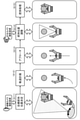
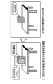
- FIG. 1 is a diagram illustrating a processing sequence when the robot 10 grips an object 50 which is an object to be gripped.
- the robot 10 operates in the order of steps S01 to S03 shown in the figure to grip the object 50.
- the robot 10 has a head 20, a hand 30, and an arm 40.
- the hand 30 is connected to the robot body by the arm 40, and has a configuration in which the position and orientation of the hand 30 can be changed by controlling the arm 40.
- the hand 30 has a rotatable movable portion corresponding to a human finger on both sides, and has a configuration capable of performing an object gripping operation and an object releasing operation.
- the robot 10 moves by driving a driving unit such as a leg or a wheel, and further moves the hand 30 to a position where the object 50 can be gripped by controlling the arm 40.
- a driving unit such as a leg or a wheel
- the robot body 10 may not move, and the hand 30 may be brought closer to the object by controlling only the arm 40.
- the processing of the present disclosure is applicable in any configuration. In the examples described below, as an example, a configuration example in which the robot 10 main body can also be moved will be described.
- the robot 10 has two cameras for confirming the position and the like of the object 50 which is the object to be grasped.
- One is a bird's-eye view camera 21 mounted on the head 20, and the other is a hand camera 31 mounted on the hand 30.
- the bird's-eye view camera 21 and the hand camera 31 include not only a camera for taking a visible light image but also a sensor capable of acquiring a distance image or the like. However, it is preferable to use a camera or a sensor that can obtain three-dimensional information. For example, a stereo camera, a sensor such as a ToF sensor or Lidar, or a combination of these sensors and a monocular camera may be used. It is preferable to use a camera or a sensor that can acquire data capable of analyzing the three-dimensional position of the object to be gripped.
- FIG. 1 shows a step of confirming the position of the object 50 by the bird's-eye view camera 21.
- the data processing unit in the robot 10 detects the object 50, which is the object to be gripped, from the image taken by the bird's-eye view camera 21, and calculates the three-dimensional position of the object 50. After confirming this position, the data processing unit of the robot 10 moves so as to approach the object 50.
- Step S02 shows a process in which the robot 10 approaching the object 50 moves the hand 30 to a position where the object 50 can be grasped. This control of the hand position is executed based on the analysis of the captured image of the hand camera 31 mounted on the hand 30.
- the data processing unit in the robot 10 detects the object 50, which is the object to be gripped, from the image taken by the hand camera 31, and calculates the three-dimensional position of the object 50. After confirming this position, the data processing unit of the robot 10 performs an adjustment process for setting the position and orientation of the hand 30 so that the object 50 can be gripped.
- Step S03 shows the gripping process after the adjustment process of the hand 30 in step S02.
- the movable parts on both sides of the hand 30 are operated to grip the object 50.
- FIG. 2 is a diagram showing a grasping sequence of the object 50 by the robot 10 described above with reference to FIG. 1 in more detailed processing units. The processes are executed in the order of steps S11 to S15 shown in FIG. Hereinafter, each processing step will be described in sequence.
- Step S11 First, in step S11, the target gripping position determination process is executed. First, the captured image of the bird's-eye view camera 21 attached to the head 20 of the robot 10 is analyzed, the object 50 which is the object to be gripped is detected, and the position of the object 50 is analyzed.
- Step S12 is an orbit planning step.
- the data processing unit of the robot 10 generates a movement path of the robot or a hand for approaching the calculated position of the object 50, that is, a trajectory plan, based on the position information of the object 50 which is the object to be gripped calculated in step S11. conduct.
- the position of the hand 30 after movement may be any position as long as the object to be gripped can be observed from the hand camera 31 attached to the hand 30.
- step S13 the robot or hand is moved according to the trajectory generated in step S12.
- the position of the hand 30 after movement is a position where the object to be gripped can be observed from the hand camera 31 attached to the hand 30.
- Step S14 Next, in step S14, the position and orientation of the hand 30 are finely adjusted. This control of the hand position is executed based on the analysis of the captured image of the hand camera 31 mounted on the hand 30.
- the data processing unit in the robot 10 detects the object 50, which is the object to be gripped, from the image taken by the hand camera 31, and calculates the position of the object 50. After confirming this position, the data processing unit of the robot 10 performs an adjustment process for setting the position and orientation of the hand 30 so that the object 50 can be gripped.
- Step S15 Finally, the movable parts on both sides of the hand 30 are operated to grip the object 50.
- the robot 10 first confirms the position of the object 50, which is the object to be gripped, based on the captured image of the bird's-eye view camera 21 mounted on the head 20. After that, after the hand 30 approaches the object 50, the captured image of the hand camera 31 attached to the hand 30 is analyzed, and the position and orientation of the hand 30 are finely adjusted to grip the object 50. ..
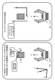
- FIG. 3 is a diagram illustrating a processing sequence when the robot 10 grips an object 50, which is an object to be gripped, as in FIG. 1 described above.
- the robot 10 operates in the order of steps S01 to S03 shown in the figure to grip the object 50.
- the difference from FIG. 1 is the shape of the object 50, which is the object to be gripped.
- the object 50 which is the object to be gripped has a spherical shape or a shape on a cylinder, but the object 50 which is the object to be gripped shown in FIG. 3 has a rectangular parallelepiped shape. ..
- FIG. 3 shows a step of confirming the position of the object 50 by the bird's-eye view camera 21.
- the data processing unit in the robot 10 detects the object 50, which is the object to be gripped, from the image taken by the bird's-eye view camera 21, and calculates the three-dimensional position of the object 50. After confirming this position, the data processing unit of the robot 10 moves so as to approach the object 50.
- Step S02 shows a process in which the robot 10 approaching the object 50 moves the hand 30 to a position where the object 50 can be grasped. This control of the hand position is executed based on the analysis of the captured image of the hand camera 31 mounted on the hand 30.
- the data processing unit in the robot 10 detects the object 50, which is the object to be gripped, from the image taken by the hand camera 31, and calculates the position of the object 50. After confirming this position, the data processing unit of the robot 10 performs an adjustment process for setting the position and orientation of the hand 30 so that the object 50 can be gripped.
- Step S03 shows the gripping process after the adjustment process of the hand 30 in step S02.
- the movable parts on both sides of the hand 30 are operated to try to grip the object 50.
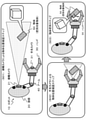
- the object 50 which is the object to be gripped, has a rectangular parallelepiped shape.
- the object 50 When gripping an object 50 having such a shape, the object 50 must be set to a specific direction in which stable gripping processing is possible with respect to the object 50, as shown in FIG. 3 (S03). It may rotate in the hand 30 and the gripping process may fail.
- the object 50 is a container containing water
- a situation may occur in which water spills from the container.
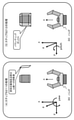
- FIG. 4 is a diagram showing an example of control processing of the robot 10 for stably holding an object 50 having such a rectangular parallelepiped shape.
- FIG. 4 shows an object gripping processing sequence by the robot 10 when the object 50, which is the object to be gripped, has a rectangular parallelepiped shape, as in FIG.
- the robot control device of the present disclosure has a configuration that enables processing as shown in FIG. 4, that is, control for stably gripping an object having various shapes.
- FIG. 4 the configuration and processing of the robot control device of the present disclosure will be described.
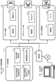
- FIG. 5 is a block diagram showing a configuration example of the robot control device 100 of the present disclosure.
- the robot control device 100 of the present disclosure shown in FIG. 5 is configured inside the robot 10 shown in FIGS. 1 to 4, for example.
- the robot control device 100 of the present disclosure includes a data processing unit 110, a robot head 120, a robot hand unit 130, a robot moving unit 140, a communication unit 150, and an input / output unit (user terminal) 180. ..
- the input / output unit (user terminal) 180 may be inside the robot body, or may be configured as a user terminal which is an independent device different from the robot body.
- the data processing unit 110 may also be installed in the robot body or in an independent device different from the robot body.
- the data processing unit 110 includes a gripping object point cloud extraction unit 111, a gripping object inclusion box generation unit 112, a gripping position calculation unit 113, and a control information generation unit 114.
- the robot head 120 has a drive unit 121 and a bird's-eye view camera 122.
- the robot hand unit 130 has a drive unit 131 and a hand camera 132.
- the robot moving unit 140 has a driving unit 141 and a sensor 142.
- components shown in FIG. 5 indicate the main components applied to the processing of the present disclosure, and there are various other components inside the robot, for example, components such as a storage unit.
- the drive unit 121 of the robot head 120 drives the robot head 120 and controls the orientation of the robot head 120. By this control, the image shooting direction of the bird's-eye view camera 122 is controlled.
- the bird's-eye view camera 122 captures an image observed from the robot head 120.
- the bird's-eye view camera 122 is not limited to a camera for taking a visible light image, and may be a sensor capable of acquiring a distance image or the like. However, it is preferable to use a camera or a sensor that can obtain three-dimensional information. For example, a stereo camera, a sensor such as a ToF sensor or Lidar, or a combination of these sensors and a monocular camera may be used. It is preferable to use a camera or a sensor that can acquire data capable of analyzing the three-dimensional position of the object to be gripped.
- the bird's-eye view camera 122 may be a monocular camera when it has a configuration for performing such an analysis process.
- the SLAM (simultaneous localization and mapping) process is a process of executing self-location identification (localization) and environment map creation (mapping) in parallel.
- the drive unit 131 of the robot hand unit 130 controls the orientation of the robot hand and controls the gripping operation.
- the hand camera 132 is a camera that captures an image immediately before the robot hand unit 130.
- This hand camera 132 is not limited to a camera for taking a visible light image, but may be a sensor capable of acquiring a distance image or the like. However, it is preferable to use a camera or a sensor that can obtain three-dimensional information. For example, a stereo camera, a sensor such as a ToF sensor or Lidar, or a combination of these sensors and a monocular camera may be used. It is preferable to use a camera or a sensor that can acquire data capable of analyzing the three-dimensional position of the object to be gripped.
- the robot control device 100 has a configuration for analyzing the three-dimensional position of an object in a captured image by, for example, SLAM processing
- the hand camera 132 is also a monocular camera. But it may be.
- the drive unit 141 of the robot moving unit 140 is, for example, a drive unit that drives the legs and wheels of the robot, and performs drive processing for moving the robot body.
- the sensor 142 is a sensor for detecting an obstacle in the moving direction of the robot, and is composed of a camera, a ToF sensor, Lidar, and the like.
- the data processing unit 110 includes a gripping object point cloud extraction unit 111, a gripping object inclusion box generation unit 112, a gripping position calculation unit 113, and a control information generation unit 114.
- the gripping object point cloud extraction unit 111 executes an extraction process of a point cloud (three-dimensional point cloud) indicating a gripping target object included in the captured image of the bird's-eye view camera 122 and the captured image of the hand camera 132.
- the point group corresponds to the outer shape of the object to be gripped, that is, the point group (three-dimensional point group) showing the three-dimensional shape of the object. A specific processing example will be described later.
- the gripping object inclusion box generation unit 112 generates a “grasping object inclusion box” including the three-dimensional point group based on the three-dimensional point group of the gripping object created by the gripping object point group extraction unit 111. do.
- the "grasping object inclusion box” is a box that includes a point cloud showing the three-dimensional shape of the gripping object, and the shape is not particularly limited, such as a rectangular parallelepiped, a cylinder, a cone, or a torus.
- a rectangular parallelepiped inclusion solid bounding box
- the gripping position calculation unit 113 executes the following processing, for example. (1) Relative relationship calculation processing between the gripping object inclusion box (bounding box) of the gripping object in the bird's-eye view camera image and the target gripping position, (2) The gripping object inclusion box of the gripping object in the hand camera image by applying the relative relationship between the gripping object inclusion box (bounding box) of the gripping object in the bird's-eye view camera image and the target gripping position. Calculation processing of the corrected target gripping position, which is the relative position of the target gripping position with respect to (bounding box), Perform these processes.
- the target gripping position is, for example, a target gripping position set by the user while viewing an image taken by a bird's-eye view camera using an input / output unit (user terminal) 180. It is a gripping position where the object to be gripped can be stably gripped by the hand of the robot, and corresponds to, for example, the contact position between the hand and the object to be gripped during the gripping process of the object to be gripped by the hand.
- the target gripping positions are set at two locations on both sides of the object 50. Specific examples and details will be described later.
- the gripping position calculation unit 113 (A) The gripping object inclusion box (bounding box) of the gripping object in the bird's-eye view camera image, (B) Grip target object inclusion box (bounding box) of the grip target object in the image taken by the hand camera. By generating two gripping object inclusion boxes (bounding boxes) of the gripping object in the images taken by these different cameras and matching the relative positions of each inclusion box (bounding box) with the gripping position, the user can use them. It is calculated which position of the gripping object included in the captured image of the hand camera corresponds to the set target gripping position. This calculated position is defined as the correction target gripping position.
- the control information generation unit 114 generates control information for gripping the "correction target grip position" calculated by the grip position calculation unit 113 by the hand of the robot. This control information is output to the drive unit 141 of the robot moving unit 140 and the drive unit 131 of the robot hand unit 130.
- the drive unit 141 of the robot moving unit 140 and the drive unit 131 of the robot hand unit 130 have the control information generated by the control information generation unit 114, that is, the “correction target gripping” calculated by the gripping position calculation unit 113 by the robot hand.
- the drive process is executed according to the control information for grasping the "position”. This drive process enables the robot hand to grip the "correction target gripping position".
- This "corrected target gripping position” is a gripping position that matches the target gripping position specified by the user while looking at the bird's-eye view image, and is a gripping position set on the gripping target object included in the captured image of the hand camera.
- the object By gripping the correction target gripping position set on the gripping object included in the image captured by the hand camera with the robot's hand, the object can be gripped stably. It is premised that the target gripping position specified by the user while looking at the bird's-eye view image does not include [0] recognition error or machine error.
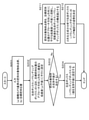
- FIG. 6 is a flowchart illustrating a calculation processing sequence of the gripping position (correction target gripping position) of the gripping target object executed by the data processing unit 110 of the robot control device 100 shown in FIG.
- the "correction target gripping position” is a gripping position capable of stably gripping the object to be gripped included in the captured image of the hand camera, and is designated by the user while looking at the bird's-eye view image. It is a gripping position that matches the target gripping position.
- the processing according to the flow shown in FIG. 6 is a control unit (data processing) composed of a CPU or the like having a program execution function of the information processing device according to the program stored in the storage unit (memory) of the robot control device 100. It is a process that can be executed under the control of the part).
- data processing composed of a CPU or the like having a program execution function of the information processing device according to the program stored in the storage unit (memory) of the robot control device 100. It is a process that can be executed under the control of the part).
- steps S111 to S114 are processes executed based on the captured image (including the distance image) of the bird's-eye view camera 122 of the robot head 120.
- steps S121 to S123 are processes executed based on the captured image (including the distance image) of the hand camera 132 of the robot hand unit 130.
- Step S111 First, the data processing unit 110 of the robot control device 100 inputs the designation information of the gripping target object using the bird's-eye view camera captured image and the designation information of the target gripping position.
- the designated information of the object to be gripped and the designated information of the target gripping position are input by the user while viewing the captured image of the bird's-eye view camera using, for example, the input / output unit (user terminal) 180.
- the input / output unit (user terminal) 180 A specific example of this process will be described with reference to FIG. 7.
- FIG. 7 shows the following figures. (1) Example of designation processing of the object to be gripped (2) Example of designation of the gripping position of the object to be gripped
- FIGS. 7 (1) and 7 (2) are images taken by the bird's-eye view camera 122 displayed on the display unit of the input / output unit (user terminal) 180. That is, the image taken by the bird's-eye view camera 122 is an image in which a rectangular parallelepiped object to be gripped is placed on a table. In this way, the user inputs the designation information of the object to be gripped and the designation information of the target gripping position while looking at the captured image of the bird's-eye view camera displayed on the input / output unit (user terminal) 180.
- FIG. 7 (1) is an input example of designated information of the object to be gripped.
- the user designates the gripping object by a method such as setting a rectangular area surrounding the rectangular parallelepiped gripping object.
- the user specifies a gripping position (target gripping position) for stably gripping the object to be gripped.
- a gripping position target gripping position
- a method of designating the gripping position as shown in the figure, there are a method of directly designating the gripping position on the surface of the object to be gripped and a method of setting an arrow indicating the gripping position.
- the gripping position of the surface of the object to be gripped having a rectangular parallelepiped shape is set to be substantially the center position of the two facing surfaces on both sides.
- one surface is in a position observable from the image taken by the bird's-eye view camera, and this point can directly specify the gripping position on the surface of the object to be gripped. ..
- one side is in a position that cannot be seen in the image taken by the bird's-eye view camera.
- the user sets an arrow indicating the gripping position as shown in the figure.
- a three-dimensional image of the object to be gripped is displayed on the display unit, and a marker on which the user can interactively set the position information is displayed on the display data, and the user moves the marker to directly set the gripping position.
- the method of specifying the target may be applied.
- the data processing unit 110 of the robot control device 100 determines this designated position as the target gripping position, and this position information (position relative to the object to be gripped, Alternatively, the three-dimensional position of the target gripping position) is stored in the storage unit. Further, when the user does not directly specify the gripping position on the surface of the object to be gripped and sets an arrow, the data processing unit 110 of the robot control device 100 determines the intersection of the arrow set by the user and the object to be gripped. Is calculated and this intersection is determined as the target gripping position, and this position information (relative position with respect to the gripping object or the three-dimensional position of the target gripping position) is stored in the storage unit.
- the gripping position is a point where the robot's hand can stably grip and lift the object to be gripped, and the number of gripping positions varies depending on the configuration of the robot's hand.
- the robot hand has a gripper type having two movable parts that can rotate left and right respectively.
- this gripper type hand configuration since the two movable parts grip the object to be gripped from the left and right, each of the two movable parts on the left and right sets two points in contact with the object to be gripped as gripping positions. do it.
- processing is performed such that three points where each finger contacts the object to be gripped are designated as gripping positions.
- the designated information of the object to be gripped and the designation of the target gripping position are specified.
- the data processing unit 110 of the robot control device 100 determines the gripping object and the target gripping position on the gripping object based on the input information.
- Step S112 Next, the process of step S112 of the flow of FIG. 6 will be described.
- step S112 a point cloud extraction process of the object to be gripped in the image taken by the bird's-eye view camera is executed.
- This process is a process executed by the gripping object point cloud extraction unit 111 of the data processing unit 110 of the robot control device 100.
- the gripping object point cloud extraction unit 111 executes a point cloud (three-dimensional point cloud) extraction process indicating the gripping target object based on the gripping target object selected from the captured image of the bird's-eye view camera 122.
- the point group corresponds to the outer shape of the object to be gripped, that is, the point group (three-dimensional point group) showing the three-dimensional shape of the object.
- FIG. 8 shows each of the following figures. (1) Grasping target object and gripping target object designation information, (2) Example of a point cloud (three-dimensional point cloud) of an object to be grasped
- FIG. 8 (1) shows a gripping target object selected from the captured image of the bird's-eye view camera 122 and a rectangular area as designated information of the gripping target object designated by the user.
- the gripping target object point cloud extraction unit 111 sets an object in a designated rectangular region as a gripping target object, and extracts a point cloud corresponding to the object.
- the gripping object point cloud extraction unit 111 needs to perform a process of removing a point cloud other than the point cloud related to the gripping target object included in the rectangular region designated by the user.
- the point group corresponding to the support plane (table) is removed.
- a clustering process for classifying the point cloud for each individual object is effective. Is.
- the point cloud is divided into clusters for each object, and then the point cloud consisting of the clusters containing the largest number of clusters in the rectangular area, which is the designated area of the object to be gripped set by the user, is used as the point cloud corresponding to the object to be gripped. Extract.
- Other point cloud clusters are point clouds of objects other than the object to be gripped, so they are deleted. By performing such a process, for example, a point cloud (three-dimensional point cloud) of the object to be gripped as shown in FIG. 8 (2) can be extracted.
- an existing method such as the RANSAC method can be applied to the detection process of the support plane such as the table on which the object to be gripped is placed. Further, for clustering, existing methods such as Euclidean Clustering can be applied.
- Step S113 Next, the process of step S113 of the flow of FIG. 6 will be described.
- step S113 a process of generating an inclusion box (bounding box) of the object to be gripped in the image captured by the bird's-eye view camera is performed.
- This process is a process executed by the gripping object inclusion box generation unit 112 of the data processing unit 110 of the robot control device 100.
- the gripping object inclusion box generation unit 112 generates a “grasping object inclusion box” including the three-dimensional point group based on the three-dimensional point group of the gripping object created by the gripping object point group extraction unit 111. do.
- the shape of the "grasping object inclusion box” is not particularly limited, such as a rectangular parallelepiped, a cylinder, a cone, and a torus, and can be various shapes. However, in this embodiment, an example in which a bounding box having a rectangular parallelepiped shape is used as the “object inclusion box to be gripped” will be described.
- step S113 describes the detailed sequence of the process of step S113, that is, the process of generating the inclusion box (bounding box) of the object to be gripped in the bird's-eye view camera captured image executed by the grasped object inclusion box generation unit 112. Will be described with reference to.
- Step S201 First, the gripping object inclusion box generation unit 112 inputs the following information in step S201.
- A Point cloud of objects to be gripped based on the bird's-eye view camera
- b Target gripping position
- the gripping target object point cloud based on the bird's-eye view camera is the point cloud data generated by the gripping target object point cloud extraction unit 111, and is input from the gripping target object point cloud extraction unit 111.
- the target gripping position is the target gripping position input by the user, and is the target gripping position input by the user in step S111 of the flow of FIG.
- step S302 the gripping object inclusion box generation unit 112 makes one side of the inclusion box (bounding box) parallel to the vertical plane (yz plane) perpendicular to the approach direction (x direction) of the target gripping position. Perform the setting process.
- FIG. 10 (1) shows an example of a coordinate system and input information in the inclusion box (bounding box) generation process.
- the approach direction in which the hand 30 approaches the object 50 is set to the x direction, and the movable part of the hand 30 is set to the target gripping position when the hand 30 is gripped.
- the y-axis is the moving direction for approaching. Further, it is a right-handed coordinate system in which the direction perpendicular to the x-axis and the y-axis is set as the z-axis.
- step S202 one side of the inclusion box (bounding box) is set parallel to the vertical plane (yz plane) perpendicular to the approach direction (x direction) of the target gripping position.
- FIG. 10 (2) A specific example is shown in FIG. 10 (2). As shown in FIG. 10 (2), a side parallel to the vertical plane (yz plane) perpendicular to the approach direction (x direction) of the target gripping position is set as one side of the inclusion box (bounding box).
- FIG. 11 (2a) is an example of generating an unfavorable bounding box
- FIG. 11 (2b) is an example of generating a preferable bounding box.
- the gripping object inclusion box generation unit 112 further sets one surface of the bounding box to face the approach direction (x direction) of the hand 30, as shown in FIG. 11 (2b). do. That is, the rotation (yaw angle) around the z-axis is adjusted for the bounding box having sides parallel to the yz plane so that one side of the bounding box faces the approach direction (x direction) of the hand 30. Set.
- Step S203 the gripping object inclusion box generation unit 112 determines whether or not the support plane of the gripping target object exists.
- the support plane is, for example, a plane such as a table on which an object to be gripped is placed.
- step S204 If there is a support plane for the object to be gripped, the process proceeds to step S204. On the other hand, if the support plane of the object to be gripped does not exist, the process proceeds to step S211.
- Step S204 If it is determined in step S203 that the support plane of the object to be gripped exists, the process proceeds to step S204.
- the gripping object inclusion box generation unit 112 sets one surface of the inclusion box (bounding box) on the support plane to generate the inclusion box (bounding box).
- step S204 will be described with reference to FIG.
- the example shown in FIG. 12 (3a) shows a state in which the object to be gripped is placed on a table which is a support plane.
- step S204 the gripping object inclusion box generation unit 112 sets one surface of the inclusion box (bounding box) on the support plane (table) as shown in FIG. 12 (3a).
- FIGS. 10 (2) and 11 (2b) (2) By connecting the sides set parallel to the vertical plane (yz plane) perpendicular to the x direction, an inclusion box (bounding box) is generated. As a result, for example, an inclusion box (bounding box) as shown in FIG. 13 (3b) is generated.
- Step S211 On the other hand, if it is determined in step S203 that the support plane of the object to be gripped does not exist, the process proceeds to step S211.
- the gripping object inclusion box generation unit 112 projects the gripping object point group on a vertical plane (zx plane) parallel to the approach direction (y direction) of the target gripping position, and includes the projection plane. It is a constituent surface of (bounding box).
- the gripping object inclusion box generation unit 112 projects the gripping object point group onto a vertical plane (zx plane) parallel to the approach direction (y direction) of the target gripping position.
- This projection plane is used as a constituent plane of the inclusion box (bounding box).
- the projection plane generated by this projection process is the “projection plane of the object point cloud to be gripped on the xz plane” shown in FIG. 14 (4).
- step S212 the gripping object inclusion box generation unit 112 executes a two-dimensional principal component analysis on the projected point cloud to determine the posture of the inclusion box (bounding box) around the pitch axis (y-axis). do.
- the gripping object point group projected onto the xz plane is a point group that originally spreads in the three-dimensional space of the gripping object having a three-dimensional shape and is projected onto the two-dimensional plane (xz plane).
- a two-dimensional principal component analysis can be performed on a group of points developed on this two-dimensional plane to determine an inclusion box (bounding box) having a shape that includes a gripping object having a three-dimensional shape. .. Specifically, the posture around the pitch axis (y-axis) of the inclusion box (bounding box) is determined by the two-dimensional principal component analysis for the projection point group.
- an inclusion box as shown in FIG. 14 (5) can be generated.
- the three-axis principal component analysis may be directly applied.
- the inclusion box (bounding box) is generated so that the three-dimensional position of the target gripping position is included in the inclusion box (bounding box). A more accurate inclusion box (bounding box) generation process is realized.
- step S113 of the flow shown in FIG. 6, that is, the process of generating the inclusion box (bounding box) of the grip target object in the bird's-eye view camera captured image by the grip target object inclusion box generation unit 112 have been described. ..
- the gripping object inclusion box generation unit 112 includes the three-dimensional point group of the gripping object based on the three-dimensional point group of the gripping object generated by the gripping object point group extraction unit 111. Generate a "grabbing object inclusion box (bounding box)".
- step S114 a process of calculating the relative positional relationship between the inclusion box (bounding box) of the object to be gripped in the image captured by the bird's-eye view camera and the target gripping position is executed.
- This process is a process executed by the gripping position calculation unit 113 of the data processing unit 110 of the robot control device 100.
- the gripping position calculation unit 113 executes a calculation process of the relative positional relationship between the gripping target object inclusion box (bounding box) of the gripping target object in the bird's-eye view camera image and the target gripping position.
- the target gripping position is a gripping position set by the user while viewing the image taken by the bird's-eye view camera using, for example, the input / output unit (user terminal) 180, and the object to be gripped is held by the robot's hand. It is a gripping position determined by the user to be able to grip stably.
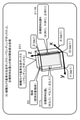
- FIG. 15 shows a bird's-eye view camera reference inclusion box (bounding box) 201 including an object 50 which is an object to be grasped and an object 50 generated by the object inclusion box generation unit 112 to be grasped in step S113 of the flow shown in FIG. Is shown.
- bounding box bounding box
- the bird's-eye view camera reference inclusion box (bounding box) 201 is an inclusion box (bounding box) generated based on the captured image of the bird's-eye view camera 122.
- the gripping position calculation unit 113 generates a coordinate system (overhead camera reference inclusion box coordinate system) with one vertex of the bird's-eye view camera reference inclusion box (bounding box) 201 as the origin.
- the bird's-eye camera reference inclusion box coordinate system has a rectangular parallelepiped shape with one vertex of the inclusion box (bounding box) 201 as the origin (O (bb1)). This is a coordinate system in which each side of 201 is set on the X, Y, and Z axes.
- the bird's-eye view camera reference inclusion box (bounding box) 201 includes an origin (O (bb1)) on the bird's-eye view camera reference inclusion box coordinate system, a point on the X-axis (X (bb1)), and a point on the Y-axis (Y). (Bb1)), a point on the Z axis (Z (bb1)), and a rectangular parallelepiped having these four points as vertices.
- FIG. 15 further shows the three-dimensional position coordinates of the target gripping position in the bird's-eye view camera reference inclusion box coordinate system. The following two points are shown in FIG. Target gripping position L ((X (L1), Y (L1), Z (L1)), 211L Target gripping position R ((X (R1), Y (R1), Z (R1)), 211R These two points.
- the target gripping position is the target gripping position set by the user while viewing the captured image of the bird's-eye view camera using, for example, the input / output unit (user terminal) 180.
- the gripping position calculation unit 113 calculates the target gripping position set by the user as a three-dimensional position on the coordinate system (overhead camera reference inclusion box coordinate system) shown in FIG. That is, it is the three-dimensional position coordinates of the following two points shown in FIG.
- Target gripping position L ((X (L1), Y (L1), Z (L1)), 211L
- Target gripping position R ((X (R1), Y (R1), Z (R1)), 211R
- the coordinates of this target gripping position are coordinates in which one vertex of the inclusion box (bounding box) is set as the origin and each side of the bird's-eye view camera reference inclusion box (bounding box) 201 having a rectangular parallelepiped shape is set on the X, Y, and Z axes. Coordinates in the system. Therefore, the coordinates of the target gripping position shown in FIG. 15 are the coordinates indicating the relative positional relationship between the inclusion box (bounding box) of the gripping object in the bird's-eye view camera image and the target gripping position.
- the gripping position calculation unit 113 calculates the relative positional relationship between the gripping target object inclusion box (bounding box) of the gripping target object in the bird's-eye view camera captured image and the target gripping position.
- steps S121 to S123 shown in FIG. 6 are processes executed based on the captured image of the hand camera 132 of the robot hand unit 130.
- step S121 the point cloud extraction process of the object to be grasped in the image captured by the hand camera is executed.
- This process is a process executed by the gripping object point cloud extraction unit 111 of the data processing unit 110 of the robot control device 100.
- the gripping object point cloud extraction unit 111 extracts a point cloud (three-dimensional point cloud) indicating the gripping target object included in the captured image of the hand camera 132.
- the point cloud corresponds to the outer shape of the object to be gripped, that is, the point cloud (three-dimensional point cloud) showing the three-dimensional shape of the object.
- a point cloud (three-dimensional point cloud) of the object to be gripped as shown in FIG. 8 (2) is generated.
- the point cloud extraction using the rectangular area designated by the user-designated object to be gripped was performed.
- the captured image of the hand camera 132 is displayed on the input / output unit (user terminal) 180, and the user is allowed to specify the grip target object to set a rectangular area.
- the same processing may be performed, but it is also possible to perform the same processing without specifying the rectangular area by the user. That is, the process of extracting the object to be gripped from the image captured by the hand camera 132 is autonomously executed with reference to the shape and size of the inclusion box (bounding box) generated based on the image captured by the bird's-eye view camera 122. Is possible.
- the Min-Cut Based Segmentation process known as a method for extracting a specific object from an image is applied to execute a gripping object extraction process. That is, by applying a method such as setting the seed point and size to the point cloud and size included in the inclusion box (bounding box) of the bird's-eye view camera standard by the Min-Cut Based Segmentation process and extracting the foreground.
- the process of extracting the object to be gripped from the captured image of the hand camera 132 is executed.
- processing such as detection processing of a support plane such as a table on which the object to be gripped is placed and processing such as clustering may be added.
- an existing method such as a RANSAC method can be applied to the detection process of a support plane such as a table on which an object to be gripped is placed.
- existing methods such as Euclidean Clustering can be applied.
- the parameters are changed again and the extraction is performed. It is preferable to execute a process such as changing the point cloud to be used.
- a process such as changing the point cloud to be used.
- the point cloud (three-dimensional point cloud) of the gripping object as shown in FIG. 8 (2) is represented by the point cloud (three-dimensional point cloud) indicating the gripping object included in the captured image of the hand camera 132. It can be extracted as a three-dimensional point cloud).
- step S122 Next, the process of step S122 of the flow of FIG. 6 will be described.
- step S122 a process of generating an inclusion box (bounding box) of the object to be gripped in the image captured by the hand camera is performed.
- This process is a process executed by the gripping object inclusion box generation unit 112 of the data processing unit 110 of the robot control device 100.
- the gripping object inclusion box generation unit 112 includes the three-dimensional point group based on the three-dimensional point group of the gripping object in the captured image of the hand camera 132 generated by the gripping object point group extraction unit 111. Generate a "grasping object inclusion box".
- the inclusion box generated by the gripping object inclusion box generation unit 112, that is, the inclusion box containing the gripping object of the hand camera captured image, is an inclusion box having the same shape as the inclusion box previously generated in step S113.
- the "grasping object inclusion box” is not particularly limited in shape such as a rectangular parallelepiped, a cylinder, a cone, and a torus, and can have various shapes.
- the "object inclusion box” is a bounding box having a rectangular parallelepiped shape, and also in this step S122, a bounding box having a rectangular parallelepiped shape is generated.
- step S122 that is, the process of generating the inclusion box (bounding box) of the object to be gripped in the hand-held camera captured image executed by the gripping object inclusion box generation unit 112. I will explain.
- Step S301 First, the gripping object inclusion box generation unit 112 inputs the following information in step S301.
- A Point cloud to be grasped based on the hand camera
- Inclusion box (bounding box) based on the bird's-eye view camera
- C Target gripping position
- the grip target object point cloud based on the hand camera is point cloud data generated by the grip target object point cloud extraction unit 111 based on the captured image of the hand camera in step S121, and is the point cloud data generated by the grip target object point cloud extraction unit 111.
- Enter from. (B) The inclusion box (bounding box) based on the bird's-eye view camera is the inclusion box (bounding box) generated in step S113 of the flow of FIG. 6, and is input from the gripping object point inclusion box generation unit 112.
- the target gripping position is the target gripping position input by the user in step S111 of the flow of FIG.
- step S302 the gripping object inclusion box generation unit 112 makes one side of the inclusion box (bounding box) parallel to the vertical plane (yz plane) perpendicular to the approach direction (x direction) of the target gripping position. Perform the setting process.
- step S302 one side of the inclusion box (bounding box) is set parallel to the vertical plane (yz plane) perpendicular to the approach direction (x direction) of the target gripping position.
- a side parallel to the vertical plane (yz plane) perpendicular to the approach direction (x direction) of the target gripping position is set as one side of the inclusion box (bounding box). do.
- FIG. 11 (2a) is an example of generating an unfavorable bounding box
- FIG. 11 (2b) is an example of generating a preferable bounding box.
- the gripping object inclusion box generation unit 112 further sets one surface of the bounding box to face the approach direction (x direction) of the hand 30, as shown in FIG. 11 (2b). do. That is, the rotation (yaw angle) around the z-axis is adjusted for the bounding box having sides parallel to the yz plane so that one side of the bounding box faces the approach direction (x direction) of the hand 30. Set.
- Step S303 the gripping object inclusion box generation unit 112 determines whether or not the support plane of the gripping target object exists.
- the support plane is, for example, a plane such as a table on which an object to be gripped is placed.
- step S304 If there is a support plane for the object to be gripped, the process proceeds to step S304. On the other hand, if the support plane of the object to be gripped does not exist, the process proceeds to step S311.
- Step S304 If it is determined in step S303 that the support plane of the object to be gripped exists, the process proceeds to step S304.
- step S304 the gripping object inclusion box generation unit 112 sets one surface of the inclusion box (bounding box) on the support plane to generate the inclusion box (bounding box).
- step S304 is the same as the process of step S204 of the flow of FIG. 9 described above. That is, it is the process described above with reference to FIGS. 12 and 13.
- the example shown in FIG. 12 (3a) shows a state in which the object to be gripped is placed on a table which is a support plane.
- step S304 the gripping object inclusion box generation unit 112 sets one surface of the inclusion box (bounding box) on the support plane (table) as shown in FIG. 12 (3a).
- step S302 the approach direction of the target gripping position described above with reference to the surface set on the support plane (table) and the side previously generated in step S302, that is, FIGS. 10 (2) and 11 (2b) (2).
- an inclusion box is generated.
- an inclusion box as shown in FIG. 13 (3b) is generated.
- Step S311 On the other hand, if it is determined in step S303 that the support plane of the object to be gripped does not exist, the process proceeds to step S311.
- the gripping object inclusion box generation unit 112 uses the inclusion box (bounding box) having the same posture as the inclusion box (bounding box) based on the image captured by the bird's-eye view camera 122 that has already been generated into the image captured by the hand camera 132. Set as a based inclusion box (bounding box).
- the inclusion box (bounding box) having the same posture as the inclusion box (bounding box) based on the image taken by the bird's-eye view camera 122 generated in step S113 of the flow shown in FIG. 6 is the inclusion box (bounding) based on the image taken by the hand camera 132. Box).
- step S123 the inclusion box (bounding box) of the object to be gripped in the image captured by the hand camera is applied by applying the relative positional relationship between the inclusion box (bounding box) of the object to be gripped in the bird's-eye view camera image and the target grip position.
- the calculation process of the corrected target gripping position which is the relative position of the target gripping position with respect to the target, is executed.
- the relative position of the target gripping position of the gripping object with respect to the inclusion box (bounding box) of the gripping object in the bird's-eye view camera image is calculated, and the hand camera in the hand camera's shot image is based on the calculated relative position.
- the target gripping position with respect to the reference inclusion box is calculated, and the calculated position is set as the correction target gripping position of the gripping object included in the captured image of the hand camera.
- This process is a process executed by the gripping position calculation unit 113 of the data processing unit 110 of the robot control device 100 shown in FIG.
- the gripping position calculation unit 113 applies the relative positional relationship between the inclusion box (bounding box) of the object to be gripped in the bird's-eye view camera image and the target grip position, and the inclusion box (bounding box) of the object to be gripped in the hand camera image.
- the calculation process of the corrected target gripping position which is the relative position of the target gripping position with respect to the bounding box), is executed.
- the target gripping position is a gripping position set by the user while viewing the image taken by the bird's-eye view camera using, for example, the input / output unit (user terminal) 180, and the object to be gripped is held by the robot's hand. It is a gripping position determined by the user to be able to grip stably.
- step 114 of the flow shown in FIG. 6, which is a process based on the image taken by the bird's-eye view camera 122 described above with reference to FIG. 15, the inclusion box (bounding box) and the target of the object to be gripped in the image taken by the bird's-eye view camera.
- the relative position to the gripping position is calculated.
- step S123 the target gripping position in the bird's-eye view camera image is set to the hand camera image by using the relative positional relationship between the inclusion box (bounding box) of the object to be gripped in the bird's-eye view camera image and the target gripping position. Calculate the position with respect to the inclusion box (bounding box) of the object to be gripped inside.
- the calculation process of the correction target gripping position which is the relative position of the target gripping position with respect to the inclusion box (bounding box) of the object to be gripped in the image captured by the hand camera, is executed.
- the gripping position calculation unit 113 in step S123 (A) A gripping object inclusion box (bounding box) of the gripping object in the captured image of the bird's-eye view camera 122, (B) Grip target object inclusion box (bounding box) of the grip target object in the captured image of the hand camera 132.
- a gripping object inclusion box (bounding box) of the gripping object in the captured image of the bird's-eye view camera 122 (B) Grip target object inclusion box (bounding box) of the grip target object in the captured image of the hand camera 132.
- the correction target gripping position in the captured image of the hand camera 132 set by this process is a position corresponding to the target gripping position set by the user while looking at the captured image of the bird's-eye view camera 122. Therefore, the robot control device 100 observes the captured image of the hand camera 132 and hands at the corrected target gripping position which is a relative position of the target gripping position with respect to the inclusion box (bounding box) of the gripping object in the hand camera captured image. By abutting the gripper of the object 50 and performing the gripping process of the object 50, the object 50 can be stably gripped.
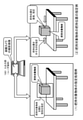
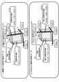
- step S123 will be described with reference to FIG. FIG. 17 shows the following two figures. (1) Analysis data based on the bird's-eye view camera (2) Analysis data based on the hand camera
- the analysis data based on the bird's-eye view camera is data generated based on the captured image of the bird's-eye view camera 122. That is, it is the data generated by the processing of steps S111 to S114 of the flow shown in FIG. 6, and corresponds to the data described above with reference to FIG.
- the analysis data based on the hand camera is data generated based on the captured image of the hand camera 132. That is, it is the data generated by the processing of steps S121 to S123 of the flow shown in FIG.
- step S113 of the flow shown in FIG. 6 the bird's-eye view camera reference inclusion box (bounding box) 201, which includes the object 50 generated by the gripping object inclusion box generation unit 112, (1c) In step S111 of the flow shown in FIG. 6, the target gripping positions 211L and 211R set by the user based on the captured image of the bird's-eye view camera 122. Each of these data is shown.
- the bird's-eye view camera reference inclusion box (bounding box) 201 having a rectangular parallelepiped shape has one vertex of the inclusion box (bounding box) 201 as the origin (O (bb1)). This is a coordinate system in which each side is set on the X, Y, and Z axes.
- the bird's-eye view camera reference inclusion box (bounding box) 201 includes the origin (O (bb1)) of the bird's-eye view camera reference inclusion box coordinate system, a point on the X-axis (X (bb1)), and a point on the Y-axis (Y (Y ()). It is defined as a rectangular parallelepiped having bb1)), a point on the Z axis (Z (bb1)), and these four points as vertices.
- FIG. 17 (1) further shows the three-dimensional position coordinates of the target gripping position in the bird's-eye view camera reference inclusion box coordinate system. The following two points are shown in FIG. 17 (1).
- Target gripping position L ((X (L1), Y (L1), Z (L1)), 211L
- Target gripping position R ((X (R1), Y (R1), Z (R1)), 211R
- these two points are gripping positions set by the user while viewing the captured image of the bird's-eye view camera using, for example, the input / output unit (user terminal) 180.
- the coordinates of the target gripping position shown in FIG. 17 (1) are the inclusion box (bounding box) of the gripping object and the target gripping position in the image taken by the bird's-eye view camera. These are the coordinates indicating the relative positional relationship of.
- step S123 of the flow of FIG. 6 the gripping position calculation unit 113 executes the following processing. That is, the target for the inclusion box (bounding box) of the gripping object in the hand camera image by applying the relative positional relationship between the inclusion box (bounding box) of the gripping object in the bird's-eye view camera image and the target gripping position.
- the calculation process of the correction target gripping position which is the relative position of the gripping position, is executed.
- the relative position of the target gripping position of the gripping target object with respect to the inclusion box (bounding box) of the gripping target object in the bird's-eye view camera image is calculated, and based on the calculated relative position, the hand camera captured image.
- the target gripping position with respect to the hand camera reference inclusion box is calculated, and the calculated position is set as the correction target gripping position of the gripping object included in the captured image of the hand camera.
- the correction target gripping position is the correction target gripping position shown in FIG. 17 (2). That is, the correction target gripping position shown in FIG. 17 (2).
- Correction target gripping position L ((X (L2), Y (L2), Z (L2)), 231L
- Correction target gripping position R ((X (R2), Y (R2), Z (R2)), 231R
- the hand camera reference inclusion box coordinate system has one vertex of the hand camera reference inclusion box (bounding box) 221 as the origin (O (bb2)), and each side of the hand camera reference inclusion box (bounding box) 221 having a rectangular parallelepiped shape. Is a coordinate system in which is set on the X, Y, and Z axes.
- the hand camera reference inclusion box (bounding box) 221 has an origin (O (bb1)) on the hand camera reference inclusion box coordinate system, a point on the X axis (X (bb1)), and a point on the Y axis (Y). (Bb1)), a point on the Z axis (Z (bb1)), and a rectangular parallelepiped having these four points as vertices.
- step S123 of the flow of FIG. 6 the gripping position calculation unit 113 applies the relative positional relationship between the inclusion box (bounding box) of the object to be gripped in the bird's-eye view camera captured image and the target gripping position, and the hand camera captured image.
- the calculation process of the correction target gripping position which is the relative position of the target gripping position with respect to the inclusion box (bounding box) of the object to be gripped in the inside, is executed.
- correction target gripping position L ((X (L2), Y (L2), Z (L2)), 231L shown in FIG. 17 (2)).
- Correction target gripping position R ((X (R2), Y (R2), Z (R2)), 231R
- the correction target gripping position calculation process executed by the gripping position calculation unit 113 is executed as follows. First, the target gripping position in the bird's-eye camera reference inclusion box coordinate system included in the analysis data of the bird's-eye camera reference shown in FIG. 17 (1), that is, Target gripping position L ((X (L1), Y (L1), Z (L1)), 211L Target gripping position R ((X (R1), Y (R1), Z (R1)), 211R A relational expression is generated in which the coordinates of these two points are shown using the vertex data (X (bb1), Y (bb1), Z (bb1)) of the bird's-eye view camera reference inclusion box (bounding box) 201.
- Two such relational expressions (relational expression 1) and (relational expression 2) are generated.
- lx, ly, lz shown in (relational expression 1) are the coordinates ((X (L1)), Y (L1) of the target gripping position L with respect to the length of each side of the bird's-eye view camera reference inclusion box (bounding box) 201. ), Z (L1)) xyz is a coefficient indicating the ratio of each coordinate position.
- rx, ry, and rz shown in (relational expression 2) are the coordinates of the target gripping position R with respect to the length of each side of the bird's-eye view camera reference inclusion box (bounding box) 201 ((X (R1), Y (). It is a coefficient indicating the ratio of each xyz coordinate position of R1) and Z (R1)).
- the coefficients lx, ly, liz and the coefficients rx, ry, rg are calculated based on these two relational expressions (relational expression 1) and (relational expression 2).
- correction target gripping positions L and R are calculated using the following calculation formulas (calculation formula 1) and (calculation formula 2).
- the correction target gripping positions L and R are calculated by these two calculation formulas (calculation formula 1) and (calculation formula 2).
- the gripping position calculation unit 113 performs the correction target gripping position which is a relative position of the target gripping position with respect to the inclusion box (bounding box) of the gripping target object in the image captured by the hand camera in step S123 of the flow of FIG. Executes the calculation process of.
- the correction target gripping position in the captured image of the hand camera 132 set by this process is a position corresponding to the target gripping position set by the user while looking at the captured image of the bird's-eye view camera 122. Therefore, the robot control device 100 observes the captured image of the hand camera 132 and hands at the corrected target gripping position which is a relative position of the target gripping position with respect to the inclusion box (bounding box) of the gripping object in the hand camera captured image. By abutting the gripper of the object 50 and performing the gripping process of the object 50, the object 50 can be stably gripped.
- the robot control device 100 of the present disclosure is (A) The gripping object inclusion box (bounding box) of the gripping object in the bird's-eye view camera image, (B) Grip target object inclusion box (bounding box) of the grip target object in the image taken by the hand camera.
- A The gripping object inclusion box (bounding box) of the gripping object in the bird's-eye view camera image
- B Grip target object inclusion box (bounding box) of the grip target object in the image taken by the hand camera.
- the control information generation unit 114 generates control information for gripping the "correction target grip position" calculated by the grip position calculation unit 113 by the hand of the robot. This control information is output to the drive unit 141 of the robot moving unit 140 and the drive unit 131 of the robot hand unit 130.
- the drive unit 141 of the robot moving unit 140 and the drive unit 131 of the robot hand unit 130 have the control information generated by the control information generation unit 114, that is, the “correction target gripping” calculated by the gripping position calculation unit 113 by the robot hand.
- the drive process is executed according to the control information for grasping the "position”.
- This drive process enables the robot hand to grip the "correction target gripping position".
- This "corrected target gripping position” is a gripping position that matches the target gripping position specified by the user while looking at the bird's-eye view image, and is a gripping position set on the gripping target object included in the captured image of the hand camera.
- steps S111 to S114 is a captured image (also a distance image) of the bird's-eye view camera 122 of the robot head 120. It is a process executed based on (including).
- steps S121 to S123 are processes executed based on the captured image (including the distance image) of the hand camera 132 of the robot hand unit 130.
- steps S111 to S114 executed based on the captured image (including the distance image) of the bird's-eye view camera 122 and the step S121 executed based on the captured image (including the distance image) of the hand camera 132 are executed.
- the processing of step S122 can be executed in parallel. Further, after the processing of steps S111 to S114 is completed, the processing of steps S121 to S122 may be executed.
- step S123 is executed based on the processing of steps S111 to S114 executed based on the captured image (including the distance image) of the bird's-eye view camera 122 and the captured image (including the distance image) of the hand camera 132. This is executed after the processing of steps S121 to S122 is completed.
- the processing procedure it is preferable to set the processing procedure so that the object 50, which is the object to be gripped, can be reliably observed in the captured images of the bird's-eye view camera 122 and the hand camera 132.
- a portion such as an arm or a hand obstructs the field of view of the bird's-eye view camera 122, and it is possible to avoid processing in a state where occlusion occurs in the object to be gripped.
- step S111 of the flow shown in FIG. 6 the processing of inputting the designation information of the object to be gripped using the image taken by the bird's-eye view camera and the designation information of the target gripping position is performed. I was going.
- the user can specify the designated object to be gripped and the target gripping position while viewing the captured image of the bird's-eye view camera using the input / output unit (user terminal) 180. I was entering information.
- the user may perform a process of selecting a rectangle corresponding to the object. Further, a method of extracting an object in pixel units by semantic segmentation and selecting the object by the user may be applied. Further, when the target gripping position has already been determined, the process of automatically selecting the object closest to the target gripping position may be performed. Further, as for the method of determining the target gripping position, the user may not directly determine the position and posture, but may specify only the object to be gripped, perform a gripping plan, and autonomously determine the target gripping position.
- step S112 of the flow shown in FIG. 6 a process of executing a point cloud extraction process of the object to be gripped in the image taken by the bird's-eye view camera was performed.
- this process is executed as a process of extracting a group of object points corresponding to a rectangular area specified by the user. Similar to the process of designating the object to be gripped in step S111, this point cloud extraction process may also be executed by applying foreground extraction such as Min-cut based segmentation.
- the foreground extraction is performed based on the roughly determined size of the gripped object, which is determined in advance as one point representing the point cloud of the object specified by the user or the point corresponding to the center of the rectangular area. By doing so, it is possible to roughly remove irrelevant point clouds.
- the inclusion box (bounding box) set for each of the bird's-eye view camera image and the hand camera image is used for all points. Calculate the relative position of. By such processing, it is possible to calculate the corrected target gripping position corresponding to the target gripping position corresponding to the contact point of each finger of the five-finger hand.
- step S123 the inclusion box (bounding) of the gripping object in the hand camera captured image is applied by applying the relative positional relationship between the inclusion box (bounding box) of the gripping object in the bird's-eye view camera image and the target gripping position.
- the calculation process of the corrected target gripping position which is the relative position of the target gripping position with respect to the box), was executed.
- the inclusion box is not calculated for the component. It may be configured to perform the process of calculating only the components having similar shapes of the bounding box). For example, if it is desired to correct the deviation in the y direction in order to put the object in the hand so that the gripper can pinch the object, only the y component may be calculated. Further, when it is desired to reflect the user's instruction to hold the object to be gripped as high as possible, a process such as preferentially calculating the z component may be performed.
- the robot control device described in the above-described embodiment can be configured as a device different from the robot itself, or can be configured as a device in the robot.
- the robot control device can also be realized by using an information processing device such as a PC.
- An example of a configuration of an information processing device constituting the robot control device of the present disclosure will be described with reference to FIG.
- the CPU (Central Processing Unit) 301 functions as a control unit or a data processing unit that executes various processes according to a program stored in the ROM (Read Only Memory) 302 or the storage unit 308. For example, the process according to the sequence described in the above-described embodiment is executed.
- the RAM (Random Access Memory) 303 stores programs and data executed by the CPU 301. These CPU 301, ROM 302, and RAM 303 are connected to each other by a bus 304.
- the CPU 301 is connected to the input / output interface 305 via the bus 304, and the input / output interface 305 is connected to an input unit 306 consisting of various switches, a keyboard, a mouse, a microphone, a sensor, etc., and an output unit 307 consisting of a display, a speaker, and the like. Has been done.
- the CPU 301 executes various processes in response to commands input from the input unit 306, and outputs the process results to, for example, the output unit 307.
- the storage unit 308 connected to the input / output interface 305 is composed of, for example, a hard disk or the like, and stores programs executed by the CPU 301 and various data.
- the communication unit 309 functions as a transmission / reception unit for Wi-Fi communication, Bluetooth (registered trademark) (BT) communication, and other data communication via a network such as the Internet or a local area network, and communicates with an external device.
- Wi-Fi Wi-Fi
- BT registered trademark
- the drive 310 connected to the input / output interface 305 drives a removable media 311 such as a magnetic disk, an optical disk, a magneto-optical disk, or a semiconductor memory such as a memory card, and records or reads data.
- a removable media 311 such as a magnetic disk, an optical disk, a magneto-optical disk, or a semiconductor memory such as a memory card
- the technology disclosed in the present specification can have the following configurations.
- a containment box generator that generates a second camera reference inclusion box that includes The relative position of the target gripping position of the gripping object with respect to the first camera reference inclusion box in the captured image of the first camera is calculated, and based on the calculated relative position, in the captured image of the second camera.
- a gripping position calculation unit that calculates the target gripping position with respect to the second camera reference inclusion box and sets the calculated position to the correction target gripping position of the gripping target object included in the captured image of the second camera.
- a robot control device having a control information generation unit that generates control information for gripping the correction target gripping position in the captured image of the second camera with the robot's hand.
- the first camera is a bird's-eye view camera that captures a bird's-eye view image.
- the robot control device according to (1), wherein the second camera is a hand camera that captures an image from the hand that performs gripping processing of the gripping object or a position close to the hand.
- the target gripping position is The robot control device according to any one of (1) to (3), which is a gripping position designated by a user by looking at an image of a display unit displaying an image captured by the first camera.
- the target gripping position is The robot control device according to (4), which is a gripping position determined by a user who has seen an image of a display unit displaying an image captured by the first camera to be a position where the gripping object can be stably gripped.
- the robot control device further includes The description in any of (1) to (5), which has a point cloud extraction unit for executing a point cloud extraction process indicating the image captured by the first camera and the three-dimensional point cloud indicating the object to be grasped included in the image captured by the second camera. Robot control device.
- the inclusion box generation unit is The robot control device according to (6), which generates an inclusion box containing a three-dimensional point cloud generated by the point cloud extraction unit.
- the inclusion box generation unit is The robot control device according to (6) or (7), which generates a bounding box which is a rectangular parallelepiped-shaped inclusion box containing the three-dimensional point cloud generated by the point cloud extraction unit.
- the inclusion box generation unit is The first camera reference inclusion box in the image captured by the first camera and the second camera reference inclusion box in the image captured by the second camera are generated as inclusion boxes having the same shape (1) to (8).
- the robot control device according to any one.
- the inclusion box generation unit is The robot control device according to any one of (1) to (9), which generates an inclusion box having a side parallel to a vertical plane perpendicular to the approach direction of the robot's hand to the object to be grasped.
- the inclusion box generation unit is The robot control device according to any one of (1) to (10), which generates an inclusion box having the support plane as a constituent plane when there is a support plane that supports the object to be gripped.
- the inclusion box generation unit is When there is no support plane that supports the gripping object, a inclusion box having a projection plane generated by projecting the gripping object onto a vertical surface parallel to the approach direction of the robot's hand is generated.
- the robot control device according to any one of (1) to (11).
- the inclusion box generation unit includes the first camera reference inclusion box including the object to be gripped included in the captured image of the first camera mounted on the robot, and the inclusion box included in the captured image of the second camera mounted on the robot.
- a inclusion box generation step that generates a second camera reference inclusion box that includes the object to be gripped
- the gripping position calculation unit calculates the relative position of the target gripping position of the gripping object with respect to the first camera reference inclusion box in the captured image of the first camera, and based on the calculated relative position, the second A gripping position calculation step of calculating the target gripping position with respect to the second camera reference inclusion box in the captured image of the camera and setting the calculated position to the correction target gripping position of the gripping target object included in the captured image of the second camera.
- the inclusion box generation unit includes the first camera reference inclusion box including the object to be gripped included in the image captured by the first camera mounted on the robot, and the inclusion box included in the image captured by the second camera mounted on the robot.
- a inclusion box generation step that generates a second camera reference inclusion box that includes the object to be gripped
- the gripping position calculation unit calculates the relative position of the target gripping position of the gripping object with respect to the first camera reference inclusion box in the captured image of the first camera, and based on the calculated relative position, the second A gripping position calculation step of calculating the target gripping position with respect to the second camera reference inclusion box in the captured image of the camera and setting the calculated position to the correction target gripping position of the gripping target object included in the captured image of the second camera.
- the series of processes described in the specification can be executed by hardware, software, or a composite configuration of both.
- the program can be pre-recorded on a recording medium.
- the program can be received via a network such as LAN (Local Area Network) or the Internet and installed on a recording medium such as a built-in hard disk.
- the various processes described in the specification are not only executed in chronological order according to the description, but may also be executed in parallel or individually as required by the processing capacity of the device that executes the processes.
- the system is a logical set configuration of a plurality of devices, and the devices having each configuration are not limited to those in the same housing.
- an apparatus and a method capable of reliably executing the gripping process of an object by a robot are realized.
- a bird's-eye view camera reference inclusion box containing a gripping object included in a captured image of a bird's-eye view camera mounted on the robot and a gripping target object included in a captured image of a hand camera mounted on the robot.
- the relative position of the target gripping position of the object to be gripped with respect to the bird's-eye view camera reference inclusion box in the image taken by the bird's-eye camera is calculated, and based on the calculated relative position, with respect to the hand camera reference inclusion box in the image taken by the handheld camera.
- the target gripping position is calculated, and the calculated position is set to the correction target gripping position of the gripping target object included in the captured image of the hand camera.
- the control information for gripping the correction target gripping position in the captured image of the hand camera with the robot's hand is generated, and the gripping process is executed by the robot.
Landscapes
- Engineering & Computer Science (AREA)
- Robotics (AREA)
- Mechanical Engineering (AREA)
- Computer Vision & Pattern Recognition (AREA)
- Physics & Mathematics (AREA)
- General Physics & Mathematics (AREA)
- Theoretical Computer Science (AREA)
- Health & Medical Sciences (AREA)
- General Health & Medical Sciences (AREA)
- Orthopedic Medicine & Surgery (AREA)
- Multimedia (AREA)
- Manipulator (AREA)
Abstract
Description
例えば工場で利用する組み立てロボットの場合、ロボットのアームに接続された把持機構を持つハンドを利用して製品組み立てに利用する部品を把持し、部品の把持状態のまま所定位置に移動して、把持を解除することで、部品を別の物体へ装着するといった処理が行われる。
この特許文献1は、ロボットに俯瞰カメラの他、物体把持処理を行うハンド部に手先カメラを装着し、これら2つのカメラを利用した構成を開示している。
俯瞰カメラで物体把持処理を行うハンドを撮影して、俯瞰カメラとハンドの位置関係を把握した上で、手先カメラで把持対象物体の認識を行う構成である。
ロボットに装着された第1カメラの撮影画像に含まれる把持対象物体を包含する第1カメラ基準包含ボックスと、前記ロボットに装着された第2カメラの撮影画像に含まれる前記把持対象物体を包含する第2カメラ基準包含ボックスを生成する包含ボックス生成部と、
前記第1カメラの撮影画像内の前記第1カメラ基準包含ボックスに対する前記把持対象物体の目標把持位置の相対位置を算出し、算出した前記相対位置に基づいて、前記第2カメラの撮影画像内の前記第2カメラ基準包含ボックスに対する前記目標把持位置を算出し、算出位置を前記第2カメラの撮影画像に含まれる把持対象物体の補正目標把持位置に設定する把持位置算出部と、
前記第2カメラの撮影画像内の前記補正目標把持位置を前記ロボットのハンドで把持させる制御情報を生成する制御情報生成部を有するロボット制御装置にある。
ロボット制御装置において実行するロボット制御方法であり、
包含ボックス生成部が、ロボットに装着された第1カメラの撮影画像に含まれる把持対象物体を包含する第1カメラ基準包含ボックスと、前記ロボットに装着された第2カメラの撮影画像に含まれる前記把持対象物体を包含する第2カメラ基準包含ボックスを生成する包含ボックス生成ステップと、
把持位置算出部が、前記第1カメラの撮影画像内の前記第1カメラ基準包含ボックスに対する前記把持対象物体の目標把持位置の相対位置を算出し、算出した前記相対位置に基づいて、前記第2カメラの撮影画像内の前記第2カメラ基準包含ボックスに対する前記目標把持位置を算出し、算出位置を前記第2カメラの撮影画像に含まれる把持対象物体の補正目標把持位置に設定する把持位置算出ステップと、
制御情報生成部が、前記第2カメラの撮影画像内の前記補正目標把持位置を前記ロボットのハンドで把持させる制御情報を生成する制御情報生成ステップを実行するロボット制御方法にある。
ロボット制御装置においてロボット制御処理を実行させるプログラムであり、
包含ボックス生成部に、ロボットに装着された第1カメラの撮影画像に含まれる把持対象物体を包含する第1カメラ基準包含ボックスと、前記ロボットに装着された第2カメラの撮影画像に含まれる前記把持対象物体を包含する第2カメラ基準包含ボックスを生成させる包含ボックス生成ステップと、
把持位置算出部に、前記第1カメラの撮影画像内の前記第1カメラ基準包含ボックスに対する前記把持対象物体の目標把持位置の相対位置を算出し、算出した前記相対位置に基づいて、前記第2カメラの撮影画像内の前記第2カメラ基準包含ボックスに対する前記目標把持位置を算出し、算出位置を前記第2カメラの撮影画像に含まれる把持対象物体の補正目標把持位置に設定させる把持位置算出ステップと、
制御情報生成部に、前記第2カメラの撮影画像内の前記補正目標把持位置を前記ロボットのハンドで把持させる制御情報を生成させる制御情報生成ステップを実行させるプログラムにある。
具体的には、例えば、ロボットに装着された俯瞰カメラの撮影画像に含まれる把持対象物体を包含する俯瞰カメラ基準包含ボックスと、ロボットに装着された手先カメラの撮影画像に含まれる把持対象物体を包含する手先カメラ基準包含ボックスを生成する。さらに、俯瞰カメラの撮影画像内の俯瞰カメラ基準包含ボックスに対する把持対象物体の目標把持位置の相対位置を算出し、算出した相対位置に基づいて、手先カメラの撮影画像内の手先カメラ基準包含ボックスに対する目標把持位置を算出し、算出位置を手先カメラの撮影画像に含まれる把持対象物体の補正目標把持位置に設定する。さらに、手先カメラの撮影画像内の補正目標把持位置を、ロボットのハンドで把持させる制御情報を生成してロボットによる把持処理を実行させる。
本構成により、ロボットによる物体の把持処理を確実に実行することを可能とした装置、方法が実現される。
なお、本明細書に記載された効果はあくまで例示であって限定されるものではなく、また付加的な効果があってもよい。
1.ロボットによる物体把持処理の概要について
2.ロボットの把持処理における問題点について
3.本開示のロボット制御装置の構成例について
4.本開示のロボット制御装置が実行する処理の詳細について
5.本開示のロボット制御装置の変形例、応用例について
6.本開示のロボット制御装置のハードウェア構成例について
7.本開示の構成のまとめ
まず、図1以下を参照してロボットによる物体把持処理の概要について説明する。
図1はロボット10が、把持対象物体である物体50を把持する際の処理シーケンスを説明する図である。
ロボット10は、図に示すステップS01~S03の順に動作を行い、物体50を把持する。
ハンド30は、両サイドに人の指に相当する回動可能な可動部を有しており、物体を把持動作や、物体の解放動作を行うことが可能な構成を有する。
あるいは、ロボット本体10は移動せず、アーム40のみの制御によってハンド30を物体に近づける構成としてもよい。
本開示の処理は、いずれの構成においても適用可能である。なお、以下に説明する実施例においては、一例として、ロボット10本体も移動可能な構成例について説明する。
1つは、頭部20に装着された俯瞰カメラ21であり、もう1つは、ハンド30に装着された手先カメラ31である。
ロボット10内のデータ処理部は、俯瞰カメラ21の撮影画像から、把持対象物体である物体50を検出し、物体50の3次元位置を算出する。ロボット10のデータ処理部は、この位置確認後、物体50に近づくように移動する。
このハンド位置の制御は、ハンド30に装着された手先カメラ31の撮影画像の解析に基づいて実行される。
ハンド30の両サイドの可動部を動作させて物体50を把持する。
図2は、先に図1を参照して説明したロボット10による物体50の把持シーケンスを、さらに詳細な処理単位で示した図である。
図2に示すステップS11~S15の順に処理が実行される。
以下、各処理ステップについて、順次、説明する。
まず、ステップS11において、目標把持位置決定処理を実行する。
まず、ロボット10の頭部20に装着した俯瞰カメラ21の撮影画像を解析して、把持対象物体である物体50を検出し、物体50の位置を解析する。
ステップS12は、軌道計画ステップである。
ロボット10のデータ処理部は、ステップS11において算出した把持対象物体である物体50の位置情報に基づいて、算出した物体50の位置に近づくためのロボットまたはハンドの移動経路、すなわち軌道計画の生成を行う。なお、移動後のハンド30の位置は、ハンド30に装着した手先カメラ31から把持対象物体が観測できる位置であればどこでもよい。
次に、ステップS13において、ステップS12で生成した軌道に従ってロボットやハンドを移動させる。前述したように、移動後のハンド30の位置は、ハンド30に装着した手先カメラ31から把持対象物体が観測できる位置となる。
次に、ステップS14において、ハンド30の位置や向きの微調整を行う。
このハンド位置の制御は、ハンド30に装着された手先カメラ31の撮影画像の解析に基づいて実行する。
最後に、ハンド30の両サイドの可動部を動作させて物体50を把持する。
その後、ハンド30が、物体50に近づいた後は、ハンド30に装着された手先カメラ31の撮影画像を解析して、ハンド30の位置や向きを微調整して物体50を把持する処理を行う。
次に、図1、図2を参照して説明したロボットの把持処理における問題点について説明する。
図3は、先に説明した図1と同様、ロボット10が、把持対象物体である物体50を把持する際の処理シーケンスを説明する図である。
ロボット10は、図に示すステップS01~S03の順に動作して物体50を把持する。
図1を参照して説明した構成では、把持対象物体である物体50は球体、あるいは円柱上の形状を有していたが、図3に示す把持対象物体である物体50は、直方体形状を有する。
ロボット10内のデータ処理部は、俯瞰カメラ21の撮影画像から、把持対象物体である物体50を検出し、物体50の3次元位置を算出する。ロボット10のデータ処理部は、この位置確認後、物体50に近づくように移動する。
このハンド位置の制御は、ハンド30に装着された手先カメラ31の撮影画像の解析に基づいて実行される。
ハンド30の両サイドの可動部を動作させて物体50を把持しようとする。
以下、本開示のロボット制御装置の構成と処理について説明する。
次に、本開示のロボット制御装置の構成例について説明する。
図5に示す本開示のロボット制御装置100は、例えば図1~図4に示すロボット10の内部に構成される。
なお、入出力部(ユーザ端末)180は、ロボット本体内にあってもよいし、ロボット本体とは異なる独立した装置であるユーザ端末として構成してもよい。
また、データ処理部110についても、ロボット本体内にあってもよいし、ロボット本体とは異なる独立した装置内に構成してもよい。
ロボット頭部120は、駆動部121、俯瞰カメラ122を有する。
ロボットハンド部130は、駆動部131、手先カメラ132を有する。
ロボット移動部140は、駆動部141、センサ142を有する。
俯瞰カメラ122は、ロボット頭部120から観察される画像を撮影する。
なお、俯瞰カメラ122は、可視光画像撮影用のカメラに限らず、距離画像等を取得可能なセンサでもよい。ただし、3次元情報を得られるカメラ、あるいはセンサを用いることが好ましい。例えば、ステレオカメラ、ToFセンサやLidarなどのセンサ、あるいはこれらのセンサと単眼カメラとの組み合わせ等でもよい。把持対象物体の3次元位置を解析可能なデータが取得可能なカメラやセンサを用いることが好ましい。
手先カメラ132は、ロボットハンド部130の直前の画像を撮影するカメラである。
センサ142は、ロボットの移動方向の障害物の検出などを行うためのセンサであり、カメラ、ToFセンサ、Lidar等によって構成される。
(1)俯瞰カメラ撮影画像内の把持対象物体の把持対象物体包含ボックス(バウンディングボックス)と目標把持位置との相対関係算出処理、
(2)俯瞰カメラ撮影画像内の把持対象物体の把持対象物体包含ボックス(バウンディングボックス)と目標把持位置との相対関係を適用して、手先カメラ撮影画像内の把持対象物体の把持対象物体包含ボックス(バウンディングボックス)に対する目標把持位置の相対位置である補正目標把持位置の算出処理、
これらの処理を実行する。
(a)俯瞰カメラ撮影画像内の把持対象物体の把持対象物体包含ボックス(バウンディングボックス)と、
(b)手先カメラ撮影画像内の把持対象物体の把持対象物体包含ボックス(バウンディングボックス)
これら、異なるカメラの撮影画像内の把持対象物体の2つの把持対象物体包含ボックス(バウンディングボックス)を生成し、各包含ボックス(バウンディングボックス)と把持位置との相対位置を一致させることで、ユーザが設定した目標把持位置が、手先カメラの撮影画像に含まれる把持対象物体のどの位置に対応するかを算出する。この算出位置を補正目標把持位置とする。
この駆動処理によって、ロボットのハンドは、「補正目標把持位置」を把持することが可能となる。
この「補正目標把持位置」は、ユーザが俯瞰画像を見ながら指定した目標把持位置に一致する把持位置であり、手先カメラの撮影画像に含まれる把持対象物体上に設定される把持位置である。この手先カメラの撮影画像に含まれる把持対象物体上に設定される補正目標把持位置をロボットのハンドで把持することで、物体を安定して把持することが可能となる。なお、ユーザが俯瞰画像を見ながら指定した目標把持位置は、[0]認識誤差や機械誤差を含まないものであることが前提となる。
次に、本開示のロボット制御装置100が実行する処理の詳細について説明する。
なお、図6に示すフローに従った処理は、ロボット制御装置100の記憶部(メモリ)に格納されたプログラムに従って、情報処理装置のプログラム実行機能を持つCPU等から構成される制御部(データ処理部)の制御の下で実行可能な処理である。
以下、図6に示すフローの各ステップの処理について説明する。
一方、図6に示すフロー中、ステップS121~ステップS123の処理は、ロボットハンド部130の手先カメラ132の撮影画像(距離画像も含む)に基づいて実行される処理である。
まず、ロボット制御装置100のデータ処理部110は、俯瞰カメラ撮影画像を用いた把持対象物体の指定情報と、目標把持位置の指定情報を入力する。
この処理の具体例について、図7を参照して説明する。
(1)把持対象物体の指定処理例
(2)把持対象物体の把持位置の指定例
すなわち、俯瞰カメラ122の撮影画像は、直方体形状の把持対象物体がテーブルの上に置かれた画像である。
ユーザは、このように、入出力部(ユーザ端末)180に表示された俯瞰カメラの撮影画像を見ながら、把持対象物体の指定情報と、目標把持位置の指定情報を入力する。
例えば、図7(1)に示すように、ユーザは、直方体形状の把持対象物体を囲む矩形領域を設定する等の手法により、把持対象物体を指定する。
把持位置の指定方法としては、図に示すように、把持対象物体表面の把持位置を直接、指定する方法と、把持位置を示す矢印を設定する手法がある。
図7(2)に示す例では、直方体形状の把持対象物体表面の把持位置を両サイドの対面する2面のほぼ中央位置に設定しようとしている。
しかし、一方の面は、俯瞰カメラの撮影画像では見えない位置にある。このような場合、ユーザは、図に示すように把持位置を示す矢印を設定する。
なお、表示部に把持対象物体の3次元画像を表示し、さらに、表示データ上にユーザが対話的に位置情報を設定可能なマーカを表示して、ユーザがマーカを移動させて把持位置を直接的に指定する方法を適用してもよい。
また、ユーザが、把持対象物体表面の把持位置を直接、指定せず、矢印を設定した場合は、ロボット制御装置100のデータ処理部110は、ユーザによって設定された矢印と把持対象物体との交点を算出してこの交点を目標把持位置として決定し、この位置情報(把持対象物体に対する相対位置、または目標把持位置の3次元位置)を記憶部に格納する。
次に、図6のフローのステップS112の処理について説明する。
ステップS112では、俯瞰カメラ撮影画像内の把持対象物体の点群抽出処理を実行する。
把持対象物体点群抽出部111は、俯瞰カメラ122の撮影画像内から選択された把持対象物体に基づいて、把持対象物体を示す点群(3次元点群)の抽出処理を実行する。点群は、把持対象物体である物体の外形、すなわち物体の3次元形状を示す点群(3次元点群)に相当する。
図8には、以下の各図を示している。
(1)把持対象物体と把持対象物体指定情報、
(2)把持対象物体の点群(3次元点群)の例
把持対象物体点群抽出部111は、指定された矩形領域にある物体を把持対象物体とし、その物体に対応する点群を抽出する。
把持対象物体以外の物体に対応する点群を除去して、把持対象物体に対応する点群のみを抽出するための手法としては、例えば、個別の物体単位の点群を分類するクラスタリング処理が有効である。
このような処理を行うことで、例えば図8(2)に示すような把持対象物体の点群(3次元点群)を抽出することができる。
次に、図6のフローのステップS113の処理について説明する。
ステップS113では、俯瞰カメラ撮影画像内の把持対象物体の包含ボックス(バウンディングボックス)の生成処理を行う。
前述したように、「把持対象物体包含ボックス」は直方体、円筒、円錐、トーラスなど、形状は特に限定されず、様々な形状とすることが可能である。ただし、本実施例では、「把持対象物体包含ボックス」として、直方体形状を有するバウンディングボックスを用いた例を説明する。
(ステップS201)
まず、把持対象物体包含ボックス生成部112は、ステップS201において、以下の各情報を入力する。
(a)俯瞰カメラ基準の把持対象物体点群
(b)目標把持位置
(b)目標把持位置はユーザによって入力された目標把持位置であり、図6のフローのステップS111においてユーザによって入力された目標把持位置である。
次に、把持対象物体包含ボックス生成部112は、ステップS302において、包含ボックス(バウンディングボックス)の1辺を、目標把持位置のアプローチ方向(x方向)に垂直な鉛直面(yz平面)に平行に設定する処理を行う。
図10(1)には、包含ボックス(バウンディングボックス)生成処理における座標系と入力情報例を示している。
把持対象物体包含ボックス生成部112は、ステップS202において、さらに、図11(2b)に示すように、バウンディングボックスの一面を、ハンド30のアプローチ方向(x方向)に対して正対させるように設定する。
すなわち、yz平面に平行な辺を持つバウンディングボックスについてz軸周りの回転(yaw角)を調整して、バウンディングボックスの一面を、ハンド30のアプローチ方向(x方向)に対して正対させるように設定する。
次に、把持対象物体包含ボックス生成部112は、ステップS203において、把持対象物体の支持平面が存在するか否かを判定する。
支持平面とは、例えば、把持対象物体が置かれたテーブル等の平面である。
一方、把持対象物体の支持平面が存在しない場合は、ステップS211に進む。
ステップS203において、把持対象物体の支持平面が存在すると判定した場合は、ステップS204に進む。
把持対象物体包含ボックス生成部112は、ステップS204において、包含ボックス(バウンディングボックス)の一面を支持平面上に設定して包含ボックス(バウンディングボックス)を生成する。
この結果、例えば図13(3b)に示すような包含ボックス(バウンディングボックス)が生成される。
一方、ステップS203において、把持対象物体の支持平面が存在しないと判定した場合は、ステップS211に進む。
把持対象物体包含ボックス生成部112は、ステップS211において、把持対象物体点群を、目標把持位置のアプローチ方向(y方向)に平行な鉛直面(zx平面)に投影し、この投影面を包含ボックス(バウンディングボックス)の構成面とする。
図14(4)に示すように、把持対象物体包含ボックス生成部112は、把持対象物体点群を、目標把持位置のアプローチ方向(y方向)に平行な鉛直面(zx平面)に投影し、この投影面を包含ボックス(バウンディングボックス)の構成面とする。
この投影処理によって生成される投影面が、図14(4)に示す「把持対象物体点群のxz平面への投影面」である。
次に、把持対象物体包含ボックス生成部112は、ステップS212において、投影した点群に対する2次元主成分分析を実行して、包含ボックス(バウンディングボックス)のピッチ軸(y軸)回りの姿勢を決定する。
この2次元平面上に展開した点群に対して、2次元主成分分析を実行して、3次元形状を有する把持対象物体を包含する形状を持つ包含ボックス(バウンディングボックス)を決定することができる。具体的には、投影点群に対する2次元主成分分析により、包含ボックス(バウンディングボックス)のピッチ軸(y軸)回りの姿勢を決定する。
なお、投影点群に対する2次元主成分分析の代わりに3軸の主成分分析を直接適用してもよい。
(ステップS114)
ステップS114では、俯瞰カメラ撮影画像内の把持対象物体の包含ボックス(バウンディングボックス)と目標把持位置との相対位置関係の算出処理を実行する。
図15には、把持対象物体である物体50と、図6に示すフローのステップS113において、把持対象物体包含ボックス生成部112が生成した物体50を包含する俯瞰カメラ基準包含ボックス(バウンディングボックス)201を示している。
図15に示すように、俯瞰カメラ基準包含ボックス座標系は、包含ボックス(バウンディングボックス)201の1つの頂点を原点(O(bb1))として、直方体形状を有する俯瞰カメラ基準包含ボックス(バウンディングボックス)201の各辺をX,Y,Z軸に設定した座標系である。
目標把持位置L((X(L1),Y(L1),Z(L1)),211L
目標把持位置R((X(R1),Y(R1),Z(R1)),211R
これらの2点である。
目標把持位置L((X(L1),Y(L1),Z(L1)),211L
目標把持位置R((X(R1),Y(R1),Z(R1)),211R
従って、この図15に示す目標把持位置の座標は、俯瞰カメラ撮影画像内の把持対象物体の包含ボックス(バウンディングボックス)と目標把持位置との相対位置関係を示す座標となる。
目標把持位置L((X(L1),Y(L1),Z(L1)),211L
目標把持位置R((X(R1),Y(R1),Z(R1)),211R
これらの算出処理を実行する。
ステップS121~S123の処理は、ロボットハンド部130の手先カメラ132の撮影画像に基づいて実行される処理である。
ステップS121では、手先カメラ撮影画像内の把持対象物体の点群抽出処理を実行する。
把持対象物体点群抽出部111は、手先カメラ132の撮影画像に含まれる把持対象物体を示す点群(3次元点群)を抽出する。先に説明したように、点群は把持対象物体となる物体の外形、すなわち物体の3次元形状を示す点群(3次元点群)に相当する。
なお、先に図8を参照して説明した処理では、ユーザが指定した把持対象物体を指定する矩形領域を利用した点群抽出を行っていた。
すなわち、手先カメラ132の撮影画像からの把持対象物体抽出処理は、俯瞰カメラ122の撮影画像に基づいて生成された包含ボックス(バウンディングボックス)の形状とサイズを参照して、自律的に実行することが可能である。
把持対象物体が置かれたテーブル等の支持平面の検出処理は、前述したように、例えばRANSAC手法等の既存手法が適用可能である。また、クラスタリングについてはEuclidean Clusteringなどの既存手法が適用可能である。
このような処理を行うことで、例えば図8(2)に示すような把持対象物体の点群(3次元点群)を、手先カメラ132の撮影画像に含まれる把持対象物体を示す点群(3次元点群)として抽出することができる。
次に、図6のフローのステップS122の処理について説明する。
ステップS122では、手先カメラ撮影画像内の把持対象物体の包含ボックス(バウンディングボックス)の生成処理を行う。
なお、把持対象物体包含ボックス生成部112が生成する包含ボックス、すなわち手先カメラ撮影画像の把持対象物体を包含する包含ボックスは、先にステップS113において生成した包含ボックスと同一形状の包含ボックスとする。
(ステップS301)
まず、把持対象物体包含ボックス生成部112は、ステップS301において、以下の各情報を入力する。
(a)手先カメラ基準の把持対象物体点群
(b)俯瞰カメラ基準の包含ボックス(バウンディングボックス)
(c)目標把持位置
(b)俯瞰カメラ基準の包含ボックス(バウンディングボックス)は、図6のフローのステップS113において生成された包含ボックス(バウンディングボックス)であり、把持対象物体点包含ボックス生成部112から入力する。
(c)目標把持位置は、図6のフローのステップS111においてユーザによって入力された目標把持位置である。
次に、把持対象物体包含ボックス生成部112は、ステップS302において、包含ボックス(バウンディングボックス)の1辺を、目標把持位置のアプローチ方向(x方向)に垂直な鉛直面(yz平面)に平行に設定する処理を行う。
すなわち、先に図10、図11を参照して説明した処理である。
ステップS302では、包含ボックス(バウンディングボックス)の1辺を、目標把持位置のアプローチ方向(x方向)に垂直な鉛直面(yz平面)に平行に設定する処理を行う。
具体的には、図10(2)に示すように、目標把持位置のアプローチ方向(x方向)に垂直な鉛直面(yz平面)に平行な辺を包含ボックス(バウンディングボックス)の1辺として設定する。
把持対象物体包含ボックス生成部112は、ステップS202において、さらに、図11(2b)に示すように、バウンディングボックスの一面を、ハンド30のアプローチ方向(x方向)に対して正対させるように設定する。
すなわち、yz平面に平行な辺を持つバウンディングボックスについてz軸周りの回転(yaw角)を調整して、バウンディングボックスの一面を、ハンド30のアプローチ方向(x方向)に対して正対させるように設定する。
次に、把持対象物体包含ボックス生成部112は、ステップS303において、把持対象物体の支持平面が存在するか否かを判定する。
支持平面とは、例えば、把持対象物体が置かれたテーブル等の平面である。
一方、把持対象物体の支持平面が存在しない場合は、ステップS311に進む。
ステップS303において、把持対象物体の支持平面が存在すると判定した場合は、ステップS304に進む。
把持対象物体包含ボックス生成部112は、ステップS304において、包含ボックス(バウンディングボックス)の一面を支持平面上に設定して包含ボックス(バウンディングボックス)を生成する。
すなわち、先に図12、図13を参照して説明した処理である。
図12(3a)に示す例は、把持対象物体が支持平面であるテーブル上に置かれた状態を示している。
この結果、例えば図13(3b)に示すような包含ボックス(バウンディングボックス)が生成される。
一方、ステップS303において、把持対象物体の支持平面が存在しないと判定した場合は、ステップS311に進む。
把持対象物体包含ボックス生成部112は、ステップS311において、すでに生成済みの俯瞰カメラ122の撮影画像に基づく包含ボックス(バウンディングボックス)と同じ姿勢を持つ包含ボックス(バウンディングボックス)を手先カメラ132撮影画像に基づく包含ボックス(バウンディングボックス)として設定する。
(ステップS123)
ステップS123では、俯瞰カメラ撮影画像内の把持対象物体の包含ボックス(バウンディングボックス)と目標把持位置との相対位置関係を適用して、手先カメラ撮影画像内の把持対象物体の包含ボックス(バウンディングボックス)に対する目標把持位置の相対位置である補正目標把持位置の算出処理を実行する。
ステップS123では、この俯瞰カメラ撮影画像内の把持対象物体の包含ボックス(バウンディングボックス)と目標把持位置との相対位置関係を利用して、俯瞰カメラ撮影画像内の目標把持位置が、手先カメラ撮影画像内の把持対象物体の包含ボックス(バウンディングボックス)に対してどの位置になるかを算出する。
(a)俯瞰カメラ122の撮影画像内の把持対象物体の把持対象物体包含ボックス(バウンディングボックス)と、
(b)手先カメラ132の撮影画像内の把持対象物体の把持対象物体包含ボックス(バウンディングボックス)
これら、異なるカメラの撮影画像内の把持対象物体の2つの把持対象物体包含ボックス(バウンディングボックス)を生成し、各包含ボックス(バウンディングボックス)と把持位置との相対位置を一致させることで、ユーザが設定した目標把持位置が、手先カメラの撮影画像に含まれる把持対象物体のどの位置に対応するかを算出する。この算出位置を補正目標把持位置とする。
従って、ロボット制御装置100は、手先カメラ132の撮影画像を観察して、手先カメラ撮影画像内の把持対象物体の包含ボックス(バウンディングボックス)に対する目標把持位置の相対位置である補正目標把持位置にハンドのグリッパーを当接させて物体50の把持処理を行うことで、物体50を安定して把持することが可能となる。
図17には、以下の2つの図を示している。
(1)俯瞰カメラ基準の解析データ
(2)手先カメラ基準の解析データ
すなわち、図6に示すフローのステップS111~S114の処理によって生成されるデータであり、先に図15を参照して説明したデータに相当する。
すなわち、図6に示すフローのステップS121~S123の処理によって生成されるデータである。
(1a)把持対象物体である物体50、
(1b)図6に示すフローのステップS113において、把持対象物体包含ボックス生成部112が生成した物体50を包含する俯瞰カメラ基準包含ボックス(バウンディングボックス)201、
(1c)図6に示すフローのステップS111において、ユーザが俯瞰カメラ122の撮影画像に基づいて設定した目標把持位置211L,211R、
これらの各データを示している。
前述したように、俯瞰カメラ基準包含ボックス座標系は、包含ボックス(バウンディングボックス)201の1つの頂点を原点(O(bb1))として、直方体形状を有する俯瞰カメラ基準包含ボックス(バウンディングボックス)201の各辺をX,Y,Z軸に設定した座標系である。
目標把持位置L((X(L1),Y(L1),Z(L1)),211L
目標把持位置R((X(R1),Y(R1),Z(R1)),211R
これらの2点である。
これらの目標把持位置は、前述したように、例えば入出力部(ユーザ端末)180を利用して俯瞰カメラの撮影画像を見ながらユーザが設定した把持位置である。
すなわち、俯瞰カメラ撮影画像内の把持対象物体の包含ボックス(バウンディングボックス)と目標把持位置との相対位置関係を適用して、手先カメラ撮影画像内の把持対象物体の包含ボックス(バウンディングボックス)に対する目標把持位置の相対位置である補正目標把持位置の算出処理を実行する。
すなわち、図17(2)に示す補正目標把持位置、
補正目標把持位置L((X(L2),Y(L2),Z(L2)),231L
補正目標把持位置R((X(R2),Y(R2),Z(R2)),231R
これらの算出処理を実行する。
(2a)把持対象物体である物体50、
(2b)図6に示すフローのステップS122において、把持対象物体包含ボックス生成部112が生成した物体50を包含する手先カメラ基準包含ボックス(バウンディングボックス)221、
(2c)補正目標把持位置231L,231R、
これらの各データを示している。
手先カメラ基準包含ボックス座標系は、手先カメラ基準包含ボックス(バウンディングボックス)221の1つの頂点を原点(O(bb2))として、直方体形状を有する手先カメラ基準包含ボックス(バウンディングボックス)221の各辺をX,Y,Z軸に設定した座標系である。
補正目標把持位置L((X(L2),Y(L2),Z(L2)),231L
補正目標把持位置R((X(R2),Y(R2),Z(R2)),231R
これらの算出処理を実行する。
まず、図17(1)に示す俯瞰カメラ基準の解析データに含まれる俯瞰カメラ基準包含ボックス座標系における目標把持位置、すなわち、
目標把持位置L((X(L1),Y(L1),Z(L1)),211L
目標把持位置R((X(R1),Y(R1),Z(R1)),211R
これらの2点の座標を、俯瞰カメラ基準包含ボックス(バウンディングボックス)201の頂点データ(X(bb1),Y(bb1),Z(bb1))を用いて示す関係式を生成する。
目標把持位置L((X(L1),Y(L1),Z(L1))
=((lx)・(X(bb1)),(ly)・(Y(bb1)),(lz)・(Z(bb1)))・・・(関係式1)
目標把持位置R((X(R1),Y(R1),Z(R1))
=((rx)・(X(bb1)),(ry)・(Y(bb1)),(rz)・(Z(bb1)))・・・(関係式2)
このような2つの関係式(関係式1),(関係式2)を生成する。
同様に、(関係式2)に示すrx,ry,rzは、俯瞰カメラ基準包含ボックス(バウンディングボックス)201の各辺の長さに対する、目標把持位置Rの座標((X(R1),Y(R1),Z(R1))のxyz各座標位置の割合を示す係数である。
補正目標把持位置L((X(L2),Y(L2),Z(L2)),231L
補正目標把持位置R((X(R2),Y(R2),Z(R2)),231R
これらの補正目標把持位置L,Rを算出する。
補正目標把持位置L((X(L2),Y(L2),Z(L2))
=((lx)・(X(bb2)),(ly)・(Y(bb2)),(lz)・(Z(bb2)))・・・(算出式1)
補正目標把持位置R((X(R2),Y(R2),Z(R2))
=((rx)・(X(bb2)),(ry)・(Y(bb2)),(rz)・(Z(bb2)))・・・(算出式2)
これら2つの算出式(算出式1),(算出式2)により、補正目標把持位置L,Rを算出する。
従って、ロボット制御装置100は、手先カメラ132の撮影画像を観察して、手先カメラ撮影画像内の把持対象物体の包含ボックス(バウンディングボックス)に対する目標把持位置の相対位置である補正目標把持位置にハンドのグリッパーを当接させて物体50の把持処理を行うことで、物体50を安定して把持することが可能となる。
(a)俯瞰カメラ撮影画像内の把持対象物体の把持対象物体包含ボックス(バウンディングボックス)と、
(b)手先カメラ撮影画像内の把持対象物体の把持対象物体包含ボックス(バウンディングボックス)
これら、異なるカメラの撮影画像内の把持対象物体の2つの把持対象物体包含ボックス(バウンディングボックス)を生成し、各包含ボックス(バウンディングボックス)と把持位置との相対位置を一致させることで、ユーザが設定した目標把持位置が、手先カメラの撮影画像に含まれる把持対象物体のどの位置に対応するかを算出する。この算出位置を補正目標把持位置とする。
この駆動処理によって、ロボットのハンドは、「補正目標把持位置」を把持することが可能となる。
この「補正目標把持位置」は、ユーザが俯瞰画像を見ながら指定した目標把持位置に一致する把持位置であり、手先カメラの撮影画像に含まれる把持対象物体上に設定される把持位置である。この手先カメラの撮影画像に含まれる把持対象物体上に設定される補正目標把持位置をロボットのハンドで把持することで、物体を安定して把持することが可能となる。
次に、上述した本開示のロボット制御装置の変形例や応用例について説明する。
(1)図6に示すフローの処理手順について
(2)図6に示すフローのステップS111の処理について
(3)図6に示すフローのステップS112の処理について
(4)図6に示すフローのステップS113以下の処理について
(5)図6に示すフローのステップS114、およびステップS123の処理について
先に説明したように、図6に示すフロー中、ステップS111~ステップS114の処理は、ロボット頭部120の俯瞰カメラ122の撮影画像(距離画像も含む)に基づいて実行される処理である。
一方、図6に示すフロー中、ステップS121~ステップS123の処理は、ロボットハンド部130の手先カメラ132の撮影画像(距離画像も含む)に基づいて実行される処理である。
また、ステップS111~ステップS114の処理の終了後に、ステップS121~ステップS122の処理を実行してもよい。
処理手順を制御することで、例えばアームやハンドといった部分が俯瞰カメラ122の視界を遮ってしまい、把持対象物体にオクルージョンが生じた状態での処理を避けることが可能となる。
図6に示すフローのステップS111では、俯瞰カメラ撮影画像を用いた把持対象物体の指定情報と、目標把持位置の指定情報を入力する処理を行っていた。
また、セマンティックセグメンテーションによりピクセル単位で物体を抽出し、ユーザが物体を選択する方法を適用してもよい。
さらに、目標把持位置が既に決定されている場合においては、目標把持位置に最も近い物体を自動で選択する処理を行う構成としてもよい。
また、目標把持位置の決定方法についても、ユーザが位置姿勢まで直接決めるのではなく、把持対象物体のみを指定し、把持計画を行って自律で目標把持位置を決定してもよい。
図6に示すフローのステップS112では、俯瞰カメラ撮影画像内の把持対象物体の点群抽出処理を実行する処理を行っていた。
この点群抽出処理についても、ステップS111の把持対象物体の指定処理と同様、Min-cut based segmentationのような前景抽出を適用して実行してもよい。
図6に示すフローのステップS113以下の処理において、ロボットのハンドの形状をグリッパー型のハンドを用いた実施例として説明したが、例えば3本以上の多指ハンドや吸着ハンドなどその他のタイプについても、ハンド形状に応じたハンドの代表点を定義することにより、上述した実施例と同様、目標把持位置に対応する補正目標把持位置を算出して安定した把持処理を実行させることが可能である。
図6に示すフローのステップS114、およびステップS123では、先に図15や図17を参照して説明したように、把持対象物体の包含ボックス(バウンディングボックス)と把持位置との相対位置関係を算出する処理として、x、y、z座標、全てにおいて相対位置関係を算出する処理を行っていた。
次に、本開示のロボット制御装置のハードウェア構成の一例について説明する。
ロボット制御装置は、例えばPC等の情報処理装置を利用して実現することもできる。
図18を参照して本開示のロボット制御装置を構成する情報処理装置の一構成例について説明する。
以上、特定の実施例を参照しながら、本開示の実施例について詳解してきた。しかしながら、本開示の要旨を逸脱しない範囲で当業者が実施例の修正や代用を成し得ることは自明である。すなわち、例示という形態で本発明を開示してきたのであり、限定的に解釈されるべきではない。本開示の要旨を判断するためには、特許請求の範囲の欄を参酌すべきである。
(1) ロボットに装着された第1カメラの撮影画像に含まれる把持対象物体を包含する第1カメラ基準包含ボックスと、前記ロボットに装着された第2カメラの撮影画像に含まれる前記把持対象物体を包含する第2カメラ基準包含ボックスを生成する包含ボックス生成部と、
前記第1カメラの撮影画像内の前記第1カメラ基準包含ボックスに対する前記把持対象物体の目標把持位置の相対位置を算出し、算出した前記相対位置に基づいて、前記第2カメラの撮影画像内の前記第2カメラ基準包含ボックスに対する前記目標把持位置を算出し、算出位置を前記第2カメラの撮影画像に含まれる把持対象物体の補正目標把持位置に設定する把持位置算出部と、
前記第2カメラの撮影画像内の前記補正目標把持位置を前記ロボットのハンドで把持させる制御情報を生成する制御情報生成部を有するロボット制御装置。
前記第2カメラは、前記把持対象物体の把持処理を行う前記ハンド、または前記ハンドに近い位置からの画像を撮影する手先カメラである(1)に記載のロボット制御装置。
前記第1カメラの撮影画像を表示した表示部の画像を見てユーザが指定した把持位置である(1)~(3)いずれかに記載のロボット制御装置。
前記第1カメラの撮影画像を表示した表示部の画像を見たユーザが、前記把持対象物体を安定して把持可能な位置と判断した把持位置である(4)に記載のロボット制御装置。
前記第1カメラの撮影画像、および前記第2カメラ撮影画像に含まれる前記把持対象物体示す3次元点群の抽出処理を実行する点群抽出部を有する(1)~(5)いずれかに記載のロボット制御装置。
前記点群抽出部が生成した3次元点群を包含する包含ボックスを生成する(6)に記載のロボット制御装置。
前記点群抽出部が生成した3次元点群を包含する直方体形状の包含ボックスであるバウンディングボックスを生成する(6)または(7)に記載のロボット制御装置。
前記第1カメラの撮影画像内の前記第1カメラ基準包含ボックスと、前記第2カメラの撮影画像内の前記第2カメラ基準包含ボックスを同一形状の包含ボックスとして生成する(1)~(8)いずれかに記載のロボット制御装置。
前記把持対象物体に対する前記ロボットのハンドのアプローチ方向に垂直な鉛直面に平行な辺を有する包含ボックスを生成する(1)~(9)いずれかに記載のロボット制御装置。
前記把持対象物体を支持する支持平面が存在する場合、前記支持平面を構成平面とする包含ボックスを生成する(1)~(10)いずれかに記載のロボット制御装置。
前記把持対象物体を支持する支持平面が存在しない場合、前記ロボットのハンドのアプローチ方向に平行な鉛直面に前記把持対象物体を投影して生成される投影面を構成平面とする包含ボックスを生成する(1)~(11)いずれかに記載のロボット制御装置。
包含ボックス生成部が、ロボットに装着された第1カメラの撮影画像に含まれる把持対象物体を包含する第1カメラ基準包含ボックスと、前記ロボットに装着された第2カメラの撮影画像に含まれる前記把持対象物体を包含する第2カメラ基準包含ボックスを生成する包含ボックス生成ステップと、
把持位置算出部が、前記第1カメラの撮影画像内の前記第1カメラ基準包含ボックスに対する前記把持対象物体の目標把持位置の相対位置を算出し、算出した前記相対位置に基づいて、前記第2カメラの撮影画像内の前記第2カメラ基準包含ボックスに対する前記目標把持位置を算出し、算出位置を前記第2カメラの撮影画像に含まれる把持対象物体の補正目標把持位置に設定する把持位置算出ステップと、
制御情報生成部が、前記第2カメラの撮影画像内の前記補正目標把持位置を前記ロボットのハンドで把持させる制御情報を生成する制御情報生成ステップを実行するロボット制御方法。
包含ボックス生成部に、ロボットに装着された第1カメラの撮影画像に含まれる把持対象物体を包含する第1カメラ基準包含ボックスと、前記ロボットに装着された第2カメラの撮影画像に含まれる前記把持対象物体を包含する第2カメラ基準包含ボックスを生成させる包含ボックス生成ステップと、
把持位置算出部に、前記第1カメラの撮影画像内の前記第1カメラ基準包含ボックスに対する前記把持対象物体の目標把持位置の相対位置を算出し、算出した前記相対位置に基づいて、前記第2カメラの撮影画像内の前記第2カメラ基準包含ボックスに対する前記目標把持位置を算出し、算出位置を前記第2カメラの撮影画像に含まれる把持対象物体の補正目標把持位置に設定させる把持位置算出ステップと、
制御情報生成部に、前記第2カメラの撮影画像内の前記補正目標把持位置を前記ロボットのハンドで把持させる制御情報を生成させる制御情報生成ステップを実行させるプログラム。
具体的には、例えば、ロボットに装着された俯瞰カメラの撮影画像に含まれる把持対象物体を包含する俯瞰カメラ基準包含ボックスと、ロボットに装着された手先カメラの撮影画像に含まれる把持対象物体を包含する手先カメラ基準包含ボックスを生成する。さらに、俯瞰カメラの撮影画像内の俯瞰カメラ基準包含ボックスに対する把持対象物体の目標把持位置の相対位置を算出し、算出した相対位置に基づいて、手先カメラの撮影画像内の手先カメラ基準包含ボックスに対する目標把持位置を算出し、算出位置を手先カメラの撮影画像に含まれる把持対象物体の補正目標把持位置に設定する。さらに、手先カメラの撮影画像内の補正目標把持位置を、ロボットのハンドで把持させる制御情報を生成してロボットによる把持処理を実行させる。
本構成により、ロボットによる物体の把持処理を確実に実行することを可能とした装置、方法が実現される。
20 頭部
21 俯瞰カメラ
30 ハンド
31 手先カメラ
50 物体(把持対象物体)
100 ロボット制御装置
110 データ処理部
111 把持対象物体点群抽出部
112 把持対象物体包含ボックス生成部
113 把持位置算出部
114 制御情報生成部
120 ロボット頭部
121 駆動部
122 俯瞰カメラ
130 ロボットハンド部
131 駆動部
132 手先カメラ
140 ロボット移動部
141 駆動部
142 センサ
201 俯瞰カメラ基準包含ボックス(バウンディングボックス)
211 目標把持位置
221 手先カメラ基準包含ボックス(バウンディングボックス)
231 補正目標把持位置
301 CPU
302 ROM
303 RAM
304 バス
305 入出力インタフェース
306 入力部
307 出力部
308 記憶部
309 通信部
310 ドライブ
311 リムーバブルメディア
Claims (14)
- ロボットに装着された第1カメラの撮影画像に含まれる把持対象物体を包含する第1カメラ基準包含ボックスと、前記ロボットに装着された第2カメラの撮影画像に含まれる前記把持対象物体を包含する第2カメラ基準包含ボックスを生成する包含ボックス生成部と、
前記第1カメラの撮影画像内の前記第1カメラ基準包含ボックスに対する前記把持対象物体の目標把持位置の相対位置を算出し、算出した前記相対位置に基づいて、前記第2カメラの撮影画像内の前記第2カメラ基準包含ボックスに対する前記目標把持位置を算出し、算出位置を前記第2カメラの撮影画像に含まれる把持対象物体の補正目標把持位置に設定する把持位置算出部と、
前記第2カメラの撮影画像内の前記補正目標把持位置を前記ロボットのハンドで把持させる制御情報を生成する制御情報生成部を有するロボット制御装置。 - 前記第1カメラは、俯瞰画像を撮影する俯瞰カメラであり、
前記第2カメラは、前記把持対象物体の把持処理を行う前記ハンド、または前記ハンドに近い位置からの画像を撮影する手先カメラである請求項1に記載のロボット制御装置。 - 前記第1カメラは、前記ロボットの頭部に装着され、頭部からの俯瞰画像を撮影する俯瞰カメラである請求項2に記載のロボット制御装置。
- 前記目標把持位置は、
前記第1カメラの撮影画像を表示した表示部の画像を見てユーザが指定した把持位置である請求項1に記載のロボット制御装置。 - 前記目標把持位置は、
前記第1カメラの撮影画像を表示した表示部の画像を見たユーザが、前記把持対象物体を安定して把持可能な位置と判断した把持位置である請求項4に記載のロボット制御装置。 - 前記ロボット制御装置は、さらに、
前記第1カメラの撮影画像、および前記第2カメラ撮影画像に含まれる前記把持対象物体示す3次元点群の抽出処理を実行する点群抽出部を有する請求項1に記載のロボット制御装置。 - 前記包含ボックス生成部は、
前記点群抽出部が生成した3次元点群を包含する包含ボックスを生成する請求項6に記載のロボット制御装置。 - 前記包含ボックス生成部は、
前記点群抽出部が生成した3次元点群を包含する直方体形状の包含ボックスであるバウンディングボックスを生成する請求項6に記載のロボット制御装置。 - 前記包含ボックス生成部は、
前記第1カメラの撮影画像内の前記第1カメラ基準包含ボックスと、前記第2カメラの撮影画像内の前記第2カメラ基準包含ボックスを同一形状の包含ボックスとして生成する請求項1に記載のロボット制御装置。 - 前記包含ボックス生成部は、
前記把持対象物体に対する前記ロボットのハンドのアプローチ方向に垂直な鉛直面に平行な辺を有する包含ボックスを生成する請求項1に記載のロボット制御装置。 - 前記包含ボックス生成部は、
前記把持対象物体を支持する支持平面が存在する場合、前記支持平面を構成平面とする包含ボックスを生成する請求項1に記載のロボット制御装置。 - 前記包含ボックス生成部は、
前記把持対象物体を支持する支持平面が存在しない場合、前記ロボットのハンドのアプローチ方向に平行な鉛直面に前記把持対象物体を投影して生成される投影面を構成平面とする包含ボックスを生成する請求項1に記載のロボット制御装置。 - ロボット制御装置において実行するロボット制御方法であり、
包含ボックス生成部が、ロボットに装着された第1カメラの撮影画像に含まれる把持対象物体を包含する第1カメラ基準包含ボックスと、前記ロボットに装着された第2カメラの撮影画像に含まれる前記把持対象物体を包含する第2カメラ基準包含ボックスを生成する包含ボックス生成ステップと、
把持位置算出部が、前記第1カメラの撮影画像内の前記第1カメラ基準包含ボックスに対する前記把持対象物体の目標把持位置の相対位置を算出し、算出した前記相対位置に基づいて、前記第2カメラの撮影画像内の前記第2カメラ基準包含ボックスに対する前記目標把持位置を算出し、算出位置を前記第2カメラの撮影画像に含まれる把持対象物体の補正目標把持位置に設定する把持位置算出ステップと、
制御情報生成部が、前記第2カメラの撮影画像内の前記補正目標把持位置を前記ロボットのハンドで把持させる制御情報を生成する制御情報生成ステップを実行するロボット制御方法。 - ロボット制御装置においてロボット制御処理を実行させるプログラムであり、
包含ボックス生成部に、ロボットに装着された第1カメラの撮影画像に含まれる把持対象物体を包含する第1カメラ基準包含ボックスと、前記ロボットに装着された第2カメラの撮影画像に含まれる前記把持対象物体を包含する第2カメラ基準包含ボックスを生成させる包含ボックス生成ステップと、
把持位置算出部に、前記第1カメラの撮影画像内の前記第1カメラ基準包含ボックスに対する前記把持対象物体の目標把持位置の相対位置を算出し、算出した前記相対位置に基づいて、前記第2カメラの撮影画像内の前記第2カメラ基準包含ボックスに対する前記目標把持位置を算出し、算出位置を前記第2カメラの撮影画像に含まれる把持対象物体の補正目標把持位置に設定させる把持位置算出ステップと、
制御情報生成部に、前記第2カメラの撮影画像内の前記補正目標把持位置を前記ロボットのハンドで把持させる制御情報を生成させる制御情報生成ステップを実行させるプログラム。
Priority Applications (4)
| Application Number | Priority Date | Filing Date | Title |
|---|---|---|---|
| EP21842194.9A EP4173776A4 (en) | 2020-07-16 | 2021-06-28 | Robot control device and robot control method, and program |
| CN202180048383.8A CN115776930A (zh) | 2020-07-16 | 2021-06-28 | 机器人控制装置、机器人控制方法和程序 |
| US18/002,052 US12377535B2 (en) | 2020-07-16 | 2021-06-28 | Robot control apparatus, robot control method, and program |
| JP2022536227A JP7632469B2 (ja) | 2020-07-16 | 2021-06-28 | ロボット制御装置、およびロボット制御方法、並びにプログラム |
Applications Claiming Priority (2)
| Application Number | Priority Date | Filing Date | Title |
|---|---|---|---|
| JP2020-121860 | 2020-07-16 | ||
| JP2020121860 | 2020-07-16 |
Publications (1)
| Publication Number | Publication Date |
|---|---|
| WO2022014312A1 true WO2022014312A1 (ja) | 2022-01-20 |
Family
ID=79555257
Family Applications (1)
| Application Number | Title | Priority Date | Filing Date |
|---|---|---|---|
| PCT/JP2021/024349 Ceased WO2022014312A1 (ja) | 2020-07-16 | 2021-06-28 | ロボット制御装置、およびロボット制御方法、並びにプログラム |
Country Status (5)
| Country | Link |
|---|---|
| US (1) | US12377535B2 (ja) |
| EP (1) | EP4173776A4 (ja) |
| JP (1) | JP7632469B2 (ja) |
| CN (1) | CN115776930A (ja) |
| WO (1) | WO2022014312A1 (ja) |
Cited By (2)
| Publication number | Priority date | Publication date | Assignee | Title |
|---|---|---|---|---|
| CN117067218A (zh) * | 2023-10-13 | 2023-11-17 | 宁德时代新能源科技股份有限公司 | 电芯抓取系统及其控制方法、产线模块 |
| WO2024062535A1 (ja) * | 2022-09-20 | 2024-03-28 | ファナック株式会社 | ロボット制御装置 |
Families Citing this family (7)
| Publication number | Priority date | Publication date | Assignee | Title |
|---|---|---|---|---|
| EP4063081A1 (de) * | 2021-03-22 | 2022-09-28 | Siemens Aktiengesellschaft | Verfahren zum ermitteln von steuerungsdaten für eine greifeinrichtung zum greifen eines gegenstands |
| US20240351195A1 (en) * | 2021-07-02 | 2024-10-24 | Sony Group Corporation | Robot control device and robot control method |
| US12036684B2 (en) | 2022-08-10 | 2024-07-16 | Wilder Systems Inc. | User interface and related flow for controlling a robotic arm |
| US12304091B2 (en) * | 2022-08-10 | 2025-05-20 | Wilder Systems, Inc. | Training of artificial intelligence model |
| EP4655143A1 (en) * | 2023-01-25 | 2025-12-03 | Wilder Systems Inc. | Use of artificial intelligence models to identify fasteners and perform related operations |
| JP2024111683A (ja) * | 2023-02-06 | 2024-08-19 | 株式会社日立製作所 | ロボットの制御方法及びシステム |
| CN119741379B (zh) * | 2024-12-04 | 2025-12-16 | 南京工业大学 | 一种基于深度强化学习的优化机械臂6d抓取位姿方法 |
Citations (5)
| Publication number | Priority date | Publication date | Assignee | Title |
|---|---|---|---|---|
| JPH0926812A (ja) * | 1995-07-11 | 1997-01-28 | Hitachi Zosen Corp | 作業用ロボット装置におけるncデータの作成方法 |
| JP2005169564A (ja) * | 2003-12-11 | 2005-06-30 | Toyota Motor Corp | ロボットによる任意形状物体の把持方法 |
| JP2007319938A (ja) | 2006-05-30 | 2007-12-13 | Toyota Motor Corp | ロボット装置及び物体の三次元形状の取得方法 |
| JP2009269110A (ja) * | 2008-05-02 | 2009-11-19 | Olympus Corp | 組立装置 |
| JP2013184257A (ja) | 2012-03-08 | 2013-09-19 | Sony Corp | ロボット装置及びロボット装置の制御方法、並びにコンピューター・プログラム |
Family Cites Families (12)
| Publication number | Priority date | Publication date | Assignee | Title |
|---|---|---|---|---|
| US8781629B2 (en) * | 2010-09-22 | 2014-07-15 | Toyota Motor Engineering & Manufacturing North America, Inc. | Human-robot interface apparatuses and methods of controlling robots |
| US8996175B2 (en) | 2012-06-21 | 2015-03-31 | Rethink Robotics, Inc. | Training and operating industrial robots |
| US9303982B1 (en) * | 2013-05-08 | 2016-04-05 | Amazon Technologies, Inc. | Determining object depth information using image data |
| US9298974B1 (en) * | 2014-06-18 | 2016-03-29 | Amazon Technologies, Inc. | Object identification through stereo association |
| US9802317B1 (en) * | 2015-04-24 | 2017-10-31 | X Development Llc | Methods and systems for remote perception assistance to facilitate robotic object manipulation |
| JP6822929B2 (ja) * | 2017-09-19 | 2021-01-27 | 株式会社東芝 | 情報処理装置、画像認識方法および画像認識プログラム |
| CN111615443B (zh) * | 2018-01-23 | 2023-05-26 | 索尼公司 | 信息处理装置、信息处理方法和信息处理系统 |
| US10967507B2 (en) * | 2018-05-02 | 2021-04-06 | X Development Llc | Positioning a robot sensor for object classification |
| US10471591B1 (en) * | 2018-06-01 | 2019-11-12 | X Development Llc | Object hand-over between robot and actor |
| JP7047726B2 (ja) * | 2018-11-27 | 2022-04-05 | トヨタ自動車株式会社 | 把持ロボットおよび把持ロボットの制御プログラム |
| JP7044047B2 (ja) * | 2018-12-14 | 2022-03-30 | トヨタ自動車株式会社 | ロボット |
| US11030766B2 (en) * | 2019-03-25 | 2021-06-08 | Dishcraft Robotics, Inc. | Automated manipulation of transparent vessels |
-
2021
- 2021-06-28 US US18/002,052 patent/US12377535B2/en active Active
- 2021-06-28 CN CN202180048383.8A patent/CN115776930A/zh not_active Withdrawn
- 2021-06-28 JP JP2022536227A patent/JP7632469B2/ja active Active
- 2021-06-28 EP EP21842194.9A patent/EP4173776A4/en not_active Withdrawn
- 2021-06-28 WO PCT/JP2021/024349 patent/WO2022014312A1/ja not_active Ceased
Patent Citations (5)
| Publication number | Priority date | Publication date | Assignee | Title |
|---|---|---|---|---|
| JPH0926812A (ja) * | 1995-07-11 | 1997-01-28 | Hitachi Zosen Corp | 作業用ロボット装置におけるncデータの作成方法 |
| JP2005169564A (ja) * | 2003-12-11 | 2005-06-30 | Toyota Motor Corp | ロボットによる任意形状物体の把持方法 |
| JP2007319938A (ja) | 2006-05-30 | 2007-12-13 | Toyota Motor Corp | ロボット装置及び物体の三次元形状の取得方法 |
| JP2009269110A (ja) * | 2008-05-02 | 2009-11-19 | Olympus Corp | 組立装置 |
| JP2013184257A (ja) | 2012-03-08 | 2013-09-19 | Sony Corp | ロボット装置及びロボット装置の制御方法、並びにコンピューター・プログラム |
Non-Patent Citations (1)
| Title |
|---|
| See also references of EP4173776A4 |
Cited By (4)
| Publication number | Priority date | Publication date | Assignee | Title |
|---|---|---|---|---|
| WO2024062535A1 (ja) * | 2022-09-20 | 2024-03-28 | ファナック株式会社 | ロボット制御装置 |
| CN117067218A (zh) * | 2023-10-13 | 2023-11-17 | 宁德时代新能源科技股份有限公司 | 电芯抓取系统及其控制方法、产线模块 |
| CN117067218B (zh) * | 2023-10-13 | 2024-04-05 | 宁德时代新能源科技股份有限公司 | 电芯抓取系统及其控制方法、产线模块 |
| WO2025077103A1 (zh) * | 2023-10-13 | 2025-04-17 | 宁德时代新能源科技股份有限公司 | 电芯抓取系统及其控制方法、产线模块 |
Also Published As
| Publication number | Publication date |
|---|---|
| JP7632469B2 (ja) | 2025-02-19 |
| EP4173776A4 (en) | 2023-12-27 |
| EP4173776A1 (en) | 2023-05-03 |
| JPWO2022014312A1 (ja) | 2022-01-20 |
| CN115776930A (zh) | 2023-03-10 |
| US12377535B2 (en) | 2025-08-05 |
| US20230347509A1 (en) | 2023-11-02 |
Similar Documents
| Publication | Publication Date | Title |
|---|---|---|
| JP7632469B2 (ja) | ロボット制御装置、およびロボット制御方法、並びにプログラム | |
| Kang et al. | Toward automatic robot instruction from perception-mapping human grasps to manipulator grasps | |
| EP3782119B1 (en) | Detection, tracking and 3d modeling of objects with sparse rgb-d slam and interactive perception | |
| US8244402B2 (en) | Visual perception system and method for a humanoid robot | |
| JP2022544007A (ja) | 移動操作システムの視覚的教示と繰り返し | |
| CN110603122A (zh) | 用于交互式学习应用的自动个性化反馈 | |
| US12036663B2 (en) | Method and control arrangement for determining a relation between a robot coordinate system and a movable apparatus coordinate system | |
| CN116766194A (zh) | 基于双目视觉的盘类工件定位与抓取系统和方法 | |
| Shen et al. | Robot-to-human feedback and automatic object grasping using an RGB-D camera–projector system | |
| US12269169B2 (en) | Systems, methods, and computer program products for implementing object permanence in a simulated environment | |
| Thompson et al. | Providing synthetic views for teleoperation using visual pose tracking in multiple cameras | |
| Kanellakis et al. | Guidance for autonomous aerial manipulator using stereo vision | |
| Ogawara et al. | Acquiring hand-action models in task and behavior levels by a learning robot through observing human demonstrations | |
| Battaje et al. | One object at a time: Accurate and robust structure from motion for robots | |
| Niu et al. | Eye-in-hand manipulation for remote handling: Experimental setup | |
| Pedrosa et al. | A skill-based architecture for pick and place manipulation tasks | |
| Franceschi et al. | Combining visual and force feedback for the precise robotic manipulation of bulky components | |
| JP2021109292A (ja) | 情報処理装置、物体操作システム、情報処理方法、および情報処理プログラム | |
| Varhegyi et al. | A visual servoing approach for a six degrees-of-freedom industrial robot by RGB-D sensing | |
| Phan et al. | Robotic Manipulation via the Assisted 3D Point Cloud of an Object in the Bin-Picking Application. | |
| Mao et al. | Progressive object modeling with a continuum manipulator in unknown environments | |
| Li et al. | Hard disk posture recognition and grasping based on depth vision | |
| Thompson | Integration of visual and haptic feedback for teleoperation | |
| Guo et al. | TelePreview: A User-Friendly Teleoperation System with Virtual Arm Assistance for Enhanced Effectiveness | |
| Momayiz et al. | A Visual Sensor-based Approach for Robotic Pick-and-Place Operations |
Legal Events
| Date | Code | Title | Description |
|---|---|---|---|
| 121 | Ep: the epo has been informed by wipo that ep was designated in this application |
Ref document number: 21842194 Country of ref document: EP Kind code of ref document: A1 |
|
| ENP | Entry into the national phase |
Ref document number: 2022536227 Country of ref document: JP Kind code of ref document: A |
|
| ENP | Entry into the national phase |
Ref document number: 2021842194 Country of ref document: EP Effective date: 20230125 |
|
| NENP | Non-entry into the national phase |
Ref country code: DE |
|
| WWW | Wipo information: withdrawn in national office |
Ref document number: 2021842194 Country of ref document: EP |
|
| WWG | Wipo information: grant in national office |
Ref document number: 18002052 Country of ref document: US |