WO2022014384A1 - Dispositif de liaison, système de liaison et procédé de liaison - Google Patents
Dispositif de liaison, système de liaison et procédé de liaison Download PDFInfo
- Publication number
- WO2022014384A1 WO2022014384A1 PCT/JP2021/025248 JP2021025248W WO2022014384A1 WO 2022014384 A1 WO2022014384 A1 WO 2022014384A1 JP 2021025248 W JP2021025248 W JP 2021025248W WO 2022014384 A1 WO2022014384 A1 WO 2022014384A1
- Authority
- WO
- WIPO (PCT)
- Prior art keywords
- gas
- substrate
- gas supply
- supply unit
- interferometer
- Prior art date
- Legal status (The legal status is an assumption and is not a legal conclusion. Google has not performed a legal analysis and makes no representation as to the accuracy of the status listed.)
- Ceased
Links
Images



Classifications
-
- H—ELECTRICITY
- H10—SEMICONDUCTOR DEVICES; ELECTRIC SOLID-STATE DEVICES NOT OTHERWISE PROVIDED FOR
- H10W—GENERIC PACKAGES, INTERCONNECTIONS, CONNECTORS OR OTHER CONSTRUCTIONAL DETAILS OF DEVICES COVERED BY CLASS H10
- H10W72/00—Interconnections or connectors in packages
- H10W72/01—Manufacture or treatment
- H10W72/011—Apparatus therefor
-
- H—ELECTRICITY
- H10—SEMICONDUCTOR DEVICES; ELECTRIC SOLID-STATE DEVICES NOT OTHERWISE PROVIDED FOR
- H10P—GENERIC PROCESSES OR APPARATUS FOR THE MANUFACTURE OR TREATMENT OF DEVICES COVERED BY CLASS H10
- H10P95/00—Generic processes or apparatus for manufacture or treatments not covered by the other groups of this subclass
-
- H—ELECTRICITY
- H10—SEMICONDUCTOR DEVICES; ELECTRIC SOLID-STATE DEVICES NOT OTHERWISE PROVIDED FOR
- H10W—GENERIC PACKAGES, INTERCONNECTIONS, CONNECTORS OR OTHER CONSTRUCTIONAL DETAILS OF DEVICES COVERED BY CLASS H10
- H10W99/00—Subject matter not provided for in other groups of this subclass
-
- H—ELECTRICITY
- H10—SEMICONDUCTOR DEVICES; ELECTRIC SOLID-STATE DEVICES NOT OTHERWISE PROVIDED FOR
- H10W—GENERIC PACKAGES, INTERCONNECTIONS, CONNECTORS OR OTHER CONSTRUCTIONAL DETAILS OF DEVICES COVERED BY CLASS H10
- H10W72/00—Interconnections or connectors in packages
- H10W72/01—Manufacture or treatment
- H10W72/019—Manufacture or treatment of bond pads
-
- H—ELECTRICITY
- H10—SEMICONDUCTOR DEVICES; ELECTRIC SOLID-STATE DEVICES NOT OTHERWISE PROVIDED FOR
- H10W—GENERIC PACKAGES, INTERCONNECTIONS, CONNECTORS OR OTHER CONSTRUCTIONAL DETAILS OF DEVICES COVERED BY CLASS H10
- H10W72/00—Interconnections or connectors in packages
- H10W72/071—Connecting or disconnecting
-
- H—ELECTRICITY
- H10—SEMICONDUCTOR DEVICES; ELECTRIC SOLID-STATE DEVICES NOT OTHERWISE PROVIDED FOR
- H10W—GENERIC PACKAGES, INTERCONNECTIONS, CONNECTORS OR OTHER CONSTRUCTIONAL DETAILS OF DEVICES COVERED BY CLASS H10
- H10W80/00—Direct bonding of chips, wafers or substrates
- H10W80/011—Manufacture or treatment of pads or other interconnections to be direct bonded
- H10W80/016—Cleaning
-
- H—ELECTRICITY
- H10—SEMICONDUCTOR DEVICES; ELECTRIC SOLID-STATE DEVICES NOT OTHERWISE PROVIDED FOR
- H10W—GENERIC PACKAGES, INTERCONNECTIONS, CONNECTORS OR OTHER CONSTRUCTIONAL DETAILS OF DEVICES COVERED BY CLASS H10
- H10W80/00—Direct bonding of chips, wafers or substrates
- H10W80/161—Aligning
-
- H—ELECTRICITY
- H10—SEMICONDUCTOR DEVICES; ELECTRIC SOLID-STATE DEVICES NOT OTHERWISE PROVIDED FOR
- H10W—GENERIC PACKAGES, INTERCONNECTIONS, CONNECTORS OR OTHER CONSTRUCTIONAL DETAILS OF DEVICES COVERED BY CLASS H10
- H10W80/00—Direct bonding of chips, wafers or substrates
- H10W80/301—Bonding techniques, e.g. hybrid bonding
-
- H—ELECTRICITY
- H10—SEMICONDUCTOR DEVICES; ELECTRIC SOLID-STATE DEVICES NOT OTHERWISE PROVIDED FOR
- H10W—GENERIC PACKAGES, INTERCONNECTIONS, CONNECTORS OR OTHER CONSTRUCTIONAL DETAILS OF DEVICES COVERED BY CLASS H10
- H10W80/00—Direct bonding of chips, wafers or substrates
- H10W80/301—Bonding techniques, e.g. hybrid bonding
- H10W80/327—Bonding techniques, e.g. hybrid bonding characterised by the direct bonding of insulating parts, e.g. of silicon oxide layers
Definitions
- This disclosure relates to a joining device, a joining system and a joining method.
- the present disclosure provides a technique capable of improving the joining accuracy between substrates in a joining technique for joining substrates to each other.
- the joining device is a joining device for joining substrates to each other, and is a first holding part, a second holding part, a moving part, a housing, an interferometer, and a first gas supply part. And a second gas supply unit.
- the first holding portion sucks and holds the first substrate from above.
- the second holding portion sucks and holds the second substrate from below.
- the moving portion moves one of the first holding portion and the second holding portion in the horizontal direction with respect to the other.
- the housing accommodates the first holding portion, the second holding portion and the moving portion.
- the interferometer is placed inside the housing and measures the horizontal distance to the one or the object by irradiating the object moving with the one or the object with light.
- the first gas supply unit supplies the cleaned first gas to the inside of the housing.
- the second gas supply unit supplies the second gas to the space between the one or the object and the interferometer, which is irradiated with light.
- FIG. 1 is a schematic diagram showing a configuration of a joining system according to an embodiment.
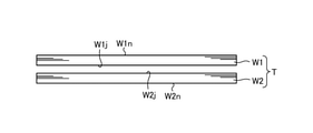
- FIG. 2 is a schematic view showing a state before joining the first substrate and the second substrate according to the embodiment.
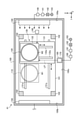
- FIG. 3 is a plan view of the joining device according to the embodiment.
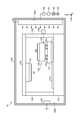
- FIG. 4 is a side view of the joining device according to the embodiment.
- FIG. 5 is a side view of the first holding portion and the second holding portion according to the embodiment.
- FIG. 6 is a perspective view of the second gas supply unit according to the embodiment.
- FIG. 7 is a side sectional view of the second gas supply unit according to the embodiment.
- FIG. 8 is a flowchart showing a procedure of processing executed by the joining system according to the embodiment.
- FIG. 9 is a perspective view of the second gas supply unit according to the modified example.
- FIG. 10 is a side sectional view of the second gas supply unit according to the modified example.
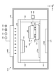
- FIG. 11 is a side view of the joining device according to the modified example.
- the embodiment the joining device, the joining system, and the embodiment for carrying out the joining method according to the present disclosure (hereinafter referred to as “the embodiment”) will be described in detail with reference to the drawings.
- the present disclosure is not limited to this embodiment.
- each embodiment can be appropriately combined as long as the processing contents do not contradict each other.
- the same parts are designated by the same reference numerals, and duplicate explanations are omitted.
- first substrate one substrate
- second substrate the substrate
- the first substrate and the second substrate are joined.
- the second holding portion is moved in the horizontal direction
- the horizontal positions of the first substrate and the second substrate are adjusted
- the second holding portion is further moved in the vertical direction. , Adjust the vertical position of the first substrate and the second substrate.
- the joining accuracy can be improved by reducing the horizontal positional deviation between the first substrate and the second substrate as much as possible.
- FIG. 1 is a schematic diagram showing a configuration of a joining system according to an embodiment.
- FIG. 2 is a schematic view showing a state before joining the first substrate and the second substrate according to the embodiment.
- the bonding system 1 shown in FIG. 1 forms a polymerized substrate T by bonding the first substrate W1 and the second substrate W2 (see FIG. 2).
- the first substrate W1 and the second substrate W2 are single crystal silicon wafers, and a plurality of electronic circuits are formed on the plate surface.
- the first substrate W1 and the second substrate W2 have substantially the same diameter.
- One of the first substrate W1 and the second substrate W2 may be, for example, a substrate on which no electronic circuit is formed.
- the plate surface on the side to be joined to the second substrate W2 is referred to as "joint surface W1j", which is opposite to the joint surface W1j.
- the plate surface is described as "non-bonded surface W1n”.
- the plate surface on the side to be joined to the first substrate W1 is described as “joining surface W2j”
- the plate surface on the side opposite to the joining surface W2j is “non-bonding surface W2n”.
- the joining system 1 includes a loading / unloading station 2 and a processing station 3.
- the carry-in / out station 2 is arranged on the negative direction side of the X-axis of the processing station 3 and is integrally connected to the processing station 3.
- the loading / unloading station 2 includes a mounting table 10 and a transport area 20.
- the mounting table 10 includes a plurality of mounting plates 11.
- Cassettes C1 to C4 for horizontally accommodating a plurality of (for example, 25) substrates are mounted on each mounting plate 11.
- the cassette C1 can accommodate a plurality of first substrates W1
- the cassette C2 can accommodate a plurality of second substrates W2
- the cassette C3 can accommodate a plurality of polymerization substrates T.
- the cassette C4 is, for example, a cassette for collecting a defective substrate.
- the number of cassettes C1 to C4 mounted on the mounting plate 11 is not limited to the one shown in the figure.
- the transport area 20 is arranged adjacent to the X-axis positive direction side of the mounting table 10.
- the transport area 20 is provided with a transport path 21 extending in the X-axis direction and a transport device 22 movable along the transport path 21.
- the transport device 22 can move not only in the Y-axis direction but also in the X-axis direction and can swivel around the Z-axis.
- the transfer device 22 is formed between the cassettes C1 to C4 mounted on the mounting plate 11 and the third processing block G3 of the processing station 3, which will be described later, of the first substrate W1, the second substrate W2, and the polymerization substrate T. Carry out.
- the processing station 3 is provided with, for example, three processing blocks G1, G2, and G3.
- the first processing block G1 is arranged on the back surface side (X-axis positive direction side in FIG. 1) of the processing station 3.
- the second processing block G2 is arranged on the front side of the processing station 3 (the negative direction side of the X axis in FIG. 1)
- the third processing block G3 is on the loading / unloading station 2 side of the processing station 3 (Y in FIG. 1). It is placed on the negative axis side).
- a surface reforming device 30 for modifying the joint surfaces W1j and W2j of the first substrate W1 and the second substrate W2 is arranged in the first processing block G1.
- the surface reformer 30 cuts the bond of SiO2 on the bonding surfaces W1j and W2j of the first substrate W1 and the second substrate W2 to form a single-bonded SiO, so that the bonding surface W1j can be easily hydrophilized thereafter. , W2j is modified.
- oxygen gas or nitrogen gas which is a processing gas
- nitrogen gas or nitrogen gas which is a processing gas
- the oxygen ions or nitrogen ions are irradiated to the joint surfaces W1j and W2j of the first substrate W1 and the second substrate W2, so that the joint surfaces W1j and W2j are plasma-treated and reformed.
- a surface hydrophilization device 40 is arranged in the first treatment block G1.
- the surface hydrophilization device 40 hydrophilizes the joint surfaces W1j and W2j of the first substrate W1 and the second substrate W2 with pure water, and cleans the joint surfaces W1j and W2j.
- the surface hydrophilization device 40 supplies pure water onto the first substrate W1 or the second substrate W2 while rotating the first substrate W1 or the second substrate W2 held by the spin chuck, for example. ..
- the pure water supplied on the first substrate W1 or the second substrate W2 diffuses on the joint surfaces W1j and W2j of the first substrate W1 or the second substrate W2, and the joint surfaces W1j and W2j are hydrophilized. ..
- the surface reforming device 30 and the surface hydrophilizing device 40 are arranged side by side, but the surface hydrophilizing device 40 may be laminated above or below the surface modifying device 30. good.
- a joining device 41 is arranged in the second processing block G2.
- the joining device 41 joins the hydrophilized first substrate W1 and the second substrate W2 by an intermolecular force.
- the specific configuration of the joining device 41 will be described later.
- a transport region 60 is formed in a region surrounded by the first processing block G1, the second processing block G2, and the third processing block G3.
- a transport device 61 is arranged in the transport region 60.
- the transport device 61 has, for example, a transport arm that is movable in the vertical direction, the horizontal direction, and around the vertical axis.
- the transfer device 61 moves in the transfer area 60, and the first substrate W1 and the second are attached to predetermined devices in the first processing block G1, the second processing block G2, and the third processing block G3 adjacent to the transfer area 60.
- the substrate W2 and the polymerization substrate T are conveyed.
- the joining system 1 includes a control device 70.
- the control device 70 controls the operation of the joining system 1.
- the control device 70 is, for example, a computer and includes a control unit and a storage unit (not shown).
- the control unit includes a microcomputer having a CPU (Central Processing Unit), a ROM (Read Only Memory), a RAM (Random Access Memory), an input / output port, and various circuits.
- the CPU of the microcomputer realizes the control described later by reading and executing the program stored in the ROM.
- the storage unit is realized by, for example, a semiconductor memory element such as a RAM or a flash memory, or a storage device such as a hard disk or an optical disk.
- the program may be recorded on a recording medium readable by a computer, and may be installed from the recording medium in the storage unit of the control device 70.
- Recording media that can be read by a computer include, for example, a hard disk (HD), a flexible disk (FD), a compact disk (CD), a magnet optical disk (MO), a memory card, and the like.
- FIG. 3 is a plan view of the joining device 41 according to the embodiment.
- FIG. 4 is a side view of the joining device 41 according to the embodiment.
- the joining device 41 includes a housing 100, a first holding unit 110, a second holding unit 120, a moving unit 130, and a first gas supply unit 140.
- the exhaust unit 150, the first interferometer 160, the second interferometer 170, and the second gas supply unit 180 are provided.
- the housing 100 is, for example, a box body having a rectangular shape in a plan view, and has a first holding unit 110, a second holding unit 120, a moving unit 130, a first gas supply unit 140, an exhaust unit 150, a first interferometer 160, and a first. 2 Accommodates the interferometer 170 and the second gas supply unit 180.
- a mounting table 101 Inside the housing 100, a mounting table 101, a plurality of support columns 102 erected on the upper surface of the mounting table 101, and a ceiling portion 103 supported by the plurality of support columns 102 are arranged.
- the first holding portion 110 sucks and holds the upper surface (non-bonded surface W1n) of the first substrate W1 from above.
- the first holding portion 110 is supported by the ceiling portion 103 (see FIG. 4).
- the second holding portion 120 is provided below the first holding portion 110, and sucks and holds the lower surface (non-bonding surface W2n) of the second substrate W2 from below.
- FIG. 5 is a side view of the first holding portion 110 and the second holding portion 120 according to the embodiment.
- the first holding portion 110 has a main body portion 111.
- the main body 111 is supported by the support member 112.
- the support member 112 and the main body 111 are formed with through holes 113 that penetrate the support member 112 and the main body 111 in the vertical direction.
- the position of the through hole 113 corresponds to the central portion of the first substrate W1 which is sucked and held by the first holding portion 110.
- a pressing pin 191 of the striker 190 which will be described later, is inserted into the through hole 113.
- the striker 190 is arranged on the upper surface of the support member 112, and includes a pressing pin 191, an actuator portion 192, and a linear motion mechanism 193.
- the pressing pin 191 is a columnar member extending along the vertical direction and is supported by the actuator portion 192.
- the actuator unit 192 generates a constant pressure in a fixed direction (here, vertically downward) by air supplied from, for example, an electropneumatic regulator (not shown).
- the actuator unit 192 can control the pressing load applied to the central portion of the first substrate W1 by abutting against the central portion of the first substrate W1 by the air supplied from the electropneumatic regulator. Further, the tip portion of the actuator portion 192 is vertically movable up and down through the through hole 113 by the air from the electropneumatic regulator.
- the actuator unit 192 is supported by the linear motion mechanism 193.
- the linear motion mechanism 193 moves the actuator unit 192 along the vertical direction by, for example, a drive unit having a built-in motor.
- the striker 190 controls the movement of the actuator unit 192 by the linear motion mechanism 193, and controls the pressing load of the first substrate W1 by the pressing pin 191 by the actuator unit 192. As a result, the striker 190 presses the central portion of the first substrate W1 sucked and held by the first holding portion 110 to bring it into contact with the second substrate W2.
- a plurality of pins 114 that come into contact with the upper surface (non-joining surface) of the first substrate W1 are provided.
- the plurality of pins 114 have, for example, a diameter dimension of 0.1 mm to 1 mm and a height of several tens of ⁇ m to several hundreds of ⁇ m.
- the plurality of pins 114 are evenly arranged, for example, at intervals of 2 mm.
- the first holding portion 110 includes a plurality of suction portions for sucking the first substrate W1 in a part of the regions provided with the plurality of pins 114. Specifically, on the lower surface of the main body portion 111 of the first holding portion 110, a plurality of outer suction portions 115 and a plurality of inner suction portions 116 for evacuating and sucking the first substrate W1 are provided.
- the plurality of outer suction portions 115 and the plurality of inner suction portions 116 have an arc-shaped suction region in a plan view.
- the plurality of outer suction portions 115 and the plurality of inner suction portions 116 have the same height as the pin 114.
- the plurality of outer suction portions 115 are arranged on the outer peripheral portion of the main body portion 111.
- the plurality of outer suction portions 115 are connected to a suction device (not shown) such as a vacuum pump, and suck the outer peripheral portion of the first substrate W1 by vacuuming.
- the plurality of inner suction portions 116 are arranged side by side along the circumferential direction in the radial direction of the main body portion 111 with respect to the plurality of outer suction portions 115.
- the plurality of inner suction portions 116 are connected to a suction device (not shown) such as a vacuum pump, and suck the region between the outer peripheral portion and the central portion of the first substrate W1 by vacuuming.
- the second holding unit 120 will be described.
- the second holding portion 120 has a main body portion 121 having the same diameter as the second substrate W2 or a diameter larger than that of the second substrate W2.
- the second holding portion 120 having a diameter larger than that of the second substrate W2 is shown.
- the upper surface of the main body 121 is a facing surface facing the lower surface (non-joining surface W2n) of the second substrate W2.
- a plurality of pins 122 that come into contact with the lower surface (non-joining surface W2n) of the second substrate W2 are provided on the upper surface of the main body portion 121.
- the plurality of pins 122 have, for example, a diameter dimension of 0.1 mm to 1 mm and a height of several tens of ⁇ m to several hundreds of ⁇ m.
- the plurality of pins 122 are evenly arranged at intervals of, for example, 2 mm.
- a lower rib 123 is provided in an annular shape on the outside of the plurality of pins 122.
- the lower rib 123 is formed in an annular shape and supports the outer peripheral portion of the second substrate W2 over the entire circumference.
- the main body portion 121 has a plurality of lower suction ports 124.
- a plurality of lower suction ports 124 are provided in a suction region surrounded by the lower rib 123.
- the plurality of lower suction ports 124 are connected to a suction device (not shown) such as a vacuum pump via a suction tube (not shown).
- the second holding portion 120 decompresses the suction region by vacuuming the suction region surrounded by the lower rib 123 from the plurality of lower suction ports 124. As a result, the second substrate W2 placed on the suction region is sucked and held by the second holding portion 120.
- the second substrate W2 Since the lower rib 123 supports the outer peripheral portion of the lower surface of the second substrate W2 over the entire circumference, the second substrate W2 is appropriately evacuated to the outer peripheral portion. As a result, the entire surface of the second substrate W2 can be adsorbed and held. Further, since the lower surface of the second substrate W2 is supported by the plurality of pins 122, the second substrate W2 is easily peeled off from the second holding portion 120 when the evacuation of the second substrate W2 is released.
- the joining device 41 adsorbs and holds the first substrate W1 on the first holding portion 110, and adsorbs and holds the second substrate W2 on the second holding portion 120. After that, the joining device 41 releases the suction holding of the first substrate W1 by the plurality of inner suction portions 116, and then lowers the pressing pin 191 of the striker 190 to push the central portion of the first substrate W1. As a result, a polymerized substrate T in which the first substrate W1 and the second substrate W2 are bonded is obtained.
- the polymerization substrate T is carried out from the joining device 41 by the fourth transfer device 37.
- the moving unit 130 moves the second holding unit 120 in the horizontal direction.
- the moving unit 130 has a first moving unit 131 that moves the second holding unit 120 along the Y-axis direction and a second moving unit 132 that moves the second holding unit 120 along the X-axis direction. And prepare.
- the first moving portion 131 is attached to a pair of first rails 131a extending along the Y-axis direction, and is configured to be movable along the pair of first rails 131a.
- the pair of first rails 131a is provided on the upper surface of the mounting table 101.
- the second moving portion 132 is attached to a pair of second rails 132a extending along the X-axis direction, and is configured to be movable along the pair of second rails 132a.
- the pair of second rails 132a are provided on the upper surface of the first moving portion 131.
- the second holding portion 120 is attached to the second moving portion 132 and moves integrally with the second moving portion 132. Further, as described above, the second moving portion 132 is attached to the first moving portion 131 via the pair of second rails 132a. Therefore, the moving unit 130 can move the second holding unit 120 along the Y-axis direction by moving the first moving unit 131, and the second holding unit 130 by moving the second moving unit 132. The unit 120 can be moved along the X-axis direction.
- the second moving portion 132 is configured so that the second holding portion 120 can be moved in the vertical direction and can be rotated around the vertical axis.
- the moving unit 130 moves the second holding unit 120 in the X-axis direction, the Y-axis direction, and the ⁇ direction, so that the first substrate W1 held by the first holding unit 110 and the second holding unit 120 are held. Aligning with the second substrate W2 held by the unit 120 in the horizontal direction is performed. Further, the moving unit 130 moves the second holding unit 120 in the Z-axis direction so that the first substrate W1 is held by the first holding unit 110 and the second holding unit 120 is held by the second holding unit 120. Align with the substrate W2 in the vertical direction.
- the moving unit 130 only needs to be able to relatively move the first holding unit 110 and the second holding unit 120 in the X-axis direction, the Y-axis direction, and the ⁇ direction.
- the moving unit 130 may move the first holding unit 110 in the X-axis direction, the Y-axis direction, and the ⁇ direction.
- the moving unit 130 may move the second holding unit 120 in the X-axis direction and the Y-axis direction, and may move the first holding unit 110 in the ⁇ direction.
- the first gas supply unit 140 is an FFU (Fan Filter Unit), and supplies the cleaned first gas to the inside of the housing 100.
- the first gas is, for example, dry air or an inert gas such as nitrogen gas or argon gas.
- the first gas supply unit 140 is connected to the first gas supply source 143 via the first temperature measurement unit 149, the first temperature control unit 141, and the valve 142, and is preset by the first temperature control unit 141.
- the first gas adjusted to the temperature in the embodiment at room temperature (for example, 23 ° C.), is discharged to the inside of the housing 100.
- the first temperature measuring unit 149 measures the temperature of the first gas whose temperature has been adjusted by the first temperature controlling unit 141, and outputs the measurement result to the control unit of the control device 70.
- the first gas supply unit 140 is provided on the side surface 100a orthogonal to the Y-axis direction among the plurality of side surfaces of the housing 100. Then, the first gas supply unit 140 discharges the first gas along the Y-axis direction (specifically, the Y-axis positive direction).
- the exhaust unit 150 is provided on the side surface 100b facing the side surface 100a to which the first gas supply unit 140 is attached, among the plurality of side surfaces of the housing 100.
- the exhaust unit 150 is connected to a suction device (not shown) such as a vacuum pump, and uses the suction force of the suction device to exhaust the inside of the housing 100.
- the first gas supply unit 140 provided on one side surface 100a of the housing 100 and the exhaust unit 150 provided on the other side surface 100b facing the side surface 100a. Therefore, a side flow is formed inside the housing 100.
- the first interferometer 160 and the second interferometer 170 are, for example, laser interferometers, and measure the horizontal distance to the second moving unit 132 by irradiating the side surface of the second moving unit 132 with a laser beam.
- the first interferometer 160 is arranged between the second moving unit 132 and the first gas supply unit 140, and is the discharge direction of the first gas by the first gas supply unit 140, in other words, the flow direction of the side flow. Irradiate the laser beam along the Y-axis direction. As a result, the first interferometer 160 measures the horizontal distance along the Y-axis direction from the reference point in the first interferometer 160 to the second moving portion 132.
- the second interferometer 170 is arranged between the side surface 100c orthogonal to the X-axis direction and the second moving portion 132 among the plurality of side surfaces of the housing 100.
- the second interferometer 170 irradiates the laser beam along the X-axis direction orthogonal to the flow direction of the side flow.
- the second interferometer 170 measures the horizontal distance along the X-axis direction from the reference point in the second interferometer 170 to the second moving portion 132.
- the first interferometer 160 and the second interferometer 170 do not necessarily need to irradiate the second moving unit 132 with a laser beam, and are objects that move together with the second moving unit 132 or the second moving unit 132.
- the laser beam may be applied to the object.
- the first interferometer 160 and the second interferometer 170 may measure the horizontal distance to the second holding portion 120 by irradiating the second holding portion 120 with a laser beam. Further, the first interferometer 160 and the second interferometer 170 irradiate another member provided on the second moving portion 132 or the second moving portion 132 with a laser beam to obtain a horizontal distance to the other member. May be measured.
- the light emitted from the first interferometer 160 and the second interferometer 170 does not necessarily have to be laser light, and may be directional light having a certain period.
- the inventor of the present application measured the length measurement error in the joining device 41. As a result, the error was small in the length measurement in the direction parallel to the side flow flow, while the error was large in the length measurement in the direction orthogonal to the side flow flow.
- the measurement error due to the side flow is reduced by protecting the light of the second interferometer 170 irradiated so as to cross the side flow by the spot air flow having a stable temperature. And said.
- the second gas supply unit 180 supplies the second gas to the space between the second moving unit 132 and the second interferometer 170 to which the laser beam from the second interferometer 170 is irradiated. Specifically, the second gas supply unit 180 discharges the second gas in parallel with the optical path LP so as to cover the optical path LP of the light emitted from the second interferometer 170.
- the second gas is, for example, dry air or an inert gas such as nitrogen gas or argon gas.
- the second gas supply unit 180 is connected to the second gas supply source 183 via the second temperature measurement unit 189, the second temperature control unit 181 and the valve 182, and is preset by the second temperature control unit 181.
- the second gas adjusted to the temperature in the embodiment at room temperature (for example, 23 ° C.), is discharged to the inside of the housing 100.
- the second temperature measuring unit 189 measures the temperature of the second gas whose temperature has been adjusted by the second temperature controlling unit 181 and outputs the measurement result to the control unit of the control device 70.
- the first gas and the second gas are adjusted to the same temperature by the first temperature control unit 141 and the second temperature control unit 181.
- the control unit of the control device 70 controls the second temperature control unit 181 based on the measurement result of the first temperature measurement unit 149, so that the temperature of the second gas is the same as the temperature of the first gas. Adjust to temperature. Further, the control unit of the control device 70 adjusts the temperature of the first gas to the same temperature as the temperature of the second gas by controlling the first temperature control unit 141 based on the measurement result of the second temperature measurement unit 189. You may.
- the joining device 41 includes the first temperature measuring unit 149 and the second temperature measuring unit 189 has been described, but the joining device 41 includes the first temperature measuring unit 149 and the second temperature measuring unit. It suffices to have at least one of 189. Further, here, an example in which the joining device 41 includes the first temperature control section 141 and the second temperature control section 181 has been described, but the joining device 41 includes the first temperature control section 141 and the second temperature control section. It suffices to have at least one of 181.
- the joining device 41 may include the second temperature control unit 181 in the second gas supply unit 180.
- the joining device 41 may include the first temperature control unit 141 in the first gas supply unit 140.
- FIG. 6 is a perspective view of the second gas supply unit 180 according to the embodiment.
- FIG. 7 is a side sectional view of the second gas supply unit 180 according to the embodiment.
- the second gas supply unit 180 includes an accommodating unit 184, an introduction unit 185, and a nozzle 186.
- the accommodating section 184 accommodates the second interferometer 170.
- the introduction portion 185 is a tubular portion that communicates the inside and the outside of the accommodating portion 184, and is provided on, for example, the upper surface of the accommodating portion 184.
- the introduction unit 185 is connected to the second gas supply source 183 via the second temperature control unit 181 and the valve 182, and introduces the second gas into the accommodating unit 184.
- the nozzle 186 is provided on the side surface of the accommodating portion 184 facing the second moving portion 132 (see FIG. 3), and discharges the second gas introduced into the accommodating portion 184 from the introduction portion 185.
- the nozzle 186 includes a first opening 186a1 and a second opening 186b1.
- the nozzle 186 includes a cylindrical first member 186a and a second member 186b that open along the X-axis direction, and the first member 186a is included in the second member 186b. Be placed.
- the first opening 186a1 corresponds to the opening of the first member 186a.
- the second opening 186b1 corresponds to a gap formed between the first member 186a and the second member 186b.
- the base end portion of the first member 186a is in contact with the second interferometer 170 so as to surround the light irradiation portion of the second interferometer 170. Therefore, the light emitted from the second interferometer 170 passes through the first opening 186a1 and is applied to the second moving portion 132.
- the second gas supply unit 180 discharges the second gas from the second opening 186b1.
- the second gas discharged from the second opening 186b1 flows in parallel with the light emitted from the second interferometer 170 so as to cover the light emitted from the second interferometer 170.
- the temperature of the second gas is adjusted by the second temperature control unit 181 and the temperature is stable. By covering the light emitted from the second interferometer 170 with the second gas, the light can be protected from the surrounding thermal environment.
- the second interferometer 170 that irradiates the light in the direction orthogonal to the side flow is housed inside the second gas supply unit 180. Then, in the joining device 41 according to the embodiment, the light emitted from the second interferometer 170 is protected by the air flow of the second gas discharged from the second gas supply unit 180.
- the joining device 41 By reducing the error in the measurement result of the second interferometer 170, the positioning accuracy of the second substrate W2 is improved. Therefore, according to the joining device 41 according to the embodiment, it is possible to improve the joining accuracy of the first substrate W1 and the second substrate W2.
- a method of physically covering the optical path of the light emitted from the second interferometer 170 with a tubular cover body can be considered.
- this method it is necessary to move the cover body in accordance with the movement of the second holding portion 120, which may complicate the structure.
- the movable range of the second holding portion 120 is likely to be limited.
- the light emitted from the second interferometer 170 is protected by the air flow. Therefore, the movable range of the second holding portion 120 is less likely to be limited and the structure is simple as compared with the case of protecting with a physical cover body. Further, by using the temperature-controlled airflow, the temperature stability is excellent as compared with the protection by the cover body.
- the second gas supply unit 180 discharges the second gas at a wind speed faster than the wind speed of the first gas discharged from the first gas supply unit 140. This makes it possible to more reliably protect the light emitted from the second interferometer 170.
- the joining device 41 includes a transition, a position adjusting mechanism, a reversing mechanism, and the like.
- the transition temporarily places the first substrate W1, the second substrate W2, and the polymerization substrate T.
- the position adjusting mechanism adjusts the horizontal orientation of the first substrate W1 and the second substrate W2.
- the inversion mechanism inverts the front and back of the first substrate W1.
- FIG. 8 is a flowchart showing a procedure of processing executed by the joining system 1 according to the embodiment. The various processes shown in FIG. 8 are executed based on the control by the control device 70.
- a cassette C1 containing a plurality of first boards W1, a cassette C2 containing a plurality of second boards W2, and an empty cassette C3 are placed on a predetermined mounting plate 11 of the loading / unloading station 2.
- the first substrate W1 in the cassette C1 is taken out by the transfer device 22, and is transferred to the transition device arranged in the third processing block G3.
- the first substrate W1 is transported to the surface reforming device 30 of the first processing block G1 by the transport device 61.
- oxygen gas which is a processing gas
- the oxygen ions are irradiated to the joint surface of the first substrate W1, and the joint surface is subjected to plasma treatment.
- the joint surface of the first substrate W1 is modified (step S101).
- the first substrate W1 is conveyed to the surface hydrophilization device 40 of the first processing block G1 by the transfer device 61.
- the surface hydrophilization device 40 pure water is supplied onto the first substrate W1 while rotating the first substrate W1 held by the spin chuck. As a result, the bonding surface of the first substrate W1 is made hydrophilic. Further, the joint surface of the first substrate W1 is washed with the pure water (step S102).
- the first substrate W1 is conveyed to the joining device 41 of the second processing block G2 by the conveying device 61.
- the first substrate W1 carried into the joining device 41 is conveyed to the position adjusting mechanism via the transition, and the horizontal orientation is adjusted by the position adjusting mechanism (step S103).
- the first substrate W1 is handed over from the position adjusting mechanism to the inversion mechanism, and the front and back surfaces of the first substrate W1 are inverted by the inversion mechanism (step S104). Specifically, the joint surface W1j of the first substrate W1 is directed downward. Subsequently, the first substrate W1 is delivered from the reversing mechanism to the first holding portion 110, and the first substrate W1 is sucked and held by the first holding portion 110.
- the processing of the second substrate W2 is performed in duplicate with the processing of steps S101 to S105 for the first substrate W1.
- the second substrate W2 in the cassette C2 is taken out by the transfer device 22, and is transferred to the transition device arranged in the third processing block G3.
- the second substrate W2 is transported to the surface reforming device 30 by the transport device 61, and the joint surface W2j of the second substrate W2 is reformed (step S106).
- the second substrate W2 is conveyed to the surface hydrophilization device 40 by the transfer device 61, the joint surface W2j of the second substrate W2 is hydrophilized, and the joint surface is washed (step S107).
- the second substrate W2 is conveyed to the joining device 41 by the conveying device 61.
- the second substrate W2 carried into the joining device 41 is conveyed to the position adjusting mechanism via the transition.
- the horizontal orientation of the second substrate W2 is adjusted by the position adjusting mechanism (step S108).
- the second substrate W2 is conveyed to the second holding portion 120, and is adsorbed and held by the second holding portion 120 with the notch portion oriented in a predetermined direction (step S109).
- step S110 the horizontal position adjustment between the first substrate W1 held by the first holding portion 110 and the second substrate W2 held by the second holding portion 120 is performed.
- the center position (X coordinate and Y coordinate) of the second substrate W2 is specified based on the measurement results of the first interferometer 160 and the second interferometer 170. Then, the second substrate W2 is moved by using the first moving portion 131 and the second moving portion 132 so that the center position of the second substrate W2 coincides with the center position of the first substrate W1.
- step S111 the first substrate W1 and the second substrate W2 are joined.
- the vertical positions of the first substrate W1 held by the first holding portion 110 and the second substrate W2 held by the second holding portion 120 are adjusted. Specifically, the second moving portion 132 moves the second holding portion 120 vertically upward to bring the second substrate W2 closer to the first substrate W1.
- the central portion of the first substrate W1 is pressed by lowering the pressing pin 191 of the striker 190.
- the bonding surface W1j of the first substrate W1 and the bonding surface W2j of the second substrate W2 are hydrophilized, the hydrophilic groups between the bonding surfaces W1j and W2j are hydrogen-bonded, and the bonding surfaces W1j and W2j are firmly bonded to each other. Be joined. In this way, the junction region is formed.
- a bonding wave is generated between the first substrate W1 and the second substrate W2 in which the bonding region expands from the central portion of the first substrate W1 and the second substrate W2 toward the outer peripheral portion.
- the suction holding of the first substrate W1 by the plurality of outer suction portions 115 is released (step S114).
- the outer peripheral portion of the first substrate W1 that has been sucked and held by the outer suction portion 115 falls.
- the bonding surface W1j of the first substrate W1 and the bonding surface W2j of the second substrate W2 are in contact with each other on the entire surface, and the polymerization substrate T is formed.
- the pressing pin 191 is raised to the first holding portion 110 to release the suction holding of the second substrate W2 by the second holding portion 120.
- the polymerization substrate T is carried out from the joining device 41 by the transport device 61. In this way, a series of joining processes is completed.
- FIG. 9 is a perspective view of the second gas supply unit according to the modified example.
- FIG. 10 is a side sectional view of the second gas supply unit according to the modified example.
- the second gas supply unit 180A includes a storage unit 184A, an introduction unit 185A, and a nozzle 186A.
- the accommodating unit 184A accommodates the second interferometer 170.
- the introduction portion 185A is a cylindrical portion that communicates the inside and the outside of the accommodating portion 184A, and is provided on the side surface of the accommodating portion 184A, for example.
- the introduction unit 185A is connected to the second gas supply source 183 via the second temperature control unit 181 and the valve 182, and introduces the second gas into the accommodating unit 184A.
- the nozzle 186A is provided on the side surface of the accommodating portion 184A facing the second moving portion 132, and discharges the second gas introduced into the accommodating portion 184A from the introduction portion 185A.
- the nozzle 186A has, for example, a single opening 186A1 and discharges a second gas from the opening 186A1 and allows light emitted from the second interferometer 170 to pass through.
- the second gas discharged from the opening 186A1 flows in parallel with the light emitted from the second interferometer 170 so as to cover the light emitted from the second interferometer 170. As a result, the light emitted from the second interferometer 170 is protected by the second gas.
- the opening 186A1 of the nozzle 186A extends in a slit shape along the Y-axis direction, which is the discharge direction of the first gas, that is, the flow direction of the side flow.
- the second interferometer 170 is arranged at a position facing the downstream end of the opening 186A1 inside the accommodating portion 184A, and irradiates light from the downstream end of the opening 186A1.
- the second interferometer 170 may be arranged at least on the downstream side of the side flow from the central portion in the extending direction of the opening 186A1.
- a slit-shaped opening 186A1 extending along the flow direction of the side flow is provided in the second gas supply unit 180A, and the second gas is supplied from the upstream side of the light emitted from the second interferometer 170. It may be discharged. This makes it possible to more reliably protect the light emitted from the second interferometer 170.
- FIG. 11 is a side view of the joining device according to the modified example.
- the joining device 41B includes a first gas supply unit 140B and an exhaust unit 150B.
- the first gas supply unit 140B is provided on the upper surface of the housing 100 and discharges the first gas vertically downward. Further, the exhaust portion 150B is provided on the bottom surface of the housing 100.
- the joining device 41B may form a downflow inside the housing 100 by using the first gas supply unit 140B and the exhaust unit 150B.
- the joining device 41B may also provide the second gas supply unit 180 in the first interferometer 160 to protect the light emitted from the first interferometer 160 by the air flow of the second gas.
- the interferometer may irradiate light in a direction intersecting the discharge direction of the first gas by the first gas supply unit.
- the second gas supply unit may discharge the second gas in parallel with the light, that is, in a direction intersecting the side flow or the down flow.
- the second gas supply unit may discharge the second gas from a direction intersecting with the light emitted from the interferometer, specifically, a direction orthogonal to the light.
- the second gas supply unit discharges the second gas to the optical path from the upstream side of the side flow or the downflow rather than the optical path of the light emitted from the interferometer. That is, it is preferable that the second gas supply unit discharges the second gas in the same direction as the side flow or the down flow.
- the joining device (as an example, 41, 41A, 41B) according to the embodiment is a joining device for joining the substrates to each other, and has a first holding portion (as an example, a first holding portion 110).
- the second holding unit (for example, the second holding unit 120), the moving unit (for example, the moving unit 130), the housing (for example, the housing 100), and the interferometer (for example, the first interference).
- the first holding portion sucks and holds the first substrate (for example, the first substrate W1) from above.
- the second holding portion sucks and holds the second substrate (for example, the second substrate W2) from below.
- the moving portion moves one of the first holding portion and the second holding portion in the horizontal direction with respect to the other.
- the housing accommodates the first holding portion, the second holding portion and the moving portion.
- the interferometer is placed inside the housing and measures the horizontal distance to the one or the object by irradiating the object moving with the one or the object with light (as an example, a laser beam).
- the first gas supply unit supplies the cleaned first gas to the inside of the housing.
- the second gas supply unit supplies the second gas to the space between the one or the object and the interferometer, which is irradiated with light.
- the joining device it is possible to improve the joining accuracy between the boards in the joining technique for joining the boards.
- the second gas supply unit may discharge the second gas parallel to the optical path so as to cover the optical path of light. This makes it possible to appropriately protect the light emitted from the interferometer.
- the interferometer may irradiate light in a direction intersecting the discharge direction of the first gas by the first gas supply unit, and the second gas supply unit may discharge the second gas in the direction of intersection.
- An interferometer that irradiates light in a direction intersecting the discharge direction of the first gas by the first gas supply unit is susceptible to the temperature of the first gas. Therefore, by protecting the light emitted in the bright direction by using the air flow of the second gas, the light emitted from the interferometer can be appropriately protected.
- the first gas supply unit (for example, the first gas supply unit 140) is provided on the side surface (for example, the side surface 100a) of the housing, and the first gas is directed in the first horizontal direction (for example, the Y-axis direction). It may be discharged.
- the interferometer for example, the second interferometer 170
- the second gas supply unit is the second. 2
- the second gas may be discharged in the horizontal direction.
- the first gas supply unit (for example, the first gas supply unit 140B) may be provided on the upper surface of the housing and discharge the first gas in the vertical direction (for example, the Z-axis direction).
- the second gas supply unit includes an accommodating unit (for example, accommodating unit 184, 184A) for accommodating the interferometer, and an introduction unit (for example, introduction unit 185, 185A) for introducing the second gas into the accommodating unit.
- a nozzle as an example, nozzles 186, 186A
- the interferometer may irradiate light from the inside of the accommodating portion through the nozzle.
- the second gas supply unit can discharge the second gas in parallel with the optical path so as to cover the optical path of the light.
- the nozzle (as an example, the nozzle 186) has a first opening (for example, the first opening 186a1) through which light passes and an annular second opening (for example, the second opening) provided so as to surround the first opening. It may be provided with 186a2).
- the second gas supply unit may discharge the second gas from the second opening.
- the nozzle (as an example, the nozzle 186A) may have an opening (as an example, an opening 186A1) extending along the discharge direction of the first gas.
- the interferometer may irradiate light from the downstream side of the aperture. In this way, by discharging the second gas from the upstream side of the light emitted from the interferometer, the light emitted from the interferometer can be protected more reliably.
- the second gas supply unit may discharge the second gas at a wind speed faster than the wind speed of the first gas discharged from the first gas supply unit. This makes it possible to appropriately protect the light emitted from the interferometer from the air flow of the first gas.
- the first gas supply unit may include a first temperature measurement unit that measures the temperature of the first gas
- the second gas supply unit may include a second temperature control unit that adjusts the temperature of the second gas.
- the joining device controls the second temperature control section based on the measurement result of the first temperature measuring section, so that the temperature of the second gas is the same as the temperature of the first gas. Further, a control unit for adjusting the temperature may be provided.
- the first gas supply unit may include a first temperature control unit that adjusts the temperature of the first gas
- the second gas supply unit may include a second temperature measurement unit that measures the temperature of the second gas.
- the joining device adjusts the temperature of the first gas to the same temperature as the temperature of the second gas by controlling the first temperature control unit based on the measurement result of the second temperature measuring unit.
- a control unit may be further provided.
- Joining system 30 Surface reforming device 40: Surface hydrophilization device 41: Joining device 70: Control device 100: Housing 101: Mounting table 102: Strut part 103: Ceiling part 110: First holding part 120: Second Holding part 130: Moving part 131: First moving part 131a: First rail 132: Second moving part 132a: Second rail 140: First gas supply part 141: First temperature control part 150: Exhaust part 160: First Interferometer 170: Second interferometer 180: Second gas supply unit 181: Second temperature control unit 184: Containment unit 185: Introduction unit 186: Nozzle 186a1: First opening 186b1: Second opening LP: Optical path T: Polymerization substrate W1: 1st board W2: 2nd board
Landscapes
- Container, Conveyance, Adherence, Positioning, Of Wafer (AREA)
- Pressure Welding/Diffusion-Bonding (AREA)
- Engineering & Computer Science (AREA)
- Manufacturing & Machinery (AREA)
- Physics & Mathematics (AREA)
- General Physics & Mathematics (AREA)
Abstract
Priority Applications (4)
| Application Number | Priority Date | Filing Date | Title |
|---|---|---|---|
| CN202180048136.8A CN115769341B (zh) | 2020-07-17 | 2021-07-05 | 接合装置、接合系统以及接合方法 |
| KR1020237005149A KR102826407B1 (ko) | 2020-07-17 | 2021-07-05 | 접합 장치, 접합 시스템 및 접합 방법 |
| JP2022536265A JP7341348B2 (ja) | 2020-07-17 | 2021-07-05 | 接合装置、接合システムおよび接合方法 |
| US18/005,392 US12538825B2 (en) | 2020-07-17 | 2021-07-05 | Bonding apparatus, bonding system, and bonding method |
Applications Claiming Priority (2)
| Application Number | Priority Date | Filing Date | Title |
|---|---|---|---|
| JP2020122588 | 2020-07-17 | ||
| JP2020-122588 | 2020-07-17 |
Publications (1)
| Publication Number | Publication Date |
|---|---|
| WO2022014384A1 true WO2022014384A1 (fr) | 2022-01-20 |
Family
ID=79555398
Family Applications (1)
| Application Number | Title | Priority Date | Filing Date |
|---|---|---|---|
| PCT/JP2021/025248 Ceased WO2022014384A1 (fr) | 2020-07-17 | 2021-07-05 | Dispositif de liaison, système de liaison et procédé de liaison |
Country Status (5)
| Country | Link |
|---|---|
| US (1) | US12538825B2 (fr) |
| JP (1) | JP7341348B2 (fr) |
| KR (1) | KR102826407B1 (fr) |
| CN (1) | CN115769341B (fr) |
| WO (1) | WO2022014384A1 (fr) |
Cited By (1)
| Publication number | Priority date | Publication date | Assignee | Title |
|---|---|---|---|---|
| WO2026048179A1 (fr) * | 2024-08-27 | 2026-03-05 | 株式会社Screenホールディングス | Dispositif de traitement de substrat |
Families Citing this family (2)
| Publication number | Priority date | Publication date | Assignee | Title |
|---|---|---|---|---|
| JP7655642B2 (ja) * | 2021-05-24 | 2025-04-02 | 東京エレクトロン株式会社 | 接合装置、及び接合方法 |
| JP2026008445A (ja) * | 2024-07-05 | 2026-01-19 | 株式会社Screenホールディングス | 基板接合装置 |
Citations (4)
| Publication number | Priority date | Publication date | Assignee | Title |
|---|---|---|---|---|
| JP2011049318A (ja) * | 2009-08-26 | 2011-03-10 | Nikon Corp | 基板重ね合わせ装置およびデバイスの製造方法 |
| WO2014064944A1 (fr) * | 2012-10-26 | 2014-05-01 | 株式会社ニコン | Appareil de collage de substrat, appareil d'alignement, procédé de collage de substrat, procédé d'alignement, et procédé de fabrication de dispositif à semi-conducteur stratifié |
| JP2015018926A (ja) * | 2013-07-10 | 2015-01-29 | 東京エレクトロン株式会社 | 接合装置、接合システム、接合方法、プログラム及びコンピュータ記憶媒体 |
| WO2018088094A1 (fr) * | 2016-11-09 | 2018-05-17 | 東京エレクトロン株式会社 | Dispositif de liaison, système de liaison, procédé de liaison, et support d'enregistrement pour ordinateur |
Family Cites Families (7)
| Publication number | Priority date | Publication date | Assignee | Title |
|---|---|---|---|---|
| JPH08285520A (ja) * | 1995-04-12 | 1996-11-01 | Nikon Corp | 測定装置 |
| JPH1092735A (ja) * | 1996-09-13 | 1998-04-10 | Nikon Corp | 露光装置 |
| JP3372782B2 (ja) * | 1996-10-04 | 2003-02-04 | キヤノン株式会社 | 走査ステージ装置および走査型露光装置 |
| KR20070048722A (ko) * | 2004-09-10 | 2007-05-09 | 가부시키가이샤 니콘 | 스테이지 장치 및 노광 장치 |
| CN104111589A (zh) * | 2007-07-18 | 2014-10-22 | 株式会社尼康 | 测量方法、载台装置、及曝光装置 |
| JP2011133398A (ja) * | 2009-12-25 | 2011-07-07 | Nikon Corp | 移動体装置、露光装置、デバイス製造方法、及び移動体の位置情報計測方法 |
| WO2018009953A1 (fr) * | 2016-07-13 | 2018-01-18 | Technische Universität Wien | Appareil et procédé d'interférométrie photothermique |
-
2021
- 2021-07-05 WO PCT/JP2021/025248 patent/WO2022014384A1/fr not_active Ceased
- 2021-07-05 CN CN202180048136.8A patent/CN115769341B/zh active Active
- 2021-07-05 JP JP2022536265A patent/JP7341348B2/ja active Active
- 2021-07-05 US US18/005,392 patent/US12538825B2/en active Active
- 2021-07-05 KR KR1020237005149A patent/KR102826407B1/ko active Active
Patent Citations (4)
| Publication number | Priority date | Publication date | Assignee | Title |
|---|---|---|---|---|
| JP2011049318A (ja) * | 2009-08-26 | 2011-03-10 | Nikon Corp | 基板重ね合わせ装置およびデバイスの製造方法 |
| WO2014064944A1 (fr) * | 2012-10-26 | 2014-05-01 | 株式会社ニコン | Appareil de collage de substrat, appareil d'alignement, procédé de collage de substrat, procédé d'alignement, et procédé de fabrication de dispositif à semi-conducteur stratifié |
| JP2015018926A (ja) * | 2013-07-10 | 2015-01-29 | 東京エレクトロン株式会社 | 接合装置、接合システム、接合方法、プログラム及びコンピュータ記憶媒体 |
| WO2018088094A1 (fr) * | 2016-11-09 | 2018-05-17 | 東京エレクトロン株式会社 | Dispositif de liaison, système de liaison, procédé de liaison, et support d'enregistrement pour ordinateur |
Cited By (1)
| Publication number | Priority date | Publication date | Assignee | Title |
|---|---|---|---|---|
| WO2026048179A1 (fr) * | 2024-08-27 | 2026-03-05 | 株式会社Screenホールディングス | Dispositif de traitement de substrat |
Also Published As
| Publication number | Publication date |
|---|---|
| JP7341348B2 (ja) | 2023-09-08 |
| CN115769341A (zh) | 2023-03-07 |
| US12538825B2 (en) | 2026-01-27 |
| KR102826407B1 (ko) | 2025-06-27 |
| KR20230041022A (ko) | 2023-03-23 |
| US20230275062A1 (en) | 2023-08-31 |
| JPWO2022014384A1 (fr) | 2022-01-20 |
| CN115769341B (zh) | 2026-02-10 |
Similar Documents
| Publication | Publication Date | Title |
|---|---|---|
| JP6908757B2 (ja) | 接合装置、接合システム、接合方法及びコンピュータ記憶媒体 | |
| WO2022014384A1 (fr) | Dispositif de liaison, système de liaison et procédé de liaison | |
| JP7488062B2 (ja) | 接合装置、接合システム、接合方法および記憶媒体 | |
| KR20190116207A (ko) | 접합 장치 및 접합 시스템 | |
| JP6883690B2 (ja) | 接合装置、接合システム、接合方法及びコンピュータ記憶媒体 | |
| JP7383133B2 (ja) | 接合システム | |
| JP2015018919A (ja) | 接合装置、接合システム、接合方法、プログラム及びコンピュータ記憶媒体 | |
| TW202127512A (zh) | 基板貼合裝置及方法 | |
| JP2015018926A (ja) | 接合装置、接合システム、接合方法、プログラム及びコンピュータ記憶媒体 | |
| JP2017073455A (ja) | 接合システム | |
| US20230326797A1 (en) | Bonding apparatus, bonding system, bonding method, and recording medium | |
| JP7655642B2 (ja) | 接合装置、及び接合方法 | |
| US20260130136A1 (en) | Bonding system | |
| CN120998805A (zh) | 基板保持装置和接合系统 | |
| KR20240137472A (ko) | 접합 장치, 접합 시스템 및 접합 방법 | |
| JP2026011563A (ja) | 載置台、接合装置および接合システム | |
| JP2006344986A (ja) | 塗布、現像装置及びパターン形成方法 |
Legal Events
| Date | Code | Title | Description |
|---|---|---|---|
| 121 | Ep: the epo has been informed by wipo that ep was designated in this application |
Ref document number: 21843009 Country of ref document: EP Kind code of ref document: A1 |
|
| ENP | Entry into the national phase |
Ref document number: 2022536265 Country of ref document: JP Kind code of ref document: A |
|
| ENP | Entry into the national phase |
Ref document number: 20237005149 Country of ref document: KR Kind code of ref document: A |
|
| NENP | Non-entry into the national phase |
Ref country code: DE |
|
| 122 | Ep: pct application non-entry in european phase |
Ref document number: 21843009 Country of ref document: EP Kind code of ref document: A1 |
|
| WWG | Wipo information: grant in national office |
Ref document number: 18005392 Country of ref document: US |