WO2022014652A1 - Système de régulation d'humidité, dispositif d'adsorption et de désorption, dispositif de régulation d'humidité et procédé de régulation d'humidité - Google Patents
Système de régulation d'humidité, dispositif d'adsorption et de désorption, dispositif de régulation d'humidité et procédé de régulation d'humidité Download PDFInfo
- Publication number
- WO2022014652A1 WO2022014652A1 PCT/JP2021/026523 JP2021026523W WO2022014652A1 WO 2022014652 A1 WO2022014652 A1 WO 2022014652A1 JP 2021026523 W JP2021026523 W JP 2021026523W WO 2022014652 A1 WO2022014652 A1 WO 2022014652A1
- Authority
- WO
- WIPO (PCT)
- Prior art keywords
- gas
- adsorbent
- humidity control
- moisture
- air passage
- Prior art date
- Legal status (The legal status is an assumption and is not a legal conclusion. Google has not performed a legal analysis and makes no representation as to the accuracy of the status listed.)
- Ceased
Links
Images








Classifications
-
- A—HUMAN NECESSITIES
- A01—AGRICULTURE; FORESTRY; ANIMAL HUSBANDRY; HUNTING; TRAPPING; FISHING
- A01G—HORTICULTURE; CULTIVATION OF VEGETABLES, FLOWERS, RICE, FRUIT, VINES, HOPS OR SEAWEED; FORESTRY; WATERING
- A01G7/00—Botany in general
- A01G7/02—Treatment of plants with carbon dioxide
-
- A—HUMAN NECESSITIES
- A01—AGRICULTURE; FORESTRY; ANIMAL HUSBANDRY; HUNTING; TRAPPING; FISHING
- A01G—HORTICULTURE; CULTIVATION OF VEGETABLES, FLOWERS, RICE, FRUIT, VINES, HOPS OR SEAWEED; FORESTRY; WATERING
- A01G9/00—Cultivation in receptacles, forcing-frames or greenhouses; Edging for beds, lawn or the like
- A01G9/18—Greenhouses for treating plants with carbon dioxide or the like
-
- B—PERFORMING OPERATIONS; TRANSPORTING
- B01—PHYSICAL OR CHEMICAL PROCESSES OR APPARATUS IN GENERAL
- B01D—SEPARATION
- B01D53/00—Separation of gases or vapours; Recovering vapours of volatile solvents from gases; Chemical or biological purification of waste gases, e.g. engine exhaust gases, smoke, fumes, flue gases, aerosols
- B01D53/02—Separation of gases or vapours; Recovering vapours of volatile solvents from gases; Chemical or biological purification of waste gases, e.g. engine exhaust gases, smoke, fumes, flue gases, aerosols by adsorption, e.g. preparative gas chromatography
- B01D53/04—Separation of gases or vapours; Recovering vapours of volatile solvents from gases; Chemical or biological purification of waste gases, e.g. engine exhaust gases, smoke, fumes, flue gases, aerosols by adsorption, e.g. preparative gas chromatography with stationary adsorbents
-
- B—PERFORMING OPERATIONS; TRANSPORTING
- B01—PHYSICAL OR CHEMICAL PROCESSES OR APPARATUS IN GENERAL
- B01D—SEPARATION
- B01D53/00—Separation of gases or vapours; Recovering vapours of volatile solvents from gases; Chemical or biological purification of waste gases, e.g. engine exhaust gases, smoke, fumes, flue gases, aerosols
- B01D53/02—Separation of gases or vapours; Recovering vapours of volatile solvents from gases; Chemical or biological purification of waste gases, e.g. engine exhaust gases, smoke, fumes, flue gases, aerosols by adsorption, e.g. preparative gas chromatography
- B01D53/06—Separation of gases or vapours; Recovering vapours of volatile solvents from gases; Chemical or biological purification of waste gases, e.g. engine exhaust gases, smoke, fumes, flue gases, aerosols by adsorption, e.g. preparative gas chromatography with moving adsorbents, e.g. rotating beds
-
- B—PERFORMING OPERATIONS; TRANSPORTING
- B01—PHYSICAL OR CHEMICAL PROCESSES OR APPARATUS IN GENERAL
- B01D—SEPARATION
- B01D53/00—Separation of gases or vapours; Recovering vapours of volatile solvents from gases; Chemical or biological purification of waste gases, e.g. engine exhaust gases, smoke, fumes, flue gases, aerosols
- B01D53/14—Separation of gases or vapours; Recovering vapours of volatile solvents from gases; Chemical or biological purification of waste gases, e.g. engine exhaust gases, smoke, fumes, flue gases, aerosols by absorption
-
- B—PERFORMING OPERATIONS; TRANSPORTING
- B01—PHYSICAL OR CHEMICAL PROCESSES OR APPARATUS IN GENERAL
- B01D—SEPARATION
- B01D53/00—Separation of gases or vapours; Recovering vapours of volatile solvents from gases; Chemical or biological purification of waste gases, e.g. engine exhaust gases, smoke, fumes, flue gases, aerosols
- B01D53/22—Separation of gases or vapours; Recovering vapours of volatile solvents from gases; Chemical or biological purification of waste gases, e.g. engine exhaust gases, smoke, fumes, flue gases, aerosols by diffusion
-
- B—PERFORMING OPERATIONS; TRANSPORTING
- B01—PHYSICAL OR CHEMICAL PROCESSES OR APPARATUS IN GENERAL
- B01D—SEPARATION
- B01D53/00—Separation of gases or vapours; Recovering vapours of volatile solvents from gases; Chemical or biological purification of waste gases, e.g. engine exhaust gases, smoke, fumes, flue gases, aerosols
- B01D53/26—Drying gases or vapours
-
- F—MECHANICAL ENGINEERING; LIGHTING; HEATING; WEAPONS; BLASTING
- F24—HEATING; RANGES; VENTILATING
- F24F—AIR-CONDITIONING; AIR-HUMIDIFICATION; VENTILATION; USE OF AIR CURRENTS FOR SCREENING
- F24F6/00—Air-humidification, e.g. cooling by humidification
-
- Y—GENERAL TAGGING OF NEW TECHNOLOGICAL DEVELOPMENTS; GENERAL TAGGING OF CROSS-SECTIONAL TECHNOLOGIES SPANNING OVER SEVERAL SECTIONS OF THE IPC; TECHNICAL SUBJECTS COVERED BY FORMER USPC CROSS-REFERENCE ART COLLECTIONS [XRACs] AND DIGESTS
- Y02—TECHNOLOGIES OR APPLICATIONS FOR MITIGATION OR ADAPTATION AGAINST CLIMATE CHANGE
- Y02C—CAPTURE, STORAGE, SEQUESTRATION OR DISPOSAL OF GREENHOUSE GASES [GHG]
- Y02C20/00—Capture or disposal of greenhouse gases
- Y02C20/40—Capture or disposal of greenhouse gases of CO2
-
- Y—GENERAL TAGGING OF NEW TECHNOLOGICAL DEVELOPMENTS; GENERAL TAGGING OF CROSS-SECTIONAL TECHNOLOGIES SPANNING OVER SEVERAL SECTIONS OF THE IPC; TECHNICAL SUBJECTS COVERED BY FORMER USPC CROSS-REFERENCE ART COLLECTIONS [XRACs] AND DIGESTS
- Y02—TECHNOLOGIES OR APPLICATIONS FOR MITIGATION OR ADAPTATION AGAINST CLIMATE CHANGE
- Y02P—CLIMATE CHANGE MITIGATION TECHNOLOGIES IN THE PRODUCTION OR PROCESSING OF GOODS
- Y02P60/00—Technologies relating to agriculture, livestock or agroalimentary industries
- Y02P60/20—Reduction of greenhouse gas [GHG] emissions in agriculture, e.g. CO2
Definitions
- the present invention relates to a humidity control system, an absorption / desorption device, a humidity control device, and a humidity control method.
- Patent Document 1 DAC (Direct Air Capture) technology that reduces CO 2 in the atmosphere by directly absorbing carbon dioxide (CO 2 ) in the atmosphere and CCU (Carbon Capture and Utilization) technology that effectively utilizes the recovered CO 2 are being studied.
- DAC Direct Air Capture
- CCU Carbon Capture and Utilization
- plants such as vegetables are controlled by controlling the internal environment such as light, temperature, humidity and carbon dioxide (CO 2 ) concentration in a completely closed or semi-closed facility (building). Is produced. Since it is necessary to keep the indoor environment such as temperature and humidity constant in the plant factory, the environment is controlled by using an air conditioner or a dehumidifier. According to the technique described in Patent Document 1, the adjustment of the CO 2 concentration in the plant factory, it can be utilized CO 2 recovered from the atmosphere by DAC technology.
- CO 2 carbon dioxide
- Patent Document 1 CO 2 cannot be recovered when the atmosphere is high humidity.
- Patent Document 2 does not disclose the use of CO 2.
- the present invention has been made in view of the above circumstances, and even if the outside air has high humidity, CO 2 recovered from this air can be supplied into the closed space, and the humidity in the closed space is stable. It is an object of the present invention to provide a humidity control system, an absorption / desorption device, a humidity control device, and a humidity control method capable of achieving the same.
- the humidity control system of the present invention is a humidity control system including a suction / desorption device and a humidity control device, and the suction / desorption device adsorbs carbon dioxide and water in the supplied air under the first condition.
- the first discharge part that discharges the first gas which is a gas containing carbon dioxide and water desorbed from at least a part of the material, and the air from which the carbon dioxide and water are removed by the adsorbent.
- the humidity control device passes through a first air passage through which the first gas passes and a low humidity gas containing less water than the first gas. It has an air passage, a moisture permeable film that separates the first air passage and the second air passage, and allows moisture to permeate between the first gas and the low humidity gas.
- the moisture permeable membrane allows heat to pass between the first gas and the low humidity gas.
- the suction / desorption device has a supply unit for supplying a regenerated gas for regenerating the adsorbent to at least a part of the adsorbent.
- the supply unit receives external air, which is the outside air of a closed space to which the first gas is supplied, which has passed through the first air passage. It is supplied as the regenerated gas.
- the supply unit uses the internal air, which is the air inside the closed space to which the first gas is supplied, which has passed through the first air passage. It is supplied as the regenerated gas.
- the second air passage allows the second gas to pass through, and the moisture permeable membrane is formed between the first gas and the second gas. Allows moisture to permeate.
- the second air passage is outside air in a closed space to which the first gas is supplied that has passed through the first air passage.
- the moisture permeable film allows moisture to permeate between the first gas and the external air.
- the humidity control system of the present invention includes, for example, a humidifying device that humidifies the air supplied to the adsorbent.
- the humidity control system of the present invention includes, for example, a steam supply unit that supplies steam or high-humidity air to the adsorbent as the regeneration device.
- the humidity control system of the present invention is, for example, from a third air passage through which the internal air, which is the air inside the closed space to which the first gas is supplied, has passed through the first air passage, and the internal air.
- a moisture permeable film that separates the third air passage and the fourth air passage through which a low-humidity gas containing a small amount of water passes, and allows moisture to permeate between the internal air and the low-humidity gas.
- the low-humidity gas that has passed through the fourth air passage is supplied to the adsorbent.
- the first condition is that the temperature of the adsorbent is the first temperature
- the second condition is the second temperature in which the temperature of the adsorbent is higher than the first temperature
- the regenerating device is a heating unit that heats at least a part of the adsorbent that has adsorbed the carbon dioxide and water to bring the temperature to the second temperature.
- the suction / desorption device further includes a container for accommodating at least a part of the adsorbent, and the first condition is that the air pressure in the container is the first air pressure.
- the second condition is a second atmospheric pressure in which the atmospheric pressure in the container is lower than the first atmospheric pressure, and the regeneration device is a decompression device that lowers the atmospheric pressure in the container to the second atmospheric pressure.
- the suction / desorption device of the present invention is the suction / desorption device in the humidity control system of the present invention, and has a rotor filled with the adsorbent inside, and the heating unit regenerates the adsorbent. By heating the regenerated gas and supplying it to a part of the adsorbent filled in the rotor, a part of the adsorbent is heated.
- the suction / desorption device of the present invention is the suction / desorption device in the humidity control system of the present invention, each of which has a plurality of columns filled with the adsorbent, and the regeneration device is one of the plurality of columns. The adsorbent filled in some columns is regenerated.
- the suction / desorption device of the present invention is the suction / desorption device in the humidity control system of the present invention, and has a filter that holds the adsorbent, and the regeneration device regenerates the adsorbent held by the filter. do.
- the humidity control device of the present invention is the humidity control device in the humidity control system of the present invention, wherein the moisture permeable membrane has a plurality of first ribs forming the first air passage erected on the surface thereof.
- the first moisture permeable membrane and the first moisture permeable membrane include a plurality of first moisture permeable membranes and a plurality of second moisture permeable membranes having a plurality of second ribs forming the second air passage erected on the surface thereof.
- the second moisture permeable membrane is alternately laminated.
- the humidity control method of the present invention comprises an adsorption / desorption device having an adsorbent that adsorbs carbon dioxide and moisture in the supplied air under the first condition and desorbs the adsorbed carbon dioxide and moisture under the second condition. Moisture is separated between the first air passage, the second air passage, the first air passage and the second air passage, and between the first gas and a low-humidity gas containing less water than the first gas. It is a humidity control method for controlling the humidity of air in a closed space in a humidity control system including a moisture permeable film having a moisture permeable film.
- the suction / desorption device carbon dioxide and water in the supplied air are adsorbed on the adsorbent under the first condition, heating of at least a part of the adsorbent, and the adsorbent.
- the adsorbed carbon dioxide and water are desorbed by at least one of the depressurization in the container containing at least a part of the gas, and the gas containing the desorbed carbon dioxide and water is the gas.
- the first gas is discharged
- the second gas which is the air from which the carbon dioxide and water have been removed by the adsorbent, is discharged, and in the humidity control device, the first air passage passes through the first gas.
- the second air passage allows the low-humidity gas to pass through, and the moisture contained in the first gas is transferred to the low-humidity gas through the moisture-permeable film, so that the first gas from which the moisture has been removed is transferred. , Supply in the closed space.
- CO 2 recovered from this air can be supplied into the closed space, and the humidity in the closed space can be stabilized.
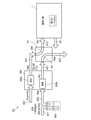
- FIG. 1 is a schematic view showing the configuration of a humidity control system according to the first embodiment of the present invention.
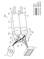
- FIG. 2 is a schematic perspective view showing a configuration example of the suction / detachment device.
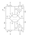
- FIG. 3 is a schematic view showing a configuration example of a moisture permeable device.
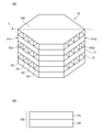
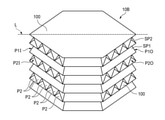
- FIG. 4 is a diagram showing a humidity control element, (a) a schematic perspective view of the humidity control element, and (b) a schematic view of a moisture permeable membrane.
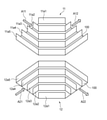
- FIG. 5 is a schematic perspective view of the air passage unit.
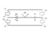
- FIG. 6 is a diagram showing the operating principle of the moisture permeable membrane.
- FIG. 7 is a schematic perspective view showing another example of the humidity control element.
- FIG. 1 is a schematic view showing the configuration of a humidity control system according to the first embodiment of the present invention.
- FIG. 2 is a schematic perspective view showing a configuration example of the suction / detachment device.
- FIG. 3 is a schematic view showing a
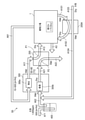
- FIG. 8 is a schematic view showing the configuration of the humidity control system according to the second embodiment of the present invention.
- FIG. 9 is a schematic view showing the configuration of the humidity control system according to the third embodiment of the present invention.
- FIG. 10 is a schematic view showing the configuration of the humidity control system according to the fourth embodiment of the present invention.
- FIG. 11 is a schematic view showing the configuration of the humidity control system according to the fifth embodiment of the present invention.
- FIG. 12 is a schematic view showing the configuration of the humidity control system according to the sixth embodiment of the present invention.
- FIG. 13 is a perspective view showing a schematic configuration of the suction / desorption device according to the seventh embodiment of the present invention.
- FIG. 14 is a schematic perspective view showing a specific configuration example of the suction / desorption device according to the seventh embodiment of the present invention.
- FIG. 15 is a schematic perspective view showing a specific configuration example of the suction / desorption device according to the seventh embodiment of the present invention.
- FIG. 16 is a schematic perspective view showing the configuration of the suction / desorption device according to the eighth embodiment of the present invention.
- FIG. 16 is a schematic perspective view showing the configuration of another humidity control device according to the ninth embodiment of the present invention.
- FIG. 16 is a schematic perspective view showing the humidity control element shown in FIG.
- the humidity control system when carbon dioxide (CO 2 ) is supplied to a plant factory, which is an example of a closed space, the humidity control system, the suction / desorption device, the humidity control device, and the humidity control method are used to control the humidity in the plant factory.
- CO 2 carbon dioxide
- FIG. 1 is a schematic view showing the configuration of the humidity control system S1 according to the first embodiment of the present invention.
- the humidity control system S1 includes an absorption / desorption device 300 and a moisture permeation device 200, and is provided in the vicinity of the plant factory 1.
- the inside of the plant factory 1 is controlled to maintain a constant environment suitable for growing plants. Inside the plant factory 1, as an example, it is necessary to keep the temperature in the range of 22 to 25 ° C., the humidity in the range of 55 to 85% RH, and the CO 2 concentration in the range of higher than 1% (Dry).
- the suction / desorption device 300 has a suction unit 300b and a regeneration unit 300a.
- the adsorption unit 300b adsorbs CO 2 and moisture in the atmosphere A02 to the adsorbent 303 (see FIG. 2) under the first condition
- the regeneration unit 300a adsorbs CO 2 and moisture from the adsorbent 303 under the second condition. It is desorbed to regenerate the adsorbent 303.
- the suction / desorption device 300 has a heater (heating unit) described later as a regeneration device for regenerating the adsorbent 303.
- the first condition is, for example, the adsorbent 303 at room temperature (for example, 0 ° C.
- the second condition is, for example, the adsorbent 303 is about 100 ° C. or higher, and the adsorbent 303 is heated to about 100 by heating with a heater.
- the adsorbent 303 is regenerated at a temperature of ° C or higher.
- the suction / desorption device 300 receives the supply of the regenerated gas A01 from a supply port (supply unit) (not shown ), discharges the CO 2 desorbed from the adsorbent 303, and the gas A11 (first gas) containing water. It is supplied to the first air passage P1 (see FIG. 6) of the moisture permeation device 200.
- the suction / desorption device 300 discharges the gas A21 which is the atmosphere A02 from which CO 2 and moisture have been removed by the adsorbent 303.
- the discharged gas A21 is supplied to the second air passage P2 (see FIG. 6) of the moisture permeation device 200.
- the moisture permeable device 200 includes a moisture permeable membrane 100 (see FIG. 6) that separates the first air passage P1, the second air passage P2, and the first air passage P1 and the second air passage P2.
- the gas A11 and the gas A21 which is a low-humidity gas containing less water than the gas A11, come into contact with each other via the moisture-permeable membrane 100, so that the moisture of the gas A11 moves to the low-humidity gas A21. Then, the water content contained in the gas A11 is reduced (adjusted).
- the outlet of the first air passage P1 of the moisture permeation device 200 leads to the inside of the plant factory 1, and the gas A12 that has passed through the first air passage P1 and has become low in humidity is supplied to the inside of the plant factory 1.
- the gas A3, which is the air inside the plant factory 1 is appropriately discharged from the plant factory 1 according to the amount of gas A12 supplied from the moisture permeation device 200 and the like. Further, the gas A4 containing the gas A3 and the high humidity gas A22 discharged from the moisture permeable device 200 is supplied to the adsorbent 303 (adsorption portion 300b) of the suction / desorption device 300 together with the atmosphere A02. This makes it possible to improve the adsorption performance of the adsorbent 303, for example, when an adsorbent having an improved adsorptive power under humidified conditions is used, such as some amine polymer-based adsorbents.
- FIG. 2 is a schematic perspective view showing a configuration example of the suction / desorption device 300 shown in FIG.
- the suction / desorption device 300 includes an adsorbent 303, a rotor 302 filled with the adsorbent 303, a heater H (heating unit), and two fans F2 and F3.
- the adsorbent 303 is a material capable of repeatedly adsorbing and desorbing CO 2 only by changing the temperature.
- the adsorbent 303 can be used by being filled in a cylindrical body or being held by a filter.
- the adsorbent 303 adsorbs CO 2 in the air by coming into contact with the supplied air (atmosphere) at room temperature (first temperature, for example, 0 ° C to 40 ° C).
- first temperature for example, 0 ° C to 40 ° C.
- second temperature for example, about 100 ° C.
- the adsorbent 303 adsorbs CO 2 in the supplied air at atmospheric pressure (first atmospheric pressure), and the inside of the container containing the adsorbent 303 is depressurized (second atmospheric pressure, for example, 10000 Pa). in, CO 2 and water was desorbed, it is reproduced can adsorb again CO 2 and moisture.
- second atmospheric pressure for example, 10000 Pa
- the adsorbent 303 examples include metal carbonates such as potassium carbonate and calcium carbonate, liquid amines such as monoamine aqueous solutions, those in which a porous body is filled with an amine liquid, those in which the surface of the porous body is modified with an amine monomer, and an amine polymer. It is preferable to use a solid amine.
- an inorganic porous body such as activated carbon, zeolite or silica, an ion exchange resin such as a quaternary amine-containing ion exchange resin, a metal-organic framework (MOF: Metal Organic Frameworks) alone, or an amine-modified MOF can be used. Can be used.
- the rotor 302 has a hollow cylindrical shape, is filled with an adsorbent 303, and is rotationally driven around a central axis at a constant speed by a motor or the like (not shown).
- adsorbent 303 filled in the rotor 302 the region that adsorbs CO 2 and water functions as the adsorption unit 300b, and the region that is heated to desorb CO 2 and water functions as the regeneration unit 300a.
- the fan F3 is provided below one side of the rotor 302.
- the fan F3 sucks the CO 2- containing gas A02 (atmosphere A02) from the outside and supplies it to the adsorbent 303.
- the CO 2- containing gas A02 is adsorbed and removed from CO 2 and water while in contact with the adsorbent 303 filled in the rotating rotor 302, and is used as the CO 2 removing gas A21 (gas A21) to the outside of the suction / desorption device 300. It is discharged.
- the heater H is an electric heater that is fixedly arranged on the other surface side of the rotor 302 and heats the regenerated gas A01 (atmosphere A01) for regenerating the adsorbent 303.
- the regenerated gas A01 heated by the heater H becomes hot, and is supplied to the adsorbent 303 by operating the fan F2.
- the heated regenerated gas A01 is supplied to the adsorbent 303, and the adsorbent 303 adsorbing CO 2 and water is heated to a predetermined temperature.
- the fan F2 is provided above the one side of the rotor 302.
- the high temperature regenerated gas A01 is supplied to the adsorbent 303 from the other surface side of the rotor 302.
- CO 2 and water adsorbed on the adsorbent 303 are desorbed to become CO 2 concentrated gas A11 (gas A11), and the adsorbent 303 is regenerated.
- the CO 2 concentrated gas A11 is discharged to the outside of the suction / desorption device 300 from one side of the rotor 302.
- the region to which the heated regenerated gas A01 is supplied functions as the regenerating portion 300a, and the other regions function as the adsorbing portion 300b.
- the region that was functioning as the suction unit 300b shifts to the region that functions as the regeneration unit 300a due to the rotation of the rotor 302, and the region that functions as the regeneration unit 300a is the region that functions as the suction unit 300b. Move to the area that functions as. These transitions are continuous.
- adsorption and desorption apparatus 300 shown in FIG. 2 CO 2 and water recovered from CO 2 containing gas A02, the CO 2 enriched gas A11 can be supplied to the moisture permeable device 200.
- FIG. 3 is a schematic view showing a configuration example of the moisture permeable device 200.
- the solid arrow indicates the flow of the gas A11 and A12 passing through the first air passage P1
- the broken line arrow indicates the flow of the gas A21 and A22 passing through the second air passage P2.
- the moisture permeation device 200 includes a humidity control element 10, a case 201, and fans 212 and 213.
- the humidity control element 10 will be described later.
- Case 201 accommodates the humidity control element 10.
- the case 201 is provided with partition walls 202, 203, 204, 203 inside.
- the partition walls 202 and 203 extend in the horizontal direction and vertically partition the internal space of the case 201.
- the partition wall 204 extends in the vertical direction and horizontally partitions the upper side of the internal space of the case 201.
- the partition wall 205 extends in the vertical direction and horizontally partitions the lower side of the internal space of the case 201.
- the humidity control element 10 is connected to the partition walls 202 to 205 and is fixed to the center of the internal space of the case 201.
- the internal space of the case 201 is divided into two spaces, the first space 200a and the second space 200b, on the upper side, and the third space 200c and the fourth space 200d on the lower side.
- Connection ports 208 to 211 are provided outside the case 201.
- the connection ports 208 and 210 are attached to the openings (not shown) on the left side wall of the case 201, respectively.
- the gas A21 is supplied to the first space 200a via the connection port 208.
- the gas A21 that has passed through the humidity control element 10 via the fan 213 and the connection port 210 is discharged to the outside from the third space 200c as the gas A22 having high humidity.
- the gas A11 is supplied to the second space 200b via the connection port 209.
- the gas A11 that has passed through the humidity control element 10 is supplied from the fourth space 200d into the plant factory 1 as the low humidity gas A12 via the fan 212 and the connection port 211.
- the fan 212 is arranged in the connection port 211 on the right side wall of the case 201 in the fourth small space 200d, and supplies the gas A11 to the first air passage P1 of the humidity control element 10 or the gas A12 from the first air passage P1. Promote the emission of.
- the fan 213 is arranged in the connection port 210 on the left side wall of the case 201 in the second space 200c, and supplies the gas A21 to the second air passage P2 of the humidity control element 10 or the gas A22 from the second air passage P2. Promote emissions.
- the operation of the fans 212 and 213 is controlled by a control unit (not shown).
- the operation of the moisture permeation device 200 will be described.
- Fans 212 and 213 are driven by the control unit.
- the gas A11 containing CO 2 and water is taken into the second space 200b in the case 201 from the suction / desorption device 300 via the connection port 209.
- the taken-in gas A11 is supplied from the inlet P1I to the first air passage P1 of the humidity control element 10.
- the gas A11 passing through the first air passage P1 is totally heat exchanged (sensible heat and latent heat) with the low humidity gas A21 passing through the second air passage P2 via the moisture permeable film 100, and the fourth space from the outlet P1O. It reaches 200d and is supplied into the plant factory 1 via the fan 212 and the connection port 211.
- the low-humidity gas A21 discharged from the suction / desorption device 300 is taken into the first space 200a in the case 201 via the connection port 208.
- the taken-in gas A21 is supplied from the inlet P2I to the second air passage P2 of the humidity control element 10.
- the gas A21 passing through the second air passage P2 is totally heat exchanged with the gas A11 passing through the first air passage P1 via the moisture permeable membrane 100, and reaches the third space 200e from the outlet P2O.
- the gas A21 containing water and heat from the gas A11 is discharged to the outside of the moisture permeable device 200 as the gas A22 via the fan 213 and the connection port 210.
- FIG. 3 The details of the humidity control element 10 shown in FIG. 3 will be described with reference to FIGS. 4 to 6.
- 4A and 4B are views showing the humidity control element 10,
- FIG. 4A is a schematic perspective view of the humidity control element
- FIG. 4B is a schematic view of the moisture permeable membrane.
- FIG. 5 is a schematic perspective view of the air passage unit
- FIG. 6 is a diagram showing the operating principle of the moisture permeable membrane.
- the humidity control element 10 is formed by alternately stacking air passage units 11 and 12, and includes a first air passage P1, a second air passage P2, a moisture permeable membrane 100, and the like. To prepare for.
- the first air passage P1 is discharged from the adsorption-desorption apparatus 300, a high CO 2 concentration, high humidity, and is passed through a high-temperature gas A11.
- the second air passage P2 passes through the low-humidity gas A21 discharged from the suction / desorption device 300.
- the moisture permeable membrane 100 may have at least moisture permeability, gas barrier property and thermal conductivity, and its material and composition are not particularly limited.
- the moisture permeable film 100 includes, for example, a porous base paper (Japanese paper, kraft paper, etc.) mainly composed of cellulose fibers in which a moisture absorbing material such as calcium chloride (CaCl 2 ) is dispersed (kneaded), or cellophane.
- a fiber layer containing water-insoluble fibers such as chitin and fibroin in which a hydrophilic material such as aggregated polyethylene glycol and polyvinyl alcohol is dispersed can be used.
- the moisture permeable membrane 100 includes a support 120 and a composite material 110.
- the support 120 contains a porous material such as a polymer or hollow fiber.
- the composite material 110 may be applied onto the support 120.
- the composite material 110 contains a graphene oxide compound and polyvinyl alcohol.
- the graphene oxide compound and polyvinyl alcohol may be crosslinked.
- the graphene oxide compound may be present in an amount of about 0.1% by weight to about 10% by weight based on the weight of polyvinyl alcohol.
- the graphene oxide compound may be graphene oxide, reduced graphene oxide, functionalized graphene oxide, or functionalized and reduced graphene oxide.
- the air passage unit 11 has a moisture permeable membrane 100 having a hexagonal shape in a plan view, and ribs 11a1 to 11a5 erected on the surface of the moisture permeable membrane 100.
- the rib 11a1 has a linear shape along one side of the hexagonal shape.
- the ribs 11a2 to 11a5 each have a straight portion having the same shape as the rib 11a1 and an extending portion extending from both ends of the straight portion.
- the ribs 11a5 are provided along the edge of the moisture permeable membrane 100, and the ribs 11a4 to 11a1 are arranged at equal intervals so that the straight portions are parallel to each other.
- the air passage unit 12 has a moisture permeable membrane 100 having a hexagonal shape in a plan view, and ribs 12a1 to 12a5 erected on the surface of the moisture permeable membrane 100.
- the rib 12a1 has a linear shape along one side of the hexagonal shape.
- the ribs 12a2 to 12a5 each have a straight portion having the same shape as the rib 12a1 and an extending portion extending from both ends of the straight portion.
- the ribs 12a5 are provided along the edge of the moisture permeable membrane 100, and the ribs 12a1 to 12a4 are arranged at equal intervals so that the straight portions are parallel to each other.
- the ribs 11a1 to 11a5 and the ribs 12a1 to 12a5 resins such as polyethylene and polypropylene, metals such as aluminum, glass, ceramics, fiber materials, wood, paper materials and the like can be used. In particular, if a material having good hygroscopicity is used, the moisture permeability performance (latent heat exchange efficiency) of the humidity control element is improved.
- the air passage units 11 and 12 are laminated so that the straight portions of the ribs 11a1 to 11a5 and the ribs 12a1 to 12a5 are parallel to each other.
- the ribs 11a1 to 11a5 and the moisture permeable membranes 100 arranged above and below the ribs 11a1 to 11a5 form the first air passage P1 and form the ribs 12a1 to 12a5.
- the moisture permeable membranes 100 arranged above and below the ribs 12a1 to 12a5 form the second air passage P2.
- a moisture permeable membrane 100 is fixed above the air passage unit 12 in the uppermost layer.
- the inlet P1I of the first air passage P1 leads to the regeneration unit 300a of the suction / desorption device 300, and the outlet P1O leads to the inside of the plant factory 1 (see FIGS. 1 and 3).
- the inlet P2I of the second air passage P2 leads to the suction portion 300b of the suction / desorption device 300, and the outlet P2O leads to the outside of the plant factory 1 (see FIGS. 1 and 3).
- the inlet P1I and the outlet P1O of the first air passage P1 connect the moisture permeable membrane 100 to two vertices facing each other across the hexagonal outer center of the moisture permeable membrane 100 (in the left-right direction in FIG. 4A).
- the inlet P2I and the outlet P2O of the second air passage P2 are arranged on the other side of the other region.
- the number of laminated air passage units 11 and 12 in the humidity control element 10, and the height, width (interval between adjacent ribs) and number of the ribs 11a1 to 11a5 and the ribs 12a1 to 12a5 are appropriately determined according to the specifications. It is set and is not limited to that shown in FIGS. 4 (a) and 5.
- the moisture permeable membrane 100 has a gas barrier property and separates the first air passage P1 and the second air passage P2.
- the moisture permeable membrane 100 has moisture permeability, and has a water vapor concentration between the gas A11 (first gas) passing through the first air passage P1 and the gas A21 (second gas) passing through the second air passage P2. Water vapor is permeated using the gradient. Since the gas A11 flowing into the first air passage P1 has a higher water vapor concentration than the gas A21 flowing into the second air passage P2, the water vapor (humidity) contained in the gas A11 permeates the moisture permeable membrane 100 and the gas A21. Move to.
- the gas A22 containing an increased amount of water vapor as it passes through the second air passage P2 is discharged to the outside from the second air passage P2.
- the gas A12 in which the amount of water vapor contained decreases as it passes through the first air passage P1 is supplied from the first air passage P1 into the plant factory 1.
- the moisture permeable membrane 100 has thermal conductivity, and the heat of the gas A11 passing through the first air passage P1 is transferred to the gas A21 passing through the second air passage P2. In this way, the moisture permeable membrane 100 performs sensible heat exchange and latent heat exchange between the gas A11 and the gas A21.
- the moisture permeable membrane 100 does not allow CO 2 to permeate due to its gas barrier property.
- the sensible heat exchange efficiency and the latent heat exchange efficiency of the moisture permeable membrane 100 are affected by the thickness (thinner is better), and the temperature difference and humidity difference through the membrane (the larger the difference, the higher the efficiency). Further, the sensible heat exchange efficiency of the moisture permeable film 100 is affected by the thermal conductivity of the material, and the latent heat exchange efficiency of the moisture permeable film 100 is also affected by the moisture permeability (water vapor permeability) and water absorption of the material. The material and thickness of the moisture permeable membrane 100 are determined in consideration of these influences.
- the high-temperature gas A11 containing CO 2 and moisture discharged from the suction / desorption device 300 is supplied to the plant factory 1 as the gas A12 through the first air passage P1 and is a gas.
- A21 passes through the second air passage P2 and is discharged to the outside of the building as gas A22.
- the moisture and heat contained in the gas A11 can be released to the outside of the plant factory 1.
- the humidity control system S1 when the suction / desorption device 300 supplies CO 2 recovered from the atmosphere, the humidity and temperature are adjusted by the moisture permeation device 200, so that the humidity in the plant factory 1 is stable. Can be achieved. Further, since the humidity control element 10 can be used to dehumidify without using a dehumidifier, the energy cost for humidity adjustment can be reduced.
- the number of layers of the air passage units 11 and 12 is appropriately set according to the specifications of the humidity control element 10, for example, 200 steps, but by increasing the number of layers, the moisture permeable membrane 100 and the gas A11 and the gas A21 are combined.
- the contact area can be increased to improve the amount of dehumidification.
- the ribs 11a1 to 11a5 and the ribs 12a1 to 12a5 each have a straight line portion parallel to each other, the gas A11 and the gas A21 passing through the straight line portion (parallel portion) come into contact with each other via the moisture permeable membrane 100. Since the time required for dehumidification becomes longer, the amount of dehumidification can be improved.
- the above-mentioned humidity control element 10 has ribs 11a1 to 11a5 and ribs 12a1 to 12a5 erected on the surface of the moisture permeable membrane 100, but instead of the ribs, a wave shape (wave shape) between adjacent moisture permeable membranes 100.
- a corrugated spacer may be provided.
- the spacer SP1 and the moisture permeable membranes 100 arranged above and below the spacer SP1 form the first air passage P1
- the spacer SP2 and the spacer SP2 are arranged above and below.
- the moisture permeable membrane 100 constitutes the second air passage P2.
- the inlet P1I and the outlet P1O of the first air passage P1 lead to the inside of the plant factory, and the inlet P2I and the outlet P2O of the second air passage P2 lead to the outside of the plant factory.
- the inlet P1I and the outlet P1O of the first air passage P1 connect the moisture permeable membrane 100 to two vertices facing each other across the hexagonal outer center of the moisture permeable membrane 100 (a straight line L extending in the left-right direction in FIG. 7). ) Is divided into two, and it is placed on one side of one area. Further, the inlet P2I and the outlet P2O of the second air passage P2 are arranged on the other side of the other region.
- the inlet P1I and the outlet P1O of the first air passage P1 are arranged in one region, and the inlet P2I and the outlet P2O of the second air passage P2 are arranged in the other region across the straight line L, whereby the plant is arranged.
- the number of layers of the moisture permeable membrane 100 and the spacers SP1 and SP2 in the humidity control element 10B, and the height, width (interval between adjacent waves) and number of waves in the spacers SP1 and SP2 are appropriately set according to the specifications. It is not limited to the one shown in FIG. 7.
- FIG. 8 is a schematic view showing the configuration of the humidity control system S2 according to the second embodiment of the present invention.
- the same or equivalent members / parts as those shown in FIGS. 1 to 7 may be designated by the same reference numerals, and duplicate description may be omitted.
- the humidity control system S2 has a point that the high humidity gas A22 discharged from the moisture permeation device 200 is not supplied to the suction / desorption device 300 and a point that the humidification device 400 is provided. different.
- the supply amount of the regenerated gas A01 to the adsorbent 303 (regeneration unit 300a) of the suction / desorption device 300 is reduced to, for example, 10 m 3 / hr, so that the inside of the plant factory 1 is passed through the moisture permeation device 200.
- the supply of high CO 2 gas is suppressed.
- the temperature and humidity of the plant factory 1 are controlled, and it is not preferable to introduce the temperature and humidity.
- the supply amount of high CO 2 gas is reduced to control the indoor temperature of the plant factory 1. There is no need to exhaust air (internal air). Therefore, it becomes easy to manage the indoor air while appropriately supplying CO 2.
- the humidifying device 400 humidifies the atmosphere A71 having a CO 2 concentration of about 400 ppm to about 500 m 3 / hr, and supplies it as a highly humid gas A02 to the adsorption unit 300b of the suction / desorption device 300.
- the humidified gas A02 By supplying the humidified gas A02, the adsorption performance of the adsorbent 303 can be improved.
- the piping for supplying the gas A22 discharged from the moisture permeation device 200 to the suction / desorption device 300 becomes unnecessary, and the system configuration is simplified. Can be changed.
- the humidifying device 400 is not essential.
- FIG. 9 is a schematic view showing the configuration of the humidity control system S3 according to the third embodiment of the present invention.
- the same or equivalent members / parts as those shown in FIGS. 1 to 8 may be designated by the same reference numerals, and duplicate description may be omitted.
- the humidity control system S3 has an atmosphere A81 (external) in the second air passage P2 of the moisture permeation device 200 instead of the gas A21 discharged from the suction / desorption device 300.
- the point of supplying air is different.
- the humidity control system S3 in addition to the effect of the humidity control system S2, even when the humidity of the gas A21 discharged from the suction / desorption device 300 is high, the gas in the moisture permeation device 200 utilizes the atmosphere A81. By adjusting the humidity of A11, the high CO 2 concentration gas A11 can be dehumidified.
- FIG. 10 is a schematic view showing the configuration of the humidity control system S4 according to the fourth embodiment of the present invention.
- the same or equivalent members / parts as those shown in FIGS. 1 to 9 may be designated by the same reference numerals, and duplicate description may be omitted.
- the humidity control system S4 uses the indoor air A91 (internal air) in the plant factory 1 instead of the atmosphere A01 as the adsorbent 303 (regeneration) of the suction / desorption device 300.
- the point of supplying to the unit 300a) is different.
- the humidity control system S4 in addition to the effect of the humidity control system S2, by circulating and reusing the controlled indoor air in the plant factory 1 as the regenerated gas, it is not necessary to reduce the air volume of the regenerated gas, for example, 10 It has the effect of being able to supply regenerated gas as appropriate according to the required amount of CO 2 and the like, such as ⁇ 500 m 3 / hr.
- FIG. 11 is a schematic view showing the configuration of the humidity control system S5 according to the fifth embodiment of the present invention.
- the same or equivalent members / parts as those shown in FIGS. 1 to 10 may be designated by the same reference numerals, and duplicate description may be omitted.
- the humidity control system S5 is different from the humidity control system S4 of the fourth embodiment in that it includes a moisture permeation device 200A.
- the moisture permeation device 200A has a third air passage through which the gas A101 (internal air), which is the air in the plant factory 1, and a fourth air passage through the atmosphere A103 (low humidity gas) containing less water than the gas A101. And prepare. Further, the moisture permeable device 200A has a moisture permeable film that separates the third air passage and the fourth air passage and allows moisture to permeate between the gas A101 and the atmosphere A103.
- the gas A101 is transferred to the low humidity atmosphere A103 through the moisture permeable membrane to become the low humidity gas A102, and is returned to the plant factory 1. Further, the low-humidity atmosphere A103 obtains the moisture of the gas A101 through the moisture-permeable membrane to become a high-humidity gas A104, and is supplied to the adsorbent 303 (adsorption portion 300b) of the suction / desorption device 300.
- the adsorbent 303 can exhibit high adsorption performance without humidifying the atmosphere A71 by the humidifying device 400.
- FIG. 12 is a schematic view showing the configuration of the humidity control system S6 according to the sixth embodiment of the present invention.
- the same or equivalent members / parts as those shown in FIGS. 1 to 11 may be designated by the same reference numerals, and duplicate description may be omitted.
- the humidity control system S6 is provided with a steam supply unit 410 as compared with the humidity control system S3 of the third embodiment, and sucks steam or high humidity air A03 supplied from the steam supply unit 410 instead of the atmosphere A01. The difference is that they are supplied to the regenerating unit 300a of the attachment / detachment device 300. Further, in the humidity control system S3, the high humidity gas A02 humidified by the humidifying device 400 was supplied to the adsorption unit 300b of the suction / desorption device 300, whereas in the humidity control system S6, the low humidity atmosphere A02 was supplied to the adsorption unit 300b. Is supplied to.
- the steam supply unit 410 is a device that humidifies air by a boiler or a spray, and supplies steam or high-humidity air having a humidity of, for example, 80% RH or more.
- the steam supply unit 410 supplies the steam A03 to the regeneration unit 300a, which enables high-efficiency heating by latent heat heating or condensation heat transfer.
- the steam supply unit 410 and the regeneration unit 300a function as a regeneration device that regenerates at least a part of the adsorbent that has adsorbed carbon dioxide and water. Therefore, it is not necessary to provide a heater in the suction / desorption device 300.
- the steam supply unit 410 supplies steam or high humidity air A03 to the regeneration unit 300a to suppress water desorption from the adsorbent 303, the adsorbent 303 releases CO 2 and moisture during regeneration. The energy consumed at that time can be reduced.
- suction / desorption device 300A The details of the suction / desorption device 300A will be described with reference to FIGS. 13 to 15.
- the suction / desorption device 300A can be used in the humidity control systems S1 to S6 according to the first to sixth embodiments instead of the rotor type suction / desorption device 300 shown in FIG.
- FIG. 13 is a perspective view showing a schematic configuration of the suction / desorption device 300A.
- the suction / desorption device 300A has an adsorbent 301 and four columns C1 to C4, each of which is filled with the adsorbent 301.
- the adsorbent 301 is the same material as the adsorbent 303, and is filled in each column C1 to C4.
- the columns C1 to C4 have a hollow cylindrical shape, and the columns C1 to C4 are collectively arranged so that their side surfaces are close to each other.
- the CO 2- containing gas A02 (atmosphere A02) is supplied to the three columns C1, C2, and C4, and one column C3 is heated.
- the CO 2- containing gas A02 supplied to the three columns C1, C2, and C4 is adsorbed and removed by CO 2 and water while in contact with the filled adsorbent 301, and the CO 2 removing gas A21 (gas A21). It is discharged to the outside of the suction / desorption device 300A.
- the adsorbent 301 inside has already sufficiently adsorbed CO 2 and is in a broken state, and when it is heated, CO 2 and water are desorbed. That is, when the column C3 is heated, the CO 2 concentrated gas A11 (gas A11) is discharged, and the adsorbent 301 is regenerated.
- the adsorbent 301 filled in the three columns C1, C2, and C4 functions as the adsorbent unit 300b
- the adsorbent 301 filled in the column C3 functions as the regeneration unit 300a.
- the suction / desorption device 300A shown in FIG. 13 can continuously function the adsorbent 301 filled in each of the columns C1 to C4 as the adsorbing unit 300b and the regenerating unit 300a.
- the number of columns is an example and does not have to be four in total, and the column to be heated may be a part of the whole, and is not limited to one.
- FIG. 14 is a schematic perspective view showing a specific configuration example of the suction / desorption device 300A.
- the suction / desorption device 300A shown in FIG. 14A has a shaft 304 for fixing the columns C1 to C4 at the center of the assembled columns C1 to C4, and is located near the column C3 on one end side of the columns C1 to C4.
- the heater H is arranged.
- the heater H heats the regenerated gas A01 and supplies it to the adsorbent 301 filled in the column C3.
- the heated regenerated gas A01 is supplied to the adsorbent 301 to heat the adsorbent 301 that has adsorbed CO 2 and moisture.
- CO 2 and water desorbed from the adsorbent 301 are discharged from the column C3 as CO 2 concentrated gas A11.
- the shaft 304 When the shaft 304 is rotated by a motor or the like (not shown), the columns C1 to C4 fixed to the outer periphery of the shaft 304 rotate around the shaft 304, and the columns C3 filled with the regenerated adsorbent 301 in addition to the columns C4 and C1.
- the CO 2- containing gas A02 is supplied to the vehicle.
- the CO 2 removing gas A21 is discharged from the columns C3, C4, and C1.
- a column C2 filled with an adsorbent 301 that has become a breakthrough state by adsorbing CO 2 is arranged at a position close to the heater H, and when the heated regenerated gas A01 is supplied to the adsorbent 301, CO 2 and water are desorbed, and the adsorbent 301 is regenerated.
- the arrangement of the heater H is different from that in FIG. 14A.
- the heater H is arranged on the side of the column C3.
- the heater H directly heats the column C3 to heat the adsorbent 301 filled in the column C3 and adsorbing CO 2 and moisture. CO 2 and water desorbed from the adsorbent 301 heated to a predetermined temperature are discharged from the column C3 as CO 2 concentrated gas A11.
- the shaft 304 When the shaft 304 is rotated by a motor or the like (not shown), the columns C1 to C4 fixed to the outer periphery of the shaft 304 rotate around the shaft 304, and the column is filled with the regenerated adsorbent 301 in addition to the columns C4 and C1.
- the CO 2- containing gas A02 is supplied to C3.
- the CO 2 removing gas A21 is discharged from the columns C3, C4, and C1.
- a column C2 filled with an adsorbent 301 that has been in a broken state by adsorbing CO 2 is arranged at a position close to the heater H.
- the suction / desorption device 300A shown in FIG. 14C is different from the suction / desorption device 300A in that it does not have a shaft 304, the columns C1 to C4 are fixedly arranged, and the heater H rotates.
- the heater H is divided into four quarters around the central axis (see axis 304 in FIG. 14A) in the direction indicated by the arrow Db so as to be located near each of the columns C1 to C4 on one end side of the columns C1 to C4. Move one lap at a time.
- the heater H heats the regenerated gas A01 and supplies it to the adsorbent 301 filled in the column C3.
- the heated regenerated gas A01 is supplied to the adsorbent 301 to heat the adsorbent 301 that has adsorbed CO 2 and moisture. CO 2 and water desorbed from the adsorbent 301 are discharged from the column C3 as CO 2 concentrated gas A11.
- the heater H moves in the direction of the arrow Db by a quarter rotation, the heater H is arranged at a position close to the column C2.
- the heated regenerated gas A01 is supplied to the column C2 from the heater H.
- the adsorbent 301 that has adsorbed CO 2 and is in a fractured state, CO 2 and water are desorbed, and the adsorbent 301 is regenerated.
- the CO 2- containing gas A02 is supplied to the column C3 filled with the regenerated adsorbent 301 in addition to the columns C4 and C1 by switching the flow path or the like.
- the CO 2 removing gas A21 is discharged from the columns C3, C4, and C1.
- the arrangement of the heater H is different from that in FIG. 14 (c).
- the heater H moves one quarter around the central axis (see axis 304 in FIG. 14A) in the direction indicated by the arrow Db so as to be located on the side of each column C1 to C4.
- the heater H directly heats the column C3 to heat the adsorbent 301 filled in the column C3 and adsorbing CO 2 and water. CO 2 and water desorbed from the adsorbent 301 heated to a predetermined temperature are discharged from the column C3 as CO 2 concentrated gas A11.
- the heater H moves in the direction of the arrow Dd by a quarter rotation, the heater H is arranged at a position close to the column C2 filled with the adsorbent 301 which has adsorbed CO 2 and is in a fractured state.
- the heater H directly heats the column C2 and the adsorbent 301 is heated to a predetermined temperature, CO 2 and moisture are desorbed from the adsorbent 301 filled in the column C2, and the adsorbent 301 is regenerated. It becomes.
- the CO 2- containing gas A02 is supplied to the column C3 filled with the regenerated adsorbent 301 in addition to the columns C4 and C1 by switching the flow path or the like.
- the CO 2 removing gas A21 is discharged from the columns C3, C4, and C1.
- FIG. 15 is a schematic perspective view showing a specific configuration example of the suction / desorption device 300A.
- the suction / desorption device 300A shown in FIG. 15 further includes a fan F1 and a heater H in the suction / desorption device 300A shown in FIG. 13, and a connection portion 305 is attached to one end of each column C1 to C4.
- the fan F1 supplies air (CO 2 containing gas A02) to the columns C1 to C4, and the heater H supplies heated air (regenerated gas A01) to the columns C1 to C4.
- connection portion 305 connects the pipes PF1 to PF4 from the fan F1 to the columns C1 to C4 and the pipes PH1 to PH4 from the heater H to the columns C1 to C4 to the columns C1 to C4, respectively.
- the suction / desorption device 300A supplies and stops the supply and supply of air and heated air to the columns C1 to C4 by switching a valve (not shown).
- the adsorbent 301 filled in any of the columns C1 to C4 to which air is supplied functions as an adsorbent 300b, and the adsorbent 301 filled in any of the columns C1 to C4 to which heated air is supplied is a regeneration unit. Functions as 300a. By switching the valve, which column C1 to C4 functions as the suction unit 300b or the regeneration unit 300a is switched.
- a decompression device for depressurizing the inside of the column C3 may be provided as a regeneration device, and the gas A11 may be discharged by depressurizing the inside of the column C3.
- the first condition for the adsorbent 301 (adsorption portion 300b) to adsorb CO 2 and water in the CO 2 containing gas A02 is, for example, the atmospheric pressure in each column C1 to C4 accommodating the adsorbent 301. Atmospheric pressure.
- the second condition for desorbing CO 2 and water from the adsorbent 301 (regenerating section 300a) to regenerate the adsorbent 301 is that the air pressure in the column C3 is, for example, 10000 Pa, and the column C3 is operated by a decompression device. By lowering the air pressure inside to 10000 Pa, the adsorbent 301 is regenerated.
- the regenerated gas A01 and A91 are not indispensable in the humidity control systems S1 to S5, and the gas A11 can be discharged only by the depressurization or by the combined use of the depressurization and heating.
- FIG. 16 is a perspective view showing a schematic configuration of the suction / desorption device 300B.
- the suction / desorption device 300B has a chamber 310, a filter 320, a supply port 330, and discharge ports 340 and 350.
- the chamber 310 has a box shape and has an internal space capable of accommodating gas.
- the filter 320 holds the adsorbent 303 on the entire surface and is fixed to the internal space of the chamber 310.
- the filter 320 is heated by a heater (not shown).
- the supply port 330 is attached to an opening on one side wall of the chamber 310, and a pipe or the like leading to the outside is connected to the supply port 330.
- the CO 2- containing gas A02 is supplied to the internal space of the chamber 310 through the supply port 330.
- the discharge port 340 is attached to the opening of the other side wall of the chamber 310 facing the side wall to which the supply port 330 is attached, and is connected to the second air passage P2 of the moisture permeable device 200 or a pipe leading to the outside.
- the CO 2 removing gas A21 is discharged to the moisture permeable device 200 or the outside through the discharge port 340.
- the discharge port 350 is attached to the opening of the side wall connecting one side wall and the other side wall in the chamber 310, and is connected to a pipe or the like leading to the first air passage P1 of the moisture permeation device 200.
- the CO 2- containing gas A02 is supplied to the internal space of the chamber 310 through the supply port 330 at room temperature (heater off state).
- the chamber 310 CO 2 and water are adsorbed on the adsorbent 303 of the filter 320.
- CO 2 containing gas A02 CO 2 stripping gas A21 to CO 2 and moisture are removed from through the discharge port 340 is discharged to moisture permeation device 200 or external. That is, at room temperature, the adsorbent 303 held by the filter 320 functions as the adsorbent 300b.
- the suction / desorption device 300B when the filter 320 is heated and the adsorbent 303 reaches a predetermined temperature (heater on state), CO 2 and water are desorbed from the adsorbent 303 of the filter 320. The desorbed CO 2 and water are discharged as CO 2 concentrated gas A11 through the discharge port 350, and the adsorbent 303 is regenerated. That is, at a predetermined temperature, the adsorbent 303 held by the filter 320 functions as the regeneration unit 300a.
- the entire adsorbent 303 held by the filter 320 adsorbs CO 2 and moisture at room temperature, and when the temperature is brought to a predetermined temperature by heating, the adsorbent 303 is desorbed from CO 2 and moisture. Reproduce.
- the suction / desorption device 300B causes the adsorbent 303 to function as the regeneration unit 300a or the adsorption unit 300b by turning the heater on and off.
- adsorption and desorption apparatus 300B shown in FIG. 16 the CO 2 and water recovered from CO 2 containing gas A02, the CO 2 enriched gas A11 can be supplied to the moisture permeable device 200.
- the suction / desorption device 300B heats the adsorbent 303 with a heater to discharge the CO 2 concentrated gas A11, but instead of the heater, a decompression device (not shown) is provided as a regeneration device.
- CO 2 concentrated gas A11 may be discharged by reducing the pressure in the chamber 310.
- the first condition for the adsorbent 303 (adsorption portion 300b) to adsorb CO 2 and water in the CO 2- containing gas A02 is the air pressure in the chamber 310 containing the adsorbent 303 held in the filter 320.
- it is atmospheric pressure.
- the second condition for desorbing CO 2 and water from the adsorbent 303 to regenerate the adsorbent 303 is that the air pressure in the chamber 310 is, for example, 10000 Pa, and the air pressure in the chamber 310 is lowered by a decompression device. By setting the value to 10000 Pa, the adsorbent 303 is regenerated.
- the regenerated gas A01 and A91 are not indispensable in the humidity control systems S1 to S5, and the gas A11 can be discharged only by the depressurization or by the combined use of the depressurization and heating.
- Membrane dryer 500 instead of the moisture permeable device 200 described above, the membrane dryer 500 shown in FIG. 17 may be used.
- FIG. 17 is a schematic view of the membrane dryer 500.
- FIG. 17 is a cross-sectional view of a part of the membrane dryer 500 in a side view.
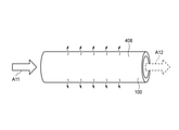
- the membrane dryer 500 includes a hollow cylindrical case 402 having both ends open, a plurality of humidity control elements 408 arranged in the case 402, and end cases 404 and 406 that cover both ends of the case 402, respectively. ..
- the membrane dryer 500 includes a holding member 510 that closes both ends of the case 402 and holds both ends of the humidity control element 408 in the end cases 404 and 406.
- the holding member 510 closes between the plurality of humidity control elements 408 and the end cases 404, 406.
- the case 402 is provided with two openings 402a and 402b that allow the inside and outside of the case 402 to communicate with each other.
- the end cases 404 and 406 have openings 404a and 406a, respectively.
- FIG. 18 is a schematic perspective view of the humidity control element 408.
- the humidity control element 408 is a hollow fiber membrane, and has a tubular portion in which a flat moisture permeable film 100 is formed in a hollow tubular shape.
- the hollow portion inside the cylinder is the first air passage through which the internal air passes
- the space outside the cylinder that is, the space in contact with the outer peripheral surface is the second air passage through which the outside air passes. ..
- the humidity control element 408 permeates water vapor using a water vapor concentration gradient between the gas A11 (internal air) passing through the inside of the humidity control element 408 and the external air passing through the outer peripheral surface of the humidity control element 408. Let me. When the gas A11 has a higher water vapor concentration than the external air, the water vapor contained in the gas A11 permeates the moisture permeable membrane 100 and moves to the external air passing through the outer peripheral surface of the humidity control element 408. Further, the humidity control element 408 has thermal conductivity, and the heat of the gas A11 is transferred to the outside air via the humidity control element 408.
- the difference in water vapor concentration between the internal air and the external air may be provided by pressurizing the internal air to increase the water vapor concentration or depressurizing the external air to decrease the water vapor concentration.
- the gas A12 in which the amount of water vapor contained and the heat decreased as it passed through the inside of the humidity control element 408 is supplied to the plant factory 1.
- Either the inside or the outside of the humidity control element 408 may be the first air passage or the second air passage.
- the gas A11 flowing in from the opening 404a passes through the inside of the plurality of humidity control elements 408.
- Gas A21 is supplied from the opening 402a to the outer peripheral surface of the humidity control element 408 in the case 402, and total heat exchange with the gas A11 is performed.
- the gas A12 having a reduced amount of water vapor and heat contained is discharged from the opening 406a and returned to the plant factory 1.
- the gas A22 which has received the transfer of water vapor and heat from the gas A11 on the outer peripheral surface of the humidity control element 408, is discharged from the opening 402b to the external space outside the plant factory 1, or the adsorbent 303 of the suction / desorption device 300. Is supplied to.
- the present invention is not limited to the above-described embodiment, and can be appropriately modified, improved, or the like.
- a plurality of embodiments may be combined and implemented among the above-described embodiments.
- the material, shape, size, numerical value, form, number, arrangement location, etc. of each component in the above-described embodiment are arbitrary as long as the present invention can be achieved, and are not limited.
- the gas A12 discharged from the moisture permeation device 200 is supplied to the plant factory 1, but the supply destination of the gas A12 is not limited to the inside of the building such as the plant factory 1.
- Gas A12 may be supplied into a closed space such as a reactor accommodating a chemical reaction system.
- the humidity control elements 10 and 10B have a hexagonal shape in a plan view, but the plane shape is divided into two by a straight line, and the inlet and the outlet of the first air passage are arranged on one surface side of one region.
- the shape may be different, such as a square shape in a plan view, as long as the inlet and outlet of the second air passage are arranged on the other surface side of the other region.
- a humidity control system (S1 to S5) including a suction / desorption device (300) and a humidity control device (moisture permeation device 200).
- the suction / desorption device (300, 300A, 300B) is Adsorbents (303, 301) that adsorb carbon dioxide and moisture in the supplied air (A02) under the first condition and desorb the adsorbed carbon dioxide and moisture under the second condition.
- a regeneration device (heater H, decompression device) that regenerates at least a part of the adsorbent that has adsorbed carbon dioxide and water, and a decompression device.
- the first discharge unit that discharges the first gas (A11), which is a gas containing carbon dioxide and water desorbed from at least a part of the adsorbent, It has a second discharge unit that discharges the second gas (A21, A81), which is the air from which carbon dioxide and water have been removed by the adsorbent.
- the humidity control device moisture permeation device 200 is The first air passage (P1) through which the first gas passes and A second air passage (P2) through which a low-humidity gas (A21, A81) containing less water than the first gas is passed, A humidity control system having a moisture permeable membrane (100) that separates the first air passage and the second air passage and allows moisture to permeate between the first gas and the low humidity gas.
- a humidity control system having a moisture permeable membrane (100) that separates the first air passage and the second air passage and allows moisture to permeate between the first gas and the low humidity gas.
- the suction / desorption device (300, 300A) is The humidity control system according to the above [1] or [2], wherein at least a part of the adsorbent has a supply unit for supplying a regenerated gas (A01, A91) for regenerating the adsorbent.
- the suction / desorption device (300) is The supply unit supplies the external air (A01), which is the outside air of the closed space (plant factory 1) to which the first gas has passed through the first air passage, as the regenerated gas
- the humidity control system (S1, S2, S3) The humidity control system (S1, S2, S3).
- the suction / desorption device (300) is The supply unit supplies the internal air (A91), which is the air inside the closed space (plant factory 1) to which the first gas has passed through the first air passage, as the regenerated gas [ 3]
- the humidity control device (200) is The second air passage allows the second gas (A21) to pass through.
- the humidity control system (S1, S2, S4, S5) according to any one of the above [1] to [5], wherein the moisture permeable membrane allows moisture to permeate between the first gas and the second gas. ..
- the humidity control device (200) is The second air passage passes through the outside air (A81), which is the outside air of the closed space (plant factory 1) to which the first gas is supplied, which has passed through the first air passage.
- the humidity control system (S3) according to any one of the above [1] to [5], wherein the moisture permeable membrane allows moisture to permeate between the first gas and the external air.
- the humidity control system (S2 to S5) according to any one of the above [1] to [7], comprising a humidifying device (400) for humidifying the air (A71) supplied to the adsorbent.
- the humidity control system (S6) according to any one of [1] to [7] above, wherein the regenerating device includes a steam supply unit that supplies steam or high-humidity air to the adsorbent.
- a second humidity control device moisture permeable device 200A having a moisture permeable membrane that separates the third air passage and the fourth air passage and allows moisture to permeate between the internal air and the low humidity gas.
- the humidity control system (S5) according to any one of the above [1] to [9], wherein the low humidity gas (A104) that has passed through the fourth air passage is supplied to the adsorbent.
- the first condition is that the temperature of the adsorbent is the first temperature.
- the second condition is a second temperature in which the temperature of the adsorbent is higher than the first temperature.
- the regenerating device is any one of the above [1] to [10], which is a heating unit (heater H) that heats at least a part of the adsorbent that has adsorbed carbon dioxide and moisture to bring the second temperature.
- the suction / desorption device further includes a container (columns C1 to C4, chamber 310) for accommodating at least a part of the adsorbent.
- the first condition is that the atmospheric pressure in the container is the first atmospheric pressure.
- the second condition is a second atmospheric pressure in which the atmospheric pressure in the container is lower than the first atmospheric pressure.
- the humidity control system according to any one of the above [1] to [10], wherein the regenerating device is a decompression device that lowers the atmospheric pressure in the container to the second atmospheric pressure.
- the heating unit heats the regenerated gas (A01) for regenerating the adsorbent and supplies the regenerated gas (A01) to a part of the adsorbent filled in the rotor to heat a part of the adsorbent.
- Adsorption / detachment device [14] The suction / desorption device (300A) in the humidity control system according to any one of the above [1] to [12]. Each has a plurality of columns (C1 to C4) filled with the adsorbent (301). A suction / desorption device in which the regenerating device regenerates the adsorbent filled in a part of the plurality of columns.
- the moisture permeable membrane is A plurality of first ribs (11a1 to 11a5) forming the first air passage were erected on the surface.
- a plurality of second ribs (12a1 to 12a5) forming the second air passage were erected on the surface.
- a humidity control device in which the first moisture permeable membrane and the second moisture permeable membrane are alternately laminated.
- An adsorption / desorption device having an adsorbent that adsorbs carbon dioxide and moisture in the supplied air under the first condition and desorbs the adsorbed carbon dioxide and moisture under the second condition. Moisture is separated between the first air passage, the second air passage, the first air passage and the second air passage, and between the first gas and the low-humidity gas containing less water than the first gas.
- a humidity control device having a moisture permeable membrane that allows it to permeate It is a humidity control method that controls the air in a closed space in a humidity control system equipped with.
- Carbon dioxide and moisture in the supplied air are adsorbed on the adsorbent under the first condition.
- the adsorbed carbon dioxide and water are desorbed by heating at least a part of the adsorbent and reducing the pressure in the container containing at least a part of the adsorbent.
- the first gas which is a gas containing desorbed carbon dioxide and water, is discharged.
- the second gas which is the air from which carbon dioxide and water have been removed by the adsorbent, is discharged.
- the first air passage allows the first gas to pass through
- the second air passage allows the low humidity gas to pass through
- Moisture contained in the first gas is transferred to the low-humidity gas through the moisture-permeable membrane.
- the humidity control system, absorption / desorption device, humidity control device, and humidity control method of the present invention are used in a building such as a plant factory, a vinyl house, a glass house, etc., where the indoor environment needs to be kept constant, or a chemistry that dislikes humidity. It can be applied to the internal environment control of a closed space such as a reactor that houses a reaction system.
Landscapes
- Chemical & Material Sciences (AREA)
- Engineering & Computer Science (AREA)
- Chemical Kinetics & Catalysis (AREA)
- Analytical Chemistry (AREA)
- Oil, Petroleum & Natural Gas (AREA)
- General Chemical & Material Sciences (AREA)
- Life Sciences & Earth Sciences (AREA)
- Environmental Sciences (AREA)
- General Engineering & Computer Science (AREA)
- Mechanical Engineering (AREA)
- Combustion & Propulsion (AREA)
- Biodiversity & Conservation Biology (AREA)
- Botany (AREA)
- Ecology (AREA)
- Forests & Forestry (AREA)
- Separation Using Semi-Permeable Membranes (AREA)
- Drying Of Gases (AREA)
- Central Air Conditioning (AREA)
Abstract
Ce système de régulation d'humidité comprend un dispositif d'adsorption et de désorption et un dispositif de régulation d'humidité. Le dispositif d'adsorption et de désorption comprend un adsorbant pour adsorber le dioxyde de carbone et l'humidité dans l'air dans un premier état et le désorber dans un second état, un dispositif de régénération pour régénérer au moins partiellement l'adsorbant, une première partie de décharge pour décharger un premier gaz contenant le dioxyde de carbone et l'humidité désorbés, et une seconde partie de décharge pour décharger un second gaz à partir duquel le dioxyde de carbone et l'humidité ont été éliminés. Le dispositif de conditionnement d'humidité comprend un premier canal d'air à travers lequel s'écoule le premier gaz, un second canal d'air à travers lequel le gaz à faible humidité contenant moins d'humidité que le premier gaz s'écoule, et une membrane perméable à l'humidité divisant le premier canal d'air en provenance du second canal d'air et permettant à l'humidité de passer entre le premier gaz et le gaz à faible humidité.
Applications Claiming Priority (2)
| Application Number | Priority Date | Filing Date | Title |
|---|---|---|---|
| JP2020121610 | 2020-07-15 | ||
| JP2020-121610 | 2020-07-15 |
Publications (1)
| Publication Number | Publication Date |
|---|---|
| WO2022014652A1 true WO2022014652A1 (fr) | 2022-01-20 |
Family
ID=79554720
Family Applications (1)
| Application Number | Title | Priority Date | Filing Date |
|---|---|---|---|
| PCT/JP2021/026523 Ceased WO2022014652A1 (fr) | 2020-07-15 | 2021-07-14 | Système de régulation d'humidité, dispositif d'adsorption et de désorption, dispositif de régulation d'humidité et procédé de régulation d'humidité |
Country Status (2)
| Country | Link |
|---|---|
| TW (1) | TW202218735A (fr) |
| WO (1) | WO2022014652A1 (fr) |
Cited By (5)
| Publication number | Priority date | Publication date | Assignee | Title |
|---|---|---|---|---|
| WO2023167260A1 (fr) * | 2022-03-04 | 2023-09-07 | 日東電工株式会社 | Système de récupération de gaz acide et procédé de récupération |
| WO2023233956A1 (fr) * | 2022-05-30 | 2023-12-07 | 株式会社西部技研 | Procédé et dispositif d'alimentation en dioxyde de carbone |
| JP2023175633A (ja) * | 2022-05-30 | 2023-12-12 | 株式会社西部技研 | 二酸化炭素供給装置及び方法 |
| JPWO2024116375A1 (fr) * | 2022-12-01 | 2024-06-06 | ||
| WO2025110023A1 (fr) * | 2023-11-20 | 2025-05-30 | 株式会社西部技研 | Serre fermée |
Families Citing this family (1)
| Publication number | Priority date | Publication date | Assignee | Title |
|---|---|---|---|---|
| CN117426243A (zh) * | 2023-10-30 | 2024-01-23 | 上海第二工业大学 | 一种温室大棚光驱动空气集水补碳温控系统 |
Citations (5)
| Publication number | Priority date | Publication date | Assignee | Title |
|---|---|---|---|---|
| JP2001205045A (ja) * | 2000-01-25 | 2001-07-31 | Tokyo Electric Power Co Inc:The | 二酸化炭素除去方法および二酸化炭素除去装置 |
| JP2012522627A (ja) * | 2008-04-06 | 2012-09-27 | イノセプラ エルエルシー | 二酸化炭素回収 |
| JP2013202595A (ja) * | 2012-03-29 | 2013-10-07 | Takasago Thermal Eng Co Ltd | 吸着処理装置 |
| JP2017164683A (ja) * | 2016-03-16 | 2017-09-21 | 株式会社Ihi | 二酸化炭素の回収方法及び回収装置 |
| WO2020059197A1 (fr) * | 2018-09-20 | 2020-03-26 | 株式会社西部技研 | Appareil de séparation et de récupération de dioxyde de carbone |
-
2021
- 2021-07-14 WO PCT/JP2021/026523 patent/WO2022014652A1/fr not_active Ceased
- 2021-07-15 TW TW110126117A patent/TW202218735A/zh unknown
Patent Citations (5)
| Publication number | Priority date | Publication date | Assignee | Title |
|---|---|---|---|---|
| JP2001205045A (ja) * | 2000-01-25 | 2001-07-31 | Tokyo Electric Power Co Inc:The | 二酸化炭素除去方法および二酸化炭素除去装置 |
| JP2012522627A (ja) * | 2008-04-06 | 2012-09-27 | イノセプラ エルエルシー | 二酸化炭素回収 |
| JP2013202595A (ja) * | 2012-03-29 | 2013-10-07 | Takasago Thermal Eng Co Ltd | 吸着処理装置 |
| JP2017164683A (ja) * | 2016-03-16 | 2017-09-21 | 株式会社Ihi | 二酸化炭素の回収方法及び回収装置 |
| WO2020059197A1 (fr) * | 2018-09-20 | 2020-03-26 | 株式会社西部技研 | Appareil de séparation et de récupération de dioxyde de carbone |
Cited By (9)
| Publication number | Priority date | Publication date | Assignee | Title |
|---|---|---|---|---|
| WO2023167260A1 (fr) * | 2022-03-04 | 2023-09-07 | 日東電工株式会社 | Système de récupération de gaz acide et procédé de récupération |
| EP4487937A4 (fr) * | 2022-03-04 | 2026-03-18 | Nitto Denko Corp | Système de récupération de gaz acide et procédé de récupération |
| WO2023233956A1 (fr) * | 2022-05-30 | 2023-12-07 | 株式会社西部技研 | Procédé et dispositif d'alimentation en dioxyde de carbone |
| JP2023175633A (ja) * | 2022-05-30 | 2023-12-12 | 株式会社西部技研 | 二酸化炭素供給装置及び方法 |
| JP7495552B2 (ja) | 2022-05-30 | 2024-06-04 | 株式会社西部技研 | 二酸化炭素供給装置及び方法 |
| CN119095482A (zh) * | 2022-05-30 | 2024-12-06 | 株式会社西部技研 | 二氧化碳供给装置及方法 |
| JPWO2024116375A1 (fr) * | 2022-12-01 | 2024-06-06 | ||
| WO2024116375A1 (fr) * | 2022-12-01 | 2024-06-06 | 高砂熱学工業株式会社 | Système d'alimentation en gaz contenant du dioxyde de carbone, dispositif d'alimentation, procédé d'application et procédé de production de dioxyde de carbone |
| WO2025110023A1 (fr) * | 2023-11-20 | 2025-05-30 | 株式会社西部技研 | Serre fermée |
Also Published As
| Publication number | Publication date |
|---|---|
| TW202218735A (zh) | 2022-05-16 |
Similar Documents
| Publication | Publication Date | Title |
|---|---|---|
| WO2022014652A1 (fr) | Système de régulation d'humidité, dispositif d'adsorption et de désorption, dispositif de régulation d'humidité et procédé de régulation d'humidité | |
| KR102511403B1 (ko) | 환기 공조 장치 | |
| KR102546428B1 (ko) | 환기 공조 장치 | |
| US11391474B2 (en) | System, components, and methods for air, heat, and humidity exchanger | |
| CN108472580A (zh) | 作为建筑物中的通风系统的热回收吸附器 | |
| CN110709643A (zh) | 换气系统 | |
| JP7578946B2 (ja) | 空気調和システム、およびビル空調システム | |
| JP2001070736A (ja) | 吸着素子、エアフィルター、エアコンディショナー、酸素冨化装置、二酸化炭素除去装置および燃料電池システム | |
| JP2011033302A (ja) | 調湿換気装置 | |
| JP2011143358A (ja) | 吸湿フィルタおよび加湿装置 | |
| JPH0299113A (ja) | 医療用酸素濃縮空気の製造方法 | |
| JP5241693B2 (ja) | デシカントシステム | |
| JP4341924B2 (ja) | デシカント換気システム | |
| JP5413881B2 (ja) | 酸素濃縮器 | |
| TW202417102A (zh) | 酸性氣體之回收方法 | |
| JP3642022B2 (ja) | 調湿換気装置 | |
| JP7833537B2 (ja) | 空調システム、湿式調湿ユニット及び空調方法 | |
| JP2005016945A (ja) | 調湿換気装置 | |
| KR101547292B1 (ko) | 플레이트형 제습기 | |
| JP2012061438A (ja) | 高表面積型吸着剤による連続除湿装置 | |
| JP4393478B2 (ja) | デシカント換気システム | |
| JP2006142121A (ja) | 空気処理装置 | |
| JP2002273148A (ja) | 調湿機 | |
| JP7790912B2 (ja) | 空気調和装置、空気調和システム及び吸着剤再生方法 | |
| JP3594486B2 (ja) | 湿気交換素子 |
Legal Events
| Date | Code | Title | Description |
|---|---|---|---|
| 121 | Ep: the epo has been informed by wipo that ep was designated in this application |
Ref document number: 21842126 Country of ref document: EP Kind code of ref document: A1 |
|
| NENP | Non-entry into the national phase |
Ref country code: DE |
|
| 122 | Ep: pct application non-entry in european phase |
Ref document number: 21842126 Country of ref document: EP Kind code of ref document: A1 |
|
| NENP | Non-entry into the national phase |
Ref country code: JP |