WO2022014666A1 - 検査装置 - Google Patents
検査装置 Download PDFInfo
- Publication number
- WO2022014666A1 WO2022014666A1 PCT/JP2021/026574 JP2021026574W WO2022014666A1 WO 2022014666 A1 WO2022014666 A1 WO 2022014666A1 JP 2021026574 W JP2021026574 W JP 2021026574W WO 2022014666 A1 WO2022014666 A1 WO 2022014666A1
- Authority
- WO
- WIPO (PCT)
- Prior art keywords
- flow path
- sample
- column
- aqueous sample
- separation device
- Prior art date
- Legal status (The legal status is an assumption and is not a legal conclusion. Google has not performed a legal analysis and makes no representation as to the accuracy of the status listed.)
- Ceased
Links
Images



Classifications
-
- G—PHYSICS
- G01—MEASURING; TESTING
- G01N—INVESTIGATING OR ANALYSING MATERIALS BY DETERMINING THEIR CHEMICAL OR PHYSICAL PROPERTIES
- G01N30/00—Investigating or analysing materials by separation into components using adsorption, absorption or similar phenomena or using ion-exchange, e.g. chromatography or field flow fractionation
- G01N30/02—Column chromatography
- G01N30/04—Preparation or injection of sample to be analysed
- G01N30/16—Injection
-
- G—PHYSICS
- G01—MEASURING; TESTING
- G01N—INVESTIGATING OR ANALYSING MATERIALS BY DETERMINING THEIR CHEMICAL OR PHYSICAL PROPERTIES
- G01N33/00—Investigating or analysing materials by specific methods not covered by groups G01N1/00 - G01N31/00
- G01N33/18—Water
- G01N33/1826—Organic contamination in water
- G01N33/1846—Total carbon analysis
-
- B—PERFORMING OPERATIONS; TRANSPORTING
- B01—PHYSICAL OR CHEMICAL PROCESSES OR APPARATUS IN GENERAL
- B01D—SEPARATION
- B01D15/00—Separating processes involving the treatment of liquids with solid sorbents; Apparatus therefor
- B01D15/08—Selective adsorption, e.g. chromatography
- B01D15/26—Selective adsorption, e.g. chromatography characterised by the separation mechanism
- B01D15/34—Size-selective separation, e.g. size-exclusion chromatography; Gel filtration; Permeation
-
- G—PHYSICS
- G01—MEASURING; TESTING
- G01N—INVESTIGATING OR ANALYSING MATERIALS BY DETERMINING THEIR CHEMICAL OR PHYSICAL PROPERTIES
- G01N30/00—Investigating or analysing materials by separation into components using adsorption, absorption or similar phenomena or using ion-exchange, e.g. chromatography or field flow fractionation
- G01N30/02—Column chromatography
- G01N30/04—Preparation or injection of sample to be analysed
- G01N30/06—Preparation
-
- G—PHYSICS
- G01—MEASURING; TESTING
- G01N—INVESTIGATING OR ANALYSING MATERIALS BY DETERMINING THEIR CHEMICAL OR PHYSICAL PROPERTIES
- G01N30/00—Investigating or analysing materials by separation into components using adsorption, absorption or similar phenomena or using ion-exchange, e.g. chromatography or field flow fractionation
- G01N30/02—Column chromatography
- G01N30/26—Conditioning of the fluid carrier; Flow patterns
- G01N30/28—Control of physical parameters of the fluid carrier
- G01N30/34—Control of physical parameters of the fluid carrier of fluid composition, e.g. gradient
-
- G—PHYSICS
- G01—MEASURING; TESTING
- G01N—INVESTIGATING OR ANALYSING MATERIALS BY DETERMINING THEIR CHEMICAL OR PHYSICAL PROPERTIES
- G01N30/00—Investigating or analysing materials by separation into components using adsorption, absorption or similar phenomena or using ion-exchange, e.g. chromatography or field flow fractionation
- G01N30/02—Column chromatography
- G01N30/62—Detectors specially adapted therefor
- G01N30/74—Optical detectors
-
- G—PHYSICS
- G01—MEASURING; TESTING
- G01N—INVESTIGATING OR ANALYSING MATERIALS BY DETERMINING THEIR CHEMICAL OR PHYSICAL PROPERTIES
- G01N31/00—Investigating or analysing non-biological materials by the use of the chemical methods specified in the subgroup; Apparatus specially adapted for such methods
- G01N31/005—Investigating or analysing non-biological materials by the use of the chemical methods specified in the subgroup; Apparatus specially adapted for such methods investigating the presence of an element by oxidation
-
- G—PHYSICS
- G01—MEASURING; TESTING
- G01N—INVESTIGATING OR ANALYSING MATERIALS BY DETERMINING THEIR CHEMICAL OR PHYSICAL PROPERTIES
- G01N30/00—Investigating or analysing materials by separation into components using adsorption, absorption or similar phenomena or using ion-exchange, e.g. chromatography or field flow fractionation
- G01N30/02—Column chromatography
- G01N2030/022—Column chromatography characterised by the kind of separation mechanism
- G01N2030/027—Liquid chromatography
Definitions
- the present invention relates to an inspection device for inspecting an aqueous sample.
- the amount of DOM Dissolved organic matter in water is inspected.
- the amount of TOC Total Organic Carbon is used as one index of the inspection.
- the amount of TOC is obtained by oxidizing an organic substance (organic carbon) to generate carbon dioxide and measuring the generated carbon dioxide using an NDIR (Nondispersive infrared) type sensor or the like.
- Patent Document 1 As a method for oxidizing organic carbon, a method of burning using a catalyst, a method of using ultraviolet rays, a method of oxidizing in two steps, and the like are known (Patent Document 1).
- Non-Patent Document 1 discloses an inspection device in which an SEC (Size-exclusion chromatography) and a TOC detector are combined in order to obtain a molecular weight distribution of DOM.
- SEC Size-exclusion chromatography
- Non-Patent Document 1 can detect organic carbon that cannot be detected by an ultraviolet-visible spectrophotometer or a fluorometer by combining an SEC and a TOC detector.
- an SEC is used to obtain a molecular weight distribution of DOM.
- the aqueous sample is introduced into a mobile phase to which an eluent is added.
- the ionic strength of the aqueous sample is adjusted in advance so as to be equivalent to the ionic strength of the eluent.
- the present invention has been made to solve such a problem, and an object of the present invention is to provide an apparatus that does not require prior adjustment of the ionic strength of an aqueous sample.
- the inspection device is an inspection device for inspecting an aqueous sample.
- the inspection device consists of a first flow path for flowing an aqueous sample, a second flow path for flowing a phosphoric acid eluent, a separation device for separating substances contained in the aqueous sample according to the size, and a separation device. It is provided with a measuring unit that oxidizes each substance separated according to the situation and measures the organic carbon contained in each substance.
- the separation device includes a column for size exclusion chromatography and an introduction unit for introducing an aqueous sample into the mobile phase flowing through the first flow path.
- the second flow path is connected to the first flow path between the column and the introduction section, and the phosphate eluent is merged with the aqueous sample from the introduction section to the column.
- the second flow path is connected between the column and the introduction part, and the phosphate eluent is merged with the water-based sample from the introduction part to the column, so that the ion of the water-based sample in advance is used. It is possible to accurately measure the organic carbon contained in each substance by suppressing the change in the polymer concentration of the aqueous sample without the need for strength adjustment.
- FIG. 1 is a diagram schematically showing the configuration of the inspection device 1 of the embodiment.
- the inspection device 1 is a device for inspecting the water-based sample 2.
- the inspection device 1 includes a separation device 100 and a TOC device 200 (measurement unit).
- the inspection device 1 separates the substances in the aqueous sample 2 according to the size by the separation device 100, oxidizes each substance eluted from the separation device 100 in the order according to the size, and the organic contained in each substance.
- the amount of carbon (TOC amount) is measured by the TOC device 200.
- the inspection device 1 measures the TOC amount for each dissolved organic substance in the aqueous sample 2 having different sizes.
- the separation device 100 separates the substance group contained in the water-based sample 2 to be measured according to the size.
- the separation device 100 typically separates the substance group contained in the aqueous sample 2 by SEC according to the size.
- the separation device 100 includes a sample injection unit 110 (introduction unit) and a column 120.
- the sample injection unit 110 injects the water-based sample 2 into the flow path F through which the eluent flows.
- the eluent can typically be a phosphate buffer.
- the eluent used is selected in consideration of the type of column 120 and its effect on the TOC apparatus 200 and TOC measurements.
- the substance in the aqueous sample 2 injected into the flow path F from the sample injection unit 110 passes through the column 120 and is separated according to the molecular size. More specifically, substances having a large molecular size (generally, a large molecular weight) are sequentially eluted from the column 120 and sent to the TOC device 200.
- the TOC device 200 measures the amount of TOC contained in the eluate (mixture of the separated substance and the eluent) from the column 120.
- the TOC device 200 measures the pretreatment unit 220 for removing the inorganic carbon contained in the separated substance and the total carbon amount (that is, the TOC amount) contained in the substance after the inorganic carbon is removed.
- the measuring unit 240 is provided.
- the pretreatment unit 220 acidifies the eluate from the column 120 to convert the inorganic carbon in the aqueous sample 2 into carbon dioxide and remove it.
- the pretreatment section 220 includes an addition section 222 for adding a reagent for acidifying the eluate into the flow path, and a degassing section 224 for degassing carbon dioxide.
- the addition unit 222 is provided at the entrance of the TOC device 200.
- the reagent added by the addition unit 222 is, for example, phosphoric acid, sulfuric acid, or the like.
- the addition unit 222 sends the reagent to the flow path F by the pump P.
- the degassing section 224 is provided downstream of the adding section 222.
- the degassing section 224 is typically a degasser, which degass carbon dioxide derived from the inorganic carbon generated by the addition of the reagent in the addition section 222.
- the eluate (mixture of the aqueous sample 2 and the eluent) after being degassed by the degassing unit 224 is sent to the measuring unit 240.
- the measuring unit 240 measures the TOC amount by oxidizing the organic carbon in the aqueous sample 2 after removing the inorganic carbon to carbon dioxide and measuring the generated carbon dioxide.
- the oxidizing unit 242 oxidizes organic carbon by a wet UV oxidation method. More specifically, the oxidizing portion 242 adds an oxidizing agent to the aqueous sample 2 (eluent) after removing the inorganic carbon, and then irradiates the organic carbon with ultraviolet rays to oxidize the organic carbon.
- the configuration of the oxidized portion 242 will be described later with reference to FIG.
- the oxidizing unit 242 does not need to add an oxidizing agent when the TOC amount is lower than the predetermined amount.
- the gas-liquid separation unit 244 separates the liquid and the gas, discharges the liquid as a waste liquid to the outside, and sends the gas to the CO2 detector 246.
- the gas separated by the gas-liquid separation unit 244 contains at least carbon dioxide generated by oxidizing organic carbon.
- the CO2 detector 246 measures the carbon dioxide concentration in the gas sent from the gas-liquid separation unit 244.
- the CO2 detector 246 is typically a non-dispersive infrared gas detector (NDIR detector).
- NDIR detector non-dispersive infrared gas detector
- the CO2 detector 246 is not limited to the NDIR detector, and may be another detector as long as it can measure the carbon dioxide concentration.
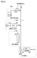
- FIG. 2 is a diagram schematically showing the configurations of the separation device 100 and the pretreatment unit 220.
- the eluent is produced by feeding pure water and a phosphate buffer solution by separate pumps and mixing them in the flow path F.
- the separation device 100 includes a first solvent feeding section 130 for feeding water and a second solvent feeding section 140 for feeding a phosphoric acid buffer solution (phosphoric acid eluent).
- a phosphoric acid buffer solution phosphoric acid eluent
- the water sent from the first solvent feeding unit 130 to the column 120 flows to the column 120 as a mobile phase.
- a sample injection unit 110 is provided in the middle of the flow path (first flow path) from the first solvent liquid supply unit 130 to the column 120, and the aqueous sample 2 injected by the sample injection unit 110 is used as the first solvent liquid supply unit.
- the water sent from the 130 is poured into the column 120.
- the second solvent liquid feeding unit 140 is connected to a flow path (first flow path) from the first solvent liquid feeding unit 130 to the column 120 via a flow path (second flow path) through which the phosphate buffer solution flows. ..
- the flow path (first flow path) from the first solvent liquid feeding section 130 to the column 120 is provided with a peak mixer 111 (first mixer) provided downstream of the sample injection section 110 and upstream of the sample injection section 110. It has an LC mixer 112 (second mixer).
- the second solvent feeding unit 140 is connected by a peak mixer 111 instead of the LC mixer 112, and the phosphate buffer solution is merged with the water (solvent, mobile phase) into which the aqueous sample 2 is injected by the sample injection unit 110.
- the second solvent feeding unit 140 can be connected by an LC mixer 112, and the phosphate buffer solution can be merged with the water before the aqueous sample 2 is injected.
- the ionic strength of the phosphate buffer and the aqueous sample are significantly different, so that the ionic strength of the aqueous sample is the ion of the eluent. It is necessary to adjust in advance so that it is equivalent to the strength.
- the polymer concentration of the water-based sample 2 decreases with the passage of time. It is considered that the decrease in the polymer concentration of the water-based sample 2 is due to the precipitation of the polymer of the water-based sample 2 due to the addition of phosphoric acid in order to adjust the ionic strength. Further, since the polymer concentration of the water-based sample 2 decreases with the passage of time, it is not possible to adopt an apparatus configuration in which the time from setting the water-based sample 2 such as an auto sampler to the measurement becomes long.
- the second solvent feeding unit 140 is connected to the peak mixer 111 instead of the LC mixer 112, and the water system sample 2 is injected with phosphoric acid by the sample injection unit 110. Merge the buffers. That is, in the inspection device 1, the phosphate buffer solution is merged with the aqueous sample 2 from the sample injection section 110 to the column 120.
- the space from the sample injection unit 110 to the column 120 may be any position of the flow path from the sample injection unit 110 to the column 120.
- the phosphate buffer solution is merged with the water-based sample 2 from the sample injection unit 110 to the column 120, so that the ionic strength of the water-based sample 2 does not need to be adjusted in advance, and the polymer of the water-based sample 2 is used. It is possible to suppress the change in concentration and measure the accurate TOC amount.
- the autosampler 113 is connected to the sample injection unit 110. As a result, the inspection device 1 can set a plurality of water-based samples 2 and automatically measure the TOC amount of each water-based sample 2. Of course, the inspection device 1 may inject each water-based sample 2 from the sample injection unit 110 without connecting the autosampler 113 to the sample injection unit 110.
- the first solvent feeding section 130 and the second solvent feeding section 140 are provided with a first degassing section 132 and a second degassing section 142 as pretreatment sections for degassing the gas dissolved in the solvent, respectively.
- the degassing unit 224 for removing carbon dioxide derived from inorganic carbon includes a container 225, a tube 226 arranged in the container 225, and a vacuum pump 227 for reducing the pressure in the container 225.
- the tube 226 is connected to the flow path F through which the aqueous sample 2 flows.
- the tube 226 is a gas permeable tube and is made of a material that is permeable to gas while impermeable to liquid.
- the tube 226 is typically, but is not limited to, a gas permeable tube made of an amorphous Teflon (registered trademark) resin material, a hollow fiber membrane made of a polytetrafluoroethylene material, and the like.
- the gas in the flow path F moves out of the tube 226, and carbon dioxide derived from inorganic carbon is removed from the aqueous sample 2. If the temperature of the container 225 in which the tube 226 is arranged can be maintained high, the degassing efficiency of carbon dioxide can be improved. Therefore, it is desirable to provide a heat insulating unit that keeps the temperature of the container 225.
- the inspection device 1 further includes a column oven 60.
- the column oven 60 regulates the temperature of the column 120.
- the container 225 of the degassing unit 224 for removing carbon dioxide derived from inorganic carbon is arranged in the column oven 60. That is, the temperature of the column 120 and the container 225 is adjusted by the column oven 60. That is, the column oven 60 not only regulates the temperature of the column 120, but is also a heat insulating unit that keeps the temperature of the container 225.
- the temperature of the column 120 and the container 225 is adjusted by the column oven 60, but if the device can maintain the temperature of the column 120 and the container 225, another device can be used instead. May be good.
- FIG. 3 is a diagram schematically showing the configuration of the oxidized portion 242.
- the oxidizing unit 242 includes an adding unit 422 and an irradiation unit 424.
- the addition unit 422 is provided at the entrance of the oxidation unit 242.
- the irradiation unit 424 is provided downstream of the addition unit 422.
- Addition unit 422 adds an oxidizing agent to the aqueous sample 2 (eluent) after removing the inorganic carbon.
- the oxidizing agent is, for example, sodium persulfate.
- the addition unit 422 sends the oxidant to the flow path F by the pump P.
- the irradiation unit 424 includes a UV lamp 426 that irradiates the aqueous sample 2 (eluate) flowing through the flow path F with ultraviolet rays.
- the configuration of the irradiation unit 424 includes a cylindrical UV lamp and a spiral flow path that receives ultraviolet rays from the UV lamp.
- An inflow section 500 is provided in the flow path F between the addition section 422 and the irradiation section 424.
- the inflow section 500 controls the flow rate of a carbon-free gas to flow into the flow path F.
- the carbon-free gas is, for example, nitrogen, helium, oxygen and the like. In this embodiment, the carbon-free gas is nitrogen.
- the inflow unit 500 includes a nitrogen supply source 520 and a mass flow controller 540. Nitrogen gas is supplied to the flow path F from the nitrogen supply source 520. The mass flow controller 540 controls the flow rate of the nitrogen gas supplied to the flow path F.
- the mass flow controller 540 controls the flow rate of nitrogen gas so that the flow rate of nitrogen gas supplied from the nitrogen supply source 520 to the flow path F becomes constant.
- FIG. 4 is a diagram schematically showing the configuration of the inspection device 1a according to the modified example.
- the inspection device 1 includes only the TOC device 200 as a measuring device.
- the inspection device 1 may include another measuring device in addition to the TOC device 200.
- the inspection device 1a according to the modified example is different from the inspection device 1 shown in the above embodiment in that it further includes an ultraviolet-visible spectrophotometer 12 and a fluorescence photometer 14 in addition to the TOC device 200.
- the ultraviolet-visible spectrophotometer 12 and the fluorescence photometer 14 are provided on the flow path F between the separation device 100 and the TOC device 200. More specifically, the ultraviolet-visible spectrophotometer 12 and the fluorometer 14 are provided between the path from the column 120 to the addition section 222.
- the amount of TOC is measured by measuring carbon dioxide derived from organic carbon by applying a chemical treatment to an aqueous sample.
- the water-based sample is measured without physically or chemically treating the water-based sample and without changing the composition, shape, or function of the substance. Can be done.
- each measuring device can be arranged on one flow path, and the eluents eluted from the separation device 100 can be arranged. There is no need to branch to the measuring device. Therefore, it is not necessary to reduce the liquid volume of the water-based sample used in each measuring device, and the measurement accuracy can be maintained.
- the inspection device 1a includes an ultraviolet-visible spectrophotometer 12 and a fluorescence photometer 14.
- the inspection device may be configured to include one of the ultraviolet-visible spectrophotometer 12 and the fluorescence photometer 14 in addition to the TOC device 200.
- the inspection device (1, 1a) is an inspection device for inspecting the aqueous sample (2), and has a first flow path for flowing the aqueous sample and a phosphate eluent.
- the second flow path the separation device (100) that separates the substances contained in the aqueous sample according to the size, and the substances separated according to the size by the separation device.
- Each substance is oxidized and contained in each substance.
- the separation device includes a column (120) for size exclusion chromatography and an introduction unit (110) for introducing an aqueous sample into the mobile phase flowing through the first flow path.
- the second flow path is connected to the first flow path between the column and the introduction part, and the phosphate eluent is merged with the aqueous sample from the introduction part to the column.
- the second flow path is connected between the column and the introduction part, and the phosphate eluent is merged with the aqueous sample from the introduction part to the column. It is possible to accurately measure the TOC amount by suppressing the change in the polymer concentration of the water-based sample without the need for adjusting the ionic strength of the water-based sample.
- the separation device is provided downstream of the introduction part and further includes a first mixer (111) for mixing a solvent in the mobile phase, and the first mixer is a first mixer.
- the second flow path is connected, and the phosphoric acid eluent from the second flow path is mixed with the mobile phase into which the aqueous sample is introduced.
- the phosphoric acid eluent from the second flow path can be mixed with the mobile phase into which the aqueous sample is introduced by the first mixer, and the change in the polymer concentration of the aqueous sample can be observed. It can be suppressed and the accurate TOC amount can be measured.
- the separation device is provided upstream of the introduction unit and further includes a second mixer (112) for mixing the solvent with the mobile phase.
- the solvent can be mixed with the mobile phase before the aqueous sample is introduced by the second mixer.
- a plurality of water-based samples can be set and the TOC amount of each water-based sample can be automatically measured.
- an ultraviolet-visible spectrophotometer (12) and a spectroscope are provided between the flow paths from the separation device to the TOC device. Further equipped with at least one of the fluorescence altimeters (14).
- the measurement can be performed by each measuring device without branching the aqueous sample eluted from the column to each measuring device. Since it is not necessary to branch the water-based sample eluted from the column to each measuring device, the liquid volume of the water-based sample used in each measuring device can be maintained, and as a result, the measurement accuracy can be maintained.
- 1,1a inspection device 2 water-based sample, 12 ultraviolet visible spectrophotometer, 14 fluorescence photometer, 60 column oven, 100 separation device, 110 sample injection section, 120 column, 130 first solvent delivery section, 132 first removal Air part, 140 second solvent feeding part, 142 second degassing part, 200 TOC device, 220 pretreatment part, 222 addition part, 224 degassing part, 225 container, 226 tube, 227 vacuum pump, 240 measuring part, 242 Oxidation part, 244 Gas-liquid separation part, 246 CO2 detector, F flow path, M mixer, P pump.
Landscapes
- Chemical & Material Sciences (AREA)
- Health & Medical Sciences (AREA)
- Life Sciences & Earth Sciences (AREA)
- Physics & Mathematics (AREA)
- Analytical Chemistry (AREA)
- Pathology (AREA)
- Biochemistry (AREA)
- General Health & Medical Sciences (AREA)
- General Physics & Mathematics (AREA)
- Immunology (AREA)
- Food Science & Technology (AREA)
- Medicinal Chemistry (AREA)
- Engineering & Computer Science (AREA)
- Spectroscopy & Molecular Physics (AREA)
- Chemical Kinetics & Catalysis (AREA)
- Molecular Biology (AREA)
- Investigating Or Analyzing Non-Biological Materials By The Use Of Chemical Means (AREA)
Abstract
Description
図1は、実施の形態の検査装置1の構成を模式的に示す図である。検査装置1は、水系試料2を検査するための装置である。図1を参照して、検査装置1は、分離装置100とTOC装置200(測定部)とを備える。検査装置1は、分離装置100によって水系試料2中の物質を大きさに応じて分離し、大きさに応じた順で分離装置100から溶出される各物質を酸化させ、各物質に含まれる有機炭素の量(TOC量)をTOC装置200によって測定する。これにより、検査装置1は、大きさの異なる水系試料2中の溶存有機物ごとにTOC量を測定する。
図2は、分離装置100および前処理部220の構成を模式的に示す図である。本実施の形態において、溶離液は、純水とリン酸緩衝溶液とを別々のポンプで送液し、流路F内で混合させることで生成される。
図3は、酸化部242の構成を模式的に示す図である。酸化部242は、添加部422と、照射部424とを備える。添加部422は、酸化部242の入り口に設けられている。照射部424は、添加部422の下流に設けられている。
図4は、変形例にかかる検査装置1aの構成を模式的に示す図である。上記実施の形態において、検査装置1は、測定装置として、TOC装置200だけを備えている。なお、検査装置1は、TOC装置200に加えて他の測定装置を備えていてもよい。変形例にかかる検査装置1aは、TOC装置200に加えて、紫外可視分光光度計12および蛍光光度計14をさらに備える点で上記実施の形態に示した検査装置1と異なる。
上述した複数の例示的な実施形態は、以下の態様の具体例であることが当業者により理解される。
Claims (5)
- 水系試料を検査するための検査装置であって、
前記水系試料を流す第1流路と、
リン酸溶離液を流す第2流路と、
前記水系試料に含有される物質群を大きさに応じて分離する分離装置と、
前記分離装置で大きさに応じて分離した各物質を酸化させ、各物質に含まれる有機炭素を測定する測定部とを備え、
前記分離装置は、
サイズ排除クロマトグラフィー用のカラムと、
前記第1流路に流す移動相に前記水系試料を導入する導入部と、を含み、
前記第2流路は、前記カラムと前記導入部との間の前記第1流路に接続され、前記導入部から前記カラムに至る間の前記水系試料に前記リン酸溶離液を合流させる、検査装置。 - 前記分離装置は、
前記導入部の下流に設けられ、移動相に溶媒を混合する第1ミキサをさらに備え、
前記第1ミキサは、
前記第2流路が接続され、
前記水系試料を導入した移動相に前記第2流路からの前記リン酸溶離液を混合させる、請求項1に記載の検査装置。 - 前記分離装置は、
前記導入部の上流に設けられ、移動相に溶媒を混合する第2ミキサをさらに備える、請求項2に記載の検査装置。 - 前記導入部で導入する前記水系試料は、オートサンプラから供給される、請求項1に記載の検査装置。
- 前記分離装置から前記測定部に至る流路の間に、紫外可視分光光度計および分光蛍光高度計のうちの少なくとも一方をさらに備えた、請求項1に記載の検査装置。
Priority Applications (4)
| Application Number | Priority Date | Filing Date | Title |
|---|---|---|---|
| US18/005,501 US12306145B2 (en) | 2020-07-17 | 2021-07-15 | Inspection apparatus |
| JP2022536438A JP7400979B2 (ja) | 2020-07-17 | 2021-07-15 | 検査装置 |
| CN202180060673.4A CN116134313B (zh) | 2020-07-17 | 2021-07-15 | 检查装置 |
| EP21842212.9A EP4184162A4 (en) | 2020-07-17 | 2021-07-15 | INSPECTION DEVICE |
Applications Claiming Priority (2)
| Application Number | Priority Date | Filing Date | Title |
|---|---|---|---|
| JP2020-122726 | 2020-07-17 | ||
| JP2020122726 | 2020-07-17 |
Publications (1)
| Publication Number | Publication Date |
|---|---|
| WO2022014666A1 true WO2022014666A1 (ja) | 2022-01-20 |
Family
ID=79555665
Family Applications (1)
| Application Number | Title | Priority Date | Filing Date |
|---|---|---|---|
| PCT/JP2021/026574 Ceased WO2022014666A1 (ja) | 2020-07-17 | 2021-07-15 | 検査装置 |
Country Status (5)
| Country | Link |
|---|---|
| US (1) | US12306145B2 (ja) |
| EP (1) | EP4184162A4 (ja) |
| JP (1) | JP7400979B2 (ja) |
| CN (1) | CN116134313B (ja) |
| WO (1) | WO2022014666A1 (ja) |
Cited By (1)
| Publication number | Priority date | Publication date | Assignee | Title |
|---|---|---|---|---|
| US20230051070A1 (en) * | 2021-08-12 | 2023-02-16 | Roche Diagnostics Operations, Inc. | Sample input interface |
Citations (1)
| Publication number | Priority date | Publication date | Assignee | Title |
|---|---|---|---|---|
| JP2019178902A (ja) | 2018-03-30 | 2019-10-17 | 株式会社エコロ | Toc計測方法及びそれに使用するtoc計測装置 |
Family Cites Families (9)
| Publication number | Priority date | Publication date | Assignee | Title |
|---|---|---|---|---|
| US20080220533A1 (en) * | 2005-05-26 | 2008-09-11 | Shimadzu Corporation | Measuring Method for Total Organic Carbon, Measuring Method for Total Nitrogen and Measuring Apparatus for the Methods |
| KR100927847B1 (ko) * | 2009-03-02 | 2009-11-23 | 정성봉 | 총 유기탄소 분석기 |
| CN102428362B (zh) * | 2009-04-24 | 2015-02-25 | 株式会社岛津制作所 | 具有系统空白功能的总有机碳测量仪 |
| JP5267491B2 (ja) * | 2010-03-15 | 2013-08-21 | 三菱化学株式会社 | 糖鎖分離方法、検体分析方法、液体クロマトグラフィー装置、並びに糖鎖分析方法及び糖鎖分析装置 |
| GB2552398B (en) * | 2016-01-25 | 2020-07-29 | Waters Technologies Corp | Multi-dimensional chromatographic system for analyzing multiple sample components |
| US10620171B2 (en) * | 2017-08-31 | 2020-04-14 | Agilent Technologies, Inc. | Methods of liquid chromatography for anionic compounds |
| CN109406705B (zh) * | 2018-11-29 | 2024-04-09 | 南京大学 | 一种液相色谱联用型有机碳检测器及其使用方法 |
| CN110082447B (zh) * | 2019-05-09 | 2024-05-31 | 同济大学 | 同步表征水样溶解性有机质结构/理化/浓度特性的仪器 |
| WO2021226043A1 (en) * | 2020-05-07 | 2021-11-11 | Waters Technologies Corporation | Multidimensional liquid chromatography system |
-
2021
- 2021-07-15 EP EP21842212.9A patent/EP4184162A4/en active Pending
- 2021-07-15 CN CN202180060673.4A patent/CN116134313B/zh active Active
- 2021-07-15 US US18/005,501 patent/US12306145B2/en active Active
- 2021-07-15 WO PCT/JP2021/026574 patent/WO2022014666A1/ja not_active Ceased
- 2021-07-15 JP JP2022536438A patent/JP7400979B2/ja active Active
Patent Citations (1)
| Publication number | Priority date | Publication date | Assignee | Title |
|---|---|---|---|---|
| JP2019178902A (ja) | 2018-03-30 | 2019-10-17 | 株式会社エコロ | Toc計測方法及びそれに使用するtoc計測装置 |
Non-Patent Citations (3)
| Title |
|---|
| KAWASAKI NOBUYUKI 武: "3C05: Examination of molecular weight distribution of DOC in Kasumigaura using size exclusion chromatography with TOC detector.", PROCEEDINGS OF 72ND GENERAL ASSEMBLY OF THE JAPANESE SOCIETY OF LIMNOLOGY, JAPANESE SOCIETY OF LIMNOLOGY, JP, 1 September 2007 (2007-09-01), JP, XP055888921 * |
| NOBUYUKI KAWASAKIKAZUO MATSUSHIGEAKIO IMAIKAZUHIRO KOMATSUFUMIKAZU OGISHIMASATO YAHATAHIROHISA MIKAMITAKESHI GOTO: "Consideration for molecular weight distribution of DOC in Kasumigaura using size-exclusion chromatography equipped with TOC detector", THE JAPANESE SOCIETY OF LIMNOLOGY, THE 72ND MEETING, September 2007 (2007-09-01) |
| See also references of EP4184162A4 |
Cited By (1)
| Publication number | Priority date | Publication date | Assignee | Title |
|---|---|---|---|---|
| US20230051070A1 (en) * | 2021-08-12 | 2023-02-16 | Roche Diagnostics Operations, Inc. | Sample input interface |
Also Published As
| Publication number | Publication date |
|---|---|
| CN116134313B (zh) | 2024-10-29 |
| CN116134313A (zh) | 2023-05-16 |
| JP7400979B2 (ja) | 2023-12-19 |
| US12306145B2 (en) | 2025-05-20 |
| EP4184162A1 (en) | 2023-05-24 |
| JPWO2022014666A1 (ja) | 2022-01-20 |
| EP4184162A4 (en) | 2024-08-14 |
| US20230288382A1 (en) | 2023-09-14 |
Similar Documents
| Publication | Publication Date | Title |
|---|---|---|
| US8448493B2 (en) | Gas chromatograph-combustion system and method for mass spectrometry | |
| KR0153517B1 (ko) | 저농도 가스혼합물의 제조방법 및 그것의 제조장치 | |
| US5106754A (en) | Zero gravity compatible total organic and inorganic carbon analyzer | |
| US20080318333A1 (en) | Method and System for Measurement of Nitrite and Nitric Oxide Release | |
| JP6947463B1 (ja) | 流れ分析装置及び流れ分析方法 | |
| WO2022014666A1 (ja) | 検査装置 | |
| JP2001356094A (ja) | 気体流れ中の不純物を分析するための方法 | |
| CN101071104B (zh) | 烟草中的氯含量的测定方法 | |
| CN109061026B (zh) | 一种对合成的peek样品进行分析检测的方法 | |
| WO2022014664A1 (ja) | 検査方法および検査装置 | |
| WO2007091654A1 (ja) | 液体クロマトグラフィ装置 | |
| CN103063656A (zh) | 焦化废水中总氮的仪器法测定方法 | |
| Vitenberg et al. | Gas-chromatographic headspace analysis: Metrological aspects | |
| WO2022014665A1 (ja) | 検査装置 | |
| CA2543456A1 (en) | A fast system for detecting detectible combustion products and method for making and using same | |
| WO2021205953A1 (ja) | 流れ分析装置及び流れ分析方法 | |
| CN117783040A (zh) | 一种在线测量有机液体中过氧化氢异丙苯含量的方法 | |
| JP3896795B2 (ja) | 窒素濃度測定装置 | |
| Nitschke et al. | A dual-polarity ion mobility spectrometer for capturing hyper-fast chromatographic peaks | |
| JP7368027B1 (ja) | 流れ分析装置および流れ分析法 | |
| JP7234202B2 (ja) | 溶存無機炭素(dic)の濃度、並びにその同位体炭素及び酸素組成を連続的に分析するための装置並びに方法 | |
| Zhang et al. | Membrane-based cavity ringdown spectroscopy for enhanced sensitivity of isoprene detection | |
| JPH06288923A (ja) | 水中のシリカ成分の分析装置 | |
| Galban et al. | Integrated analytical pervaporation–gas-phase absorptiometry: theoretical aspects and applications | |
| US20240377367A1 (en) | Gas-Liquid Separator, Total Organic Carbon Analyzer, and Analysis System |
Legal Events
| Date | Code | Title | Description |
|---|---|---|---|
| 121 | Ep: the epo has been informed by wipo that ep was designated in this application |
Ref document number: 21842212 Country of ref document: EP Kind code of ref document: A1 |
|
| ENP | Entry into the national phase |
Ref document number: 2022536438 Country of ref document: JP Kind code of ref document: A |
|
| NENP | Non-entry into the national phase |
Ref country code: DE |
|
| ENP | Entry into the national phase |
Ref document number: 2021842212 Country of ref document: EP Effective date: 20230217 |
|
| WWG | Wipo information: grant in national office |
Ref document number: 18005501 Country of ref document: US |