WO2022018819A1 - Dispositif de source de lumière - Google Patents
Dispositif de source de lumière Download PDFInfo
- Publication number
- WO2022018819A1 WO2022018819A1 PCT/JP2020/028228 JP2020028228W WO2022018819A1 WO 2022018819 A1 WO2022018819 A1 WO 2022018819A1 JP 2020028228 W JP2020028228 W JP 2020028228W WO 2022018819 A1 WO2022018819 A1 WO 2022018819A1
- Authority
- WO
- WIPO (PCT)
- Prior art keywords
- light
- light source
- optical axis
- axis direction
- deflection element
- Prior art date
- Legal status (The legal status is an assumption and is not a legal conclusion. Google has not performed a legal analysis and makes no representation as to the accuracy of the status listed.)
- Ceased
Links
Images







Classifications
-
- F—MECHANICAL ENGINEERING; LIGHTING; HEATING; WEAPONS; BLASTING
- F21—LIGHTING
- F21V—FUNCTIONAL FEATURES OR DETAILS OF LIGHTING DEVICES OR SYSTEMS THEREOF; STRUCTURAL COMBINATIONS OF LIGHTING DEVICES WITH OTHER ARTICLES, NOT OTHERWISE PROVIDED FOR
- F21V5/00—Refractors for light sources
-
- F—MECHANICAL ENGINEERING; LIGHTING; HEATING; WEAPONS; BLASTING
- F21—LIGHTING
- F21V—FUNCTIONAL FEATURES OR DETAILS OF LIGHTING DEVICES OR SYSTEMS THEREOF; STRUCTURAL COMBINATIONS OF LIGHTING DEVICES WITH OTHER ARTICLES, NOT OTHERWISE PROVIDED FOR
- F21V5/00—Refractors for light sources
- F21V5/04—Refractors for light sources of lens shape
-
- G—PHYSICS
- G02—OPTICS
- G02F—OPTICAL DEVICES OR ARRANGEMENTS FOR THE CONTROL OF LIGHT BY MODIFICATION OF THE OPTICAL PROPERTIES OF THE MEDIA OF THE ELEMENTS INVOLVED THEREIN; NON-LINEAR OPTICS; FREQUENCY-CHANGING OF LIGHT; OPTICAL LOGIC ELEMENTS; OPTICAL ANALOGUE/DIGITAL CONVERTERS
- G02F1/00—Devices or arrangements for the control of the intensity, colour, phase, polarisation or direction of light arriving from an independent light source, e.g. switching, gating or modulating; Non-linear optics
- G02F1/01—Devices or arrangements for the control of the intensity, colour, phase, polarisation or direction of light arriving from an independent light source, e.g. switching, gating or modulating; Non-linear optics for the control of the intensity, phase, polarisation or colour
- G02F1/13—Devices or arrangements for the control of the intensity, colour, phase, polarisation or direction of light arriving from an independent light source, e.g. switching, gating or modulating; Non-linear optics for the control of the intensity, phase, polarisation or colour based on liquid crystals, e.g. single liquid crystal display cells
- G02F1/133—Constructional arrangements; Operation of liquid crystal cells; Circuit arrangements
- G02F1/1333—Constructional arrangements; Manufacturing methods
- G02F1/1335—Structural association of cells with optical devices, e.g. polarisers or reflectors
- G02F1/1336—Illuminating devices
-
- F—MECHANICAL ENGINEERING; LIGHTING; HEATING; WEAPONS; BLASTING
- F21—LIGHTING
- F21Y—INDEXING SCHEME ASSOCIATED WITH SUBCLASSES F21K, F21L, F21S and F21V, RELATING TO THE FORM OR THE KIND OF THE LIGHT SOURCES OR OF THE COLOUR OF THE LIGHT EMITTED
- F21Y2115/00—Light-generating elements of semiconductor light sources
- F21Y2115/10—Light-emitting diodes [LED]
Definitions
- This disclosure relates to a light source device, and particularly to a light source device having improved light utilization efficiency.
- Patent Document 1 describes a light source having a plurality of light emitting points, a collimating lens that parallelizes the emitted light from the light source, and a plurality of light sources having different inclination angles with respect to the main surface and for each of the plurality of emitted light.
- a light source unit composed of an optical element having an incident surface of the above is disclosed.
- Patent Document 1 discloses, in particular, a configuration in which an optical element has a plurality of mirrors provided with an incident surface in order to realize miniaturization of a light source unit.
- Patent Document 1 In the configuration using a mirror as in Patent Document 1, if the light amount distribution of the parallelized light rays emitted from the collimating lens becomes non-uniform with respect to the optical axis, the light utilization efficiency on the optical axis decreases. However, Patent Document 1 does not consider the decrease in light utilization efficiency on the optical axis due to the apparent tilt of the light source.
- the present disclosure has been made to solve the above problems, and an object of the present disclosure is to provide a light source device having improved light utilization efficiency on the optical axis.
- the light source device includes a parallelizing lens for parallelizing incident light and a plurality of light sources arranged apart from each other in a direction away from the optical axis of the parallelizing lens, and the light as a whole is orthogonal to each other.
- a group of light sources that emit light sources having different divergence angles in the first direction and the second direction parallel to the direction away from the axis are arranged between the light source group and the parallelizing lens in the direction of the optical axis.
- the first direction and the second direction in the first direction in which the divergence angle of the light source group is small, the light emitted from each of the plurality of light sources is deflected in a direction away from the optical axis. It is provided with a light deflection element for incident on the parallelizing lens.
- the light source device of the present disclosure it is possible to provide a light source device having high light utilization efficiency on the optical axis.
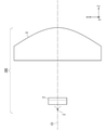
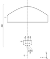
- FIG. 1 It is a figure which shows the schematic structure of the light source apparatus of Embodiment 1. It is a figure which shows the schematic structure of the light source apparatus of Embodiment 1. It is a figure which shows the light distribution characteristic of the light source of the light source apparatus of Embodiment 1.
- FIG. It is a figure which shows an example of the ray tracing of the light source apparatus of Embodiment 1.
- FIG. It is a figure explaining the operation of the light deflection element of the light source apparatus of Embodiment 1.
- FIG. It is a figure which shows the schematic structure when the light deflection element of the light source apparatus of Embodiment 1 is replaced with a mirror. It is a figure which shows the ray tracing result of the light source apparatus of Embodiment 1.
- FIG. It is a figure explaining the inclination angle with respect to the optical axis of the light ray emitted from a light source. It is a figure which shows the back light tracking result of the light source apparatus of Embodiment 1.
- FIG. It is a figure which shows the back light tracking result of the parallelizing lens of the light source apparatus of Embodiment 1.
- FIG. It is a figure which shows the illuminance distribution of the light source apparatus of Embodiment 1.
- FIG. It is a figure which shows the illuminance distribution of the light source apparatus of Embodiment 1.
- FIG. It is a figure which shows the back light tracking result of the mirror of the light source apparatus of Embodiment 1.
- FIG. It is a figure which shows the illuminance distribution of the light source apparatus of Embodiment 1.
- FIG. It is a figure which shows the illuminance distribution of the light source apparatus of Embodiment 1.
- FIG. It is a figure which shows the illuminance distribution of the comparative example of the light source apparatus of Embodiment 1.
- FIG. It is a figure which shows the illuminance distribution of the light source apparatus of Embodiment 1.
- FIG. It is a figure which shows the illuminance distribution of the light source apparatus of Embodiment 1.
- FIG. It is a figure which shows the illuminance distribution of the light source apparatus of Embodiment 1.
- FIG. It is a figure which shows the schematic structure of the modification of the light source apparatus of Embodiment 1.
- FIG. 1 shows a view of the YZ plane observed from the ⁇ X axis side
- FIG. 2 shows a view of the ZX plane observed from the + Y axis direction side.
- the light source device 100 includes a light source group 1, a light deflection element 2, and a parallelizing lens 3, and a light deflection element 2 is arranged between the light source group 1 and the parallelizing lens 3. ing.
- the optical deflection element 2 is provided with optical planes 21 and 22 for optical deflection on the light emitting side, and the optical planes 21 and 22 are tilted together toward the optical axis C1 passing through the center of the parallelizing lens 3. ing.
- the light source group 1 has a light source 1a and a light source 1b arranged in the Y-axis direction as shown in FIG.
- the light source 1a and the light source 1b are solid-state light sources having different divergence angles in the X-axis direction and the divergence angle in the Y-axis direction, and are, for example, laser diodes.
- the XY planes of the light source 1a and the light source 1b are the light emitting surfaces
- the side in the Y-axis direction is longer than the side in the X-axis direction
- the divergence angle in the Y-axis direction (the angle in the ⁇ RX direction) is the divergence in the X-axis direction. It shall be smaller than the angle (angle in the ⁇ RY direction).
- the lengths of the light sources 1a and 1b in the Y-axis direction are 70 ⁇ m, and the length in the X-axis direction is 1 ⁇ m.
- the Y-axis direction having a small divergence angle is also referred to as a first direction
- the X-axis direction is also referred to as a second direction.
- FIG. 3 shows the light distribution characteristics of the light emitted from the light source 1a and the light source 1b.
- the vertical axis indicates the relative light intensity (arbitrary unit)
- the horizontal axis indicates the light divergence angle (°).
- the characteristic 301 shown by the solid line shows the light distribution characteristic of the light diverging in the X-axis direction ( ⁇ RY direction)
- the characteristic 302 shown by the alternate long and short dash line indicates the distribution of the light diverging in the Y-axis direction ( ⁇ RX direction). It shows the optical characteristics.
- the divergence angle in the Y-axis direction is smaller than the divergence angle in the X-axis direction.
- the broken line 303 indicates a position where the relative light intensity is 1 / e 2 , that is, a position where the relative light intensity is about 0.135.
- divergence angle generally laser diode, the relative light intensity to be displayed at an angle position at which the 1 / e 2 number, a measure of the light spread.
- the angle of the position of the characteristic 301 at 1 / e 2 is ⁇ about 37 °
- the angle of the position of the characteristic 302 at the position of 1 / e 2 is ⁇ about 5 °.
- the relative light intensity denote the angular range based on the location of the 1 / e 2.
- the light source 1a and the light source 1b emit, for example, red light having a center wavelength of 638 nm.
- the light source is red as compared with the light source that emits blue light having a center wavelength of, for example, 450 nm and the light source that emits green light having a center wavelength of, for example, 525 nm.
- the light source that emits light is highly sensitive to temperature, and when the temperature rises, the emission efficiency decreases and the wavelength shift occurs.
- the distance between the light sources 1a and the light source 1b that is, the distance in the arrangement direction, that is, the distance in the Y-axis direction in the present embodiment is wide.
- the light utilization efficiency on the optical axis C1 decreases. Therefore, in order to improve the light utilization efficiency, the light source 1a and the light source 1b are of the optical axis C1. It is preferably placed close to each other.
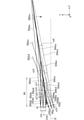
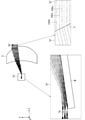
- FIG. 4 is a diagram showing an example of ray tracing.
- FIG. 4 shows an optical system composed of only the light source group 1 and the parallelizing lens 3, and also shows an enlarged view of the region “A” including the light source group 1 and the parallelizing lens 3.
- the light ray 401 emitted from the central portion of the light source 1a is shown by a solid line
- the light ray 402 emitted from the central portion of the light source 1b is shown by a alternate long and short dash line.
- the spread of each light ray in the Y-axis direction was set to ⁇ 5 ° as described with reference to FIG.
- the ray 401 and the ray 402 emitted from the parallelizing lens 3 gradually move away from the optical axis C1 in the arrangement direction of the light source, more specifically, the ray 401 travels in the ⁇ Y axis direction and the ray 402 travels in the + Y axis direction. It can be confirmed that it is.
- the light from the light source group 1 is separated from the optical axis C1 in the arrangement direction of the light sources, and the light utilization efficiency on the optical axis C1 is lowered.
- the array interval from the optical axis C1 to the emission position of each light source is the image height
- the shorter the focal length of the parallelizing lens 3 the higher the image height on the reaching surface, that is, at any position in the Z-axis direction.
- the light beam reaches a position away from the optical axis C1.
- the light beam emitted on the optical axis C1 reaches the vicinity of the optical axis C1 even on the arrival surface.
- the light rays have a width in the ⁇ Y-axis direction due to the influence of the divergence angle of the light source, the light rays parallel to the optical axis C1 also reach the reaching surface, and the width in the ⁇ Y-axis direction is defined. Considering that it has, it was set as "nearby".
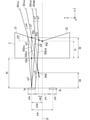
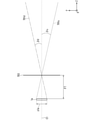
- FIG. 5 is a conceptual diagram illustrating the operation of the light deflection element 2, and the features of the light deflection element 2 will be described with reference to FIG.
- the light deflection element 2 By arranging the light deflection element 2 between the light source 1a and the parallelizing lens 3 (FIG. 1), the light ray 501cc emitted from the central portion of the light source 1a due to the deflection action of the light deflection element 2 is + Y with respect to the optical axis C1. It has an angle ⁇ 1 in the axial direction and can be incident on the parallelizing lens 3.
- a ray traveling in the + Z-axis direction at an angle ⁇ 1 is emitted as a ray parallel to the optical axis C1 by the parallelizing lens 3, so that a decrease in light utilization efficiency on the optical axis C1 can be suppressed.
- the length y1a in the Y-axis direction of the light source 1a is 70 ⁇ m
- the length y1b in the Y-axis direction of the light source 1b is 70 ⁇ m
- the central portion of the light source 1a and the optical axis C1 are in the Y-axis direction.
- the distance y1ac is 105 ⁇ m
- the distance y1c between the ⁇ Y-axis direction end of the light source 1a and the + Y-axis direction end of the light source 1b is 140 ⁇ m
- the distance y1d between the central portion of the light source 1a and the central portion of the light source 1b is 210 ⁇ m. ..
- the distance D1 between the light emitting surface of the light source 1a and the light source 1b and the light incident surface of the light deflection element 2 is 350 ⁇ m, and the thickness T1 of the minimum portion of the light deflection element 2 is 280 ⁇ m.
- the intersection of the light beam parallel to the optical axis C1 and the light incident surface of the optical deflection element 2 in the light emitted from the central portion of the light source 1a is P50
- the optical axis C1 of the light emitted from the central portion of the light source 1a is defined as P50.
- the distance D2 between P50 and P51 is about 315 ⁇ m.
- the material of the light deflection element 2 is, for example, BSC7 of HOYA Corporation, and the refractive index at a wavelength of 638 nm is about 1.515.
- the light ray 501cc is a light ray emitted from the central part of the light source 1a at an angle of 0 °, that is.
- the light ray 501cc emits the central portion of the light source 1a and is incident on the light deflection element 2 at an angle of 0 °. After reaching the emission surface of the light deflection element 2, it is refracted and travels in the + Z axis direction at an angle ⁇ 1.
- the angle ⁇ 1 is calculated by the following mathematical formula (1) using Snell's law. The angle is calculated as an absolute value.
- the incident light is refracted to an angle ⁇ 3 and travels to the emission surface of the light deflection element 2.
- the light travels in the + Z axis direction at an angle ⁇ 4.
- the angle ⁇ 3 is calculated by the following formula (3).
- the angle is calculated as an absolute value.
- the angle ⁇ 4 is calculated by the following formula (4).
- the angle is calculated as an absolute value.
- the incident light is refracted to an angle ⁇ 6 and travels to the emission surface of the light deflection element 2.
- the light On the emission surface of the light deflection element 2, after refraction, the light travels in the + Z axis direction at an angle ⁇ 7.
- the angle ⁇ 6 is calculated by the following formula (6).
- the angle is calculated as an absolute value.
- the angle ⁇ 7 is calculated by the following formula (7).
- the angle is calculated as an absolute value.
- the light ray 501dd preferably passes in the + Y-axis direction from the intersection P52 between the optical axis C1 and the emission surface of the optical deflection element 2.
- the light ray 501cd and the light ray 501dd are in a parallel relationship.
- the light from the light source 1b has a line-symmetrical relationship with the light from the light source 1a with respect to the optical axis C1.
- the light deflection element 2 is a light source arranged on the + side of the optical axis C1 in the arrangement direction of the light sources, and in the present embodiment, the light distribution direction + side (in the present embodiment) with respect to the light from the light source 1a.
- the apparent positions of the light source 1a and the light source 1b in the Y-axis direction can be moved in the optical axis C1 direction.
- the length of the entire apparent light source in the Y-axis direction can be shortened.
- the length y1p in the Y-axis direction of the position P54 is 21 ⁇ m, and the distance D3 between the light source 1a and the position P54 in the Z-axis direction is 214 ⁇ m. Since aberration is generated due to the influence of the light deflection element 2, the position P54 is an approximate position.
- the virtual image height which is the apparent image height of the light source 1a with respect to the optical axis C1. It is possible to set y1p to 21 ⁇ m. That is, the image height after the parallelizing lens 3 is emitted can be reduced to 1/5.
- the light deflection element 2 in this way, it is possible to reduce the apparent image height. This makes it possible to improve the light utilization efficiency in the vicinity of the optical axis C1.
- the angle ⁇ 1 that emits the light deflection element 2 of the light ray 501 cc emitted from the central portion of the light source 1a is preferably as small as possible in consideration of the miniaturization of the parallelizing lens 3 installed in the subsequent stage. Since the parallelizing lens 3 is circular when observed from the XY plane, it is assumed that when the light beam moves in the Y-axis direction, the divergence angle of the light source 1a in the X-axis direction ( ⁇ RY direction) is ⁇ 37 °. This is because there is a high possibility that the amount of light incident on the parallelizing lens 3 will decrease.
- the apparent light source position P54 is moved by 214 ⁇ m in the + Z axis direction from the actual light source position.
- the focal length of the parallelizing lens 3 it becomes necessary to shorten the focal length of the parallelizing lens 3 by 214 ⁇ m. Therefore, the light source image at the condensing position becomes slightly larger.
- the image height 2000 mm away from the parallelized lens 3 is an optical deflection element. It becomes 6.67 mm, which is slightly larger than 6.46 mm when there is no 2. That is, it becomes 1.03 times.
- the effect of such a magnification (1.03 times) is sufficiently smaller than the effect of lowering the image height, that is, the effect of reducing the image height to 1/5 times.
- the calculation formula is shown below.
- the image height 21 ⁇ m ⁇ 2000 mm / 6.5 mm ⁇ 6.46 mm.
- the image height 21 ⁇ m ⁇ 2000 mm / 6.3 mm ⁇ 6.67 mm.
- the distance between the ends of adjacent light sources is 140 ⁇ m, but the same effect can be obtained even if the distance y1c is 70 ⁇ m.
- the interval D1 can be set from 350 ⁇ m to 150 ⁇ m.
- the position of the light deflection element 2 so that the light ray traveling in the + Z-axis direction at an angle ⁇ 5 from the ⁇ Y-axis direction end of the light source 1a, that is, the light ray 501dd in FIG. 5 travels in the + Y-axis direction from P52.
- the length y1a of the light source 1a in the Y-axis direction becomes long
- the light beam traveling in the + Z-axis direction at an angle ⁇ 5 from the end in the ⁇ Y-axis direction of the light source 1a travels in the ⁇ Y-axis direction from P52.
- the interval D1 it is possible to lengthen the interval D1 by changing the material of the light deflection element 2 to a glass material or the like having a high refractive index.
- the angle ⁇ 8 is changed.
- the angle ⁇ 8 may be set so that the angle ⁇ 1 is 10.43 °, and specifically, the angle ⁇ 8 can be set to 12.5 °.
- the interval D1 can be set to 380 ⁇ m in consideration of the change in the back focus length due to the difference in the refractive index.
- the apparent Y-axis direction and Z-axis direction of the light source position P54 change. It becomes necessary to change the position and focus in the Z-axis direction of. If the interval D1, the thickness T1 of the minimum portion of the light deflection element 2, and the angle ⁇ 8 are set so that the apparent Y-axis direction and Z-axis direction positions of the light source position P54 do not change, the Z of the parallelizing lens 3 is set. Eliminates the need to change axial position and focus.
- the same function as that of the light deflection element 2 can be realized by using two mirrors.
- the mirror is tilted by ⁇ 10.43 / 2 ⁇ 5.22 ° with respect to the optical axis C1. More specifically, it is tilted by ⁇ 5.22 ° with respect to the light of the light source 1a arranged on the + Y-axis side and by +5.22 ° with respect to the light of the light source 1b arranged on the ⁇ Y-axis side.
- the divergence angle of the light source 1a is ⁇ 5 °
- a part of the light emitted at ⁇ 5 ° may reach the parallelizing lens 3 without reaching the mirror.
- the light source has a length in the Y-axis direction, which is the arrangement direction, so that the width of the mirror, that is, the length in the Z-axis direction must be longer than the distance to the parallelizing lens 3, the end of the light source,
- the light source 1a is arranged on the + Y-axis side, the light emitted from the end portion in the + Y-axis direction may not reach the mirror.
- FIG. 6 shows a schematic configuration when the light deflection element 2 is replaced by a mirror.
- the length y1a of the light source 1a in the Y-axis direction is 70 ⁇ m
- the distance y1ac in the Y-axis direction between the central portion of the light source 1a and the optical axis C1 is 105 ⁇ m, which is the same as the example of FIG.
- the angle ⁇ 2 and the angle ⁇ 5 are the same as in the example of FIG.
- the tilt angle ⁇ 9 of the mirror M was set to ⁇ 8 °.
- the ray corresponding to the ray 503cu is indicated by the ray 504cu
- the light rays in the ⁇ Z axis direction are represented by the light rays 504 uc, 504 uu, and 504 ud, it can be confirmed that the light rays 503 ud behave as if they are emitted from the light emitting point at the position P55u.
- the light ray 503dc emitted parallel to the optical axis C1
- the angle ⁇ 5 + 5 °.
- the light collecting efficiency of the light source 1a is improved by using the mirror M, the light collecting effect is highest when the following formula (9) is satisfied.
- the following is a conditional expression when the position P55c is on the optical axis C1.
- y1ac / D4 sin (2 ⁇
- the distance D4 between the central portion of the light source 1a and the reflection surface of the mirror M is about 381 ⁇ m.
- the mounting interval D4 allows, for example, an error of 381 ⁇ m ⁇ 10% (38 ⁇ m).
- the diameter of the parallelizing lens 3 can be increased, the substitution of the optical deflection element 2 by the mirror M is not excluded.
- the traveling direction of light can be changed from the + Z-axis direction to the ⁇ X-axis direction and the like. Therefore, by adjusting the inclination of the mirror M or the distances from the light source 1a and the light source 1b to the parallelized lens, in addition to the effect of suppressing the decrease in the light utilization efficiency on the optical axis, the degree of freedom in component arrangement is improved. can.
- the traveling direction of light is changed in the ⁇ X-axis direction
- the mirror surface is tilted in two axes, so the tendency of the emitted light rays changes depending on the center of rotation of the mirror.
- the light beam travels in the X-axis direction without maintaining the spread of the light ray before the reflection.
- the parallelizing lens 3 makes the light emitted from the light deflection element 2 parallel to the optical axis C1.
- the parallelizing lens 3 is formed, for example, in an aspherical shape.
- the aspherical shape can be a toroidal shape having different shapes in the X-axis direction and the Y-axis direction. Further, the light incident surface may have a convex shape or a concave shape.
- the light rays are parallel to the optical axis C1 with respect to the light rays emitted from the central portion of the light source 1a and the central portion of the light source 1b.
- the light rays emitted from the central portion of the light source 1a and the central portion of the light source 1b reach the vicinity of the optical axis C1, and the reached light source image can be minimized.
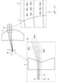
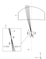
- FIG. 7 is a diagram showing a ray tracing result of a ray emitted from the light source 1a.
- an enlarged view of the region “B” including the light source group 1 and the light deflection element 2 and an enlarged view of the region “C” of the emission surface of the parallelizing lens 3 are shown together.
- the positional relationship between the light source 1a and the light deflection element 2 is as shown in FIG.
- the parallelizing lens 3 is arranged on the + Z axis direction side of the light deflection element 2.
- the focal length of the parallelizing lens is about 6.5 mm.
- a light ray having a spread of ⁇ 5 ° is emitted from the light source 1a in the + Z axis direction.
- the ray tracing results of the ray 601u emitted from the + Y-axis direction end of the light source 1a, the ray 601c emitted from the central portion of the light source 1a, and the ray 601d emitted from the ⁇ Y-axis direction end of the light source 1a are shown.
- the light rays 601u, the light rays 601c, and the light rays 601d emitted from the parallelizing lens 3 are substantially parallel to the optical axis C1.
- FIG. 8 is a diagram illustrating an inclination angle of a light ray actually emitted from the light source 1a with respect to the optical axis C1.
- the parallelizing lens 3 is a virtual thin-walled lens 703, and the focal length F7 is 6.5 mm. It is assumed that the light source 1a is moved so that the central portion of the light source 1a is located on the optical axis C1.
- FIG. 8 shows the behavior of the light rays 701u emitted from the + Y-axis direction end of the light source 1a and the light rays 701d emitted from the ⁇ Y-axis direction end of the light source 1a.
- the angle ⁇ u and the angle ⁇ d of the light ray 701u and the light ray 701d emitted from the thin-walled lens 703 with respect to the optical axis C1 are expressed by the following mathematical formula (10).
- the parallelizing lens 3 is emitted at an angle of 0.31 °, it can be assumed that the light source 1a is emitted from the optical axis C1.
- FIG. 9 shows the result of back light tracing using the configuration of FIG.
- an enlarged view of the region “D” including the light source group 1 and the light deflection element 2 and an enlarged view of the region “E” of the emission surface of the parallelizing lens 3 are shown together.
- the above assumption is confirmed by tracking the back rays of the light rays traveling from the + Z axis direction to the ⁇ Z axis direction of the parallelizing lens 3 and confirming the image formation position.
- FIG. 9 shows the back ray tracing results of the ray 801u, the ray 801c, and the ray 801d, and the ray 801d is incident on the collimated beam 3 at an angle of ⁇ 0.31 ° with respect to the optical axis C1.
- the light ray 801c is incident on the parallelizing lens 3 in parallel with the optical axis C1
- the light ray 801u is incident on the parallelizing lens 3 at an angle of +0.31 ° with respect to the optical axis C1.
- the light rays 801u are focused (imaged) on the + Y-axis direction end of the light source 1a, and the light rays 801c are focused (imaged) on the center of the light source 1a, and the light rays 801d.
- the light ray 801c is an example of condensing light on the central portion of the light source 1a in the Y-axis direction, but the parallelizing lens 3 and the optical deflection when parallel light is incident from the + Z-axis direction side of the parallelizing lens 3.
- the condensing position of the parallel light by the optical system including the element 2 does not have to be exactly located on the light emitting surface of each of the light source 1a and the light source 1b.
- the central portions of the light source 1a and the light source 1b are within ⁇ y1a / 3 from the center in the Y-axis direction and ⁇ 30 ⁇ m from the light emitting surface of the light source 1a in the Z-axis direction. It may preferably contain ⁇ 10 ⁇ m or less.
- the position in the Y-axis direction of the position P54 is the image height position of the light source 1a, but in FIG. 9, the behavior of the light ray such that the central portion of the light source 1a is located on the optical axis C1. I am doing.
- the shape of the parallelizing lens 3 is set so that the light rays are concentrated at the position P54 when the light rays parallel to the optical axis C1 are incident on the parallelizing lens 3 from the + Z axis direction.
- the focal position of the parallelizing lens 3 is in the ⁇ Z axis direction from the position P54, but it is possible to make the optical axis C1 behave as a light ray in which the central portion of the light source 1a is arranged.
- FIG. 10 is a diagram showing a back light ray tracking result when a light ray parallel to the optical axis C1 is incident from the + Z axis direction of the parallelizing lens 3.
- FIG. 10 an enlarged view of the region “F” including the light source group 1 is also shown.
- the focusing point P80 of the parallelizing lens 3 is on the + Z axis direction side from the light source 1a and on the + Y axis direction side from the optical axis C1.
- the focal position P80f of the parallelizing lens 3 is on the ⁇ Z axis direction side from the focusing point P80.
- the focal position P80f is located on the + Z axis side of the light source 1a because the back focus of the parallelizing lens 3 is shortened due to the influence of the optical deflection element 2 which is an optical element. It is also considered that the angle ⁇ 1 is affected by the deflection of the light beam.
- the distance between the focusing point P80 and the focal position P80f in the Z-axis direction is about 140 ⁇ m.
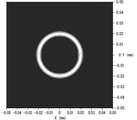
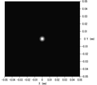
- FIG. 10 the illuminance distributions on the condensing point P80 and the focal position P80f when the parallel light flux is incident on the + Z axis side of the parallelizing lens 3 in the ⁇ Z axis direction are shown in FIGS. 11 and 12, respectively.
- the X-axis (mm) is shown on the horizontal axis and the Y-axis (mm) is shown on the vertical axis, and the light intensity is divided into five gradations. The brightest white color represents 100% intensity.
- FIG. 11 it can be seen that a ring-shaped illuminance distribution with a hollow center is formed on the condensing point P80, and the intensity is strong in the vicinity of a region having a radius of 20 ⁇ m.
- FIG. 12 it can be seen that on the focal position P80f, a concentric illuminance distribution is formed and a small condensing spot is formed to be the focal position.
- the optical surfaces 21 and 22 for light deflection are provided on the light emitting side of the light deflection element 2, but there is also a case where the optical surfaces 21 and 22 for light deflection are provided on the light incident side.
- a similar effect can be obtained. It should be noted that the effect of improving the light utilization efficiency on the optical axis C1 can be obtained without forming a ring-shaped region having a strong light intensity. Further, even in the configuration using the mirror M shown in FIG. 6, a ring-shaped illuminance distribution can be formed.
- FIG. 13 shows the result of back light tracing of the configuration using the mirror M shown in FIG.
- an enlarged view of the region “G” including the light source group 1 and the mirror M and an enlarged view of the region “F” of the emission surface of the parallelizing lens 3 are shown together.
- FIG. 13 shows the back ray tracing result when the ray 1101u, the ray 1101c, and the ray 1101d are incident from the + Z axis direction of the parallelizing lens 3.
- the ray 1101u is incident on the parallelizing lens 3 at an angle ⁇ 0.31 ° with respect to the optical axis C1
- the ray 1101c is incident on the parallelizing lens 3 parallel to the optical axis C1
- the ray 1101d is emitted.
- It is incident on the parallelizing lens 3 at an angle of +0.31 ° with respect to the optical axis C1.
- the light ray 1101u is focused (imaged) on the + Y-axis end of the light source 1a
- the light ray 1101c is focused (imaged) on the center of the light source 1a
- the light ray 1101d is focused on the light source 1a. It can be seen that the light source is focused (imaging) at the end in the Y-axis direction.
- the light ray 1101u is focused in the ⁇ Z axis direction as compared with the light collecting position of the light ray 1101c.
- the light ray 1101d is focused in the + Z axis direction as compared with the light collecting position of the light ray 1101c. That is, since the condensing position in the Y-axis direction shifts in the Z-axis direction as compared with the case where the light deflection element 2 is used, in the light beam emitted from the light source 1a, at an arbitrary reaching surface after the parallelizing lens 3 is emitted. It can be seen that the light beam width of is non-uniform in the Y-axis direction.
- FIG. 9 which is the result of back light tracing using the configuration of FIG. 5, and FIG. 13 which is the result of back light tracking using the configuration of FIG. 6, the evaluation surface (XY plane) at a distance of 2000 mm from the light source 1a.
- 14 to 16 show the illuminance distribution of the light emitted from the light source 1a. From FIG. 3, the divergence angle of the light source 1a is ⁇ about 37 ° for 1 / e 2 in the X-axis direction (RY direction) and ⁇ about 5 ° for 1 / e 2 in the Y-axis direction (RX direction). ..
- FIGS. 14 to 16 an X-axis (mm) is shown on the horizontal axis and a Y-axis (mm) is shown on the vertical axis, and the light intensity is divided into five gradations. The brightest white color represents 100% intensity.
- FIG. 14 shows the illuminance distribution of light when the light deflection element 2 is used
- FIG. 15 shows the light illuminance distribution when the mirror M is used. From FIG. 14, when the light axis C1 is 0 mm in the Y-axis direction, the region where the light intensity is 80% (80% when the maximum light intensity is 100%) or more is continuously 8.4 mm to + 10.1 mm ( It can be seen that the light reaches the range of 18.5 mm) uniformly. Further, it can be seen that the region where the light intensity is 20% or more with the maximum light intensity as 100% is in the range of -10.3 mm to +12.3 mm (22.6 mm). From this, the ratio of the range in the Y-axis direction of the uniform region of 80% or more to the region of light intensity of 20% or more is about 81.9% (18.5 mm / 22.6 mm).
- the image height of the light source 1a is as follows. It is expressed by the formula (11).
- the illuminance range in the Y-axis direction is slightly less than +10.7 mm on the + side from the region of light intensity of 20% or more, but is within -10.7 mm on the-side. Further, the region of light intensity of 80% or more is within ⁇ 10.7 mm, and considering the ratio of the region of light intensity of 80% to the region of light intensity of 20% or more in the Y-axis direction, the optical axis C1 It is considered that almost the same result as the case where the light source 1a is on the top is obtained.
- the illuminance distribution in the Y-axis direction has a region of light intensity of 80% or more in the range of -9.3 mm to -6.9 mm (2.4 mm) in the Y-axis direction. It can be seen that the region with high light intensity is located at a position away from the optical axis C1. Further, since the range of the light intensity region of 80% or more is narrow, it can be seen that the light having a strong light intensity is concentrated. Further, it can be seen that the light intensity of 20% or more is in the range of -10.2 mm to + 12.8 mm (22.8 mm).
- the light intensity of 40% or more is within the range of ⁇ 10.7 mm, it is considered that the light intensity is generally within ⁇ 10.7 mm.
- the light intensity on the optical axis C1 is lower than the peak position, and the apparent light source 1a is tilted. Conceivable.
- FIG. 16 is a diagram showing an illuminance distribution in the case of the configuration of FIG. 4 in which the light deflection element 2 and the mirror M are not arranged as a comparative example.
- the light intensity region of 20% or more is almost uniformly in the range of ⁇ 42.7 mm to -20.7 mm (22.0 mm).
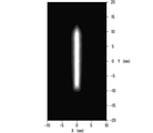
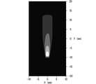
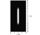
- FIGS. 17 to 19 show the illuminance distribution of the light on the evaluation surface at a distance of 2000 mm from the light source 1a and the light source 1b when both the light source 1a and the light source 1b are turned on.
- the divergence angle of the light source 1a and the light source 1b are both from FIG. 3, 1 / e 2 is approximately ⁇ 37 ° in the X-axis direction (RY direction), 1 / e 2 of the Y-axis direction (RX direction) ⁇ It was set to about 5 °.
- an X-axis (mm) is shown on the horizontal axis and a Y-axis (mm) is shown on the vertical axis, and the light intensity is divided into five gradations. The brightest white color represents 100% intensity.
- FIG. 17 shows the illuminance distribution when the light deflection element 2 is used
- FIG. 18 shows the illuminance distribution when the mirror M is used
- FIG. 19 shows the illuminance distribution when the focal position of the parallelizing lens 3 is moved by 15 ⁇ m in the + Z axis direction using the mirror M. Shows.
- the region where the light intensity is 80% or more is continuously illuminated uniformly in the range of -8.9 mm to +8.9 mm (17.8 mm).
- the region where the light intensity is 20% or more is in the range of -11.5 mm to +11.6 mm (23.1 mm).
- the ratio of the range in the Y-axis direction of the uniform region of 80% or more to the region of light intensity of 20% or more is about 77.1% (17.8 mm / 23.1 mm). That is, it can be seen that the light intensity is uniformly distributed in the range of about 77.1% without peak peaks.
- the region where the light intensity is 80% or more is in the range of -2.7 mm to +2.7 mm (5.4 mm). Further, it can be seen that the region where the light intensity is 20% or more is in the range of -10.8 mm to +10.7 mm (21.5 mm). From this, the ratio of the range in the Y-axis direction of the region having a high light intensity of 80% or more to the region having a light intensity of 20% or more is about 25.1% (5.4 mm / 21.5 mm). That is, it can be seen that the region having a light intensity of 80% or more is concentrated in the range of about 25.1%, and the light utilization efficiency on the optical axis C1 is high.
- the light intensity on the optical axis C1 is increased, and the light utilization efficiency in the optical axis C1 direction can be improved as compared with the case of FIG.
- the design of the parallelizing lens 3 is devised so that the light beam 1101u traced by the back light beam is focused near the + Y-axis direction end face of the light source 1a shown in FIG. 13, so that the light utilization efficiency in the optical axis C1 direction is achieved. It means that it is possible to improve.
- the fact that the light beam 1101u traced by the back ray focuses on the vicinity of the + Y-axis direction end face of the light source 1a means that the focusing position (focus position of the parallelizing lens 3) in FIG. 13 moves in the + Z-axis direction. Means.
- FIG. 19 is an example in which the focal position of the parallelizing lens 3 is moved by 15 ⁇ m in the + Z axis direction using the mirror M, the configuration for the light utilization efficiency on the optical axis C1 corresponding to or higher in FIG. 18 is parallel.
- the focal position of the modified lens 3 may be moved by 15 ⁇ m ⁇ 15 ⁇ m in the + Z axis direction.
- FIG. 19 when the width in the Y-axis direction is confirmed in the region where the light intensity is 80% or more, FIG. 19 is 5.4 mm ( ⁇ 2.7 mm) and FIG. 17 is 17.8 mm ( ⁇ 8.9 mm). Therefore, FIG. 19 using the mirror M, which is a reflection type light deflection element, has higher light utilization efficiency on the optical axis C1 than FIG. 17 using the transmission type light deflection element 2. In FIG. 17, since there is no light loss due to the reflectance of the mirror M, the light utilization efficiency is high as a whole, and the light utilization efficiency on the evaluation surface is high.
- the ratio of the range in the Y-axis direction of the region where the light intensity is 80% or more to the region where the light intensity is 20% or more is 75% or more. It is possible to collect uniform light on the optical axis C1 while increasing the light utilization efficiency on the optical axis C1.
- a light intensity uniform element for example, a rod lens and a light pipe
- the number of reflections in the element can be reduced, so that the size (length) of the optical system can be shortened.
- the ratio of the range in the Y-axis direction of the region having a high light intensity of 80% or more to the region having a light intensity of 20% or more is set to 30% or less. This makes it possible to further improve the light utilization efficiency on the optical axis C1.
- the aperture size of a light intensity uniform element for example, a rod lens and a light pipe, is small, it can be incorporated into an optical system with high light utilization efficiency.
- an example of an optical system including a appropriately designed mirror M includes an optical system in which the focal position of the parallelizing lens 3 is adjusted as described above.
- Examples of the method for adjusting the focal position of the parallelizing lens 3 include a method of moving the parallelizing lens 3 in the + Z axis direction or a method of moving the light source group in the ⁇ Z axis direction.
- FIG. 20 is a diagram showing a schematic configuration of a light source device 100A which is a modification of the light source device 100.
- the number of light sources can be three or more.
- a light source 14c third is further placed on the optical axis C1.
- Light source is arranged.
- the light deflection element 20 as shown in FIG. 20 can be used.
- the 20 has a first optical surface 20c having no inclination with respect to a reference plane (XY plane) perpendicular to the optical axis C1 on the optical axis C1, and both sides thereof with respect to a reference plane. It includes a second optical surface 20a and a third optical surface 20b having an inclination.
- the first optical surface 20c emits light rays emitted from the light source 14c from the optical deflection element 20 at the same angle in the + Z axis direction.
- the second optical surface 20a emits a light ray emitted from the light source 14a in the + Z-axis direction at an angle in the + Y-axis direction as in the light ray 501cc in FIG. 5, for example.
- the third optical surface 20b emits a light ray emitted from the light source 14b at an angle in the ⁇ Y axis direction in the + Z axis direction.
- the second optical surface 20a causes the virtual focusing point of the light source 14a to move in the + Z-axis direction
- the third optical surface 20b causes the virtual focusing point of the light source 14b to move in the + Z-axis direction. Moving. Therefore, the following adjustment may be made so as to align the position in the Z-axis direction with the virtual condensing points of both. That is, the first optical surface 20c may be moved in the + Z axis direction to adjust the air conversion length. Further, the light source 14c may be moved in the + Z axis direction.
- FIG. 20 shows an example in which an optical surface for light deflection is arranged on the light incident side, it is also possible to provide the optical surface on the light emitting side. By adopting such a configuration, it is possible to further improve the light utilization efficiency in the vicinity of the optical axis C1.
- the same deflection function by using a mirror.
- no mirror is provided in the portion corresponding to the first optical surface 20c having no inclination, and the second optical surface 20a and the third optical surface 20a and the third optical surface 20a are not provided.
- a mirror will be provided on the portion corresponding to the optical surface 20b of the above.
- the light source 14c may be moved in the + Z-axis direction so as to match the positions of the virtual condensing points of the light source 14a and the light source 14b in the Z-axis direction.
- the "light deflection element" in a broad sense is a member that adjusts the length of the entire apparent light source in the Y-axis direction in the arrangement direction of the light source by deflecting the light by using reflection (this example). Then, the above mirror) is also included.
- a configuration in which the number of light sources is two or more is preferable.
Landscapes
- Physics & Mathematics (AREA)
- Nonlinear Science (AREA)
- Engineering & Computer Science (AREA)
- General Engineering & Computer Science (AREA)
- Mathematical Physics (AREA)
- Chemical & Material Sciences (AREA)
- Crystallography & Structural Chemistry (AREA)
- General Physics & Mathematics (AREA)
- Optics & Photonics (AREA)
- Projection Apparatus (AREA)
- Lenses (AREA)
Abstract
Un dispositif de source de lumière selon la présente invention comprend : une lentille de collimation qui collimate la lumière incidente ; un groupe de sources de lumière qui comprend une pluralité de sources de lumière disposées à distance l'une de l'autre dans une direction opposée à l'axe optique de la lentille de collimation et qui émet globalement un faisceau de lumière ayant un angle de divergence qui diffère dans une première direction et une seconde direction, la première direction et la seconde direction étant perpendiculaires l'une à l'autre et étant chacune parallèle à une direction s'éloignant de l'axe optique ; et un élément de déviation de lumière qui est disposé entre le groupe de sources de lumière et la lentille de collimation dans la direction de l'axe optique et qui dévie la lumière émise à partir de chacune de la pluralité de sources de lumière dans une direction s'éloignant de l'axe optique pour amener la lumière à être incidente sur la lentille de collimation dans la première direction, dans laquelle l'angle de divergence du groupe de sources de lumière est plus petit parmi la première direction et la seconde direction.
Priority Applications (3)
| Application Number | Priority Date | Filing Date | Title |
|---|---|---|---|
| PCT/JP2020/028228 WO2022018819A1 (fr) | 2020-07-21 | 2020-07-21 | Dispositif de source de lumière |
| JP2022538576A JP7446432B2 (ja) | 2020-07-21 | 2021-02-02 | 光源装置 |
| PCT/JP2021/003622 WO2022018891A1 (fr) | 2020-07-21 | 2021-02-02 | Dispositif de source de lumière |
Applications Claiming Priority (1)
| Application Number | Priority Date | Filing Date | Title |
|---|---|---|---|
| PCT/JP2020/028228 WO2022018819A1 (fr) | 2020-07-21 | 2020-07-21 | Dispositif de source de lumière |
Publications (1)
| Publication Number | Publication Date |
|---|---|
| WO2022018819A1 true WO2022018819A1 (fr) | 2022-01-27 |
Family
ID=79729143
Family Applications (2)
| Application Number | Title | Priority Date | Filing Date |
|---|---|---|---|
| PCT/JP2020/028228 Ceased WO2022018819A1 (fr) | 2020-07-21 | 2020-07-21 | Dispositif de source de lumière |
| PCT/JP2021/003622 Ceased WO2022018891A1 (fr) | 2020-07-21 | 2021-02-02 | Dispositif de source de lumière |
Family Applications After (1)
| Application Number | Title | Priority Date | Filing Date |
|---|---|---|---|
| PCT/JP2021/003622 Ceased WO2022018891A1 (fr) | 2020-07-21 | 2021-02-02 | Dispositif de source de lumière |
Country Status (2)
| Country | Link |
|---|---|
| JP (1) | JP7446432B2 (fr) |
| WO (2) | WO2022018819A1 (fr) |
Citations (2)
| Publication number | Priority date | Publication date | Assignee | Title |
|---|---|---|---|---|
| WO2016035349A1 (fr) * | 2014-09-05 | 2016-03-10 | 船井電機株式会社 | Dispositif optique laser et dispositif de projection d'image |
| JP2019129076A (ja) * | 2018-01-25 | 2019-08-01 | スタンレー電気株式会社 | 光照射装置及び車両用灯具 |
Family Cites Families (6)
| Publication number | Priority date | Publication date | Assignee | Title |
|---|---|---|---|---|
| DE19800590B4 (de) * | 1998-01-09 | 2005-12-01 | Jenoptik Ag | Optische Anordnung zur Symmetrierung der Strahlung eines oder mehrerer übereinander angeordneter Hochleistungsdiodenlaser |
| JP6178991B2 (ja) * | 2013-01-24 | 2017-08-16 | パナソニックIpマネジメント株式会社 | 光源ユニットおよびそれを用いた光源モジュール |
| JP2017168253A (ja) * | 2016-03-15 | 2017-09-21 | 株式会社ジャパンディスプレイ | 照明装置及び表示装置 |
| JP2018060720A (ja) * | 2016-10-06 | 2018-04-12 | 三菱電機株式会社 | 前照灯モジュール及び前照灯装置 |
| JP7009910B2 (ja) * | 2017-10-26 | 2022-01-26 | セイコーエプソン株式会社 | 光源装置およびプロジェクター |
| JP6611019B2 (ja) * | 2018-02-27 | 2019-11-27 | ウシオ電機株式会社 | 光源装置、プロジェクタ |
-
2020
- 2020-07-21 WO PCT/JP2020/028228 patent/WO2022018819A1/fr not_active Ceased
-
2021
- 2021-02-02 WO PCT/JP2021/003622 patent/WO2022018891A1/fr not_active Ceased
- 2021-02-02 JP JP2022538576A patent/JP7446432B2/ja active Active
Patent Citations (2)
| Publication number | Priority date | Publication date | Assignee | Title |
|---|---|---|---|---|
| WO2016035349A1 (fr) * | 2014-09-05 | 2016-03-10 | 船井電機株式会社 | Dispositif optique laser et dispositif de projection d'image |
| JP2019129076A (ja) * | 2018-01-25 | 2019-08-01 | スタンレー電気株式会社 | 光照射装置及び車両用灯具 |
Also Published As
| Publication number | Publication date |
|---|---|
| WO2022018891A1 (fr) | 2022-01-27 |
| JP7446432B2 (ja) | 2024-03-08 |
| JPWO2022018891A1 (fr) | 2022-01-27 |
Similar Documents
| Publication | Publication Date | Title |
|---|---|---|
| US20060176912A1 (en) | Apparatus for projecting a line of light from a diode-laser array | |
| US7800765B2 (en) | Light projection optical system and light projection apparatus using the same | |
| JP3222498B2 (ja) | 走査光学系 | |
| JP6964093B2 (ja) | 投影光学系、画像投影装置、および画像投影システム | |
| CN101784939A (zh) | 多光束扫描装置 | |
| JP2017146602A (ja) | レーザビームを成形するための装置 | |
| WO2021147562A1 (fr) | Dispositif de réflexion diffuse | |
| JP6625151B2 (ja) | レーザモジュール | |
| CN114879214A (zh) | 一种光学整形模组、装置及激光雷达系统 | |
| US20220123523A1 (en) | Semiconductor laser device | |
| US5477372A (en) | Optical scanner | |
| US7016380B2 (en) | Multi-beam laser scanning unit | |
| US11662578B2 (en) | Image display device | |
| WO2022018819A1 (fr) | Dispositif de source de lumière | |
| JP5177182B2 (ja) | 光走査装置 | |
| US7106484B2 (en) | Scanning optical system | |
| US10126557B2 (en) | Projection system for generating spatially modulated laser radiation and optical arrangement for transforming laser radiation | |
| JPH05127077A (ja) | シリンドリカルレンズ系 | |
| JP6127238B2 (ja) | 走査光学系 | |
| JP7773264B2 (ja) | 走査光学系 | |
| JP6829514B1 (ja) | 走査光学系の製造方法 | |
| JP2001075035A (ja) | 回折面を用いた走査光学系 | |
| JP2017116701A (ja) | 走査光学系及び走査レンズ | |
| JP2001059946A (ja) | 光走査光学装置及びそれを用いた画像形成装置 | |
| CN120762203A (zh) | 一种小体积的扫描系统 |
Legal Events
| Date | Code | Title | Description |
|---|---|---|---|
| 121 | Ep: the epo has been informed by wipo that ep was designated in this application |
Ref document number: 20946478 Country of ref document: EP Kind code of ref document: A1 |
|
| NENP | Non-entry into the national phase |
Ref country code: DE |
|
| 122 | Ep: pct application non-entry in european phase |
Ref document number: 20946478 Country of ref document: EP Kind code of ref document: A1 |
|
| NENP | Non-entry into the national phase |
Ref country code: JP |