WO2022019011A1 - Dispositif de purification de gaz d'échappement, véhicule de type à selle et procédé de fabrication de dispositif de purification de gaz d'échappement - Google Patents
Dispositif de purification de gaz d'échappement, véhicule de type à selle et procédé de fabrication de dispositif de purification de gaz d'échappement Download PDFInfo
- Publication number
- WO2022019011A1 WO2022019011A1 PCT/JP2021/022917 JP2021022917W WO2022019011A1 WO 2022019011 A1 WO2022019011 A1 WO 2022019011A1 JP 2021022917 W JP2021022917 W JP 2021022917W WO 2022019011 A1 WO2022019011 A1 WO 2022019011A1
- Authority
- WO
- WIPO (PCT)
- Prior art keywords
- exhaust gas
- gas purification
- honeycomb structure
- purification device
- metal honeycomb
- Prior art date
- Legal status (The legal status is an assumption and is not a legal conclusion. Google has not performed a legal analysis and makes no representation as to the accuracy of the status listed.)
- Ceased
Links
Images






Classifications
-
- B—PERFORMING OPERATIONS; TRANSPORTING
- B01—PHYSICAL OR CHEMICAL PROCESSES OR APPARATUS IN GENERAL
- B01J—CHEMICAL OR PHYSICAL PROCESSES, e.g. CATALYSIS OR COLLOID CHEMISTRY; THEIR RELEVANT APPARATUS
- B01J35/00—Catalysts, in general, characterised by their form or physical properties
- B01J35/50—Catalysts, in general, characterised by their form or physical properties characterised by their shape or configuration
- B01J35/56—Foraminous structures having flow-through passages or channels, e.g. grids or three-dimensional [3D] monoliths
- B01J35/57—Honeycombs
-
- B—PERFORMING OPERATIONS; TRANSPORTING
- B01—PHYSICAL OR CHEMICAL PROCESSES OR APPARATUS IN GENERAL
- B01D—SEPARATION
- B01D53/00—Separation of gases or vapours; Recovering vapours of volatile solvents from gases; Chemical or biological purification of waste gases, e.g. engine exhaust gases, smoke, fumes, flue gases, aerosols
- B01D53/34—Chemical or biological purification of waste gases
- B01D53/92—Chemical or biological purification of waste gases of engine exhaust gases
- B01D53/94—Chemical or biological purification of waste gases of engine exhaust gases by catalytic processes
-
- F—MECHANICAL ENGINEERING; LIGHTING; HEATING; WEAPONS; BLASTING
- F01—MACHINES OR ENGINES IN GENERAL; ENGINE PLANTS IN GENERAL; STEAM ENGINES
- F01N—GAS-FLOW SILENCERS OR EXHAUST APPARATUS FOR MACHINES OR ENGINES IN GENERAL; GAS-FLOW SILENCERS OR EXHAUST APPARATUS FOR INTERNAL-COMBUSTION ENGINES
- F01N3/00—Exhaust or silencing apparatus having means for purifying, rendering innocuous, or otherwise treating exhaust
- F01N3/08—Exhaust or silencing apparatus having means for purifying, rendering innocuous, or otherwise treating exhaust for rendering innocuous
- F01N3/10—Exhaust or silencing apparatus having means for purifying, rendering innocuous, or otherwise treating exhaust for rendering innocuous by thermal or catalytic conversion of noxious components of exhaust
- F01N3/24—Exhaust or silencing apparatus having means for purifying, rendering innocuous, or otherwise treating exhaust for rendering innocuous by thermal or catalytic conversion of noxious components of exhaust characterised by constructional aspects of converting apparatus
- F01N3/28—Construction of catalytic reactors
-
- Y—GENERAL TAGGING OF NEW TECHNOLOGICAL DEVELOPMENTS; GENERAL TAGGING OF CROSS-SECTIONAL TECHNOLOGIES SPANNING OVER SEVERAL SECTIONS OF THE IPC; TECHNICAL SUBJECTS COVERED BY FORMER USPC CROSS-REFERENCE ART COLLECTIONS [XRACs] AND DIGESTS
- Y02—TECHNOLOGIES OR APPLICATIONS FOR MITIGATION OR ADAPTATION AGAINST CLIMATE CHANGE
- Y02A—TECHNOLOGIES FOR ADAPTATION TO CLIMATE CHANGE
- Y02A50/00—TECHNOLOGIES FOR ADAPTATION TO CLIMATE CHANGE in human health protection, e.g. against extreme weather
- Y02A50/20—Air quality improvement or preservation, e.g. vehicle emission control or emission reduction by using catalytic converters
Definitions
- the present invention relates to an exhaust gas purification device, a saddle-mounted vehicle, and a method for manufacturing an exhaust gas purification device.
- Some exhaust gas purification devices are equipped with a metal catalyst carrier.
- a metal catalyst carrier a metal honeycomb structure formed by laminating and winding a metal flat foil and a corrugated foil is known.
- a catalyst layer containing a three-way catalyst is formed on the surface of the metal honeycomb structure.
- Patent Document 1 discloses that an insert (specifically, a metal plug) that obstructs the flow of gas is arranged in the central hole of the metal honeycomb structure for the purpose of further improving the purification performance. Patent Document 1 describes that by adopting such a configuration, it is possible to prevent a difference in purification performance over the entire gas outlet of the metal honeycomb structure.
- the present invention has been made in view of the above problems, and an object thereof is to suitably improve the purification performance of an exhaust gas purification device having a metal honeycomb structure.
- the specification of the present application discloses the exhaust gas purification device and the method for manufacturing the exhaust gas purification device described in the following items.
- An exhaust gas purification device having a metal honeycomb structure made of metal containing a plurality of cells.
- the metal honeycomb structure has flat foils and corrugated foils that are laminated and wound, and a central hole that is located at the center of the metal honeycomb structure and penetrates the metal honeycomb structure.
- the area of the central hole of the metal honeycomb structure is 170% or less of the average area of a plurality of cells of the metal honeycomb structure. That is, the difference between the area of the central hole and the average area of the cells is relatively small. Therefore, the deterioration of the purification performance due to the central hole of the metal honeycomb structure is suppressed.
- the area of the central hole is preferably 120% or less of the average area of a plurality of cells.
- each of the flat foil and the corrugated foil has a plurality of openings, the chance of contact between the exhaust gas and the precious metal in the catalyst layer increases, so that the purification performance can be improved.
- the embodiment of the present invention has great significance when it is used when the cell density is relatively high, specifically, when it is 300 cpsi or more. Further, the embodiment of the present invention is more effective as the outer diameter of the exhaust gas purification device is smaller.
- the exhaust gas purification device according to the embodiment of the present invention is suitably used for various saddle-mounted vehicles.
- a method for manufacturing an exhaust gas purification device having a metal honeycomb structure made of metal including a plurality of cells The step (a) of forming the metal honeycomb structure by laminating flat foil and corrugated foil and winding them around a winding shaft. After the step (a), the step (b) of reducing the area of the central hole located at the center of the metal honeycomb structure and the step (b).
- a method for manufacturing an exhaust gas purification device including.
- the step (b) for reducing the area of the central hole of the metal honeycomb structure is performed after the step (a) for forming the metal honeycomb structure. , The difference between the area of the central hole and the average area of a plurality of cells can be reduced. Therefore, in the exhaust gas purification device manufactured by the manufacturing method according to the embodiment of the present invention, it is possible to suppress the deterioration of the purification performance due to the central hole of the metal honeycomb structure.
- the metal honeycomb structure has a pair of the central holes.
- Item 6 The exhaust gas purification device according to item 6, wherein the step (b) is performed by inserting a pair of rod-shaped members into the pair of central holes and then rotating the metal honeycomb structure with respect to the pair of rod-shaped members. Manufacturing method.
- the step (b) for reducing the area of the center hole can be easily performed, for example, by inserting a pair of rod-shaped members into the pair of center holes and then rotating the metal honeycomb structure with respect to the pair of rod-shaped members. can.
- step (b) for reducing the area of the central hole is performed so that the area of the central hole is 170% or less of the average area of a plurality of cells, the deterioration of the purification performance can be sufficiently suppressed.
- the purification performance of the exhaust gas purification device having the metal honeycomb structure can be suitably improved.
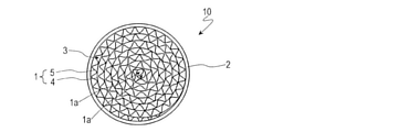
- the exhaust gas purification device 10 according to the embodiment of the present invention will be described with reference to FIG. As shown in FIG. 1, the exhaust gas purifying device 10 has a metal honeycomb structure 1 and an outer cylinder 2.
- the metal honeycomb structure 1 is made of metal (for example, made of stainless steel).
- the metal honeycomb structure 1 includes a plurality of cells 3.
- the average area of the plurality of cells 3 is, for example, 1.0 mm 2 to 2.5 mm 2 .
- the outer cylinder 2 accommodates the metal honeycomb structure 1.
- the outer cylinder 2 has a cylindrical shape.
- the outer cylinder 2 is made of metal (for example, made of stainless steel).
- the metal honeycomb structure 1 has a flat foil 4 and a corrugated foil 5 that are laminated and wound, and a pair of center holes 1a located at the center of the metal honeycomb structure 1.
- the pair of central holes 1a are adjacent to each other and each penetrate the metal honeycomb structure 1.
- a catalyst layer containing a three-way catalyst is provided on the surface of the metal honeycomb structure 1 (that is, the surfaces of the flat foil 4 and the corrugated foil 5).
- the pair of central holes 1a are formed so that the area thereof is within a predetermined range with respect to the average area of the plurality of cells 3. Specifically, the area of each of the pair of central holes 1a is 170% or less of the average area of the plurality of cells 3.
- the "area" of the central hole 1a referred to here is the area when the central hole 1a is viewed from the central axis direction.
- the average area of the cell 3 is also an arithmetic mean value of the area when the cell 3 is viewed from the central axis direction of the central hole 1a.
- the area of the central hole of the metal honeycomb structure was considerably larger than the average area of the cells.
- the area of the central hole is generally 450% or more of the average area of the cell. That is, the difference between the area of the central hole and the average area of the cells is relatively large. Therefore, the gas passing through the central hole may be discharged in a state where the purification rate is lower than that of the gas passing through the cell.
- the purification performance is deteriorated due to the fact that the central hole is larger than that of the cell.
- the area of the central hole 1a of the metal honeycomb structure 1 is 170% or less of the average area of the plurality of cells 3 of the metal honeycomb structure 1. That is, the difference between the area of the central hole 1a and the average area of the cell 3 is relatively small. Therefore, the deterioration of the purification performance due to the central hole 1a of the metal honeycomb structure 1 is suppressed.
- the area of the central hole 1a is preferably 120% or less of the average area of the plurality of cells 3.
- Each of the flat foil 4 and the corrugated foil 5 may have a plurality of openings.
- the surface area of the metal honeycomb structure 1 increases, so that the purification performance can be further improved.
- the embodiment of the present invention has great significance when it is used when the cell density is relatively high, and specifically, when it is used when it is 300 cpsi or more. Further, the embodiment of the present invention is more effective as the outer diameter of the exhaust gas purification device 10 is smaller.
- the purification performance of the exhaust gas purification device 10 having the metal honeycomb structure 1 can be suitably improved.
- the exhaust gas purification device 10 according to the embodiment of the present invention can be manufactured, for example, as follows.
- a flat foil 4 as shown in FIG. 2A and a corrugated foil 5 as shown in FIG. 2B are prepared.
- the flat foil 4 and the corrugated foil 5 are each made of a metal material (for example, stainless steel).
- the corrugated foil 5 can be obtained by, for example, corrugating a metal foil.
- the thickness of the flat foil 4 and the corrugated foil 5 is, for example, 30 ⁇ m or more and 50 ⁇ m or less.
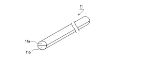
- the winding shaft 11 is prepared.
- the winding shaft 11 is made of a metal material and has a substantially cylindrical shape. From the viewpoint of ensuring the rigidity required for forming the metal honeycomb structure 1, the diameter of the winding shaft 11 is, for example, 5 mm or more.
- the winding shaft 11 is composed of a first member 11a and a second member 11b. The first member 11a and the second member 11b are each semi-cylindrical.
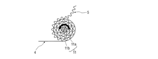
- the flat foil 4 and the corrugated foil 5 are laminated and wound around the winding shaft 11 to form the metal honeycomb structure 1.
- the winding shaft 11 is rotated with a part of the flat foil 4 and the corrugated foil 5 sandwiched between the first member 11a and the second member 11b of the winding shaft 11. Therefore, a pair of center holes 1a corresponding to the first member 11a and the second member 11b of the winding shaft 11 are formed in the center of the metal honeycomb structure 1.
- the flat foil 4 and the corrugated foil 5 are joined by, for example, brazing.
- the metal honeycomb structure 1 is housed in the outer cylinder 2.
- the metal honeycomb structure 1 is joined to the outer cylinder 2 by, for example, brazing.
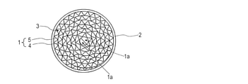
- the area of the central hole 1a located at the center of the metal honeycomb structure 1 is reduced.
- a pair of rod-shaped members 12 are inserted into the pair of center holes 1a.
- Each of the pair of rod-shaped members 12 is a pin thinner than the first member 11a and the second member 11b of the winding shaft 11, for example, having a diameter of about 1 mm.
- the foil separating the pair of central holes 1a is sandwiched between the pair of rod-shaped members 12.
- the metal honeycomb structure 1 is rotated with respect to the pair of rod-shaped members 12. As a result, the vicinity of the central hole 1a of the metal honeycomb structure 1 can be wound, so that the area of the central hole 1a can be reduced.
- a catalyst layer is formed on the surface of the metal honeycomb structure 1.
- at least one noble metal selected from the group consisting of Pt, Pd, Rh, Ir, Ru, Au, Ag and Os, heat-resistant alumina, ceria-zirconia composite oxide, and binder are used.
- a slurry consisting of a viscosity modifier and water is used. Such a slurry is applied directly onto the surface of the metal honeycomb structure 1 and then dried and fired.
- a slurry having the same composition as that of the above-mentioned slurry or having a different composition ratio is applied onto the fired product, and then dried and fired to form at least one catalyst layer.
- a step of reducing the area of the central hole 1a of the metal honeycomb structure 1 is performed, so that the area of the central hole 1a and the plurality of cells are performed.
- the difference from the average area of 3 can be reduced. Therefore, in the exhaust gas purification device 10 manufactured by the above-mentioned manufacturing method, it is possible to suppress the deterioration of the purification performance due to the central hole 1a of the metal honeycomb structure 1.
- the metal honeycomb structure 1 is rotated with respect to the pair of rod-shaped members 12. It can be done easily.
- the step of reducing the area of the central hole 1a is preferably performed so that the area of the central hole 1a is 170% or less of the average area of the plurality of cells 3. , 120% or less is more preferable.
- the area of the central hole 1a may be smaller than the average area of the cell 3.
- the area of the central hole 1a is preferably 90% or more of the average area of the cell 3.
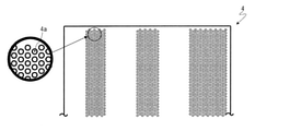
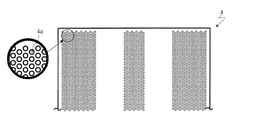
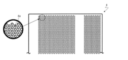
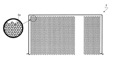
- the prepared flat foil 4 may have a plurality of openings 4a as shown in FIGS. 6A, 6B, 7A, 7B and 7C.
- the opening 4a is, for example, substantially circular, but is not limited thereto.
- 6A, 6B, 7A and 7B illustrate a configuration in which the opening 4a is formed only in a part of the flat foil 4.
- FIG. 7C illustrates a configuration in which an opening 4a is formed on almost the entire surface of the flat foil 4.
- the diameter of the opening is, for example, about 0.9 mm.
- the aperture ratio (ratio of the area occupied by the openings in the foil) is, for example, 18% to 36%. In the configurations exemplified in FIGS. 6A, 6B, 7A, 7B and 7C, the aperture ratios are 18%, 22%, 27%, 31% and 36%, respectively.
- the prepared corrugated foil 5 may have a plurality of openings.
- the opening is, for example, substantially circular, but is not limited thereto.
- an opening may be formed on almost the entire surface of the corrugated foil 5, or an opening may be formed only on a part of the corrugated foil 5.
- the area of the central hole is 7.2 mm 2, which is 600% of the average area of the cells.
- the area of the central hole is 1.2 mm 2, which is 100% of the average area of the cell.
- the area of the central hole is 1.8 mm 2, which is 150% of the average area of the cell.
- the flat foil and the corrugated foil do not have an opening.
- the flat foil and the corrugated foil have an opening, and the aperture ratio (the ratio of the area occupied by the opening in the foil) is 21%.
- FIG. 8 shows the measurement results of NOx emissions, CO emissions and THC emissions for Examples 1 to 4 and Comparative Examples 1 and 2.
- FIG. 8 shows relative values in which NOx emission amount, CO emission amount, and THC emission amount of Comparative Example 1 are each set to 1.
- Examples 1 and 2 have smaller NOx emissions, CO emissions, and THC emissions than Comparative Example 1.
- Examples 3 and 4 have smaller NOx emissions, CO emissions, and THC emissions than Comparative Example 2. From these facts, it was confirmed that the purification performance was improved by reducing the area of the central hole (that is, reducing the difference between the area of the central hole and the average area of the cells).
- Example 1 was superior in purification performance to Example 2, and Example 3 was superior in purification performance to Example 4. From these facts, it was confirmed that the smaller the area of the central hole (that is, the smaller the difference between the area of the central hole and the average area of the cell), the better the purification performance.
- the area of the central hole 1a is 170% or less of the average area of the cell, the deterioration of the purification performance due to the central hole is suppressed. Further, from the viewpoint of improving the purification performance, it is preferable that the area of the central hole 1a is 120% or less of the average area of the cells. Further, since the flat foil 4 and the corrugated foil 5 each have a plurality of openings, the purification performance is further improved. Since forming a plurality of openings in the flat foil 4 and the corrugated foil 5 entails an increase in manufacturing cost, the configuration in which the flat foil 4 and the corrugated foil 5 do not have openings is advantageous in terms of manufacturing cost. It can be said that there is.
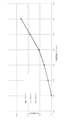
- FIG. 9A shows the results of measuring the pressure drop values for Examples 1, 2 and Comparative Example 1
- FIG. 9B shows the results of measuring the pressure drop values for Examples 3, 4 and Comparative Example 2.
- 9A and 9B show relative values (pressure loss ratio) with the pressure loss value as 1 when the volume flow rate is 0.5 m 3 / min.
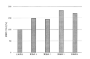
- FIG. 10 shows the results of the heating / cooling vibration test for Examples 1 to 4 and Comparative Example 1.
- FIG. 10 shows a relative value (test cycle ratio) with the number of test cycles of Comparative Example 1 as 100%.
- the purification performance of the exhaust gas purification device 10 having the metal honeycomb structure 1 can be suitably improved.
- the exhaust gas purification device 10 according to the embodiment of the present invention is suitably used for various saddle-mounted vehicles.
- FIG. 11 shows an example of a motorcycle 100 provided with an exhaust gas purification device 10 according to an embodiment of the present invention.
- the motorcycle 100 shown in FIG. 11 includes an engine (internal combustion engine) 21, an exhaust pipe 22, and a silencer 23.
- the exhaust pipe 22 is connected to the exhaust port of the engine 21.
- the silencer 23 is connected to the exhaust pipe 22.
- An exhaust gas purification device 10 (not shown in FIG. 11) is arranged in the exhaust pipe 22 and the silencer 23.
- a secondary air injection device (not shown) for introducing secondary air is also arranged in the exhaust pipe 22.
- the saddle-mounted vehicle provided with the exhaust gas purification device 10 is not limited to the motorcycle 100.
- the saddle-mounted vehicle may be, for example, an ATV (All Terrain Vehicle), a snowmobile, a tricycle, or the like.
- the exhaust gas purification device 10 according to the embodiment of the present invention can be suitably used for vehicles other than saddle-mounted vehicles, and can be suitably used for, for example, generators and agricultural machinery.
- the exhaust gas purification device 10 is an exhaust gas purification device 10 having a metal metal honeycomb structure 1 including a plurality of cells 3, and the metal honeycomb structure 1 is laminated. It has a flat foil 4 and a corrugated foil 5 which have been wound and wound, and a central hole 1a which is located at the center of the metal honeycomb structure 1 and penetrates the metal honeycomb structure 1, and the area of the central hole 1a is , 170% or less of the average area of the plurality of cells 3.
- the area of the central hole 1a of the metal honeycomb structure 1 is 170% or less of the average area of the plurality of cells 3 of the metal honeycomb structure 1. That is, the difference between the area of the central hole 1a and the average area of the cell 3 is relatively small. Therefore, the deterioration of the purification performance due to the central hole 1a of the metal honeycomb structure 1 is suppressed.
- the area of the central hole 1a is 120% or less of the average area of the plurality of cells 3.
- the area of the central hole 1a is preferably 120% or less of the average area of the plurality of cells 3.
- each of the flat foil 4 and the corrugated foil 5 has a plurality of openings 4a.
- each of the flat foil 4 and the corrugated foil 5 has a plurality of openings 4a, the chance of contact between the exhaust gas and the noble metal in the catalyst layer increases, so that the purification performance can be improved.
- the cell density of the plurality of cells 3 is 300 cpsi or more.
- the embodiment of the present invention has great significance when it is used when the cell density is relatively high, specifically, when it is 300 cpsi or more. Further, the embodiment of the present invention is more effective as the outer diameter of the exhaust gas purification device 10 is smaller.
- the saddle-mounted vehicle according to the embodiment of the present invention includes an exhaust gas purification device 10 having any of the above configurations.
- the exhaust gas purification device 10 according to the embodiment of the present invention is suitably used for various saddle-mounted vehicles.
- the method for manufacturing the exhaust gas purification device 10 is a method for manufacturing the exhaust gas purification device 10 having a metal honeycomb structure 1 made of a metal including a plurality of cells 3, and comprises flat foil 4 and corrugated foil 5.
- the step (a) of forming the metal honeycomb structure 1 by laminating and winding around the winding shaft 11 and the step (a) the center hole 1a located at the center of the metal honeycomb structure 1
- the step (b) of reducing the area of the above is included.
- the metal honeycomb structure 1 has a pair of central holes 1a, and in the step (b), after inserting a pair of rod-shaped members 12 into the pair of central holes 1a, the pair of rod-shaped members This is done by rotating the metal honeycomb structure 1 with respect to the member 12.
- the metal honeycomb structure 1 is rotated with respect to the pair of rod-shaped members 12a. It can be done easily.
- the step (b) is performed so that the area of the central hole 1a is 170% or less of the average area of the plurality of cells 3.
- the step (b) for reducing the area of the central hole 1a is performed so that the area of the central hole 1a is 170% or less of the average area of the plurality of cells 3, the deterioration of the purification performance can be sufficiently suppressed.
- the purification performance of the exhaust gas purification device having the metal honeycomb structure can be suitably improved.
- the exhaust gas purification device according to the embodiment of the present invention is suitably used for various saddle-type vehicles, generators, agricultural machinery and the like.
Landscapes
- Chemical & Material Sciences (AREA)
- Engineering & Computer Science (AREA)
- Chemical Kinetics & Catalysis (AREA)
- Materials Engineering (AREA)
- Organic Chemistry (AREA)
- Combustion & Propulsion (AREA)
- Health & Medical Sciences (AREA)
- Environmental & Geological Engineering (AREA)
- Biomedical Technology (AREA)
- Analytical Chemistry (AREA)
- General Chemical & Material Sciences (AREA)
- Oil, Petroleum & Natural Gas (AREA)
- Toxicology (AREA)
- Mechanical Engineering (AREA)
- General Engineering & Computer Science (AREA)
- Catalysts (AREA)
- Exhaust Gas Treatment By Means Of Catalyst (AREA)
- Exhaust Gas After Treatment (AREA)
Abstract
Un dispositif de purification de gaz d'échappement (10) comprend une structure en nid d'abeilles métallique (1) qui est constituée de métal et contient une pluralité de cellules (3). La structure en nid d'abeilles métallique comprend : une feuille plate (4) et une feuille ondulée (5) qui sont stratifiées et enroulées ; et des trous centraux (1a) qui sont positionnés au centre de la structure en nid d'abeilles métallique et pénètrent dans la structure en nid d'abeilles métallique. La surface des trous centraux n'est pas supérieure à 170 % de la surface moyenne de la pluralité de cellules.
Applications Claiming Priority (2)
| Application Number | Priority Date | Filing Date | Title |
|---|---|---|---|
| JP2020-125557 | 2020-07-22 | ||
| JP2020125557A JP2023123886A (ja) | 2020-07-22 | 2020-07-22 | 排ガス浄化装置、鞍乗型車両および排ガス浄化装置の製造方法 |
Publications (1)
| Publication Number | Publication Date |
|---|---|
| WO2022019011A1 true WO2022019011A1 (fr) | 2022-01-27 |
Family
ID=79729447
Family Applications (1)
| Application Number | Title | Priority Date | Filing Date |
|---|---|---|---|
| PCT/JP2021/022917 Ceased WO2022019011A1 (fr) | 2020-07-22 | 2021-06-16 | Dispositif de purification de gaz d'échappement, véhicule de type à selle et procédé de fabrication de dispositif de purification de gaz d'échappement |
Country Status (2)
| Country | Link |
|---|---|
| JP (1) | JP2023123886A (fr) |
| WO (1) | WO2022019011A1 (fr) |
Citations (3)
| Publication number | Priority date | Publication date | Assignee | Title |
|---|---|---|---|---|
| JPH07328779A (ja) * | 1994-06-06 | 1995-12-19 | Nippon Steel Corp | メタル担体の製造方法 |
| JP2018150811A (ja) * | 2015-07-31 | 2018-09-27 | ヤマハ発動機株式会社 | 排ガス浄化装置及び鞍乗型車両 |
| WO2019031080A1 (fr) * | 2017-08-08 | 2019-02-14 | 株式会社キャタラー | Substrat métallique de purification de gaz d'échappement et dispositif depurification de gaz d'échappement l'utilisant |
-
2020
- 2020-07-22 JP JP2020125557A patent/JP2023123886A/ja active Pending
-
2021
- 2021-06-16 WO PCT/JP2021/022917 patent/WO2022019011A1/fr not_active Ceased
Patent Citations (3)
| Publication number | Priority date | Publication date | Assignee | Title |
|---|---|---|---|---|
| JPH07328779A (ja) * | 1994-06-06 | 1995-12-19 | Nippon Steel Corp | メタル担体の製造方法 |
| JP2018150811A (ja) * | 2015-07-31 | 2018-09-27 | ヤマハ発動機株式会社 | 排ガス浄化装置及び鞍乗型車両 |
| WO2019031080A1 (fr) * | 2017-08-08 | 2019-02-14 | 株式会社キャタラー | Substrat métallique de purification de gaz d'échappement et dispositif depurification de gaz d'échappement l'utilisant |
Also Published As
| Publication number | Publication date |
|---|---|
| JP2023123886A (ja) | 2023-09-06 |
Similar Documents
| Publication | Publication Date | Title |
|---|---|---|
| JP6505336B1 (ja) | 排ガス浄化用のメタル基材及びそれを用いた排ガス浄化装置 | |
| US5474745A (en) | Catalytic converter for purifying exhaust gas | |
| CN1395508A (zh) | 金属催化剂载体 | |
| CN104005821B (zh) | 废气用催化装置 | |
| US3998599A (en) | System for catalytic reduction of NOx emanating from an internal combustion engine | |
| US7375056B2 (en) | Method of making a NOx adsorber catalyst | |
| CN101128655B (zh) | 具有带裂口的端面侧的蜂窝体 | |
| JP2012520974A (ja) | 排ガスを処理するための一体型排気処理ユニット | |
| JP7335468B1 (ja) | 排気ガスの浄化に用いられる触媒担持用基材 | |
| WO2022019011A1 (fr) | Dispositif de purification de gaz d'échappement, véhicule de type à selle et procédé de fabrication de dispositif de purification de gaz d'échappement | |
| US8137637B2 (en) | Particulate filter and method of making | |
| US10280822B2 (en) | Exhaust gas purifying apparatus | |
| EP4043102A1 (fr) | Unité en nid d'abeilles utilisée pour la purification de gaz d'échappement, et procédé de fabrication d'une unité en nid d'abeilles | |
| CN113382802A (zh) | 排气净化用的金属基材和使用该金属基材的排气净化装置 | |
| RU2721686C1 (ru) | Каталитические субстраты | |
| US10753247B2 (en) | Bi-metallic oxidation catalyst materials and appurtenant devices and systems | |
| WO2025062661A1 (fr) | Support en nid-d'abeilles et procédé de purification de gaz d'échappement | |
| EP3179065B1 (fr) | Convertisseur catalytique | |
| JP2026052871A (ja) | ハニカムユニット及び触媒コンバータ | |
| CN121866109A (zh) | 用于废气净化的蜂窝单元及催化转换器 | |
| JP2025024959A (ja) | ハニカムユニットおよび触媒コンバータ | |
| JP4217999B2 (ja) | 排気ガス浄化装置 | |
| JPH078803A (ja) | 金属製触媒担体 | |
| WO2025187094A1 (fr) | Système catalytique de purification de gaz d'échappement | |
| JPS62273049A (ja) | メタル担体触媒のメタル担体 |
Legal Events
| Date | Code | Title | Description |
|---|---|---|---|
| 121 | Ep: the epo has been informed by wipo that ep was designated in this application |
Ref document number: 21845334 Country of ref document: EP Kind code of ref document: A1 |
|
| NENP | Non-entry into the national phase |
Ref country code: DE |
|
| 122 | Ep: pct application non-entry in european phase |
Ref document number: 21845334 Country of ref document: EP Kind code of ref document: A1 |
|
| NENP | Non-entry into the national phase |
Ref country code: JP |