WO2022019059A1 - 摺動部材 - Google Patents
摺動部材 Download PDFInfo
- Publication number
- WO2022019059A1 WO2022019059A1 PCT/JP2021/024335 JP2021024335W WO2022019059A1 WO 2022019059 A1 WO2022019059 A1 WO 2022019059A1 JP 2021024335 W JP2021024335 W JP 2021024335W WO 2022019059 A1 WO2022019059 A1 WO 2022019059A1
- Authority
- WO
- WIPO (PCT)
- Prior art keywords
- overlay
- oxide
- sliding member
- lining
- intermediate layer
- Prior art date
- Legal status (The legal status is an assumption and is not a legal conclusion. Google has not performed a legal analysis and makes no representation as to the accuracy of the status listed.)
- Ceased
Links
Images

Classifications
-
- C—CHEMISTRY; METALLURGY
- C23—COATING METALLIC MATERIAL; COATING MATERIAL WITH METALLIC MATERIAL; CHEMICAL SURFACE TREATMENT; DIFFUSION TREATMENT OF METALLIC MATERIAL; COATING BY VACUUM EVAPORATION, BY SPUTTERING, BY ION IMPLANTATION OR BY CHEMICAL VAPOUR DEPOSITION, IN GENERAL; INHIBITING CORROSION OF METALLIC MATERIAL OR INCRUSTATION IN GENERAL
- C23C—COATING METALLIC MATERIAL; COATING MATERIAL WITH METALLIC MATERIAL; SURFACE TREATMENT OF METALLIC MATERIAL BY DIFFUSION INTO THE SURFACE, BY CHEMICAL CONVERSION OR SUBSTITUTION; COATING BY VACUUM EVAPORATION, BY SPUTTERING, BY ION IMPLANTATION OR BY CHEMICAL VAPOUR DEPOSITION, IN GENERAL
- C23C28/00—Coating for obtaining at least two superposed coatings either by methods not provided for in a single one of groups C23C2/00 - C23C26/00 or by combinations of methods provided for in subclasses C23C and C25C or C25D
- C23C28/02—Coating for obtaining at least two superposed coatings either by methods not provided for in a single one of groups C23C2/00 - C23C26/00 or by combinations of methods provided for in subclasses C23C and C25C or C25D only coatings only including layers of metallic material
- C23C28/023—Coating for obtaining at least two superposed coatings either by methods not provided for in a single one of groups C23C2/00 - C23C26/00 or by combinations of methods provided for in subclasses C23C and C25C or C25D only coatings only including layers of metallic material only coatings of metal elements only
-
- C—CHEMISTRY; METALLURGY
- C22—METALLURGY; FERROUS OR NON-FERROUS ALLOYS; TREATMENT OF ALLOYS OR NON-FERROUS METALS
- C22C—ALLOYS
- C22C12/00—Alloys based on antimony or bismuth
-
- C—CHEMISTRY; METALLURGY
- C23—COATING METALLIC MATERIAL; COATING MATERIAL WITH METALLIC MATERIAL; CHEMICAL SURFACE TREATMENT; DIFFUSION TREATMENT OF METALLIC MATERIAL; COATING BY VACUUM EVAPORATION, BY SPUTTERING, BY ION IMPLANTATION OR BY CHEMICAL VAPOUR DEPOSITION, IN GENERAL; INHIBITING CORROSION OF METALLIC MATERIAL OR INCRUSTATION IN GENERAL
- C23C—COATING METALLIC MATERIAL; COATING MATERIAL WITH METALLIC MATERIAL; SURFACE TREATMENT OF METALLIC MATERIAL BY DIFFUSION INTO THE SURFACE, BY CHEMICAL CONVERSION OR SUBSTITUTION; COATING BY VACUUM EVAPORATION, BY SPUTTERING, BY ION IMPLANTATION OR BY CHEMICAL VAPOUR DEPOSITION, IN GENERAL
- C23C28/00—Coating for obtaining at least two superposed coatings either by methods not provided for in a single one of groups C23C2/00 - C23C26/00 or by combinations of methods provided for in subclasses C23C and C25C or C25D
- C23C28/02—Coating for obtaining at least two superposed coatings either by methods not provided for in a single one of groups C23C2/00 - C23C26/00 or by combinations of methods provided for in subclasses C23C and C25C or C25D only coatings only including layers of metallic material
- C23C28/028—Including graded layers in composition or in physical properties, e.g. density, porosity, grain size
-
- C—CHEMISTRY; METALLURGY
- C23—COATING METALLIC MATERIAL; COATING MATERIAL WITH METALLIC MATERIAL; CHEMICAL SURFACE TREATMENT; DIFFUSION TREATMENT OF METALLIC MATERIAL; COATING BY VACUUM EVAPORATION, BY SPUTTERING, BY ION IMPLANTATION OR BY CHEMICAL VAPOUR DEPOSITION, IN GENERAL; INHIBITING CORROSION OF METALLIC MATERIAL OR INCRUSTATION IN GENERAL
- C23C—COATING METALLIC MATERIAL; COATING MATERIAL WITH METALLIC MATERIAL; SURFACE TREATMENT OF METALLIC MATERIAL BY DIFFUSION INTO THE SURFACE, BY CHEMICAL CONVERSION OR SUBSTITUTION; COATING BY VACUUM EVAPORATION, BY SPUTTERING, BY ION IMPLANTATION OR BY CHEMICAL VAPOUR DEPOSITION, IN GENERAL
- C23C30/00—Coating with metallic material characterised only by the composition of the metallic material, i.e. not characterised by the coating process
-
- C—CHEMISTRY; METALLURGY
- C23—COATING METALLIC MATERIAL; COATING MATERIAL WITH METALLIC MATERIAL; CHEMICAL SURFACE TREATMENT; DIFFUSION TREATMENT OF METALLIC MATERIAL; COATING BY VACUUM EVAPORATION, BY SPUTTERING, BY ION IMPLANTATION OR BY CHEMICAL VAPOUR DEPOSITION, IN GENERAL; INHIBITING CORROSION OF METALLIC MATERIAL OR INCRUSTATION IN GENERAL
- C23C—COATING METALLIC MATERIAL; COATING MATERIAL WITH METALLIC MATERIAL; SURFACE TREATMENT OF METALLIC MATERIAL BY DIFFUSION INTO THE SURFACE, BY CHEMICAL CONVERSION OR SUBSTITUTION; COATING BY VACUUM EVAPORATION, BY SPUTTERING, BY ION IMPLANTATION OR BY CHEMICAL VAPOUR DEPOSITION, IN GENERAL
- C23C6/00—Coating by casting molten material on the substrate
-
- C—CHEMISTRY; METALLURGY
- C25—ELECTROLYTIC OR ELECTROPHORETIC PROCESSES; APPARATUS THEREFOR
- C25D—PROCESSES FOR THE ELECTROLYTIC OR ELECTROPHORETIC PRODUCTION OF COATINGS; ELECTROFORMING; APPARATUS THEREFOR
- C25D5/00—Electroplating characterised by the process; Pretreatment or after-treatment of workpieces
- C25D5/48—After-treatment of electroplated surfaces
- C25D5/50—After-treatment of electroplated surfaces by heat-treatment
-
- C—CHEMISTRY; METALLURGY
- C25—ELECTROLYTIC OR ELECTROPHORETIC PROCESSES; APPARATUS THEREFOR
- C25D—PROCESSES FOR THE ELECTROLYTIC OR ELECTROPHORETIC PRODUCTION OF COATINGS; ELECTROFORMING; APPARATUS THEREFOR
- C25D7/00—Electroplating characterised by the article coated
-
- F—MECHANICAL ENGINEERING; LIGHTING; HEATING; WEAPONS; BLASTING
- F16—ENGINEERING ELEMENTS AND UNITS; GENERAL MEASURES FOR PRODUCING AND MAINTAINING EFFECTIVE FUNCTIONING OF MACHINES OR INSTALLATIONS; THERMAL INSULATION IN GENERAL
- F16C—SHAFTS; FLEXIBLE SHAFTS; ELEMENTS OR CRANKSHAFT MECHANISMS; ROTARY BODIES OTHER THAN GEARING ELEMENTS; BEARINGS
- F16C17/00—Sliding-contact bearings for exclusively rotary movement
- F16C17/02—Sliding-contact bearings for exclusively rotary movement for radial load only
-
- F—MECHANICAL ENGINEERING; LIGHTING; HEATING; WEAPONS; BLASTING
- F16—ENGINEERING ELEMENTS AND UNITS; GENERAL MEASURES FOR PRODUCING AND MAINTAINING EFFECTIVE FUNCTIONING OF MACHINES OR INSTALLATIONS; THERMAL INSULATION IN GENERAL
- F16C—SHAFTS; FLEXIBLE SHAFTS; ELEMENTS OR CRANKSHAFT MECHANISMS; ROTARY BODIES OTHER THAN GEARING ELEMENTS; BEARINGS
- F16C17/00—Sliding-contact bearings for exclusively rotary movement
- F16C17/02—Sliding-contact bearings for exclusively rotary movement for radial load only
- F16C17/022—Sliding-contact bearings for exclusively rotary movement for radial load only with a pair of essentially semicircular bearing sleeves
-
- F—MECHANICAL ENGINEERING; LIGHTING; HEATING; WEAPONS; BLASTING
- F16—ENGINEERING ELEMENTS AND UNITS; GENERAL MEASURES FOR PRODUCING AND MAINTAINING EFFECTIVE FUNCTIONING OF MACHINES OR INSTALLATIONS; THERMAL INSULATION IN GENERAL
- F16C—SHAFTS; FLEXIBLE SHAFTS; ELEMENTS OR CRANKSHAFT MECHANISMS; ROTARY BODIES OTHER THAN GEARING ELEMENTS; BEARINGS
- F16C17/00—Sliding-contact bearings for exclusively rotary movement
- F16C17/04—Sliding-contact bearings for exclusively rotary movement for axial load only
-
- F—MECHANICAL ENGINEERING; LIGHTING; HEATING; WEAPONS; BLASTING
- F16—ENGINEERING ELEMENTS AND UNITS; GENERAL MEASURES FOR PRODUCING AND MAINTAINING EFFECTIVE FUNCTIONING OF MACHINES OR INSTALLATIONS; THERMAL INSULATION IN GENERAL
- F16C—SHAFTS; FLEXIBLE SHAFTS; ELEMENTS OR CRANKSHAFT MECHANISMS; ROTARY BODIES OTHER THAN GEARING ELEMENTS; BEARINGS
- F16C33/00—Parts of bearings; Special methods for making bearings or parts thereof
- F16C33/02—Parts of sliding-contact bearings
- F16C33/04—Brasses; Bushes; Linings
- F16C33/06—Sliding surface mainly made of metal
- F16C33/12—Structural composition; Use of special materials or surface treatments, e.g. for rust-proofing
- F16C33/121—Use of special materials
-
- F—MECHANICAL ENGINEERING; LIGHTING; HEATING; WEAPONS; BLASTING
- F16—ENGINEERING ELEMENTS AND UNITS; GENERAL MEASURES FOR PRODUCING AND MAINTAINING EFFECTIVE FUNCTIONING OF MACHINES OR INSTALLATIONS; THERMAL INSULATION IN GENERAL
- F16C—SHAFTS; FLEXIBLE SHAFTS; ELEMENTS OR CRANKSHAFT MECHANISMS; ROTARY BODIES OTHER THAN GEARING ELEMENTS; BEARINGS
- F16C33/00—Parts of bearings; Special methods for making bearings or parts thereof
- F16C33/02—Parts of sliding-contact bearings
- F16C33/04—Brasses; Bushes; Linings
- F16C33/06—Sliding surface mainly made of metal
- F16C33/12—Structural composition; Use of special materials or surface treatments, e.g. for rust-proofing
- F16C33/122—Multilayer structures of sleeves, washers or liners
- F16C33/124—Details of overlays
-
- B—PERFORMING OPERATIONS; TRANSPORTING
- B22—CASTING; POWDER METALLURGY
- B22F—WORKING METALLIC POWDER; MANUFACTURE OF ARTICLES FROM METALLIC POWDER; MAKING METALLIC POWDER; APPARATUS OR DEVICES SPECIALLY ADAPTED FOR METALLIC POWDER
- B22F7/00—Manufacture of composite layers, workpieces, or articles, comprising metallic powder, by sintering the powder, with or without compacting wherein at least one part is obtained by sintering or compression
- B22F7/02—Manufacture of composite layers, workpieces, or articles, comprising metallic powder, by sintering the powder, with or without compacting wherein at least one part is obtained by sintering or compression of composite layers
- B22F7/04—Manufacture of composite layers, workpieces, or articles, comprising metallic powder, by sintering the powder, with or without compacting wherein at least one part is obtained by sintering or compression of composite layers with one or more layers not made from powder, e.g. made from solid metal
-
- C—CHEMISTRY; METALLURGY
- C25—ELECTROLYTIC OR ELECTROPHORETIC PROCESSES; APPARATUS THEREFOR
- C25D—PROCESSES FOR THE ELECTROLYTIC OR ELECTROPHORETIC PRODUCTION OF COATINGS; ELECTROFORMING; APPARATUS THEREFOR
- C25D3/00—Electroplating: Baths therefor
- C25D3/02—Electroplating: Baths therefor from solutions
- C25D3/56—Electroplating: Baths therefor from solutions of alloys
-
- C—CHEMISTRY; METALLURGY
- C25—ELECTROLYTIC OR ELECTROPHORETIC PROCESSES; APPARATUS THEREFOR
- C25D—PROCESSES FOR THE ELECTROLYTIC OR ELECTROPHORETIC PRODUCTION OF COATINGS; ELECTROFORMING; APPARATUS THEREFOR
- C25D5/00—Electroplating characterised by the process; Pretreatment or after-treatment of workpieces
- C25D5/10—Electroplating with more than one layer of the same or of different metals
-
- F—MECHANICAL ENGINEERING; LIGHTING; HEATING; WEAPONS; BLASTING
- F16—ENGINEERING ELEMENTS AND UNITS; GENERAL MEASURES FOR PRODUCING AND MAINTAINING EFFECTIVE FUNCTIONING OF MACHINES OR INSTALLATIONS; THERMAL INSULATION IN GENERAL
- F16C—SHAFTS; FLEXIBLE SHAFTS; ELEMENTS OR CRANKSHAFT MECHANISMS; ROTARY BODIES OTHER THAN GEARING ELEMENTS; BEARINGS
- F16C2204/00—Metallic materials; Alloys
- F16C2204/30—Alloys based on one of tin, lead, antimony, bismuth, indium, e.g. materials for providing sliding surfaces
-
- F—MECHANICAL ENGINEERING; LIGHTING; HEATING; WEAPONS; BLASTING
- F16—ENGINEERING ELEMENTS AND UNITS; GENERAL MEASURES FOR PRODUCING AND MAINTAINING EFFECTIVE FUNCTIONING OF MACHINES OR INSTALLATIONS; THERMAL INSULATION IN GENERAL
- F16C—SHAFTS; FLEXIBLE SHAFTS; ELEMENTS OR CRANKSHAFT MECHANISMS; ROTARY BODIES OTHER THAN GEARING ELEMENTS; BEARINGS
- F16C2204/00—Metallic materials; Alloys
- F16C2204/30—Alloys based on one of tin, lead, antimony, bismuth, indium, e.g. materials for providing sliding surfaces
- F16C2204/36—Alloys based on bismuth
-
- F—MECHANICAL ENGINEERING; LIGHTING; HEATING; WEAPONS; BLASTING
- F16—ENGINEERING ELEMENTS AND UNITS; GENERAL MEASURES FOR PRODUCING AND MAINTAINING EFFECTIVE FUNCTIONING OF MACHINES OR INSTALLATIONS; THERMAL INSULATION IN GENERAL
- F16C—SHAFTS; FLEXIBLE SHAFTS; ELEMENTS OR CRANKSHAFT MECHANISMS; ROTARY BODIES OTHER THAN GEARING ELEMENTS; BEARINGS
- F16C2240/00—Specified values or numerical ranges of parameters; Relations between them
- F16C2240/94—Volume
-
- F—MECHANICAL ENGINEERING; LIGHTING; HEATING; WEAPONS; BLASTING
- F16—ENGINEERING ELEMENTS AND UNITS; GENERAL MEASURES FOR PRODUCING AND MAINTAINING EFFECTIVE FUNCTIONING OF MACHINES OR INSTALLATIONS; THERMAL INSULATION IN GENERAL
- F16C—SHAFTS; FLEXIBLE SHAFTS; ELEMENTS OR CRANKSHAFT MECHANISMS; ROTARY BODIES OTHER THAN GEARING ELEMENTS; BEARINGS
- F16C2326/00—Articles relating to transporting
- F16C2326/01—Parts of vehicles in general
-
- F—MECHANICAL ENGINEERING; LIGHTING; HEATING; WEAPONS; BLASTING
- F16—ENGINEERING ELEMENTS AND UNITS; GENERAL MEASURES FOR PRODUCING AND MAINTAINING EFFECTIVE FUNCTIONING OF MACHINES OR INSTALLATIONS; THERMAL INSULATION IN GENERAL
- F16C—SHAFTS; FLEXIBLE SHAFTS; ELEMENTS OR CRANKSHAFT MECHANISMS; ROTARY BODIES OTHER THAN GEARING ELEMENTS; BEARINGS
- F16C2362/00—Apparatus for lighting or heating
- F16C2362/52—Compressors of refrigerators, e.g. air-conditioners
-
- Y—GENERAL TAGGING OF NEW TECHNOLOGICAL DEVELOPMENTS; GENERAL TAGGING OF CROSS-SECTIONAL TECHNOLOGIES SPANNING OVER SEVERAL SECTIONS OF THE IPC; TECHNICAL SUBJECTS COVERED BY FORMER USPC CROSS-REFERENCE ART COLLECTIONS [XRACs] AND DIGESTS
- Y02—TECHNOLOGIES OR APPLICATIONS FOR MITIGATION OR ADAPTATION AGAINST CLIMATE CHANGE
- Y02T—CLIMATE CHANGE MITIGATION TECHNOLOGIES RELATED TO TRANSPORTATION
- Y02T10/00—Road transport of goods or passengers
- Y02T10/80—Technologies aiming to reduce greenhouse gasses emissions common to all road transportation technologies
- Y02T10/86—Optimisation of rolling resistance, e.g. weight reduction
Definitions
- the present invention relates to a sliding member provided with an overlay of an alloy plating film of Bi and Sb.
- Patent Document 1 discloses a technique for improving seizure resistance by forming bismuth oxide on the surface of an overlay.
- the present invention has been made in view of the above problems, and an object thereof is to improve fatigue resistance.
- the sliding member is a sliding member having an overlay formed by an alloy plating film of Bi and Sb, and Bi-Sb oxide is formed on the surface of the overlay.
- Bi-Sb oxide is more resistant to brittle fracture than bismuth oxide.
- the presence of Bi-Sb oxide on the surface of the overlay prevents the formation and growth of bismuth oxide. Therefore, the Bi-Sb oxide formed on the surface of the overlay can prevent the bismuth oxide from falling off and improve the fatigue resistance of the sliding member.
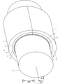
- FIG. 1 is a perspective view of a sliding member 1 according to an embodiment of the present invention.
- the sliding member 1 includes a back metal 10, a lining 11, and an overlay 12.
- the sliding member 1 is a metal member having a semicircular shape obtained by dividing a hollow cylinder into two equal parts in the diameter direction, and has a semicircular arc shape.
- the slide bearing A is formed by combining the two sliding members 1 so as to form a cylinder.
- the slide bearing A bearings a columnar mating shaft 2 (crankshaft of an engine) in a hollow portion formed inside.
- the outer diameter of the mating shaft 2 is formed to be slightly smaller than the inner diameter of the slide bearing A.
- Lubricating oil engine oil
- the sliding member 1 has a structure in which a back metal 10, a lining 11, an intermediate layer 13, and an overlay 12 are laminated in order from the center of curvature. Therefore, the back metal 10 constitutes the outermost layer of the sliding member 1, and the overlay 12 constitutes the innermost layer of the sliding member 1.
- the back metal 10, the lining 11, the intermediate layer 13, and the overlay 12 each have a certain thickness in the circumferential direction.
- the thickness of the back metal 10 is, for example, 1.5 mm
- the thickness of the lining 11 is, for example, 0.2 mm to 0.3 mm
- the thickness of the intermediate layer 13 is, for example, 1.0 to 7.0 ⁇ m
- the overlay 12 is used.
- the thickness of the overlay is, for example, 3 to 20 ⁇ m.
- Twice the radius of the surface of the overlay 12 on the center side of the curvature is, for example, 55 mm.
- the width of the slide bearing A is, for example, 19 mm.
- the inside means the curvature center side of the sliding member 1
- the outside means the side opposite to the curvature center of the sliding member 1.
- the inner surface of the overlay 12 constitutes the sliding surface of the mating shaft 2.
- the back metal 10 is made of steel containing, for example, 0.15% by mass of C, 0.06% by mass of Mn, and the balance is Fe.
- the back metal 10 may be formed of a material capable of supporting the load from the mating shaft 2 via the lining 11 and the overlay 12, and may not necessarily be formed of steel.
- the lining 11 is a layer laminated inside the back metal 10 and constitutes a base layer.
- the lining 11 is made of a Cu alloy.
- the elements contained in the lining 11 are not limited, and examples thereof include examples in which the lining 11 is composed of a Cu—Bi alloy.
- elements other than Cu and Bi may be added.
- Bi, Sn, and Ni each contain 5% by mass, 5% by mass, and 5% by mass, and the balance is Cu.
- the lining 11 can be formed of a Cu alloy containing 3% by mass and 3% by mass of Bi and In, respectively, and the balance is Cu.
- the lining 11 may be an alloy other than the Cu alloy, for example, an Al alloy.
- Various elements are assumed as the elements added to the Al alloy, and examples thereof include Sn, Si, and Mg. More specifically, for example, the lining 11 can be configured by an Al alloy containing 7% by mass and 3% by mass of Sn and Si, respectively, and the balance is Al. Further, the lining 11 can be formed of an Al alloy containing 3% by mass of Mg and the balance being Al.
- unavoidable impurities may be contained.
- the unavoidable impurities in the lining 11 are Mg, Ti, B, Pb, Cr and the like, and impurities and the like mixed in refining or scrap are assumed.
- the content of unavoidable impurities in the lining 11 is, for example, 0.5% by mass or less as a whole.
- the intermediate layer 13 may be omitted or may be provided to use various functions.
- the lining 11 is a Cu alloy
- the amount of Cu diffused from the lining 11 to the overlay 12 is reduced. It is possible to reduce the possibility that the fatigue resistance is lowered.
- the intermediate layer containing Ag as a main component may be, for example, pure Ag, Ag-Sn, or the like. In the latter case, the Sn concentration may be, for example, 20% by mass.
- the intermediate layer 13 may be composed of a plurality of layers.
- a first intermediate layer containing Cu as a main component is formed on the lining 11
- a second intermediate layer containing Ag as a main component is formed between the first intermediate layer and the overlay 12.
- the first intermediate layer may be, for example, a configuration in which it is pure Cu.
- the second intermediate layer may be, for example, pure Ag, Ag-Sn, or the like. In the latter case, the Sn concentration may be, for example, 20% by mass.
- composition of the intermediate layer is not limited to these examples, for example, a first intermediate layer containing Ag as a main component is formed on various linings, and Ag-is formed between the first intermediate layer and the overlay 12.
- the configuration may be such that a second intermediate layer containing Sn as a main component is formed.
- the amount of Cu diffused from the Cu of the first intermediate layer to the overlay 12 can be reduced by the second intermediate layer containing Ag as a main component, and the possibility that the fatigue resistance is lowered is reduced. can do. Further, since the first intermediate layer is formed by Cu, the possibility of delamination between the second intermediate layer and the lining 11 can be reduced.
- the intermediate layer 13 may contain unavoidable impurities. The content of unavoidable impurities in the intermediate layer 13 is, for example, 0.5% by mass or less as a whole.
- the overlay 12 is a layer laminated on the inner surface of the lining 11.
- the overlay 12 is an alloy plating film of Bi and Sb, and a Bi—Sb oxide is formed on the surface thereof.
- the overlay 12 may contain unavoidable impurities.
- the content of unavoidable impurities in the overlay 12 is, for example, 0.5% by mass or less as a whole.
- the sliding member can be formed by the back metal 10 of 5 mm.
- a sliding member can be formed by a back metal 10 having a thickness of 1.5 mm.
- a Bi-Sb oxide is formed on the surface of the overlay 12 according to the present embodiment.
- the overlay 12 is formed by oxidizing the alloy plating film of Bi and Sb.
- an example of a method for manufacturing a sliding member will be described by taking as an example a configuration in which the lining 11 is a Cu alloy containing Sn, Ni, and Bi and the intermediate layer 13 is Ag—Sn.
- a flat plate of low carbon steel having the same thickness as the back metal 10 is prepared.
- the powder of the material constituting the lining 11 is sprayed on the flat plate made of low carbon steel.
- powders of Cu, Sn, Ni, and Bi are sprayed on a flat plate of low carbon steel so as to have a mass ratio of each component in the lining 11 described above.
- alloy powders such as Cu—Sn, Cu—Ni, and Cu—Bi may be sprayed on a flat plate of low carbon steel as long as the mass ratio of each component is satisfied.
- the particle size of the powder may be adjusted to, for example, 150 ⁇ m or less by a test sieve (JIS Z8801).
- the flat plate of low carbon steel and the powder sprayed on the flat plate are sintered.
- the sintering temperature is controlled to 700 to 1000 ° C., and sintering is performed in an inert atmosphere. After sintering, it is cooled.
- the lining 11 does not necessarily have to be formed by sintering, and may be formed by casting or the like. When cooling is complete, a Cu alloy layer is formed on the flat plate of low carbon steel.
- the low carbon steel on which the Cu alloy layer is formed is pressed so that the hollow cylinder is divided into two equal parts in the diameter direction.
- the low carbon steel is press-processed so that the outer diameter of the low carbon steel matches the outer diameter of the sliding member 1.
- the surface of the Cu alloy layer formed on the back metal 10 is machined.
- the cutting amount is controlled so that the thickness of the Cu alloy layer formed on the back metal 10 is the same as that of the lining 11.
- the lining 11 is formed by the Cu alloy layer after cutting.
- the cutting process is performed by, for example, a lathe set with a cutting tool material made of sintered diamond.
- Ag and Sn are laminated by electroplating to a thickness of, for example, 2 ⁇ m, and an intermediate layer 13 is formed.
- concentrations of Ag and Sn formed as the intermediate layer 13 can be adjusted by adjusting the concentration of metal ions in the plating bath.
- Bi and Sb are laminated on the surface of the intermediate layer 13 by electroplating, for example, to a thickness of 8 to 20 ⁇ m.
- the procedure of electroplating is as follows, for example. First, the surface of the intermediate layer 13 is washed with water. Further, the surface of the intermediate layer 13 is pickled to remove unnecessary oxides from the surface of the intermediate layer 13. After that, the surface of the intermediate layer 13 is washed with water again.
- the bath composition was, for example, the bath composition of a plating bath containing methanesulfonic acid: 150 g / L, methanesulfonic acid Bi: 20 g / L, and an organic surfactant: 25 g / L.
- methanesulfonic acid 150 g / L
- methanesulfonic acid Bi 20 g / L
- an organic surfactant 25 g / L.
- pure Sb was dissolved by electrolysis, for example, by 1.0 g / L.
- the bath temperature of the plating bath was set to 30 ° C.
- the current supplied to the lining 11 was a direct current, and the current density was 2.0 A / dm 2 .
- methanesulfonic acid can be adjusted between 50 and 250 g / L
- methanesulfonic acid Bi can be adjusted between 5 and 40 g / L
- the amount of Sb to be dissolved is It can be adjusted between 0.3 and 1.5 g / L
- the organic surfactant can be adjusted between 0.5 and 50 g / L.
- the bath temperature of the plating bath can be adjusted at 20 to 50 ° C.
- the current density of the current supplied to the lining 11 can be adjusted at 0.5 to 7.5 A / dm 2 .
- the concentration of Sb in the overlay 12 can be increased by increasing the ion concentration of Sb in the plating bath.
- an oxide film is formed on the surface of the overlay 12.
- various methods can be mentioned. For example, it can be realized by an oxidation treatment in which the product is immersed in paraffin oil containing 1000 ppm of organic peroxides (methyl ethyl ketone peroxide, cumene hydroperoxide, etc.) after electroplating, washing with water and drying, and heated at 150 ° C. for 50 hours. .. Further, the oxidation treatment may be performed by electroplating, washing with water, heating the dried product at 200 ° C. for 50 hours, or the like in an air atmosphere.
- organic peroxides methyl ethyl ketone peroxide, cumene hydroperoxide, etc.
- the molten material of the lining 11 is injected into a mold, and the molten material of the lining 11 is pulled out from the opening of the mold in the casting direction, so that the continuous casting plate of the lining 11 is formed. It is formed. Further, the continuous cast plate of the lining 11 is cold-rolled to the thickness of the lining 11. Further, the low carbon steel plate of the back metal 10 is also cold-rolled to form a rolled plate in which the continuous cast plate of the lining 11 and the low carbon steel plate of the back metal 10 are crimped.
- the intermediate layer 13 is formed by electroplating or the like.
- the intermediate layer 13 is composed of a first intermediate layer and a second intermediate layer, for example, Cu is laminated on the surface of the lining 11 by electroplating to a thickness of 1 ⁇ m or the like to form the first intermediate layer.
- the second intermediate layer is formed by laminating Ag or the like on the surface of the first intermediate layer by electroplating, for example, by a thickness of 3 to 6 ⁇ m.
- the sliding member 1 is completed. Further, when the two sliding members 1 are combined in a cylindrical shape, a slide bearing is formed.
- the overlay 12 may have both Bi and Sb (both are more than 0% by mass), and the Sb concentration is arbitrary.
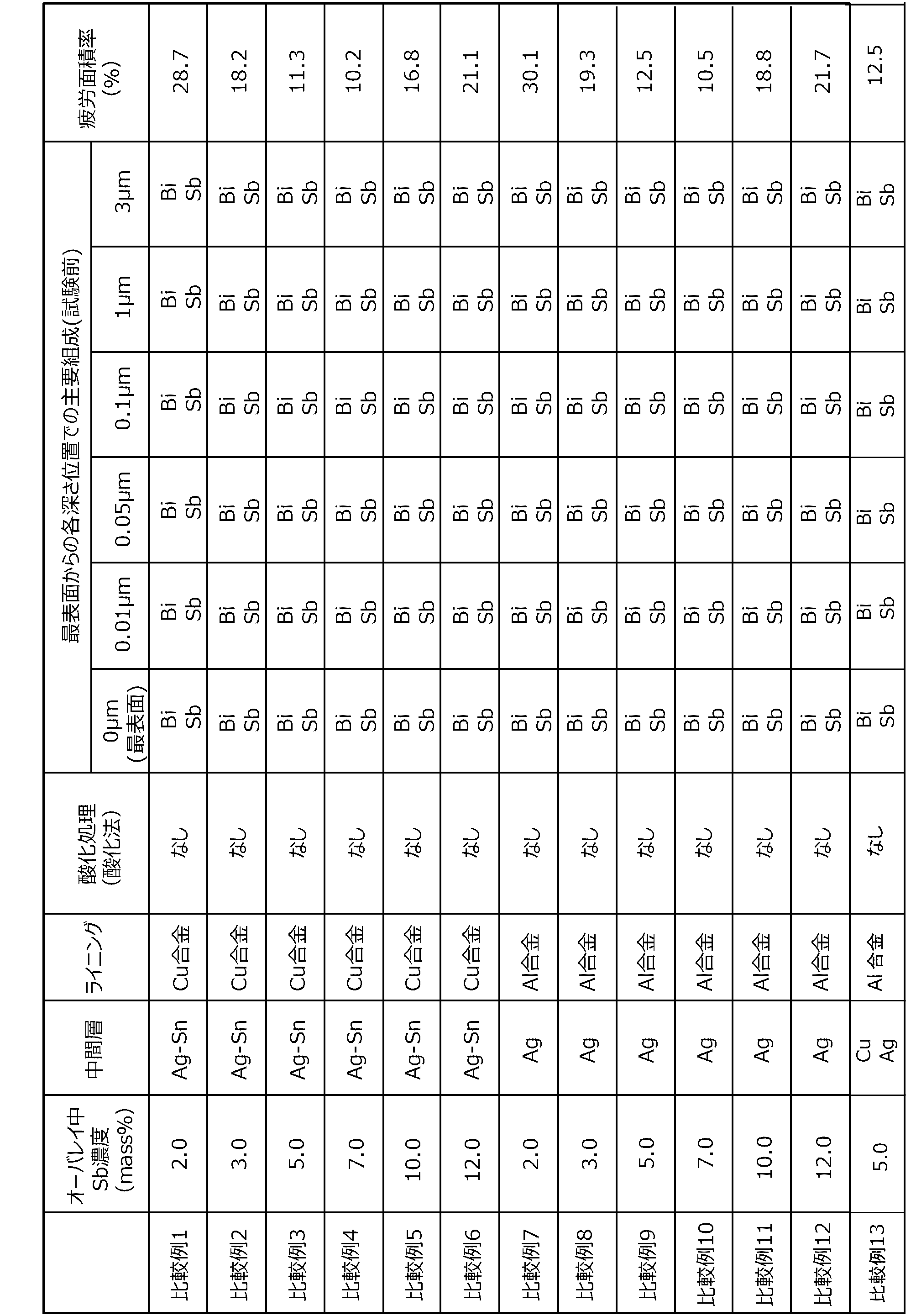
- Tables 1 and 2 are diagrams showing the main composition of each depth of the overlay 12 for a plurality of Examples and Comparative Examples having different Sb concentrations (mass concentration).
- the lining 11 is a 200 ⁇ m Cu alloy containing Sn, Ni, and Bi
- the intermediate layer 13 is 2 ⁇ m of Ag—Sn.
- the overlay 12 is a layer of 15 ⁇ m.
- the lining 11 is a 300 ⁇ m Al alloy containing Sn and Si
- the intermediate layer 13 is a 4 ⁇ m layer in which Ag is Ag
- the overlay 12 is a 15 ⁇ m layer. ..
- Example 13 and Comparative Example 13 the lining 11 is a 300 ⁇ m Al alloy containing Sn and Si, the intermediate layer 13 is a 1 ⁇ m Cu first intermediate layer, and the 5 ⁇ m Ag second intermediate layer is an overlay. 12 is a layer of 15 ⁇ m. Further, in the examples, the oxidation treatment in paraffin oil was performed, but in the comparative example, the oxidation treatment was not performed.
- the Sb concentration was 2.0% by mass to 12.0% by mass in Examples 1 to 6 and Examples 7 to 12, and also in Comparative Examples 1 to 6 and Comparative Examples 7 to 12.
- the Sb concentration is 2.0% by mass to 12.0% by mass.
- the Sb concentration is 5.0% by mass.
- the concentration of Sb in the overlay 12 can be adjusted by increasing or decreasing the concentration of Sb in the plating bath of electroplating.
- the main composition at each depth position from the outermost surface of the overlay 12 is shown. That is, the main compositions at depths of 0 ⁇ m (outermost surface), 0.01 ⁇ m, 0.05 ⁇ m, 0.1 ⁇ m, 1 ⁇ m, and 3 ⁇ m of each sample are shown.
- the main composition at each depth position was measured using a scanning X-ray photoelectron spectroscopy analyzer (PHI X-tool manufactured by ULVAC-PHI). That is, the measurement regions were set at the depths of 0 ⁇ m, 0.01 ⁇ m, 0.05 ⁇ m, 0.1 ⁇ m, 1 ⁇ m, and 3 ⁇ m in the depth direction of the overlay 12, and X-ray photoelectron spectroscopy was performed.
- the size and shape of the measurement area is a square with a side of 2 mm, and the composition existing in the measurement area is specified from the binding energy obtained for the measurement area at each depth, and the abundance ratio of each composition is quantified from the peak area ratio. It was made into.
- the main composition may be defined by various methods. For example, N compounds (N is an integer of 1 or more) may be defined as the main composition in descending order of abundance ratio. Further, the main composition may be a compound having an abundance ratio equal to or higher than a threshold value and up to N compounds having an abundance ratio higher than the threshold value. In any case, the compound with the highest abundance ratio is the main composition.
- the main composition on the outermost surface is Bi-Sb oxide (Bi-Sb-O).
- Bi-Sb-O compound is larger than the abundance ratios of other compounds and elemental metals, at least on the outermost surface.
- Bi-Sb oxide is formed as a main composition over the entire surface of the sliding surface between the overlay 12 and the mating shaft 2.
- the main composition on the outermost surface is not an oxide.
- Bi-Sb oxide is a very stable compound. Therefore, the presence of the Bi-Sb oxide on the outermost surface can protect the overlay 12. Therefore, Examples 1 to 13 in which the Bi-Sb oxide is present on the outermost surface have higher fatigue resistance than Comparative Examples 1 to 13 in which the Bi-Sb oxide is not present on the outermost surface.
- Table 1 the results of fatigue tests performed on the sliding members of Examples 1 to 13 and Comparative Examples 1 to 13 are shown as the fatigue area ratio (%).
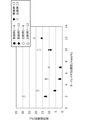
- FIG. 3 is a graph showing the fatigue area ratio (%).
- the horizontal axis is the Sb concentration in the overlay 12, and Examples 1 to 6 are plotted with black circles, Examples 7 to 12 are plotted with black squares, and Example 13 is plotted with black triangles. Comparative Examples 1 to 6 are plotted with white circles, Comparative Examples 7 to 12 are plotted with white squares, and Comparative Example 13 is plotted with white triangles.
- FIG. 2 is an explanatory diagram of a fatigue test. First, as shown in FIG. 2, a connecting rod R having columnar through holes formed at both ends in the length direction was prepared, and a test shaft H (hatching) was supported by the through holes at one end.
- An overlay 12 (black) similar to that of the sliding member 1 was formed on the inner peripheral surface of the through hole of the connecting rod R bearing the test shaft H.
- the test shaft H was supported on both outer sides of the connecting rod R in the axial direction of the test shaft H, and the test shaft H was rotated so that the sliding speed was 6.6 m / sec.
- the sliding speed is the relative speed between the surface of the overlay 12 and the test axis H.
- the end of the connecting rod R on the opposite side of the test shaft H was connected to the moving body F that reciprocates in the length direction of the connecting rod R, and the reciprocating load of the moving body F was set to 100 MPa. Further, engine oil at about 140 ° C. was supplied between the connecting rod R and the test shaft H.
- the fatigue test of the overlay 12 was performed by continuing the above state for 100 hours. Then, after the fatigue test, the inner surface (sliding surface) of the overlay 12 is photographed from a position on a straight line orthogonal to the surface so that the straight line is the main optical axis, and the photographed image is taken. An evaluation image was obtained. Then, the damaged portion of the surface of the overlay 12 projected on the evaluation image is observed and specified by a binocular (magnifying mirror), and the damaged portion area, which is the area of the damaged portion, is projected on the evaluation image. The percentage of the value divided by the area of the entire surface of 12 was measured as the fatigue area ratio.
- Bi-Sb oxide is present on the outermost surface as in Examples 1 to 13, the possibility that the element existing in the portion deeper than the outermost surface is oxidized can be reduced. Therefore, in the overlay 12, bismuth oxide (Bi 2 O 3 ) can be prevented from being generated and growing as a main composition.
- bismuth oxide since bismuth oxide is brittle, when it is formed on the overlay 12, bismuth oxide may fall off during the process of using the sliding member.
- Bi-Sb oxide when Bi-Sb oxide is present on the outermost surface as in Examples 1 to 13, it is possible to prevent Bi from being oxidized in a region deeper than the outermost surface to generate bismuth oxide. Therefore, in Examples 1 to 13, it is considered that the prevention of the formation of bismuth oxide also contributes to the improvement of fatigue resistance.
- the Sb concentration is 2.0% by mass to 12.0% by mass, but if Bi-Sb oxide is present on the surface at any Sb concentration in this concentration range, Bi-Sb oxidation occurs.
- the fatigue area rate is smaller than when there is no object. Therefore, it is considered that the fatigue resistance is improved by forming the Bi—Sb oxide at an arbitrary concentration in which the Sb concentration in the overlay 12 is more than 0% by mass.
- the Sb concentration in the overlay 12 may be controlled. For example, when it is desired to reduce the fatigue area ratio to 11% or less, it is preferable to set the Sb concentration in the overlay 12 to 3.0% by mass or more and 10.0% by mass or less.
- the main compositions are Bi-Sb oxide and antimony oxide (Sb 2) immediately below the layer in which the Bi-Sb oxide is the main composition. O 3 ).
- Bi-Sb oxide is present as the main composition in the surface layer, and at a depth of 0.1 ⁇ m immediately below the Bi-Sb oxide, the main composition is Bi-Sb oxide and antimony oxide (Sb 2 O 3).
- Sb 2 O 3 antimony oxide
- the main composition is Bi-Sb oxide and antimony oxide (Sb 2 O 3).
- no oxide was observed, and Bi and Sb were present as the main compositions.
- oxides other than Bi-Sb-O are also produced at the deep position of the overlay 12.
- the sliding member from becoming brittle due to bismuth oxide.
- the Bi-Sb oxide protects the surface to prevent the formation of bismuth oxide and tolerate fatigue. It is possible to improve the sex.
- the sliding member having an Sb concentration of 0 in the overlay 12 for example, the overlay 12 is made of Bi, Bi-Cu, Bi-Sn, etc., and the other layers are the same as those of Examples 1 to 13. Even if a certain sliding member is subjected to an oxidation treatment, it is difficult to protect the outermost surface with an oxide.
- the intermediate layer 13 and the lining 11 are different between Examples 1 to 6, Example 7 to Example 12, and Example 13. That is, the intermediate layer 13 of Examples 1 to 6 is made of Ag—Sn.
- the intermediate layer 13 of Examples 7 to 12 is made of Ag.
- the intermediate layer of Example 13 is composed of a first intermediate layer (Cu) and a second intermediate layer (Ag). Comparing these examples, the main composition of the overlay 12 is the same, and the fatigue area ratio is also very close. Further, when compared with Comparative Example 1 to Comparative Example 6, Comparative Example 7 to Comparative Example 12, and Comparative Example 13, the fatigue-resistant area is smaller in the example. Therefore, it is considered that the improvement of the fatigue-resistant area by forming the Bi-Sb oxide on the outermost surface of the overlay 12 made of Bi and Sb can be achieved regardless of the composition of the intermediate layer 13 and the lining 11.
- the main composition at each depth position from the outermost surface shown in Table 1 is the result of measurement for the sliding member before the fatigue test.
- the main composition was measured even after the fatigue test.
- no change was observed in the main composition at each depth position in both Examples 1 to 13 and Comparative Examples 1 to 13. That is, on the outermost surfaces of Comparative Examples 1 to 13, oxide was not formed as a main composition even after the fatigue test. Therefore, in the normal use process of the sliding member 1, the Bi-Sb oxide is uniformly applied over the entire surface of the sliding member 1 in a state where the oxidation treatment is not positively performed as in Comparative Examples 1 to 13. It is difficult to form. On the other hand, when the oxidation treatment is positively performed as in Examples 1 to 13, Bi-Sb oxide is uniformly formed over the entire surface of the outermost surface.
- Bi-Sb oxide is formed on the outermost surface in Comparative Examples 1 to 13. It is possible that Bi is locally oxidized to produce bismuth oxide. When bismuth oxide is generated, the bismuth oxide is brittle, and therefore the fatigue resistance is lowered due to the bismuth oxide falling off or the like. Therefore, as in Examples 1 to 13, the Bi-Sb oxide can be surely improved by forming the Bi-Sb oxide over the entire surface of the outermost surface by performing the oxidation treatment in advance.
- the sliding member 1 constituting the sliding bearing A bearing the crankshaft of the engine is exemplified, but the sliding member 1 of the present invention may be used to form the sliding bearing A for other purposes.
- the sliding member 1 of the present invention may be used to form a radial bearing such as a gear bush for a transmission, a piston pin bush, or a boss bush.
- the sliding member of the present invention may be a thrust bearing, various washers, or a swash plate for a car air conditioner compressor.
- the matrix of the lining 11 is not limited to the Cu alloy and the Al alloy, and the material of the matrix may be selected according to the hardness of the mating shaft 2. Further, the back metal 10 is not essential and may be omitted.
Landscapes
- Engineering & Computer Science (AREA)
- Chemical & Material Sciences (AREA)
- General Engineering & Computer Science (AREA)
- Mechanical Engineering (AREA)
- Materials Engineering (AREA)
- Metallurgy (AREA)
- Organic Chemistry (AREA)
- Chemical Kinetics & Catalysis (AREA)
- Electrochemistry (AREA)
- Sliding-Contact Bearings (AREA)
Abstract
Description
(1-1)摺動部材の構成:
(1-2)摺動部材の製造方法:
(2)実験結果:
(3)他の実施形態:
図1は、本発明の一実施形態にかかる摺動部材1の斜視図である。摺動部材1は、裏金10とライニング11とオーバーレイ12とを含む。摺動部材1は、中空状の円筒を直径方向に2等分した半割形状の金属部材であり、断面が半円弧状となっている。2個の摺動部材1を円筒状になるように組み合わせることにより、すべり軸受Aが形成される。すべり軸受Aは内部に形成される中空部分にて円柱状の相手軸2(エンジンのクランクシャフト)を軸受けする。相手軸2の外径はすべり軸受Aの内径よりもわずかに小さく形成されている。相手軸2の外周面と、すべり軸受Aの内周面との間に形成される隙間に潤滑油(エンジンオイル)が供給される。その際に、すべり軸受Aの内周面上を相手軸2の外周面が摺動する。
本実施形態にかかるオーバーレイ12の表面にはBi-Sb酸化物が形成されている。オーバーレイ12は、BiとSbの合金めっき皮膜を酸化させることによって形成される。ここでは、ライニング11がSn,Ni,Biを含有するCu合金であり、中間層13がAg-Snである構成を例にして摺動部材の製造方法の例を説明する。摺動部材の製造方法の位置例においては、まず、裏金10と同じ厚みを有する低炭素鋼の平面板が用意される。
以上のように、オーバーレイ12の表面に酸化膜が形成されると、摺動部材1が完成する。さらに、2個の摺動部材1を円筒状に組み合わせると、すべり軸受が形成される。以上の摺動部材1において、オーバーレイ12はBi,Sbの双方が存在すればよく(双方とも0質量%より多い)、Sb濃度は任意である。

前記実施形態においては、エンジンのクランクシャフトを軸受けするすべり軸受Aを構成する摺動部材1を例示したが、本発明の摺動部材1によって他の用途のすべり軸受Aを形成してもよい。例えば、本発明の摺動部材1によってトランスミッション用のギヤブシュやピストンピンブシュ・ボスブシュ等のラジアル軸受を形成してもよい。さらに、本発明の摺動部材は、スラスト軸受であってもよく、各種ワッシャであってもよいし、カーエアコンコンプレッサ用の斜板であってもよい。
Claims (4)
- BiとSbの合金めっき皮膜によって形成されたオーバーレイを備えた摺動部材であって、
前記オーバーレイの表面に、Bi-Sb酸化物が形成されている、
摺動部材。 - 前記オーバーレイにおけるSbの濃度が2.0質量%以上かつ12.0質量%以下である、
請求項1に記載の摺動部材。 - 前記オーバーレイにおけるSbの濃度が3.0質量%以上かつ10.0質量%以下である、
請求項1に記載の摺動部材。 - 前記オーバーレイの深さ方向において、前記Bi-Sb酸化物の直下には酸化アンチモンが形成されている、
請求項1~請求項3のいずれか一項に記載の摺動部材。
Priority Applications (4)
| Application Number | Priority Date | Filing Date | Title |
|---|---|---|---|
| US18/013,457 US12209612B2 (en) | 2020-07-22 | 2021-06-28 | Sliding member |
| JP2022538659A JP7664256B2 (ja) | 2020-07-22 | 2021-06-28 | 摺動部材 |
| EP21846620.9A EP4186618A4 (en) | 2020-07-22 | 2021-06-28 | SLIDING ELEMENT |
| CN202180037314.7A CN115667742B (zh) | 2020-07-22 | 2021-06-28 | 滑动构件 |
Applications Claiming Priority (2)
| Application Number | Priority Date | Filing Date | Title |
|---|---|---|---|
| JP2020125470 | 2020-07-22 | ||
| JP2020-125470 | 2020-07-22 |
Publications (1)
| Publication Number | Publication Date |
|---|---|
| WO2022019059A1 true WO2022019059A1 (ja) | 2022-01-27 |
Family
ID=79729399
Family Applications (1)
| Application Number | Title | Priority Date | Filing Date |
|---|---|---|---|
| PCT/JP2021/024335 Ceased WO2022019059A1 (ja) | 2020-07-22 | 2021-06-28 | 摺動部材 |
Country Status (5)
| Country | Link |
|---|---|
| US (1) | US12209612B2 (ja) |
| EP (1) | EP4186618A4 (ja) |
| JP (1) | JP7664256B2 (ja) |
| CN (1) | CN115667742B (ja) |
| WO (1) | WO2022019059A1 (ja) |
Citations (2)
| Publication number | Priority date | Publication date | Assignee | Title |
|---|---|---|---|---|
| JP2014185378A (ja) * | 2013-03-25 | 2014-10-02 | Daido Metal Co Ltd | 摺動部材及び摺動部材の製造方法 |
| WO2019198369A1 (ja) * | 2018-04-11 | 2019-10-17 | 大豊工業株式会社 | 摺動部材 |
Family Cites Families (8)
| Publication number | Priority date | Publication date | Assignee | Title |
|---|---|---|---|---|
| ATE12760T1 (de) * | 1981-10-09 | 1985-05-15 | Bosch Gmbh Robert | Gegen umwelteinfluesse bestaendiges mehrschichtsystem fuer waermeschutzanwendung. |
| JP2933701B2 (ja) * | 1990-10-09 | 1999-08-16 | 臼井国際産業株式会社 | 耐摩耗性摺動部材及びその製造方法 |
| JP3054589B2 (ja) * | 1996-02-29 | 2000-06-19 | 大同メタル工業株式会社 | すべり軸受の軸受構造 |
| JP3725942B2 (ja) * | 1996-09-26 | 2005-12-14 | オイレス工業株式会社 | 摺動部材用樹脂組成物および摺動部材 |
| JP3693256B2 (ja) * | 2003-05-29 | 2005-09-07 | 大同メタル工業株式会社 | 摺動部材 |
| DE112018000075T5 (de) * | 2017-07-21 | 2019-06-06 | Taiho Kogyo Co., Ltd. | Gleitkörper und gleitlager |
| DE102017216110A1 (de) * | 2017-09-12 | 2019-03-14 | Federal-Mogul Wiesbaden Gmbh | Gleitlack, Gleitelement mit einem solchen und dessen Verwendung |
| JP6636090B2 (ja) * | 2018-06-13 | 2020-01-29 | 大豊工業株式会社 | 摺動部材 |
-
2021
- 2021-06-28 CN CN202180037314.7A patent/CN115667742B/zh active Active
- 2021-06-28 EP EP21846620.9A patent/EP4186618A4/en active Pending
- 2021-06-28 US US18/013,457 patent/US12209612B2/en active Active
- 2021-06-28 WO PCT/JP2021/024335 patent/WO2022019059A1/ja not_active Ceased
- 2021-06-28 JP JP2022538659A patent/JP7664256B2/ja active Active
Patent Citations (3)
| Publication number | Priority date | Publication date | Assignee | Title |
|---|---|---|---|---|
| JP2014185378A (ja) * | 2013-03-25 | 2014-10-02 | Daido Metal Co Ltd | 摺動部材及び摺動部材の製造方法 |
| JP6087684B2 (ja) | 2013-03-25 | 2017-03-01 | 大同メタル工業株式会社 | 摺動部材及び摺動部材の製造方法 |
| WO2019198369A1 (ja) * | 2018-04-11 | 2019-10-17 | 大豊工業株式会社 | 摺動部材 |
Non-Patent Citations (1)
| Title |
|---|
| See also references of EP4186618A4 |
Also Published As
| Publication number | Publication date |
|---|---|
| US12209612B2 (en) | 2025-01-28 |
| JP7664256B2 (ja) | 2025-04-17 |
| US20230235787A1 (en) | 2023-07-27 |
| EP4186618A4 (en) | 2024-07-17 |
| JPWO2022019059A1 (ja) | 2022-01-27 |
| EP4186618A1 (en) | 2023-05-31 |
| CN115667742A (zh) | 2023-01-31 |
| CN115667742B (zh) | 2025-06-17 |
Similar Documents
| Publication | Publication Date | Title |
|---|---|---|
| JP6636090B2 (ja) | 摺動部材 | |
| US20210040988A1 (en) | Sliding member and sliding bearing | |
| JP6621562B1 (ja) | 摺動部材 | |
| JP6731969B2 (ja) | 摺動部材 | |
| JP6895338B2 (ja) | 摺動部材およびすべり軸受 | |
| JP7664256B2 (ja) | 摺動部材 | |
| CN113302343B (zh) | 滑动构件 | |
| JP6777594B2 (ja) | 摺動部材およびすべり軸受 | |
| JP6321436B2 (ja) | 摺動部材およびすべり軸受 | |
| JP6944019B2 (ja) | 摺動部材およびすべり軸受 | |
| JP6924315B2 (ja) | 摺動部材およびすべり軸受 | |
| JP6762915B2 (ja) | 摺動部材およびすべり軸受 | |
| WO2023167170A1 (ja) | アルミニウム青銅合金および該合金を用いた摺動部材 | |
| JP2019123914A (ja) | 摺動部材 |
Legal Events
| Date | Code | Title | Description |
|---|---|---|---|
| 121 | Ep: the epo has been informed by wipo that ep was designated in this application |
Ref document number: 21846620 Country of ref document: EP Kind code of ref document: A1 |
|
| ENP | Entry into the national phase |
Ref document number: 2022538659 Country of ref document: JP Kind code of ref document: A |
|
| NENP | Non-entry into the national phase |
Ref country code: DE |
|
| ENP | Entry into the national phase |
Ref document number: 2021846620 Country of ref document: EP Effective date: 20230222 |
|
| WWG | Wipo information: grant in national office |
Ref document number: 202180037314.7 Country of ref document: CN |