WO2022019178A1 - Coupleur directionnel - Google Patents
Coupleur directionnel Download PDFInfo
- Publication number
- WO2022019178A1 WO2022019178A1 PCT/JP2021/026286 JP2021026286W WO2022019178A1 WO 2022019178 A1 WO2022019178 A1 WO 2022019178A1 JP 2021026286 W JP2021026286 W JP 2021026286W WO 2022019178 A1 WO2022019178 A1 WO 2022019178A1
- Authority
- WO
- WIPO (PCT)
- Prior art keywords
- filter
- signal
- directional coupler
- frequency
- pass
- Prior art date
- Legal status (The legal status is an assumption and is not a legal conclusion. Google has not performed a legal analysis and makes no representation as to the accuracy of the status listed.)
- Ceased
Links
Images






Classifications
-
- H—ELECTRICITY
- H01—ELECTRIC ELEMENTS
- H01P—WAVEGUIDES; RESONATORS, LINES, OR OTHER DEVICES OF THE WAVEGUIDE TYPE
- H01P5/00—Coupling devices of the waveguide type
- H01P5/12—Coupling devices having more than two ports
- H01P5/16—Conjugate devices, i.e. devices having at least one port decoupled from one other port
- H01P5/18—Conjugate devices, i.e. devices having at least one port decoupled from one other port consisting of two coupled guides, e.g. directional couplers
-
- H—ELECTRICITY
- H01—ELECTRIC ELEMENTS
- H01P—WAVEGUIDES; RESONATORS, LINES, OR OTHER DEVICES OF THE WAVEGUIDE TYPE
- H01P1/00—Auxiliary devices
- H01P1/10—Auxiliary devices for switching or interrupting
- H01P1/12—Auxiliary devices for switching or interrupting by mechanical chopper
- H01P1/127—Strip line switches
-
- H—ELECTRICITY
- H01—ELECTRIC ELEMENTS
- H01P—WAVEGUIDES; RESONATORS, LINES, OR OTHER DEVICES OF THE WAVEGUIDE TYPE
- H01P1/00—Auxiliary devices
- H01P1/16—Auxiliary devices for mode selection, e.g. mode suppression or mode promotion; for mode conversion
- H01P1/162—Auxiliary devices for mode selection, e.g. mode suppression or mode promotion; for mode conversion absorbing spurious or unwanted modes of propagation
-
- H—ELECTRICITY
- H01—ELECTRIC ELEMENTS
- H01P—WAVEGUIDES; RESONATORS, LINES, OR OTHER DEVICES OF THE WAVEGUIDE TYPE
- H01P1/00—Auxiliary devices
- H01P1/20—Frequency-selective devices, e.g. filters
- H01P1/213—Frequency-selective devices, e.g. filters combining or separating two or more different frequencies
-
- H—ELECTRICITY
- H03—ELECTRONIC CIRCUITRY
- H03H—IMPEDANCE NETWORKS, e.g. RESONANT CIRCUITS; RESONATORS
- H03H7/00—Multiple-port networks comprising only passive electrical elements as network components
- H03H7/01—Frequency selective two-port networks
- H03H7/0153—Electrical filters; Controlling thereof
- H03H7/0161—Bandpass filters
Definitions
- the present invention relates to a directional coupler.
- Patent Document 1 discloses a directional coupler including a main line and a sub line.
- a variable filter circuit including a plurality of filters is connected between the sub line of the directional coupler and the coupling port.
- the desired signal can be extracted from the coupling port with a certain degree of accuracy by using a filter that allows only the desired signal to pass through.
- the detector when a detector is connected to the coupling port, the detector generates distortion components such as harmonics of the input desired signal.
- the strain component returns to the filter through the coupling port and is reflected by the filter.
- the distortion component reflected by the filter is input to the detector again, and the detection accuracy is deteriorated.
- an object of the present invention is to provide a directional coupler capable of improving the detection accuracy of the connected detector when the detector is connected.
- the directional coupler includes a main line, a sub line electromagnetically coupled to the main line, an output terminal connected to one end of the sub line, and one end and an output terminal of the sub line.
- a first filter connected in between and a second filter having a pass band higher than the pass band of the first filter are provided, one end of the second filter is connected to an output terminal, and the other end of the second filter is connected. , Terminated.
- the detection accuracy of the connected detector can be improved.
- FIG. 1 is a diagram showing a configuration of a directional coupler according to the first embodiment.
- FIG. 2 is a diagram showing a configuration example of a plurality of filters included in the directional coupler according to the first embodiment.
- FIG. 3 is a diagram showing the insertion loss characteristics of each filter shown in FIG.
- FIG. 4 is a diagram showing another configuration example of a plurality of filters included in the directional coupler according to the first embodiment.
- FIG. 5 is a diagram showing the insertion loss characteristics of each filter shown in FIG.
- FIG. 6 is a diagram for explaining a signal flowing in the directional coupler according to the comparative example.
- FIG. 7 is a diagram for explaining a signal flowing in the directional coupler according to the first embodiment.
- FIG. 8 is a diagram showing the configuration of the directional coupler according to the second embodiment.
- FIG. 9 is a circuit diagram showing an example of a variable termination circuit included in the directional coupler according to the second embodiment.
- FIG. 10 is a diagram for explaining a signal flowing in the directional coupler according to the second embodiment.
- FIG. 11 is a diagram showing a configuration of a directional coupler according to the third embodiment.
- FIG. 12 is a diagram for explaining a signal flowing in the directional coupler according to the third embodiment.
- FIG. 13 is a diagram showing a modified example of the configuration of a plurality of filters included in the directional coupler according to each embodiment.
- each figure is a schematic diagram and is not necessarily exactly illustrated. Therefore, for example, the scales and the like do not always match in each figure. Further, in each figure, substantially the same configuration is designated by the same reference numeral, and duplicate description will be omitted or simplified.
- directly connected means that the circuit is directly connected by a connection terminal and / or a wiring conductor without using other circuit elements.
- the term “connected” includes not only the case of being directly connected by a connection terminal and a wiring conductor, but also the case of being electrically connected via another circuit element.
- “connected between A and B” means that both A and B are connected between A and B.
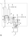
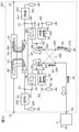
- FIG. 1 is a diagram showing a configuration of a directional coupler 1 according to the present embodiment.
- the directional coupler 1 includes a main line 10, a sub line 20, a filter 30, a filter 40, a coupling output terminal 50, and termination circuits 60 and 70.
- the directional coupler 1 is provided so that the detector 2 can detect a high frequency signal transmitted through the main line 10.
- the main line 10 has two input / output terminals 11 and 12.
- the input / output terminal 11 is connected to at least one of a transmission circuit that generates a high frequency signal for transmission and a reception circuit that processes the high frequency signal received by the antenna.
- the input / output terminal 12 is connected to the antenna.
- the input / output terminal 11 may be connected to the antenna, and the input / output terminal 12 may be connected to the transmission circuit or the reception circuit.
- the sub line 20 is electromagnetically coupled to the main line 10.
- the auxiliary line 20 has one end 21 and the other end 22.
- One end 21 is connected to the combined output terminal 50 via a filter 30.
- the other end 22 is connected to the terminal circuit 70.
- the filter 30 is an example of the first filter, and is connected between one end 21 of the sub line 20 and the coupling output terminal 50.
- the node N1 which is one end of the filter 30 is connected to one end 21 of the sub line 20.
- the node N3, which is the other end of the filter 30, is connected to the combined output terminal 50.
- the filter 30 has a predetermined pass band and is configured to allow a desired signal to pass through. Specifically, the filter 30 passes a signal having a target frequency detected by the detector 2.
- the filter 40 is an example of the second filter, and is connected between the coupling output terminal 50 and the ground.
- the node N3, which is one end of the filter 40, is connected to the combined output terminal 50.
- the node N2, which is the other end of the filter 40, is terminated. Specifically, the node N2 of the filter 40 is connected to the ground via the terminal circuit 60.
- the filter 40 has a pass band higher than the pass band of the filter 30. Specifically, the filter 40 passes a signal in the harmonic band of the target frequency detected by the detector 2.
- the pass band of the filter 40 may include a pass band higher than the pass band of the filter 30.
- the filter 40 may be a bandpass filter or a highpass filter having a passband higher than the passband of the filter 30, or a band elimination filter that blocks only the passband of the filter 30. You may.
- the filters 30 and 40 may constitute a diplexer.
- the node N3 is a common terminal of the diplexer, and the nodes N1 and N2 are demultiplexing input / output terminals, respectively.
- the frequency bands that can pass through each demultiplexing input / output terminal are, for example, complementary to each other. Specific configurations of the filters 30 and 40 and examples of frequency characteristics will be described later.
- the combined output terminal 50 is an example of an "output terminal" and is connected to one end 21 of the sub line 20. Specifically, the coupling output terminal 50 is connected to one end 21 of the sub line 20 via the filter 30. Further, the coupling output terminal 50 is connected to the ground via the filter 40 and the termination circuit 60. The detector 2 is connected to the coupled output terminal 50.
- the termination circuit 60 is connected to the node N2 of the filter 40.
- the impedance of the termination circuit 60 is adjusted to a predetermined value so that the signal passing through the filter 40 can be absorbed and consumed.
- the impedance of the terminal circuit 60 is adjusted to an appropriate value so as to absorb and consume the distortion signal 92 (see FIG. 7) generated by the detector 2.
- the terminal circuit 70 is connected to the other end 22 of the sub line 20.
- the impedance of the termination circuit 70 is adjusted to a predetermined value so that the signal of the fundamental frequency f0 reflected from the input / output terminal 12 to the input / output terminal 11 can be absorbed and consumed among the high frequency signals transmitted through the main line 10. ing.
- the termination circuit 70 is, for example, a 50 ⁇ resistor.
- the directional coupler 1 configured as described above is used for detecting a high frequency signal transmitted on the main line 10.
- the high frequency signal is a signal compliant with a communication standard such as Wi-Fi (registered trademark), LTE (Long Term Evolution) or 5G (5th Generation).
- the directional coupler 1 is arranged, for example, in the front end portion of a multimode / multiband compatible mobile phone.
- a part of the high frequency signal transmitted on the main line 10 is input to the detector 2 via the sub line 20, the filter 30, and the coupling output terminal 50.
- the detector 2 detects the signal power of the input signal and outputs the detection result from the detection result output terminal 3.
- the detection result output terminal 3 is connected to, for example, a transmission circuit or a reception circuit or a control circuit of these circuits. Thereby, for example, the amplification factor of the amplifier provided in the transmission circuit or the reception circuit can be controlled. By improving the detection accuracy, the accuracy and reliability of various controls can be improved.
- FIG. 2 is a diagram showing a configuration example of a plurality of filters included in the directional coupler 1 according to the present embodiment.
- the low-pass filter 30L shown in FIG. 2 is an example of the filter 30 shown in FIG.
- the high-pass filter 40H is an example of the filter 40 shown in FIG.
- the low-pass filter 30L and the high-pass filter 40H constitute, for example, a diplexer.
- FIG. 3 is a diagram showing the insertion loss characteristics of each filter shown in FIG.
- the horizontal axis represents frequency and the vertical axis represents insertion loss.
- the thick solid line in FIG. 3 represents the frequency characteristic of the insertion loss of the low-pass filter 30L.
- the thick dashed line represents the frequency characteristic of the insertion loss of the high-pass filter 40H.
- the thick dotted line represents the frequency characteristics of the reflection loss of the low-pass filter 30L and the high-pass filter 40H as seen from the node N3.
- the low-pass filter 30L passes a signal having a frequency fl or less and blocks a signal having a frequency fl or higher.
- the frequency fl is the corner frequency of the low-pass filter 30L.
- the low-pass filter 30L has a range of frequency fl or less as a pass band.
- the corner frequency is also called the cutoff frequency or cutoff frequency.
- the corner frequency corresponds to the frequency at which the insertion loss becomes about 3 dB in the frequency characteristic of the low-pass filter 30L.
- the corner frequency is also synonymous with the high-pass filter, band-pass filter, and band elimination filter described later.
- the high-pass filter 40H passes signals above the frequency fh and blocks signals below the frequency fh.
- the frequency fh is the corner frequency of the high-pass filter 40H.
- the high-pass filter 40H has a range of frequency fh or higher as a pass band.
- the low-pass filter 30L and the high-pass filter 40H have their respective pass bands complementary to each other.
- the corner frequency fl of the low-pass filter 30L is equal to the corner frequency fh of the high-pass filter 40H.
- "equal" not only means an exact match, but also includes a case where there is an error of about 10% or less. That is, the corner frequency fl of the low-pass filter 30L and the corner frequency fh of the high-pass filter 40H do not have to completely match, and can be regarded as substantially equal. The same applies to the case of the bandpass filter and the band elimination filter described later.
- the corner frequencies of the two filters are equal, the reflection loss when looking at the two filters from the node N3 is suppressed to be sufficiently small in the entire frequency band. Therefore, the signal input from the node N3 to the two filters passes through one of the two filters without being reflected by either of the two filters. That is, of the signals input from the combined output terminal 50 to the two filters via the node N3, the signal reflected by the two filters and returned from the combined output terminal 50 to the detector 2 is sufficiently suppressed.
- the fundamental frequency f0 is the frequency of the fundamental wave of the high frequency signal transmitted on the main line 10. That is, the fundamental frequency f0 is the frequency (that is, the target frequency) of the signal to be detected by the detector 2.
- the 2nd harmonic frequency 2f0 and the 3rd harmonic frequency 3f0 are frequencies of unnecessary signals that should not be input to the detector 2.
- the fundamental frequency f0 is included in the pass band (fl or less) of the low-pass filter 30L.
- the frequencies 2f0 and 3f0 are included in the pass band (fh or more) of the high-pass filter 40H.
- the desired signal (fundamental wave) having the fundamental frequency f0 passes through the low-pass filter 30L and is input to the detector 2 via the node N3 and the coupling output terminal 50.
- the detection accuracy of the detector 2 can be improved.
- the two filters 30 and 40 included in the directional coupler 1 are not limited to the example shown in FIG.
- the filters 30 and 40 may be a bandpass filter and a band elimination filter.
- FIG. 4 is a diagram showing another configuration example of a plurality of filters included in the directional coupler 1 according to the present embodiment.
- the bandpass filter 30B shown in FIG. 4 is an example of the filter 30 shown in FIG.
- the band elimination filter 40E is an example of the filter 40 shown in FIG.
- the bandpass filter 30B and the band elimination filter 40E constitute, for example, a diplexer.
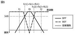
- FIG. 5 is a diagram showing the insertion loss characteristics of each filter shown in FIG. In FIG. 4, the horizontal axis represents frequency and the vertical axis represents insertion loss.
- the thick solid line in FIG. 4 represents the frequency characteristic of the insertion loss of the bandpass filter 30B.
- the thick dashed line represents the frequency characteristic of the insertion loss of the band elimination filter 40E.
- the thick dotted line represents the frequency characteristic of the reflection loss of the bandpass filter 30B and the band elimination filter 40E as seen from the node N3.
- the bandpass filter 30B passes signals having a frequency of fb1 or more and fb2 or less, and blocks signals having a frequency of less than fb1 and signals having a frequency of more than fb2.
- the frequency fb1 is a corner frequency on the low frequency side of the bandpass filter 30B.
- the frequency fb2 is a corner frequency on the high frequency side of the bandpass filter 30B.
- the bandpass filter 30B has a range of fb1 or more and fb2 or less as a pass band.
- the band elimination filter 40E passes a signal having a frequency fe1 or less and a signal having a frequency fe2 or more, and blocks a signal larger than the frequency fe1 and less than the frequency fe2.
- the frequency fe1 is a corner frequency on the low frequency side of the band elimination filter 40E.
- the frequency fe2 is a corner frequency on the high frequency side of the band elimination filter 40E.
- the band elimination filter 40E has a range of frequency fe1 or less and a range of frequency fe2 or more as pass bands, respectively.
- One of the pass bands of the band elimination filter 40E (range of fe2 or more) is higher than the pass band of the bandpass filter 30B.
- the bandpass filter 30B and the band elimination filter 40E have their respective pass bands complementary to each other.
- the corner frequency fb1 of the bandpass filter 30B is equal to the corner frequency fe1 of the band elimination filter 40E.
- the corner frequency fb2 of the bandpass filter 30B is equal to the corner frequency fe2 of the band elimination filter 40E.
- the reflection loss when the two filters are viewed from the node N3 is suppressed to be sufficiently small in the entire frequency band. Therefore, of the signals input from the combined output terminal 50 to the two filters via the node N3, the signal reflected by the two filters and returned from the combined output terminal 50 to the detector 2 is sufficiently suppressed.
- the desired signal having the fundamental frequency f0 passes through the bandpass filter 30B and is input to the detector 2 via the node N3 and the coupled output terminal 50. Since unnecessary signals other than the fundamental wave do not substantially pass through the bandpass filter 30B, the detection accuracy of the detector 2 can be improved.
- the low-pass filter 30L, the high-pass filter 40H, the bandpass filter 30B, and the band elimination filter 40E are LC filters including at least one of a capacitor and an inductor, respectively.
- at least one of the low-pass filter 30L, the high-pass filter 40H, the band-pass filter 30B and the band elimination filter 40E may include a surface acoustic wave filter such as a SAW (Surface Acoustic Wave) filter or a BAW (Bulk Acoustic Wave) filter. ..
- at least one of the low-pass filter 30L, the high-pass filter 40H, the bandpass filter 30B, and the band elimination filter 40E may be a filter formed in an integrated passive device (IPD: Integrated Passive Device).
- IPD integrated Passive Device
- FIG. 6 is a diagram for explaining a signal flowing in the directional coupler 1x according to the comparative example.
- FIG. 7 is a diagram for explaining a signal flowing in the directional coupler 1 according to the present embodiment.
- the directional coupler 1x according to the comparative example is different from the directional coupler 1 according to the present embodiment in that it does not include the filter 40 and the termination circuit 60.
- a high frequency signal is transmitted from the input / output terminal 11 to the input / output terminal 12 on the main line 10.
- a part of the high frequency signal transmitted on the main line 10 flows through the sub line 20 as a coupled signal by electromagnetic coupling between the main line 10 and the sub line 20.
- the coupled signal includes a fundamental wave signal 90 having a fundamental frequency f0 of a high frequency signal and an unnecessary wave signal 91 other than the fundamental wave signal 90.
- the unwanted wave signal 91 is, for example, a distorted signal generated in a transmission circuit or the like.
- both the fundamental wave signal 90 and the unnecessary wave signal 91 are input to the filter 30 from one end 21 of the sub line 20 via the node N1. Since the filter 30 passes the fundamental wave signal 90, the fundamental wave signal 90 that has passed through the filter 30 is input to the detector 2. As a result, the detector 2 detects the fundamental wave signal 90.
- the unwanted wave signal 91 cannot pass through the filter 30 and is reflected by the filter 30. If the filter 30 is not provided and the unnecessary wave signal 91 is input to the detector 2, an error occurs in the power of the detected signal and the detection accuracy is lowered. On the other hand, in the directional couplers 1x and 1, since the unnecessary wave signal 91 is not input to the detector 2 by the filter 30, the detection accuracy in the detector 2 can be improved.
- the distortion signal 92 is generated.
- the distorted signal 92 corresponds to the harmonics of the fundamental wave signal 90. That is, the main frequency of the distorted signal 92 is a frequency twice or three times the fundamental frequency.
- the distortion signal 92 generated by the detector 2 returns to the filter 30 via the coupling output terminal 50. Since the distorted signal 92 is not included in the pass band of the filter 30, it is reflected by the filter 30 and returns to the detector 2 via the coupled output terminal 50. The distortion signal 92 returned to the detector 2 deteriorates the detection accuracy of the detector 2.
- the accuracy of the detector 2 cannot be improved due to the influence of the distortion signal 92.
- a filter 40 is connected to the coupling output terminal 50.
- the filter 40 is configured to pass the distorted signal 92 without passing the fundamental wave signal 90. Therefore, the distortion signal 92 input from the coupling output terminal 50 to the node N3 passes through the filter 40.
- the node N2 which is the other end of the filter 40, is terminated by the termination circuit 60. Specifically, since the impedance of the termination circuit 60 is adjusted so that the distortion signal 92 can be appropriately absorbed and consumed, the distortion signal 92 that has passed through the filter 40 is absorbed and consumed by the termination circuit 60.
- the directional coupler 1 As described above, in the directional coupler 1 according to the present embodiment, it is possible to suppress the distortion signal 92 from returning to the detector 2. Therefore, according to the directional coupler 1, the detection accuracy of the detector 2 can be improved.
- the directional coupler 1 has a main line 10, a sub line 20 that is electromagnetically coupled to the main line 10, and a coupling output terminal connected to one end 21 of the sub line 20.
- the 50 is provided with a filter 30 connected between one end 21 of the sub-line 20 and the coupling output terminal 50, and a filter 40 having a pass band higher than the pass band of the filter 30.
- One end of the filter 40 is connected to the coupling output terminal 50, and the other end of the filter 40 is terminated.
- the detector 2 when the detector 2 is connected to the coupled output terminal 50, the detector 2 can be made to input the fundamental wave signal 90 of the target frequency, and the unnecessary wave signal 91 is input. It can be suppressed by the filter 30. Further, since the distortion signal 92 generated by the detector 2 passes through the filter 40 and is absorbed and consumed, it is suppressed that the distortion signal 92 returns to the detector 2. As described above, the unnecessary wave signal 91 and the distorted signal 92 are less likely to be input to the detector 2, so that the detection accuracy can be improved.
- the distortion signal 92 since the distortion signal 92 does not pass through the filter 30, it is suppressed from being mixed into the main line 10 via the sub line 20. If the distortion signal 92 is mixed in the main line 10, there is a risk of causing unnecessary radiation from the antenna and obstacles to the transmitter operation such as the generation of intermodulation distortion. According to the directional coupler 1 according to the present embodiment, since the distortion signal 92 is suppressed from being mixed into the main line 10, it is possible to suppress the occurrence of obstacles to the transmitter operation.
- a circuit including a switch that causes a distortion signal to be generated and a plurality of filters are connected to the other end side of the sub line.
- the main difference is that it is done.
- the differences from the first embodiment will be mainly described, and the common points will be omitted or simplified.
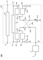
- FIG. 8 is a diagram showing a configuration of a directional coupler 101 according to the present embodiment.
- the directional coupler 101 includes a variable terminating circuit 170 instead of the terminating circuit 70 as compared with the directional coupler 1 according to the first embodiment. Further, the directional coupler 101 includes a filter 130, a filter 140, a termination circuit 160, and a switch circuit 180.
- the filter 130 is an example of a third filter, and is connected between the other end 22 of the sub line 20 and the variable termination circuit 170.
- the node N4 which is one end of the filter 130, is connected to the other end 22 of the sub line 20.
- the node N6, which is the other end of the filter 130, is connected to the variable termination circuit 170. In this embodiment, the node N6 is connected to the variable termination circuit 170 via the switch circuit 180.
- the filter 130 has a predetermined pass band and is configured to allow a desired signal to pass through. Specifically, the filter 130 passes a signal having a target frequency detected by the detector 2.
- the filter 130 is a filter having the same pass band as the filter 30, but is not limited to this.
- the filter 130 may be a band-pass filter 30B.
- the filter 130 may be a lowpass filter 30L.
- the modifications applicable to the filter 30 are also applicable to the filter 130.
- the filter 140 is an example of the fourth filter, and is connected between the variable termination circuit 170 and the ground.
- the node N6, which is one end of the filter 140, is connected to the variable termination circuit 170.
- the node N5, which is the other end of the filter 140, is terminated. Specifically, the node N5 of the filter 140 is connected to the ground via the terminal circuit 160.
- the filter 140 has a pass band higher than the pass band of the filter 130. Specifically, the filter 140 passes a signal in the harmonic band of the target frequency detected by the detector 2.
- the pass band of the filter 140 may include a pass band higher than the pass band of the filter 130.
- the filter 140 may be a band pass filter or a high pass filter having a pass band higher than the pass band of the filter 130, or may be a band elimination filter that blocks only the pass band of the filter 130.
- the filter 140 is a filter having the same pass band as the filter 40, but is not limited to this.
- the filter 140 may be a band elimination filter 40E.
- the filter 140 may be a high-pass filter 40H.
- the modifications applicable to the filter 40 are also applicable to the filter 140.
- the termination circuit 160 is connected to the node N5 of the filter 140.
- the impedance of the termination circuit 160 is adjusted to a predetermined value so that the signal passing through the filter 140 can be absorbed and consumed. Specifically, the impedance of the termination circuit 160 is adjusted to an appropriate value so as to absorb and consume the distortion signals 94 and 95 (see FIG. 10) generated by the switch circuit 180 or the variable termination circuit 170.
- the variable termination circuit 170 is an example of a termination circuit connected to the other end 22 of the sub line 20.
- the variable termination circuit 170 is a termination circuit whose impedance can be changed.
- FIG. 9 is a circuit diagram showing an example of a variable termination circuit 170 included in the directional coupler 101 according to the present embodiment.
- the variable termination circuit 170 includes three resistors R1 to R3, three capacitors C1 to C3, six switches SW1 to SW6, and a terminal 171.
- the terminal 171 is connected to the other end 22 of the sub line 20.
- the terminal 171 is connected to the other end 22 of the sub line 20 via the filter 130 and the switch circuit 180.
- the resistors R1 to R3 and the capacitors C1 to C3 are connected in series with one of the six switches SW1 to SW6, respectively.
- a series circuit of the resistor and the switch and a series circuit of the capacitor and the switch are connected in parallel between the terminal 171 and the ground.
- the resistance values of the resistors R1 to R3 may be equal to or different from each other.
- the capacitance values of the capacitors C1 to C3 may be equal to or different from each other.
- the switch may not be connected to one of the three resistors R1 to R3.
- a switch may not be connected to one of the three capacitors C1 to C3.
- the switches SW1 to SW6 are switching elements such as MOSFETs (Metal Oxide Semiconductor Field Effect Transistor) and the like.
- the switches SW1 to SW6 can be switched on / off (conducting / non-conducting). This makes it possible to change the impedance of the variable termination circuit 170.
- the switches SW1 to SW6 are adjusted based on the fundamental frequency f0 of the high frequency signal transmitted on the main line 10.
- the on / off of the switches SW1 to SW6 is controlled so that the impedance of the variable termination circuit 170 becomes a value such that the signal of the fundamental frequency f0 can be sufficiently absorbed and consumed by the variable termination circuit 170.
- the variable termination circuit 170 may include one or more inductors. Further, the circuit configuration of the variable termination circuit 170 is not particularly limited. The variable termination circuit 170 may not include a resistor or a capacitor.
- the switch circuit 180 includes an example of a first switch circuit connected between the filter 30 and the coupling output terminal 50. Further, the switch circuit 180 includes an example of a second switch circuit connected between the filter 130 and the variable termination circuit 170.
- the switch circuit 180 has four terminals 181 to 184.
- Terminal 181 is connected to node N3.
- the terminal 182 is connected to the combined output terminal 50.
- Terminal 183 is connected to node N6.
- Terminal 184 is connected to the variable termination circuit 170.
- the node N3 which is the end of each of the filters 30 and 40, is connected to one of the coupled output terminal 50 and the variable termination circuit 170 via the switch circuit 180. Further, the node N6, which is the end of each of the filters 130 and 140, is connected to the other of the coupled output terminal 50 and the variable termination circuit 170 via the switch circuit 180.
- the switch circuit 180 one end 21 of the sub line 20 is connected to the coupling output terminal 50 via the filter 30, and the other end 22 of the sub line 20 is a variable termination circuit via the filter 130.
- the second connection state to connect to 170 is switched.
- the first connection state is a state in which the terminal 181 and the terminal 182 are connected (conducting), and the terminal 183 and the terminal 184 are connected (conducting).
- the second connection state is a state in which the terminal 181 and the terminal 184 are connected (conducting), and the terminal 183 and the terminal 182 are connected (conducting). Conduction and non-conduction between the terminals of the switch circuit 180 are switched by using a switching element such as a MOSFET.
- the end of the sub line 20 connected to the coupling output terminal 50 can be switched between one end 21 and the other end 22.
- This enables bidirectional detection in the detector 2. That is, the detector 2 can detect not only the fundamental wave signal 90 of the traveling wave but also the fundamental wave signal of the reflected wave.
- FIG. 10 is a diagram for explaining a signal flowing in the directional coupler 101 according to the present embodiment.
- the fundamental wave signal 90, the unnecessary wave signal 91, and the distorted wave signal 92 are the same as those in the first embodiment. Therefore, the directional coupler 101 according to the present embodiment can improve the detection accuracy as in the first embodiment.
- the reflected wave is taken out as a reflected wave coupling signal to the sub-line 20 by electromagnetic coupling between the main line 10 and the sub-line 20 in the same manner as the traveling wave.
- the reflected wave coupling signal includes a reflected wave fundamental wave signal 90r having a fundamental frequency f0.
- the reflected wave fundamental wave signal 90r is input to the filter 130 from the other end 22 of the sub line 20 via the node N4. Since the filter 130 passes the reflected wave fundamental wave signal 90r, the reflected wave fundamental wave signal 90r reaches the variable termination circuit 170 from the node N6 via the switch circuit 180. Since the impedance of the variable termination circuit 170 is adjusted so that the reflected wave fundamental wave signal 90r can be absorbed and consumed, the reflected wave fundamental wave signal 90r is absorbed and consumed by the variable termination circuit 170. Therefore, since the reflected wave fundamental wave signal 90r is suppressed from returning to the sub line 20 and reaching the coupled output terminal 50, it is possible to suppress a decrease in the detection accuracy of the detector 2. Further, since the reflected wave fundamental wave signal 90r is suppressed from returning to the main line 10 via the sub line 20, it is possible to suppress the occurrence of obstacles to the transmitter operation.
- variable termination circuit 170 and the switch circuit 180 include a switching element for switching between conduction and non-conduction of wiring.
- a constant distortion signal is generated.
- the switch circuit 180 generates distortion signals 93 and 94
- the variable termination circuit 170 generates distortion signals 95.
- the distorted signals 93 to 95 are, for example, signals having a frequency higher than the fundamental frequency f0.
- the distortion signal 93 is generated in the switch circuit 180 and flows toward the node N3. Since the distorted signal 93 is a signal having a frequency different from the fundamental frequency f0, it does not pass through the filter 30. Therefore, since the distortion signal 93 is suppressed from being mixed into the main line 10 via the sub line 20, it is possible to suppress the occurrence of a failure in the transmitter operation.
- the pass band of the filter 30 and the pass band of the filter 40 are in a complementary relationship, the distortion signal 93 that does not pass through the filter 30 passes through the filter 40 and is absorbed and consumed by the termination circuit 60. That is, since the distortion signal 93 is not reflected by the filters 30 and 40, it is suppressed from being input to the detector 2 via the switch circuit 180 and the coupling output terminal 50. Therefore, it is possible to suppress a decrease in detection accuracy.
- the distortion signal 94 is generated in the switch circuit 180 and flows toward the node N6. Since the distorted signal 94 is a signal having a frequency different from the fundamental frequency f0, it does not pass through the filter 130. Therefore, since the distortion signal 94 is suppressed from being mixed into the main line 10 via the sub line 20, it is possible to suppress the occurrence of a failure in the transmitter operation.
- the distortion signal 94 that does not pass through the filter 130 passes through the filter 140 and is absorbed and consumed by the termination circuit 160. That is, since the distortion signal 94 is not reflected by the filters 130 and 140, it can be prevented from affecting other circuits.
- the distortion signal 95 is generated in the variable termination circuit 170 and flows toward the node N6 via the switch circuit 180. Like the distortion signal 94, the distortion signal 95 passes through the filter 140 without passing through the filter 130, and is absorbed and consumed by the termination circuit 160. Therefore, it is possible to suppress the occurrence of a failure in the transmitter operation.
- the distortion signal 95 flows toward the node N3 depending on the connection state of the switch circuit 180.
- the distorted signal 95 like the distorted signal 93, passes through the filter 40 and is absorbed and consumed without passing through the filter 30. Therefore, in this case as well, it is possible to suppress the occurrence of a failure in the transmitter operation.
- the directional coupler 101 is connected between the terminal circuit connected to the other end 22 of the sub line 20 and the other end 22 of the sub line 20 and the terminal circuit. It comprises a filter 130 and a filter 140 having a pass band higher than the pass band of the filter 130. One end of the filter 140 is connected to the termination circuit and the other end of the filter 140 is terminated.
- the distortion signal generated on the other end 22 side of the sub line 20 does not pass through the filter 130, so that it is suppressed from being mixed into the main line 10 via the sub line 20. Therefore, it is possible to suppress the occurrence of a failure in the transmitter operation.
- the terminal circuit connected to the other end 22 is a variable terminal circuit 170 having a variable impedance.
- the distortion signal 95 generated in the variable termination circuit 170 passes through the filter 140 without passing through the filter 130, and is absorbed and consumed. Since the distortion signal 95 is suppressed from being mixed into the main line 10 via the sub line 20, it is possible to suppress the occurrence of a failure in the transmitter operation.
- the directional coupler 101 further includes a first switch circuit connected between the filter 30 and the coupling output terminal 50.
- One end of the filter 40 is connected to the coupling output terminal 50 via the first switch circuit.
- the distortion signal 93 generated in the switch circuit 180 passes through the filter 40 and is absorbed and consumed without passing through the filter 30. Since the distortion signal 93 is suppressed from being mixed into the main line 10 via the sub line 20, it is possible to suppress the occurrence of a failure in the transmitter operation. Further, since the distortion signal 93 is not reflected by the filters 30 and 40, it is suppressed from being input to the detector 2. Therefore, it is possible to suppress a decrease in the detection accuracy of the detector 2.
- the directional coupler 101 further includes a second switch circuit connected between the filter 130 and the termination circuit. One end of the filter 140 is connected to the termination circuit via the second switch circuit.
- the distortion signal 94 generated in the switch circuit 180 passes through the filter 140 and is absorbed and consumed without passing through the filter 130. Since the distortion signal 94 is suppressed from being mixed into the main line 10 via the sub line 20, it is possible to suppress the occurrence of a failure in the transmitter operation.
- the directional coupler 101 does not have to include the switch circuit 180. Further, the directional coupler 101 may include a terminal circuit 70 having a fixed impedance instead of the variable terminal circuit 170.
- the directional coupler according to the third embodiment is different from the second embodiment in that each of both ends of the sub line is provided with a filter whose other end is terminated.
- the differences from the second embodiment will be mainly described, and the common points will be omitted or simplified.
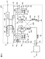
- FIG. 11 is a diagram showing a configuration of a directional coupler 201 according to the present embodiment.
- the directional coupler 201 further comprises filters 240 and 241 and termination circuits 260 and 261 as compared to the directional coupler 101 according to the second embodiment.
- the filter 240 is an example of the sixth filter, and is connected between one end 21 of the sub line 20 and the ground. One end of the filter 240 is connected to a path connecting one end 21 of the sub line 20 and the filter 30. The other end of the filter 240 is terminated. Specifically, the other end of the filter 240 is connected to the ground via the termination circuit 260.
- the filter 240 has a pass band different from the pass band of the filter 30. Specifically, the filter 240 passes a signal in the harmonic band of the target frequency detected by the detector 2.
- the pass band of the filter 240 and the pass band of the filter 30 are in a complementary relationship.
- the filter 240 is a filter having the same pass band as the filter 40, but is not limited to this.
- the filter 240 may be a band elimination filter 40E.
- the filter 240 may be a high-pass filter 40H.
- the filter 241 is an example of the fifth filter, and is connected between the other end 22 of the sub line 20 and the ground. One end of the filter 241 is connected to a path connecting the other end 22 of the sub line 20 and the filter 130. The other end of the filter 241 is terminated. Specifically, the other end of the filter 241 is connected to the ground via the termination circuit 261.
- the filter 241 has a pass band different from the pass band of the filter 130. Specifically, the filter 241 passes a signal in the harmonic band of the target frequency detected by the detector 2.
- the pass band of the filter 241 and the pass band of the filter 130 are in a complementary relationship.
- the filter 241 is a filter having the same pass band as the filter 140, but is not limited to this.
- the filter 241 may be a band elimination filter 40E.
- the filter 241 may be a high-pass filter 40H.
- the termination circuit 260 is connected to the other end of the filter 240.
- the impedance of the termination circuit 260 is adjusted to a predetermined value so that the signal passing through the filter 240 can be absorbed and consumed.
- the impedance of the terminal circuit 260 is adjusted to an appropriate value so as to absorb and consume the unnecessary wave signal 91 (see FIG. 12) flowing through the sub line 20 by electromagnetic coupling with the main line 10. ing.
- the termination circuit 261 is connected to the other end of the filter 241.
- the impedance of the termination circuit 261 is adjusted to a predetermined value so that the signal passing through the filter 241 can be absorbed and consumed.
- the impedance of the terminal circuit 261 is set to an appropriate value so as to absorb and consume the reflected wave unnecessary wave signal 91r (see FIG. 12) flowing through the sub line 20 by electromagnetic coupling with the main line 10. It has been adjusted.
- FIG. 12 is a diagram for explaining a signal flowing in the directional coupler 201 according to the present embodiment.
- the fundamental wave signal 90, the reflected wave fundamental wave signal 90r, and the distorted waves 92 to 95 are the same as those in the second embodiment. Therefore, the directional coupler 201 according to the present embodiment can improve the detection accuracy and suppress the occurrence of obstacles to the transmitter operation, as in the second embodiment.
- a filter 240 for passing a signal having a frequency different from the fundamental frequency f0 is connected to one end 21 of the sub line 20. Therefore, the unnecessary wave signal 91 passes through the filter 240 and is absorbed and consumed by the terminal circuit 260.
- a filter 241 for passing a signal having a frequency different from the fundamental frequency f0 is connected to the other end 22 of the sub line 20. Therefore, the reflected wave unnecessary wave signal 91r passes through the filter 241 and is absorbed and consumed by the terminal circuit 261.
- both the unnecessary wave signal 91 and the reflected wave unnecessary wave signal 91r are difficult to return to the sub line 20, so that they are suppressed from being mixed into the main line 10 via the sub line 20. Therefore, it is possible to suppress the occurrence of a failure in the transmitter operation.
- the directional coupler 201 includes a filter 241 having a pass band different from the pass band of the filter 130.
- One end of the filter 241 is connected to a path connecting the other end 22 of the sub line 20 and the filter 130, and the other end of the filter 241 is terminated.
- the directional coupler 201 further includes a filter 240 having a pass band different from the pass band of the filter 30.
- One end of the filter 240 is connected to a path connecting one end 21 of the sub line 20 and the filter 30, and the other end of the filter 240 is terminated.
- the directional coupler 201 may include only one of the filters 240 and 241.
- FIG. 13 is a diagram showing a modified example of the configuration of a plurality of filters included in the directional coupler 1, 101 or 201.
- FIG. 13 discloses an example in which each of the low-pass filter 30L, the band-pass filter 40B, and the high-pass filter 40H is connected to the node N3 (that is, the coupling output terminal 50).
- the bandpass filter 40B and the highpass filter 40H are examples of the second filter, respectively.
- the node N21, which is the other end of the bandpass filter 40B, is terminated. Specifically, the node N21 of the bandpass filter 40B is connected to the ground via the terminal circuit 60. Further, the node N22, which is the other end of the high-pass filter 40H, is also terminated. Specifically, the node N22 of the high-pass filter 40H is connected to the ground via the terminal circuit 61.
- the low-pass filter 30L, the band-pass filter 40B, and the high-pass filter 40H constitute, for example, a triplexer.
- the pass band of the low-pass filter 30L, the pass band of the band-pass filter 40B, and the pass band of the high-pass filter 40H have a complementary relationship with each other. That is, these three filters are configured so that the signal flowing from the node N3 toward the filter passes through one of the three filters and not the other two in the entire frequency band. There is.
- the impedances of the terminal circuits 60 and 61 are different from each other.
- the impedance of the terminal circuit 60 is adjusted so that a signal having a frequency of 2f0, which is a second harmonic of the fundamental frequency f0, can be appropriately absorbed and consumed.
- the impedance of the terminal circuit 61 is adjusted so that a signal having a frequency of 3f0, which is a third harmonic of the fundamental frequency f0, or a signal having a frequency higher than that can be appropriately absorbed and consumed.
- the impedance of the termination circuit 60 is adjusted so that the distortion signal 92 generated by the detector 2 can be appropriately absorbed and consumed, and the impedance of the termination circuit 61 appropriately matches the distortion signal 93 generated by the switch circuit 180. It may be adjusted so that it can be absorbed and consumed. Even when the frequencies of the distorted signals 92 and 93 are different, each of them can be appropriately absorbed and consumed.
- the directional coupler 1, 101 or 201 may include a plurality of filters 40.
- the filter configuration shown in FIG. 13 may be applied to the configurations of the filters 130 and 140 connected to the variable termination circuit 170 or the switch circuit 180. That is, the directional coupler 1, 101 or 201 may include a plurality of filters 140.
- the nodes N1 and N3 shown in FIG. 13 correspond to the nodes N4 and N6, respectively.
- the low-pass filter 30L is an example of the filter 130
- the band-pass filter 40B and the high-pass filter 40H are examples of the filter 140, respectively.
- the distortion signal generated on the other end 22 side of the sub line 20 is suppressed from returning to the main line 10, so that it is possible to suppress the occurrence of a failure in the transmitter operation.
- the combination of the three filters is not limited to the example shown in FIG.
- it may be three filters selected from a low-pass filter, a high-pass filter, a band-pass filter, and a band elimination filter.
- the three filters may include filters of the same type. Further, three or more terminated filters (second filter or fourth filter) may be provided.
- the directional coupler 1, 101 or 201 does not have to include the termination circuit 60.
- the filter 40 can be brought into a state equivalent to the termination of the other end of the filter 40.
- the directional coupler 101 or 201 may not include termination circuits 160, 260 or 261.
- the termination circuit 61 shown in FIG. 13 may not be provided.
- At least one of the low-pass filter 30L, the high-pass filter 40H, the band-pass filter 30B, and the band elimination filter 40E may be tuneable. That is, at least one of the low-pass filter 30L, the high-pass filter 40H, the band-pass filter 30B, and the band elimination filter 40E may have a changeable pass band.
- a switch or a varicap is used for tuning.
- the filter 30 may be composed only of an inductor connected in series between the node N1 and the node N3.
- the filter 40 may be composed of only a capacitor connected in series between the node N2 and the node N3.
- the filter 130 may consist only of an inductor connected in series between the node N4 and the node N6.
- the filter 140 may be composed of only a capacitor connected in series between the node N5 and the node N6.
- the directional coupler 1, 101 or 201 may include a detector 2.
- the directional coupler 1, 101 or 201 may include a plurality of main lines 10 or a plurality of sub lines 20.
- the plurality of sub-lines 20 may be electromagnetically coupled to one main line 10.
- the plurality of sub-lines 20 may be electromagnetically coupled to each of the plurality of main lines 10 on a one-to-one basis or a plurality of one-to-one basis.
- the directional coupler 1, 101 or 201 may include a line changeover switch for selecting a plurality of sub lines 20.
- the present invention can be widely used in electronic devices including directional couplers and communication devices.
Landscapes
- Transmitters (AREA)
Abstract
La présente invention concerne un coupleur directionnel (1) comprenant une ligne principale (10), une sous-ligne (20) couplée de manière électromagnétique à la ligne principale (10), une borne de sortie couplée (50) reliée à une extrémité (21) de la sous-ligne (20), un filtre (30) relié entre une extrémité (21) de la sous-ligne (20) et la borne de sortie couplée (50), et un filtre (40) ayant une bande passante supérieure à une bande passante du filtre (30). Une extrémité du filtre (40) est reliée à la borne de sortie couplée. L'autre extrémité du filtre (40) est terminée.
Priority Applications (1)
| Application Number | Priority Date | Filing Date | Title |
|---|---|---|---|
| US18/153,407 US12294133B2 (en) | 2020-07-21 | 2023-01-12 | Directional coupler |
Applications Claiming Priority (2)
| Application Number | Priority Date | Filing Date | Title |
|---|---|---|---|
| JP2020-124712 | 2020-07-21 | ||
| JP2020124712 | 2020-07-21 |
Related Child Applications (1)
| Application Number | Title | Priority Date | Filing Date |
|---|---|---|---|
| US18/153,407 Continuation US12294133B2 (en) | 2020-07-21 | 2023-01-12 | Directional coupler |
Publications (1)
| Publication Number | Publication Date |
|---|---|
| WO2022019178A1 true WO2022019178A1 (fr) | 2022-01-27 |
Family
ID=79728761
Family Applications (1)
| Application Number | Title | Priority Date | Filing Date |
|---|---|---|---|
| PCT/JP2021/026286 Ceased WO2022019178A1 (fr) | 2020-07-21 | 2021-07-13 | Coupleur directionnel |
Country Status (2)
| Country | Link |
|---|---|
| US (1) | US12294133B2 (fr) |
| WO (1) | WO2022019178A1 (fr) |
Citations (4)
| Publication number | Priority date | Publication date | Assignee | Title |
|---|---|---|---|---|
| US20170230066A1 (en) * | 2016-02-05 | 2017-08-10 | Skyworks Solutions, Inc. | Electromagnetic couplers with multi-band filtering |
| JP2018037780A (ja) * | 2016-08-30 | 2018-03-08 | 株式会社村田製作所 | 双方向性結合器 |
| JP2019062309A (ja) * | 2017-09-25 | 2019-04-18 | 株式会社村田製作所 | 方向性結合器及び通信ユニット |
| WO2019189232A1 (fr) * | 2018-03-28 | 2019-10-03 | 株式会社村田製作所 | Coupleur directionnel |
-
2021
- 2021-07-13 WO PCT/JP2021/026286 patent/WO2022019178A1/fr not_active Ceased
-
2023
- 2023-01-12 US US18/153,407 patent/US12294133B2/en active Active
Patent Citations (4)
| Publication number | Priority date | Publication date | Assignee | Title |
|---|---|---|---|---|
| US20170230066A1 (en) * | 2016-02-05 | 2017-08-10 | Skyworks Solutions, Inc. | Electromagnetic couplers with multi-band filtering |
| JP2018037780A (ja) * | 2016-08-30 | 2018-03-08 | 株式会社村田製作所 | 双方向性結合器 |
| JP2019062309A (ja) * | 2017-09-25 | 2019-04-18 | 株式会社村田製作所 | 方向性結合器及び通信ユニット |
| WO2019189232A1 (fr) * | 2018-03-28 | 2019-10-03 | 株式会社村田製作所 | Coupleur directionnel |
Also Published As
| Publication number | Publication date |
|---|---|
| US12294133B2 (en) | 2025-05-06 |
| US20230178870A1 (en) | 2023-06-08 |
Similar Documents
| Publication | Publication Date | Title |
|---|---|---|
| US7339445B2 (en) | BAW duplexer without phase shifter | |
| US11101839B2 (en) | High frequency filter, multiplexer, high frequency front-end circuit, and communication device | |
| JP5794365B2 (ja) | ケーブルおよび通信装置 | |
| US9106204B2 (en) | Four LC element balun | |
| JPWO2020054284A1 (ja) | マルチプレクサならびにそれを用いた高周波フロントエンド回路および通信装置 | |
| US11894621B2 (en) | Radio-frequency apparatus with multi-band balun with improved performance and associated methods | |
| US6952142B2 (en) | Frequency-selective balun transformer | |
| KR20190015128A (ko) | 복합형 필터 장치, 고주파 프론트 엔드 회로 및 통신 장치 | |
| SE544605C2 (en) | Compact balun with out-of-band spurious suppression | |
| US20170126197A1 (en) | Broadband matching circuit for capacitive device | |
| US20230077950A1 (en) | Filter device and multiplexer | |
| WO2018012275A1 (fr) | Multiplexeur, circuit de préamplificateur d'ondes haute fréquence, et terminal de communication | |
| CN113904082A (zh) | 双微带线耦合器、功率放大器及相关设备和芯片 | |
| KR20130028656A (ko) | 전자 부품 | |
| CN107852142A (zh) | 射频双工器 | |
| US12034464B2 (en) | Multiplexer, front end module, and communication device | |
| WO2022019178A1 (fr) | Coupleur directionnel | |
| JP2021106334A (ja) | 高周波回路 | |
| JP2012039444A (ja) | アイソレータ及び通信機器 | |
| CN113746445B (zh) | 定向耦合器 | |
| WO2021241050A1 (fr) | Coupleur directionnel | |
| US12068738B2 (en) | Configurable micro-acoustic RF filter | |
| WO2018061974A1 (fr) | Circuit frontal haute fréquence | |
| JP2021072563A (ja) | マルチプレクサ | |
| JPH1188011A (ja) | フィルタ装置及びフィルタを含む電子回路装置 |
Legal Events
| Date | Code | Title | Description |
|---|---|---|---|
| 121 | Ep: the epo has been informed by wipo that ep was designated in this application |
Ref document number: 21845471 Country of ref document: EP Kind code of ref document: A1 |
|
| NENP | Non-entry into the national phase |
Ref country code: DE |
|
| 122 | Ep: pct application non-entry in european phase |
Ref document number: 21845471 Country of ref document: EP Kind code of ref document: A1 |
|
| NENP | Non-entry into the national phase |
Ref country code: JP |