WO2022019206A1 - ノイズフィルタ - Google Patents
ノイズフィルタ Download PDFInfo
- Publication number
- WO2022019206A1 WO2022019206A1 PCT/JP2021/026596 JP2021026596W WO2022019206A1 WO 2022019206 A1 WO2022019206 A1 WO 2022019206A1 JP 2021026596 W JP2021026596 W JP 2021026596W WO 2022019206 A1 WO2022019206 A1 WO 2022019206A1
- Authority
- WO
- WIPO (PCT)
- Prior art keywords
- hole
- holding
- magnetic core
- noise filter
- bus bar
- Prior art date
- Legal status (The legal status is an assumption and is not a legal conclusion. Google has not performed a legal analysis and makes no representation as to the accuracy of the status listed.)
- Ceased
Links
Images







Classifications
-
- H—ELECTRICITY
- H03—ELECTRONIC CIRCUITRY
- H03H—IMPEDANCE NETWORKS, e.g. RESONANT CIRCUITS; RESONATORS
- H03H7/00—Multiple-port networks comprising only passive electrical elements as network components
- H03H7/01—Frequency selective two-port networks
- H03H7/09—Filters comprising mutual inductance
-
- H—ELECTRICITY
- H01—ELECTRIC ELEMENTS
- H01F—MAGNETS; INDUCTANCES; TRANSFORMERS; SELECTION OF MATERIALS FOR THEIR MAGNETIC PROPERTIES
- H01F17/00—Fixed inductances of the signal type
- H01F17/04—Fixed inductances of the signal type with magnetic core
- H01F17/06—Fixed inductances of the signal type with magnetic core with core substantially closed in itself, e.g. toroid
-
- H—ELECTRICITY
- H01—ELECTRIC ELEMENTS
- H01F—MAGNETS; INDUCTANCES; TRANSFORMERS; SELECTION OF MATERIALS FOR THEIR MAGNETIC PROPERTIES
- H01F27/00—Details of transformers or inductances, in general
- H01F27/28—Coils; Windings; Conductive connections
- H01F27/2847—Sheets; Strips
- H01F27/2852—Construction of conductive connections, of leads
-
- H—ELECTRICITY
- H01—ELECTRIC ELEMENTS
- H01F—MAGNETS; INDUCTANCES; TRANSFORMERS; SELECTION OF MATERIALS FOR THEIR MAGNETIC PROPERTIES
- H01F37/00—Fixed inductances not covered by group H01F17/00
-
- H—ELECTRICITY
- H03—ELECTRONIC CIRCUITRY
- H03H—IMPEDANCE NETWORKS, e.g. RESONANT CIRCUITS; RESONATORS
- H03H1/00—Constructional details of impedance networks whose electrical mode of operation is not specified or applicable to more than one type of network
- H03H1/0007—Constructional details of impedance networks whose electrical mode of operation is not specified or applicable to more than one type of network of radio frequency interference filters
-
- H—ELECTRICITY
- H01—ELECTRIC ELEMENTS
- H01F—MAGNETS; INDUCTANCES; TRANSFORMERS; SELECTION OF MATERIALS FOR THEIR MAGNETIC PROPERTIES
- H01F17/00—Fixed inductances of the signal type
- H01F17/04—Fixed inductances of the signal type with magnetic core
- H01F17/06—Fixed inductances of the signal type with magnetic core with core substantially closed in itself, e.g. toroid
- H01F2017/065—Core mounted around conductor to absorb noise, e.g. EMI filter
-
- H—ELECTRICITY
- H03—ELECTRONIC CIRCUITRY
- H03H—IMPEDANCE NETWORKS, e.g. RESONANT CIRCUITS; RESONATORS
- H03H1/00—Constructional details of impedance networks whose electrical mode of operation is not specified or applicable to more than one type of network
- H03H2001/0021—Constructional details
- H03H2001/005—Wound, ring or feed-through type inductor
-
- H—ELECTRICITY
- H03—ELECTRONIC CIRCUITRY
- H03H—IMPEDANCE NETWORKS, e.g. RESONANT CIRCUITS; RESONATORS
- H03H1/00—Constructional details of impedance networks whose electrical mode of operation is not specified or applicable to more than one type of network
- H03H2001/0021—Constructional details
- H03H2001/0057—Constructional details comprising magnetic material
Definitions
- This disclosure relates to a noise filter that suppresses noise radiated from a bus bar.
- Patent Document 1 describes a noise filter that takes measures against noise radiated from a conductive bus bar.
- the noise filter includes a magnetic core having a through hole, and is used by penetrating a bus bar through the through hole of the magnetic core.
- a bent bus bar may be used. Even if the bent-shaped bus bar is inserted into the through hole of the magnetic core, the bent portion of the bus bar may interfere with the opening edge of the through hole and may not be able to penetrate the through hole. In such a case, for example, by adopting a configuration in which the inner diameter of the through hole of the magnetic core is increased or a configuration in which the magnetic core is divided, the bent-shaped bus bar is penetrated through the through hole of the magnetic core. It is possible to make it. However, as the inner diameter of the through hole is increased, the impedance of the magnetic core is lowered, so that the noise reduction effect of the noise filter is lowered. Further, when the magnetic core has a divided structure, the magnetic permeability of the magnetic core is lowered, so that the noise reduction effect of the noise filter is lowered.
- the present disclosure preferably provides a noise filter that does not easily reduce the noise reduction effect while increasing the degree of freedom in the shape of the bus bar in the apparatus.
- the noise filter of one aspect of the present disclosure includes a non-divided magnetic core having a through hole having a first opening and a second opening at both ends, a first connection portion connectable to a bus bar, and a first connection portion. It has a second connecting portion at both ends, and includes a conductive connecting terminal arranged inside the through hole and a holding portion for holding the connecting terminal arranged inside the through hole. 1
- the connection portion is held by the holding portion on the magnetic core with the connection portion directed from the inside of the through hole toward the first opening side and the second connection portion directed from the inside of the through hole toward the second opening side. ing.
- a conductive connecting terminal having a first connecting portion and a second connecting portion that can be connected to the bus bar is arranged in the through hole of the magnetic core integrally formed.
- the first connection portion is directed from the inside of the through hole toward the first opening side
- the second connection portion is directed from the inside of the through hole toward the second opening side in the extending direction of the through hole. In the state, it is held in the through hole by the holding portion.
- the first bus bar of the set of bus bars is connected from the first opening side of the through hole to the first connection portion
- the second bus bar is connected from the second opening side of the through hole.
- the signal flowing through the first bus bar can be passed through the through hole of the magnetic core and sent to the second bus bar regardless of the bent shape of the bus bar.
- the noise filter in one aspect of the present disclosure contains a magnetic core and includes a case made of a non-conductive resin.
- the case has a tubular through portion and is magnetic in a state where the through hole is penetrated by the through portion. It houses the body core and the connecting terminals may be located inside the penetration.
- the holding portion has an accommodating portion arranged inside the through hole, and the connecting terminal may be held by accommodating the connecting terminal by the accommodating portion.
- the connecting terminal can be held in the through hole while maintaining the insulation between the connecting terminal and the magnetic core, so that the noise of the noise filter can be properly transmitted between the bus bars. It is possible to make it difficult to reduce the reduction effect.
- the holding portion is arranged inside the through hole, and may have a locking portion for locking the holding portion to the magnetic core.
- the connecting terminal can be reliably positioned in the through hole of the magnetic core by increasing the fixing force of the holding portion to the magnetic core. Therefore, for example, an external force is applied to the connecting terminal via the bus bar. Even in this case, it is possible to prevent the connecting terminal from being pulled out from the through hole of the magnetic core, and to prevent the noise reduction effect of the noise filter from being reduced.
- a case containing a magnetic core and made of a non-conductive resin is provided, and a holding portion may be arranged inside a through hole and integrally formed with the case.
- FIG. 3 is a cross-sectional view of the first lid portion in a plane parallel to the second direction and the third direction.
- FIG. 3 is a cross-sectional view of a second lid portion in a plane parallel to the second direction and the third direction. The figure explaining the connection terminal. The figure explaining the connection terminal.
- the perspective view of the noise filter which concerns on 2nd Embodiment. Sectional drawing of the noise filter in the plane parallel to the 1st direction and the 3rd direction. Sectional drawing of the noise filter in the plane parallel to the 1st direction and the 2nd direction.
- the direction in which the through hole of the magnetic core extends is defined as the first direction
- the directions orthogonal to the first direction are defined as the second direction and the third direction, respectively.
- each of these directions is merely a direction defined for briefly explaining the relative positional relationship of each part constituting the noise filter.
- the direction in which the noise filter is directed is arbitrary.
- the noise filter is in a state where the third direction shown in the figure does not match the vertical direction due to gravity. May be used.
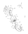
- the noise filter 10 shown in FIGS. 1 and 2 is a device connected to the bus bars 101, 102, 103, 104 and suppressing the radiation of noise from the bus bars 101 to 104. Specifically, the noise filter 10 connects a set of bus bars 101 and 102, and relays a signal flowing from a circuit (not shown) to the bus bar 101 to the bus bar 102 while passing through a through hole of the magnetic core 20. .. The noise filter 10 connects a set of bus bars 103 and 104, and relays a signal flowing from a circuit (not shown) to the bus bar 103 to the bus bar 104 while passing through a through hole of the magnetic core 20.
- the bus bars 101 to 104 are formed with a mounting seat portion, an extension portion, and an insertion portion by bending a flat plate piece.
- the mounting seat portions 101a, 102a, 103a, 104a are portions where through holes are formed.
- the through hole is a portion through which the terminal fixing bolt for fixing the bus bars 101 to 104 to the device penetrates.
- the mounting seats 101a to 104a have planes parallel to the plane defined by the first direction D1 and the second direction D2.
- the extending portions 101b, 102b, 103b, and 104b are portions of the bus bars 101 to 104 that connect the mounting seat portions 101a to 104a and the insertion portions 101c to 104c.
- the extending portions 101b to 104b are portions bent in a predetermined direction with respect to the mounting seat portions 101a to 104a and the insertion portions 101c to 104c.
- the insertion portions 101c, 102c, 103c, 104c are portions connected to the connection terminals 40, 50 included in the noise filter 10.
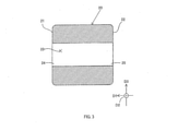
- FIG. 3 is a cross-sectional view of the magnetic core 20 in a plane along the first direction D1.
- the magnetic core 20 is a non-divided type and has a ring shape having end faces 21 and 22.
- a through hole 23 is formed in the magnetic core 20.
- the through hole 23 is a through hole extending from the opening 24 formed in the first end surface 21 of the magnetic core 20 to the opening 25 formed in the second end surface 22.
- a soft ferrite which is a soft magnetic material, a nanocrystalline soft magnetic material whose main component is a fine metal, or the like can be used.
- the nanocrystal soft magnetic material for example, Finemet (registered trademark) can be used.
- the holding portion 60 is a member that holds the connecting terminals 40 and 50 inside the through hole 23 of the magnetic core 20.
- the holding portion 60 has an accommodating portion 61 accommodating the connecting terminals 40 and 50, and a set of locking portions 65a and 65b.
- the accommodating portion 61 is a container in which the connecting terminals 40 and 50 are arranged side by side along the second direction D2. Specifically, an accommodation space 611 for accommodating the connecting terminal 40 and an accommodating space 612 for accommodating the connecting terminal 50 are formed inside the accommodating portion 61. As shown in FIG. 6, the accommodation space 611 extends from the opening 613 formed at the first end of the first direction D1 to the opening 615 formed at the second end in the accommodation portion 61. It extends and exists. As shown in FIG. 6, the accommodation space 612 extends from the opening 614 formed at the first end of the first direction D1 to the opening 616 formed at the second end in the accommodation portion 61. It extends and exists.
- the accommodating portion 61 includes a container main body 62, a first lid portion 63, and a second lid portion 64.
- the accommodating portion 61 is configured by assembling the container main body 62, the first lid portion 63, and the second lid portion 64.
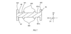
- FIG. 7 is a cross-sectional view of the container body 62 in a plane parallel to the second direction D2 and the third direction D3.
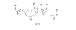
- FIG. 8 is a cross-sectional view of the first lid portion 63 in a plane parallel to the second direction D2 and the third direction D3.
- FIG. 9 is a cross-sectional view of the second lid portion 64 in a plane parallel to the second direction D2 and the third direction D3.
- the container main body 62 has a partition wall portion 621 which is a rectangular wall, and side wall portions 622 and 623 provided at both ends of the third direction D3 in the partition wall portion 621. .. Specifically, the side wall portions 622 and 623 extend from both ends of the third direction D3 of the partition wall portion 621 to the second direction D2, and are planes defined by the second direction D2 and the third direction D3.
- the cross section is substantially H-shaped. That is, as shown in FIG. 7, the container body 62 is formed with a first recess 66 having a bottom surface 621a as the first surface of the partition wall portion 621 in the third direction D3.
- the container body 62 is formed with a second recess 67 having a bottom surface 621b as a second surface of the partition wall portion 621 in the third direction D3.
- the bottom surface 621a of the partition wall portion 621 is provided with a holding protrusion 625 protruding in the second direction D2, and the bottom surface 621b is provided with a holding protrusion 626 protruding in the second direction D2.
- the container body 62 is non-conductive and is formed of, for example, a polyamide resin or the like.
- the first lid portion 63 has a rectangular base portion 631 and side wall portions 632 and 633 extending at both ends of the third direction D3 in the base portion 631.
- a holding protrusion 635 protruding in the second direction D2 is provided.
- the first lid portion 63 is non-conductive and is formed of, for example, a polyamide resin or the like.
- a flange 634 protruding outward from the base portion 631 and the side wall portions 632 and 633 is formed at the end of the first lid portion 63 in the first direction D1.
- the second lid portion 64 has a rectangular base portion 641 and side wall portions 642, 643 extending at both ends of the third direction D3 in the base portion 641.
- a holding protrusion 645 protruding in the second direction D2 is provided on the back surface of the base 641 facing the container body 62.
- a flange 644 protruding outward from the base portion 641 and the side wall portions 642 and 643 is formed at the end of the first direction D1 in the second lid portion 64.
- the second lid portion 64 is non-conductive and is formed of, for example, a polyamide resin or the like.
- the locking portion 65a is formed at the end of the first lid portion 63 in the first direction D1.
- the locking portion 65b is formed at the end portion of the second lid portion 64 in the first direction D1.
- the locking portions 65a and 65b are formed in the first and second lid portions 63 and 64 at the end opposite to the end of the first direction D1 in which the flanges 634 and 644 are formed. ..
- the locking portions 65a and 65b are formed by cutting out the edges of the base portions 631 and 641 in the first direction D1 and are configured as claw portions having elasticity in the second direction D2.
- the connecting terminals 40 and 50 are terminals capable of connecting the bus bars 101 to 104 by inserting the insertion portions 101c to 104c of the bus bars 101 to 104.
- the insertion portions 101c and 102c of the bus bars 101 and 102 are inserted into the connecting terminal 40, and the insertion portions 103c and 104c of the bus bars 103 and 104 are inserted into the connecting terminal 50.
- the connecting terminals 40 and 50 are formed of a conductive member such as copper, and an elastic material such as phosphor bronze is particularly preferable.
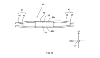
- the connecting terminal 40 has a first connecting portion 41, a second connecting portion 42, and a held portion 43.
- the held portion 43 is a rectangular parallelepiped portion that is located between the first connecting portion 41 and the second connecting portion 42 and opens in the first direction D1.
- the held portion 43 has holding surfaces 43a and 43b which are parallel surfaces facing the second direction D2.
- a holding hole 48 is formed in the holding surface 43a
- a holding hole 49 is formed in the holding surface 43b.
- the holding holes 48 and 49 are shown by broken lines.
- the first connection portion 41 includes three pairs of elastic pieces 44, 45.
- the elastic pieces 44 and 45 extend from the first edge of the held portion 43 in the first direction D1 and grip the bus bar 103 in cooperation with each other.
- the elastic pieces 44 and 45 have a thin plate shape and have elasticity in the direction of gripping the bus bar 103 (that is, the second direction D2).
- the elastic piece 44 extends from the first edge of the holding surface 43a
- the elastic piece 45 extends from the first edge of the holding surface 43b
- the elastic piece 45 and the elastic piece 46 are paired. Grasp the bus bar.
- three pairs of elastic pieces 44, 45 are provided from the held portion 43 side by side in the third direction D3.
- the second connecting portion 42 includes three pairs of elastic pieces 46 and 47.
- the elastic pieces 46 and 47 extend from the second edge of the held portion 43 in the first direction D1 and grip the bus bar 104 in cooperation with each other.
- the elastic pieces 46 and 47 have a thin plate shape and have elasticity in the direction of gripping the bus bar 104 (that is, the second direction D2).
- the elastic piece 46 extends from the second edge of the holding surface 43a
- the elastic piece 47 extends from the second edge of the holding surface 43b
- the elastic piece 46 and the elastic piece 47 are paired. , Grasp the bus bar.
- three pairs of elastic pieces 46, 47 are provided on the held portion 43 side by side in the third direction D3.
- the connecting terminal 50 has a first connecting portion 51, a second connecting portion 52, and a held portion 53.
- the connecting terminal 50 has the same shape as the connecting terminal 40. That is, the held portion 53 is a rectangular parallelepiped portion that is located between the first connecting portion 51 and the second connecting portion 52 and opens in the first direction D1.
- the held portion 53 has holding surfaces 53a and 53b which are parallel surfaces facing the second direction D2.
- a holding hole 58 is formed in the holding surface 53a
- a holding hole 59 is formed in the holding surface 53b.
- the holding holes 58 and 59 are shown by broken lines.
- the first connection portion 51 includes three pairs of elastic pieces 54 and 55.
- the elastic pieces 54 and 55 extend from the first edge of the held portion 53 in the first direction D1 and grip the bus bar 101 in cooperation with each other.
- the elastic pieces 54 and 55 have a thin plate shape and have elasticity in the direction of gripping the bus bar 101 (that is, the second direction D2).
- the elastic piece 54 extends from the first edge of the holding surface 53a
- the elastic piece 55 extends from the first edge of the holding surface 53b
- the elastic piece 55 and the elastic piece 56 are paired. , Grasp the bus bar.
- three pairs of elastic pieces 54 and 55 are extended from the held portion 53 side by side in the third direction D3.
- the second connecting portion 52 includes three pairs of elastic pieces 56 and 57.
- the elastic pieces 56, 57 extend from the second edge in the first direction D1 of the held portion 53, and are composed of the elastic pieces 56, 57 that jointly grip the bus bar 102.
- the elastic pieces 56 and 57 have a thin plate shape and have elasticity in the direction of gripping the bus bar 102 (that is, the second direction D2).
- the elastic piece 56 extends from the second edge of the holding surface 53a
- the elastic piece 57 extends from the second edge of the holding surface 53b
- the elastic piece 56 and the elastic piece 57 are paired. , Grasp the bus bar.
- three pairs of elastic pieces 56, 57 are extended from the held portion 53 side by side in the third direction D3.
- the first lid portion 63 is fitted to the opening side of the first recess 66 of the container body 62.
- the inside of the first recess 66 and the back surface of the first lid 63 form an accommodation space 611 in which the connecting terminal 40 is accommodated.
- the holding protrusion 625 of the container body 62 is inserted into the holding hole 49 of the held portion 43, and the holding protrusion 635 of the first lid portion 63 is inserted into the holding hole 48 of the held portion 43. Will be inserted.
- the connecting terminal 40 accommodates the accommodating portion 61 in a state where the first connecting portion 41 faces the opening 613 side and the second connecting portion 42 faces the opening 615 side in the first direction D1. It is held in space 611. Further, the connecting terminal 40 is held in the accommodation space 611 in a state where the movement in the first direction D1 is restricted by the holding protrusions 625 and 635 protruding in the second direction D2.
- the second lid portion 64 is fitted to the opening side of the second concave portion 67 of the container main body 62 in a state where the connecting terminal 50 is accommodated in the second concave portion 67 of the container main body 62.
- the inside of the second recess 67 and the back surface of the second lid portion 64 form an accommodation space 612 in which the connecting terminal 50 is accommodated.
- the holding protrusion 626 of the container body 62 is inserted into the holding hole 59 of the held portion 53, and the holding protrusion 645 of the second lid portion 64 is inserted into the holding hole 58 of the held portion 53. Will be inserted.
- the connecting terminal 50 is accommodated in the accommodating portion 61 in a state where the first connecting portion 51 faces the opening 614 side and the second connecting portion 52 faces the opening 616 side in the first direction D1. It is held in space 612. Further, the connecting terminal 50 is held in the accommodation space 612 in a state where the movement in the first direction D1 is restricted by the holding protrusions 626 and 645 protruding in the second direction D2.
- the accommodating portion 61 is inserted into the through hole 23 of the magnetic core 20 from the side where the locking portion 65 is formed.
- the locking portion 65 that has passed through the through hole 23 is hooked on the edge of the opening 24 of the through hole 23, so that the accommodating portion 61 is locked to the magnetic core 20. That is, the locking portion 65 ensures that the accommodating portion 61 is held in the through hole 23 of the magnetic core 20.
- the flanges 634 and 644 of the accommodating portion 61 abut against the edge of the opening 25 of the magnetic core 20, thereby restricting the insertion of the accommodating portion 61.
- the insertion portion 101c of the bus bar 101 is inserted from the opening 613 of the accommodation portion 61 between the elastic pieces 44 and 45 of the first connection portion 41, and the insertion portion 102c of the bus bar 102 is inserted from the opening 615 of the accommodation portion 61. , Inserted between the elastic pieces 46, 47 of the second connecting portion 42. As a result, the bus bar 101 and the bus bar 102 are connected by the connecting terminal 40 arranged in the through hole 23 of the magnetic core 20.
- the insertion portion 103c of the bus bar 103 is inserted from the opening 614 of the accommodation portion 61 between the elastic pieces 54 and 55 of the first connection portion 51, and the insertion portion 102c of the bus bar 104 is inserted from the opening 616 of the accommodation portion 61. , Inserted between the elastic pieces 56, 57 of the second connecting portion 52. As a result, the bus bar 103 and the bus bar 104 are connected by the connecting terminal 50 arranged in the through hole 23 of the magnetic core 20.
- the bus bars 101 to 104 can be slightly moved with the displacement of the elastic pieces even in the direction gripped by the elastic pieces 44 to 47, 54 to 57 (that is, the second direction D2). As a result, a slight positional deviation occurs between the bus bars 101 and 103 on the side gripped by the first connecting portions 41 and 51 and the bus bars 102 and 104 gripped by the second connecting portions 42 and 52. Even in this case, the bus bars can be connected in a state of absorbing this deviation.
- the first connecting portions 41 and 51 are directed from the inside of the through hole 23 of the magnetic core 20 toward the first opening, and the second connecting portions 42 and 52 are directed from the inside of the through hole 23.
- a holding portion 60 for holding the connecting terminals 40 and 50 in the through hole 23 while facing the opening of 2 is provided.
- the first bus bar is connected by the first connection portion 41 exposed from the first opening of the through hole 23 of the magnetic core 20, and the second bus bar is connected to the through hole 23. It can be connected by the second connecting portion 42 exposed from the second opening of the above. Therefore, both bus bars can be electrically connected. Therefore, regardless of the bent shape of the bus bar, the signal flowing through the first bus bar can be passed through the through hole 23 of the magnetic core 20 and sent to the second bus bar. As a result, it is possible to increase the degree of freedom in the shape of the bus bar in the apparatus and make it difficult to reduce the noise reduction effect of the noise filter 10.
- the holding portion 60 of the noise filter 10 has an accommodating portion 61 arranged inside the through hole 23, and the accommodating portion 61 accommodates the connecting terminals 40 and 50 so that the connecting terminals 40 and 50 are made of a magnetic material. It is held in the core 20.
- the connecting terminals can be held in the through holes while maintaining the insulating properties between the connecting terminals 40 and 50 and the magnetic core 20. Therefore, it is possible to make it difficult to reduce the noise reduction effect of the noise filter 10 while properly transmitting signals between the bus bars.
- the holding portion 60 is arranged inside the through hole 23, and has a locking portion 65 for locking the holding portion 60 to the magnetic core 20.
- the connecting terminals 40 and 50 can be reliably positioned on the magnetic core 20 by increasing the fixing force of the holding portion 60 to the magnetic core. For example, even when an external force is applied to the connecting terminals 40 and 50 via the bus bar, it is possible to prevent the connecting terminals 40 and 50 from being pulled out of the through hole 23 of the magnetic core 20 and to prevent the noise filter 10 from being pulled out. It is possible to suppress the reduction of the noise reduction effect.
- the connecting terminals 40 and 50 have holding holes formed in the held portions 43 and 53, and the accommodating portion 61 has a holding protrusion to be inserted into the holding holes.
- the connecting terminals 40 and 50 may have holding protrusions at the held portions 43 and 53, and the accommodating portion 61 may have holding holes.
- the holding portion 60 includes locking portions 65a and 65b. Instead, the holding portion 60 does not have to include the locking portion 65. Further, the holding portion 60 may be configured to include one locking portion instead of including the two locking portions 65a and 65b.
- the noise filter 10 includes a case 70 that houses the magnetic core 20. Further, the holding portion for holding the connecting terminal is integrally formed with the case 70.
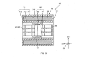
- FIG. 13 is a cross-sectional view of the noise filter 10 according to the present embodiment in a plane parallel to the first direction D1
- FIG. 14 is a plane parallel to the second direction D2 in the noise filter 10 according to the present embodiment. It is a cross-sectional view of.
- the case 70 includes a case main body 71 and a lid portion 72.
- the case 70 is made of a non-conductive resin, and for example, a polyamide resin can be used as a material.
- the case body 71 has an outer cylinder portion 711, a through cylinder portion 712, a bottom surface 713, and a partition wall 714.
- the outer tubular portion 711 is a tubular portion extending from the first surface of the bottom surface 713 in the first direction D1.
- the end of the outer cylinder portion 711 opposite to the bottom surface 713 is open.
- the through-cylinder portion 712 is a tubular portion extending in the same direction as the extension direction of the outer cylinder portion 711 from the first surface of the bottom surface 713 inside the outer cylinder portion 711. Specifically, the outer diameter dimension of the through cylinder portion 712 is smaller than the outer diameter dimension of the outer cylinder portion 711. As a result, a storage space 715 in which the magnetic core 20 is housed is formed between the inner peripheral surface of the outer cylinder portion 711 and the outer peripheral surface of the through cylinder portion 712.
- the partition wall 714 is a plate-shaped portion extending so as to partition the inside of the through-cylinder portion 712. As a result, two terminal accommodating spaces separated by a partition wall 714 are formed inside the through-cylinder portion 712.
- the lid portion 72 is an annular member having an opening in the center.
- the lid portion 72 is attached to the case body 71 so as to cover the opening of the accommodation space 715 formed between the outer cylinder portion 711 and the through cylinder portion 712 at the end of the case body 71 opposite to the bottom surface 713. Has been done.
- the holding portion 160 is integrally formed in the case 70.
- the holding portion 160 is provided in each of the two terminal accommodating spaces separated by the partition wall 714 inside the through cylinder portion 712.
- the holding portion 160 has an extending piece 161 and a locking piece 162.
- the extension piece 161 is a piece-shaped portion extending inward from the inner peripheral surface of the through-cylinder portion 712.
- the locking piece 162 extends from the extending piece 161 in the first direction D1 and has a claw-shaped tip.
- the locking piece 162 protrudes from the position on the inner peripheral surface side by a predetermined dimension in the third direction D3 from the tip of the extending piece 161.
- the held portions 43 and 53 of the connecting terminals 40 and 50 can be sandwiched between the tip of the locking piece 162 and the tip of the extending piece 161.
- the magnetic core 20 is accommodated in the accommodation space 715 in the case 70 in a state of being penetrated through the through hole 23 by the through cylinder portion 712.
- the connecting terminals 40 and 50 are accommodated in a state of being held by the holding portion 160 in each of the two terminal accommodating spaces partitioned by the partition wall 714 inside the through-cylinder portion 712.
- the connecting terminals 40 and 50 are held by the holding portion 160 on the magnetic core 20 with the connecting portions 41, 42, 51 and 52 facing each of the first directions D1.
- the penetrating cylinder portion 712 is an example of the penetrating portion.
- the noise filter 10 includes a case 70 containing a magnetic core 20 and made of a non-conductive resin, and the case 70 has a tubular through-cylinder portion 712.
- the magnetic core 20 is housed in a state where the through hole 23 of the magnetic core 20 is penetrated by the through cylinder portion 712.
- the connecting terminals 40 and 50 are arranged inside the through-cylinder portion 712.
- the noise filter 10 provided with the case 70 can have the same effect as that of the first embodiment.
- the holding portion 160 is arranged inside the through hole 23 of the magnetic core 20, and is integrally formed with the case 70.
- the holding portion 160 integrally formed with the case 70 has an extending piece 161 and a locking piece 162.
- the connecting terminals 40 and 50 arranged inside the through-cylinder portion 712 are held in a state where the holding protrusion portion of the holding member is inserted into the holding hole formed in the held portion.
- the holding portion 160 holds the connecting terminals 40 and 50 inside the through hole 23 of the magnetic core 20.
- the holding portion 160 may be integrally formed with the case 70 and may be configured to hold the connecting terminals 40 and 50 from the outside of the through hole 23.
- the two connecting terminals 40 and 50 are held by the holding portion 60 in the through hole 23 of the magnetic core 20.
- one connecting terminal may be held by the holding portion 60 in the through hole 23 of the magnetic core 20.
- the first and second connecting portions 41, 42, 51, 52 of the connecting terminals 40 and 50 are composed of a pair of elastic pieces that grip both sides of the bus bar.
- the first and second connection portions 41, 42, 51, and 52 need only be able to hold the insertion portion of the bus bar, and are not limited to the pair of elastic pieces described above.
- the first and second connection portions 41, 42, 51, 52 may be configured by an insertion groove for holding the insertion portion of the bus bar by inserting the insertion portion of the bus bar.
Landscapes
- Engineering & Computer Science (AREA)
- Power Engineering (AREA)
- Microelectronics & Electronic Packaging (AREA)
- Coils Or Transformers For Communication (AREA)
- Filters And Equalizers (AREA)
Abstract
ノイズフィルタを提供する。本開示のノイズフィルタは、両端に第1の開口部及び第2の開口部を有する貫通孔が形成された非分割型の磁性体コアと、バスバーに接続可能な第1接続部及び第2接続部を両端に有し、前記貫通孔の内部に配置された導電性の連結端子と、前記貫通孔の内部に配置された前記連結端子を保持する保持部と、を備え、前記連結端子は、前記第1接続部を前記貫通孔の内部から第1の開口部側に向け、かつ前記第2接続部を前記貫通孔の内部から第2の開口部側に向けた状態で、前記保持部により前記磁性体コアに保持されている。
Description
本国際出願は、2020年7月21日に日本国特許庁に出願された日本国特許出願第2020-124449号に基づく優先権を主張するものであり、日本国特許出願第2020-124449号の全内容を本国際出願に参照により援用する。
本開示 は、バスバーから輻射されるノイズを抑制するノイズフィルタに関する。
特許文献1には、導電性のバスバーから輻射されるノイズを対策するノイズフィルタが記載されている。ノイズフィルタは、貫通孔を有する磁性体コアを備えており、バスバーを磁性体コアの貫通孔に貫通させて使用される。
装置内でのバスバーの取り回しを考慮して、屈曲形状のバスバーを使用する場合がある。屈曲形状のバスバーは、磁性体コアの貫通孔に挿入させようとしても、バスバーにおける屈曲する部位が貫通孔の開口縁部に干渉し、貫通孔を貫通させることができない場合がある。このような場合、例えば、磁性体コアの貫通孔の内径寸法を大きくした構成や、磁性体コアを分割構造とした構成を採用することにより、屈曲形状のバスバーを磁性体コアの貫通孔に貫通させることが考えられる。しかし、貫通孔の内径寸法を大きくするほど、磁性体コアのインピーダンスが低下するため、ノイズフィルタのノイズ低減効果が低くなる。また、磁性体コアを分割構造とした場合、磁性体コアの透磁率が低下するため、ノイズフィルタのノイズ低減効果が低くなる。
本開示 は、装置内でのバスバー形状の自由度を高めつつ、ノイズ低減効果を低下させにくいノイズフィルタを提供することが好ましい。
本開示の一局面のノイズフィルタは、両端に第1の開口部及び第2の開口部を有する貫通孔が形成された非分割型の磁性体コアと、バスバーに接続可能な第1接続部及び第2接続部を両端に有し、貫通孔の内部に配置された導電性の連結端子と、貫通孔の内部に配置された連結端子を保持する保持部と、を備え、連結端子は、第1接続部を貫通孔の内部から第1の開口部側に向け、かつ第2接続部を貫通孔の内部から第2の開口部側に向けた状態で、保持部により磁性体コアに保持されている。
上記構成では、一体で形成された磁性体コアの貫通孔には、バスバーと接続可能な第1接続部及び第2接続部を両端に有する導電性の連結端子が配置されている。連結端子は、貫通孔の延びる方向において、第1接続部を貫通孔の内部から第1の開口部側に向け、かつ第2接続部を貫通孔の内部から第2の開口部側に向けた状態で、保持部により貫通孔内に保持されている。これにより、1組のバスバーのうち、第1のバスバーを、貫通孔の第1の開口部側から第1接続部に接続し、第2のバスバーを、貫通孔の第2の開口部側から第2接続部に接続することで、両バスバーを連結させることができる。そのため、非分割型の磁性体コアを用いる場合でも、バスバーの屈曲形状に関わらず、第1のバスバーを流れる信号を磁性体コアの貫通孔を通過させて第2のバスバーに流すことができる。その結果、装置内でのバスバーの形状の自由度を高めつつ、ノイズフィルタにおけるノイズ低減効果を低下させにくくすることができる。
本開示 の一局面のノイズフィルタは、磁性体コアを収容し、非導電性樹脂からなるケースを備え、ケースは、筒形状の貫通部を有し、貫通部により貫通孔を貫通した状態で磁性体コアを収容しており、連結端子は、貫通部の内部に配置されていてもよい。
本開示 の一局面のノイズフィルタでは、保持部は、貫通孔の内部に配置された収容部を有し、収容部により連結端子を収容することで連結端子が保持されていてもよい。これにより、連結端子と磁性体コアとの絶縁性を保った状態で、連結端子を貫通孔内で保持することができるため、バスバー間での信号の伝達を適正に行いつつ、ノイズフィルタのノイズ低減効果を低下させにくくすることができる。
本開示 の一局面のノイズフィルタでは、保持部は、貫通孔の内部に配置されており、当該保持部を磁性体コアに係止させる係止部を有していてもよい。これにより、磁性体コアに対する保持部の固定力を高めることにより、連結端子を磁性体コアの貫通孔に確実に位置決めすることができるため、例えば、バスバーを介して外力が連結端子に加えられた場合でも、連結端子が磁性体コアの貫通孔から外に引き出されてしまうのを抑制し、ノイズフィルタのノイズ低減効果が低下することを抑制することができる。
本開示 の一局面では、磁性体コアを収容し、非導電性樹脂からなるケースを備え、保持部は、貫通孔の内部に配置されており、かつケースに一体で形成されていてもよい。これにより、ケースを備えるノイズフィルタにおいて、本開示 の効果を奏しつつ、部品点数の増加を抑制することができる。
本開示 によれば、装置内でのバスバー形状の自由度を高めつつ、ノイズフィルタのノイズ低減効果を低下させにくいノイズフィルタを提供することができる。
10…ノイズフィルタ、20…磁性体コア、40,50…連結端子、41…第1接続部、42…第2接続部、60…保持部、101,102,103,104…バスバー、613,614,615,616…開口部
以下、ノイズフィルタの実施形態について、図面を参照しながら説明する。なお、以下の説明においては、必要に応じて図中に併記した各方向を利用して説明を行う。具体的には、磁性体コアの貫通孔が延びる方向を第1方向とし、この第1方向に直交する方向を、おのおの第2方向、第3方向とする。ただし、これらの各方向は、ノイズフィルタを構成する各部の相対的な位置関係を簡潔に説明するために規定した方向にすぎない。実際にノイズフィルタを利用するに当たって、ノイズフィルタがどのような方向に向けられるかは任意であり、例えば、図中に示す第3方向が重力との関係で鉛直方向とは一致しない状態でノイズフィルタが使用されてもよい。
[1.第1実施形態]
[1-1.構成]
図1及び図2に示すノイズフィルタ10は、バスバー101,102,103,104に接続され、バスバー101~104からのノイズの輻射を抑制する装置である。具体的には、ノイズフィルタ10は、1組のバスバー101,102を連結し、不図示の回路からバスバー101に流れる信号を、磁性体コア20の貫通孔を通過させつつ、バスバー102に中継する。ノイズフィルタ10は、1組のバスバー103,104を連結し、不図示の回路からバスバー103に流れる信号を、磁性体コア20の貫通孔を通過させつつバスバー104に中継する。
[1-1.構成]
図1及び図2に示すノイズフィルタ10は、バスバー101,102,103,104に接続され、バスバー101~104からのノイズの輻射を抑制する装置である。具体的には、ノイズフィルタ10は、1組のバスバー101,102を連結し、不図示の回路からバスバー101に流れる信号を、磁性体コア20の貫通孔を通過させつつ、バスバー102に中継する。ノイズフィルタ10は、1組のバスバー103,104を連結し、不図示の回路からバスバー103に流れる信号を、磁性体コア20の貫通孔を通過させつつバスバー104に中継する。
本実施形態では、バスバー101~104は、平板片を屈曲させることにより、取付座部、延設部、及び挿入部が形成されている。取付座部101a,102a,103a,104aは、貫通穴が形成される部位である。貫通穴は、バスバー101~104を、装置に固定するための端子固定用ボルトが貫通する部位である。本実施形態では、取付座部101a~104aは、第1方向D1と第2方向D2とで規定される平面に平行な面を有している。延設部101b,102b,103b,104bは、各バスバー101~104において、取付座部101a~104aと、挿入部101c~104cとを繋ぐ部位である。本実施形態では、延設部101b~104bは、取付座部101a~104a及び挿入部101c~104cに対して所定方向に屈曲した部位である。挿入部101c,102c,103c,104cは、ノイズフィルタ10が備える連結端子40,50に接続される部位である。
ノイズフィルタ10は、上述した磁性体コア20に加えて、連結端子40,50と、保持部60とを備えている。図3は、第1方向D1に沿った面での磁性体コア20の断面図である。磁性体コア20は、非分割型であり、端面21,22を有する環形状である。磁性体コア20には、貫通孔23が形成されている。貫通孔23は、磁性体コア20の第1の端面21に形成された開口部24から、第2の端面22に形成された開口部25まで延びた貫通穴である。磁性体コア20は、軟磁性材料であるソフトフェライト、又は微細な金属を主成分とするナノ結晶軟磁性材料等を用いることができる。ナノ結晶軟磁性材料として、例えば、ファインメット(登録商標)を用いることができる。
次に、保持部60の構成を説明する。図4,図5,図6に示すように、保持部60は、連結端子40,50を、磁性体コア20の貫通孔23の内部で保持する部材である。保持部60は、連結端子40,50を収容する収容部61と、1組の係止部65a,65bとを有している。
収容部61は、連結端子40,50を第2方向D2に沿って並んだ状態で収容する容器である。具体的には、収容部61の内部には、連結端子40を収容する収容空間611と、連結端子50を収容する収容空間612とが形成されている。図6に示すように、収容空間611は、収容部61内において、第1方向D1の第1の端部に形成された開口部613から、第2の端部に形成された開口部615まで延びて存在している。図6に示すように、収容空間612は、収容部61内において、第1方向D1の第1の端部に形成された開口部614から、第2の端部に形成された開口部616まで延びて存在している。
本実施形態では、収容部61は、容器本体62と、第1蓋部63と、第2蓋部64とを備える。収容部61は、容器本体62と、第1蓋部63と、第2蓋部64とを組み付けて構成される。図7は、第2方向D2及び第3方向D3に平行な面での容器本体62の断面図である。図8は、第2方向D2及び第3方向D3に平行な面での第1蓋部63の断面図である。図9は、第2方向D2及び第3方向D3に平行な面での第2蓋部64の断面図である。
容器本体62は、図5に示すように、矩形状の壁である間仕切り壁部621と、間仕切り壁部621における第3方向D3の両端に設けられた側壁部622,623とを有している。具体的には、側壁部622,623は、間仕切り壁部621の第3方向D3の両端から、第2方向D2に延設されており、第2方向D2及び第3方向D3で規定される平面での断面が略H状となっている。すなわち、図7に示すように、容器本体62には、間仕切り壁部621の第3方向D3での第1の面を底面621aとする第1凹部66が形成されている。また、容器本体62には、間仕切り壁部621の第3方向D3での第2の面を底面621bとする第2凹部67が形成されている。間仕切り壁部621の底面621aには、第2方向D2に突き出る保持突部625が設けられており、底面621bには、第2方向D2に突き出る保持突部626が設けられている。容器本体62は、非導電性であり、例えば、ポリアミド樹脂等により形成されている。
図8に示すように、第1蓋部63は、矩形状の基部631と、基部631における第3方向D3の両端に延設される側壁部632,633とを有している。基部631における、容器本体62に向かい合う裏面には、第2方向D2に突き出る保持突部635が設けられている。第1蓋部63は、非導電性であり、例えば、ポリアミド樹脂等により形成されている。図5,図6に示すように、第1蓋部63における第1方向D1の端には、基部631及び側壁部632,633から外側に突き出るフランジ634が形成されている。
図9に示すように、第2蓋部64は、矩形状の基部641と、基部641における第3方向D3の両端に延設される側壁部642,643とを有している。基部641における、容器本体62に向かい合う面である裏面には、第2方向D2に突き出る保持突部645が設けられている。図5,図6に示すように、第2蓋部64における第1方向D1の端には、基部641及び側壁部642,643から外側に突き出るフランジ644が形成されている。第2蓋部64は、非導電性であり、例えば、ポリアミド樹脂等により形成されている。
係止部65aは、図4及び図5に示すように、第1蓋部63の第1方向D1の端部に形成されている。また、係止部65bは、第2蓋部64の第1方向D1の端部に形成されている。具体的には、係止部65a,65bは、第1,第2蓋部63,64において、フランジ634,644が形成されている第1方向D1の端と反対側の端に形成されている。本実施形態では、係止部65a,65bは、基部631,641の縁を第1方向D1で切り欠くことにより形成され、第2方向D2に弾性を有する爪部として構成される。
次に、連結端子40,50の構成を説明する。図2に示すように、連結端子40,50は、各バスバー101~104の挿入部101c~104cが挿入されることにより、バスバー101~104を連結可能な端子である。連結端子40は、バスバー101,102の各挿入部101c,102cが挿入され、連結端子50は、バスバー103,104の各挿入部103c,104cが挿入される。連結端子40,50は、銅などの導電性部材により形成されており、特に、リン青銅等の弾性を有する材料が好ましい。
図5,図10に示すように、連結端子40は、第1接続部41と、第2接続部42と、被保持部43とを有している。被保持部43は、第1接続部41と第2接続部42との間に位置し、第1方向D1で開口する直方体形状の部位である。図10に示すように、被保持部43は、第2方向D2に向く互いに平行な面である保持面43a,43bを有している。保持面43a,43bのうち、保持面43aには保持穴48が形成されており、保持面43bには保持穴49が形成されている。なお、図10では、保持穴48,49を破線により図示している。収容部61を組み付ける際、保持穴48には、第1蓋部63の保持突部635が挿入され、保持穴49には、容器本体62の保持突部625が挿入される。
第1接続部41は、図5に示すように、3対の弾性片44,45を備える。弾性片44,45は、図10に示すように、被保持部43における第1方向D1での第1の縁から延設され、バスバー103を協働して把持する。弾性片44,45は、薄板形状であり、バスバー103を把持する方向(即ち、第2方向D2)において、弾性を有している。弾性片44は保持面43aの第1の縁から延設され、弾性片45は、保持面43bの第1の縁から延設されており、弾性片45と弾性片46とが対になり、バスバーを把持する。本実施形態では、第1接続部41として、3対の弾性片44,45が第3方向D3に並んで被保持部43から設けられている。
第2接続部42は、図5に示すように、3対の弾性片46,47を備える。弾性片46,47は、図10に示すように、被保持部43における第1方向D1での第2の縁から延設され、バスバー104を協働して把持する。弾性片46,47は、薄板形状であり、バスバー104を把持する方向(即ち、第2方向D2)において、弾性を有している。弾性片46は保持面43aの第2の縁から延設されており、弾性片47は保持面43bの第2の縁から延設されており、弾性片46と弾性片47とが対になり、バスバーを把持する。本実施形態では、第2接続部42として、3対の弾性片46,47が第3方向D3に並んで被保持部43に設けられている。
図5,図11に示すように、連結端子50は、第1接続部51と、第2接続部52と、被保持部53とを有している。本実施形態では、連結端子50は、連結端子40と同じ形状である。即ち、被保持部53は、第1接続部51と第2接続部52との間に位置し、第1方向D1で開口する直方体形状の部位である。図11に示すように、被保持部53は、第2方向D2に向く互いに平行な面である保持面53a,53bを有している。保持面53a,53bのうち、保持面53aには保持穴58が形成され、保持面53bには保持穴59が形成されている。なお、図11では、保持穴58,59を破線により図示している。収容部61を組付ける際、保持穴58には、第2蓋部64の保持突部645が挿入され、保持穴59には、容器本体62の保持突部625が挿入される。
第1接続部51は、図5に示すように、3対の弾性片54,55を備える。弾性片54,55は、図11に示すように、被保持部53における第1方向D1での第1の縁から延設され、バスバー101を協働して把持する。弾性片54,55は、薄板形状であり、バスバー101を把持する方向(即ち、第2方向D2)において、弾性を有している。弾性片54は、保持面53aの第1の縁から延設され、弾性片55は、保持面53bの第1の縁から延設されており、弾性片55と弾性片56とが対になり、バスバーを把持する。本実施形態では、第1接続部51として、3対の弾性片54,55が第3方向D3に並んで被保持部53から延設されている。
第2接続部52は、図5に示すように、3対の弾性片56,57を備える。弾性片56,57は、図11に示すように、被保持部53における第1方向D1での第2の縁から延設され、バスバー102を協働して把持する弾性片56,57により構成されている。弾性片56,57は、薄板形状であり、バスバー102を把持する方向(即ち、第2方向D2)において、弾性を有している。弾性片56は保持面53aの第2の縁から延設されており、弾性片57は保持面53bの第2の縁から延設されており、弾性片56と弾性片57とが対になり、バスバーを把持する。本実施形態では、第2接続部52として、3対の弾性片56,57が第3方向D3に並んで被保持部53から延設されている。
[1-2.組付け手順]
次に、図5,図6を用いて、ノイズフィルタ10の組付けの手順を説明する。
次に、図5,図6を用いて、ノイズフィルタ10の組付けの手順を説明する。
まず、容器本体62の第1凹部66内に連結端子40を収容した状態で、容器本体62の第1凹部66の開口部側に第1蓋部63を嵌め合わせる。これにより、第1凹部66の内側と、第1蓋部63の裏面とにより、連結端子40が収容される収容空間611が形成される。このとき、連結端子40では、被保持部43の保持穴49に、容器本体62の保持突部625が挿入され、被保持部43の保持穴48に第1蓋部63の保持突部635が挿入される。これにより、連結端子40は、第1方向D1において、第1接続部41が、開口部613側に向き,かつ第2接続部42が開口部615側に向いた状態で、収容部61の収容空間611に保持される。また、連結端子40は、第2方向D2に突き出る保持突部625,635により第1方向D1での動きが規制された状態で収容空間611に保持される。
収容部61では、容器本体62の第2凹部67内に連結端子50を収容した状態で、容器本体62の第2凹部67の開口部側に第2蓋部64を嵌め合わせる。これにより、第2凹部67の内側と、第2蓋部64の裏面とにより、連結端子50が収容される収容空間612が形成される。このとき、連結端子50では、被保持部53の保持穴59に、容器本体62の保持突部626が挿入され、被保持部53の保持穴58に第2蓋部64の保持突部645が挿入される。これにより、連結端子50は、第1方向D1において、第1接続部51が開口部614側を向き、かつ第2接続部52が開口部616側を向いた状態で、収容部61内の収容空間612に保持される。また、連結端子50は、第2方向D2に突き出る保持突部626,645により第1方向D1での動きが規制された状態で収容空間612に保持される。
そして、磁性体コア20の貫通孔23に、収容部61を係止部65が形成された側から挿入する。このとき、貫通孔23を通過した係止部65は、貫通孔23の開口部24の縁部に引っ掛かることで、収容部61は磁性体コア20に係止される。即ち、係止部65により、収容部61が磁性体コア20の貫通孔23内に確実に保持される。また、収容部61のフランジ634,644が磁性体コア20の開口部25の縁部に突き当たることにより、収容部61の挿入が規制される。
次に、ノイズフィルタ10によりバスバーを連結させる手順を説明する。
バスバー101の挿入部101cを、収容部61の開口部613から、第1接続部41の弾性片44,45の間に挿入し、バスバー102の挿入部102cを、収容部61の開口部615から、第2接続部42の弾性片46,47の間に挿入する。これにより、バスバー101とバスバー102とは、磁性体コア20の貫通孔23内に配置された連結端子40により連結される。
バスバー103の挿入部103cを、収容部61の開口部614から、第1接続部51の弾性片54,55の間に挿入し、バスバー104の挿入部102cを、収容部61の開口部616から、第2接続部52の弾性片56,57の間に挿入する。これにより、バスバー103とバスバー104とは、磁性体コア20の貫通孔23内に配置された連結端子50により連結される。
ここで、バスバー101~104の挿入部101c~104cは、弾性片である第1,第2接続部41,42により把持されるため、連結端子40,50との間の電気的な接点を保ったまま挿入部101c~104cの面に平行な方向に移動させることができる。同様に、バスバー101~104は弾性片44~47,54~57により把持される方向(即ち、第2方向D2)においても、弾性片の変位に伴い若干移動させることができる。これにより、第1接続部41,51により把持される側のバスバー101,103と、第2接続部42,52により把持されるバスバー102,104との間で、若干の位置ずれが生じている場合でも、このずれを吸収した状態で、バスバー間を連結させることができる。
[1-3.効果]
以上説明した本実施形態では、以下の効果を奏することができる。
以上説明した本実施形態では、以下の効果を奏することができる。
(1a)ノイズフィルタ10は、第1接続部41,51を磁性体コア20の貫通孔23の内部から第1の開口部に向け、第2接続部42,52を貫通孔23の内部から第2の開口部に向けた状態で、連結端子40,50を貫通孔23内に保持する保持部60を備えている。
これにより、2つのバスバーのうち、第1のバスバーを、磁性体コア20の貫通孔23の第1の開口部から露出する第1接続部41により接続し、第2のバスバーを、貫通孔23の第2の開口部から露出する第2接続部42により接続することができる。よって、両バスバーを電気的に連結させることができる。そのため、バスバーの屈曲形状に関わらず、第1のバスバーを流れる信号を磁性体コア20の貫通孔23を通過させて第2のバスバーに流すことができる。その結果、装置内でのバスバーの形状の自由度を高めつつ、ノイズフィルタ10のノイズ低減効果を低下させにくくすることができる。
(1b)ノイズフィルタ10の保持部60は、貫通孔23の内部に配置された収容部61を有し、収容部61により連結端子40,50を収容することで連結端子40,50が磁性体コア20に保持されている。
これにより、連結端子40,50と磁性体コア20との絶縁性を保った状態で、連結端子を貫通孔内で保持することができる。よって、バスバー間での信号の伝達を適正に行いつつ、ノイズフィルタ10のノイズ低減効果を低下させにくくすることができる。
(1c)保持部60は、貫通孔23の内部に配置されており、当該保持部60を磁性体コア20に係止させる係止部65を有している。
これにより、磁性体コアに対する保持部60の固定力を高めることで、連結端子40,50を磁性体コア20に確実に位置決めすることができる。例えば、バスバーを介して外力が連結端子40,50に加えられた場合でも、連結端子40,50が磁性体コア20の貫通孔23の外に引き出されてしまうことを抑制し、ノイズフィルタ10のノイズ低減効果が低下することを抑制することができる。
[1-4.第1実施形態の変形例]
(1d)
上述した第1実施形態では、連結端子40,50は、被保持部43,53に形成された保持穴を有し、収容部61は、保持穴に挿入する保持突部を有していた。これに代えて、連結端子40,50は、被保持部43,53に保持突部を有し、収容部61は、保持穴を有していてもよい。
(1d)
上述した第1実施形態では、連結端子40,50は、被保持部43,53に形成された保持穴を有し、収容部61は、保持穴に挿入する保持突部を有していた。これに代えて、連結端子40,50は、被保持部43,53に保持突部を有し、収容部61は、保持穴を有していてもよい。
(1e)上述した第1実施形態では、保持部60は、係止部65a,65bを備えていた。これに代えて、保持部60は、係止部65を備えていなくともよい。また、保持部60は、2つの係止部65a,65bを備えることに代えて、1つの係止部を備える構成であってもよい。
[2.第2実施形態]
第2実施形態では、第1実施形態と異なる構成を主に説明を行う。なお、第2実施形態において、第1実施形態と同一の箇所には同一の符号を付し、その説明は繰り返さない。
第2実施形態では、第1実施形態と異なる構成を主に説明を行う。なお、第2実施形態において、第1実施形態と同一の箇所には同一の符号を付し、その説明は繰り返さない。
[2-1.構成]
本実施形態では、図12に示すように、ノイズフィルタ10は、磁性体コア20を収容するケース70を備えている。また、連結端子を保持する保持部は、ケース70に一体で形成されている。図13は、本実施形態に係るノイズフィルタ10における第1方向D1に平行な面での断面図であり、図14は、本実施形態に係るノイズフィルタ10における第2方向D2に平行な面での断面図である。
本実施形態では、図12に示すように、ノイズフィルタ10は、磁性体コア20を収容するケース70を備えている。また、連結端子を保持する保持部は、ケース70に一体で形成されている。図13は、本実施形態に係るノイズフィルタ10における第1方向D1に平行な面での断面図であり、図14は、本実施形態に係るノイズフィルタ10における第2方向D2に平行な面での断面図である。
図13,図14に示すように、ケース70は、ケース本体71と、蓋部72とを備えている。ケース70は、非導電性樹脂により形成されており、例えば、ポリアミド樹脂を材料に用いることができる。ケース本体71は、外側筒部711と、貫通筒部712と、底面713と、間仕切り壁714とを有している。外側筒部711は、底面713の第1の面から第1方向D1に延びる筒形状の部位である。外側筒部711における、底面713と反対側の端は開口している。貫通筒部712は、外側筒部711の内部において、底面713の第1の面から、外側筒部711の延びる向きと同じ向きに延びる筒形状の部位である。具体的には、貫通筒部712の外径寸法は、外側筒部711の外径寸法よりも小さい。これにより、外側筒部711の内周面と、貫通筒部712の外周面との間には、磁性体コア20が収容される収容空間715が形成されている。
図14に示すように、間仕切り壁714は、貫通筒部712の内部を間仕切るように延びる板状の部位である。これにより、貫通筒部712の内側には、間仕切り壁714により区切られた2つの端子収容空間が形成されている。
蓋部72は、中央に開口部を有する環状の部材である。蓋部72は、ケース本体71における底面713と反対側の端において、外側筒部711と貫通筒部712との間に形成された収容空間715の開口部を覆うように、ケース本体71に取り付けられている。
ケース70には、保持部160が一体で形成されている。本実施形態では、保持部160は、貫通筒部712の内部において間仕切り壁714により区切られた2つの端子収容空間のそれぞれに設けられている。具体的には、保持部160は、延設片161と、係止片162とを有している。延設片161は、貫通筒部712の内周面から内向きに延びる片状の部位である。係止片162は、延設片161から、第1方向D1に延びており、先端がかぎ爪状の部位である。具体的には、係止片162は、延設片161において、その先端よりも第3方向D3で所定寸法だけ内周面側の位置から突き出ている。上記構成の保持部160では、係止片162の先端と、延設片161の先端との間で、連結端子40,50の被保持部43,53を挟持可能に構成される。
上記構成のケース70では、磁性体コア20は、貫通筒部712により貫通孔23を貫通された状態で、ケース70内の収容空間715に収容される。貫通筒部712の内部において間仕切り壁714により区画された2つの端子収容空間のそれぞれには、連結端子40,50が保持部160に保持された状態で収容される。本実施形態においても、連結端子40,50は、接続部41,42,51,52を第1方向D1のそれぞれに向けた状態で、保持部160により磁性体コア20に保持される。本実施形態では、貫通筒部712は、貫通部の一例である。
[2-2.効果]
(2a)以上説明した本実施形態では、ノイズフィルタ10は、磁性体コア20を収容し、非導電性樹脂からなるケース70を備え、ケース70は、筒形状の貫通筒部712を有し、貫通筒部712により磁性体コア20の貫通孔23を貫通した状態で磁性体コア20を収容している。各連結端子40,50は、貫通筒部712の内部に配置されている。
(2a)以上説明した本実施形態では、ノイズフィルタ10は、磁性体コア20を収容し、非導電性樹脂からなるケース70を備え、ケース70は、筒形状の貫通筒部712を有し、貫通筒部712により磁性体コア20の貫通孔23を貫通した状態で磁性体コア20を収容している。各連結端子40,50は、貫通筒部712の内部に配置されている。
これにより、ケース70を備えるノイズフィルタ10においても、第1実施形態と同様の効果を奏することができる。
(2b)保持部160は、磁性体コア20の貫通孔23の内部に配置されており、かつケース70に一体で形成されている。
これにより、ケース70を備えるノイズフィルタにおいても、第1実施形態と同様の効果を奏しつつ、部品点数の増加を抑制することができる。
[2-3.第2実施形態の変形例]
(2c)上述した第2実施形態では、ケース70に一体で形成される保持部160は、延設片161と、係止片162とを有していた。これに代えて、ケース70における貫通筒部712の内周面に、連結端子40,50の被保持部に設けられた保持穴に挿入される保持突部が保持部160として形成されていてもよい。この場合、貫通筒部712の内部に配置される連結端子40,50は、被保持部に形成された保持穴に保持部材が有する保持突部が挿入した状態で保持される。
(2c)上述した第2実施形態では、ケース70に一体で形成される保持部160は、延設片161と、係止片162とを有していた。これに代えて、ケース70における貫通筒部712の内周面に、連結端子40,50の被保持部に設けられた保持穴に挿入される保持突部が保持部160として形成されていてもよい。この場合、貫通筒部712の内部に配置される連結端子40,50は、被保持部に形成された保持穴に保持部材が有する保持突部が挿入した状態で保持される。
(2d)保持部160は、磁性体コア20の貫通孔23の内部において、連結端子40,50を保持した。これに代えて、保持部160は、ケース70に一体で形成され、貫通孔23の外部から連結端子40,50を保持する構成であってもよい。
[3.その他の実施形態]
本明細書で開示される技術は、上述の実施形態に限られるものではなく、その要旨を逸脱しない範囲において種々の形態に変形することができ、例えば次のような変形も可能である。
本明細書で開示される技術は、上述の実施形態に限られるものではなく、その要旨を逸脱しない範囲において種々の形態に変形することができ、例えば次のような変形も可能である。
(3a)上述した各実施形態では、磁性体コア20の貫通孔23には、保持部60により2つの連結端子40,50が保持されていた。これに代えて、磁性体コア20の貫通孔23には、保持部60により1つの連結端子が保持されていてもよい。
(3b)上述した各実施形態では、連結端子40,50の第1,第2接続部41,42,51,52は、バスバーの両面を把持する一対の弾性片により構成されていた。第1,第2接続部41,42,51,52は、バスバーの挿入部を保持することができればよく、上述した1対の弾性片に限定されない。例えば、第1,第2接続部41,42,51,52は、バスバーの挿入部が挿入されることで、バスバーの挿入部を保持する挿入溝により構成されていてもよい。
Claims (5)
- ノイズフィルタであって、
両端に第1の開口部及び第2の開口部を有する貫通孔が形成された非分割型の磁性体コアと、
バスバーに接続可能な第1接続部及び第2接続部を両端に有し、前記貫通孔の内部に配置された導電性の連結端子と、
前記貫通孔の内部に配置された前記連結端子を保持する保持部と、
を備え、
前記連結端子は、前記第1接続部を前記貫通孔の内部から前記第1の開口部側に向け、かつ前記第2接続部を前記貫通孔の内部から前記第2の開口部側に向けた状態で、前記保持部により前記磁性体コアに保持されているノイズフィルタ。 - 前記磁性体コアを収容し、非導電性樹脂からなるケースを備え、
前記ケースは、筒形状の貫通部を有し、前記貫通部により前記貫通孔を貫通した状態で前記磁性体コアを収容しており、
前記連結端子は、前記貫通部の内部に配置されている請求項1に記載のノイズフィルタ。 - 前記保持部は、前記貫通孔の内部に配置される収容部を有し、前記収容部により前記連結端子を収容することで、前記貫通孔の内部に配置された前記連結端子を保持している請求項1又は2に記載のノイズフィルタ。
- 前記保持部は、前記貫通孔の内部に配置されており、当該保持部を前記磁性体コアに係止させる係止部を有する請求項1~3のいずれか一項に記載のノイズフィルタ。
- 前記磁性体コアを収容し、非導電性樹脂からなるケースを備え、
前記保持部は、前記貫通孔の内部に配置されており、かつ前記ケースに一体で形成されている請求項2又は3に記載のノイズフィルタ。
Priority Applications (3)
| Application Number | Priority Date | Filing Date | Title |
|---|---|---|---|
| US18/017,364 US12224731B2 (en) | 2020-07-21 | 2021-07-15 | Noise filter |
| EP21846227.3A EP4163936B1 (en) | 2020-07-21 | 2021-07-15 | Noise filter |
| CN202180060593.9A CN116325036A (zh) | 2020-07-21 | 2021-07-15 | 噪声滤波器 |
Applications Claiming Priority (2)
| Application Number | Priority Date | Filing Date | Title |
|---|---|---|---|
| JP2020124449A JP7475664B2 (ja) | 2020-07-21 | 2020-07-21 | ノイズフィルタ |
| JP2020-124449 | 2020-07-21 |
Publications (1)
| Publication Number | Publication Date |
|---|---|
| WO2022019206A1 true WO2022019206A1 (ja) | 2022-01-27 |
Family
ID=79729507
Family Applications (1)
| Application Number | Title | Priority Date | Filing Date |
|---|---|---|---|
| PCT/JP2021/026596 Ceased WO2022019206A1 (ja) | 2020-07-21 | 2021-07-15 | ノイズフィルタ |
Country Status (5)
| Country | Link |
|---|---|
| US (1) | US12224731B2 (ja) |
| EP (1) | EP4163936B1 (ja) |
| JP (1) | JP7475664B2 (ja) |
| CN (1) | CN116325036A (ja) |
| WO (1) | WO2022019206A1 (ja) |
Families Citing this family (4)
| Publication number | Priority date | Publication date | Assignee | Title |
|---|---|---|---|---|
| JP7531992B2 (ja) * | 2022-05-19 | 2024-08-13 | 矢崎総業株式会社 | バスバーユニット |
| JP7531993B2 (ja) * | 2022-05-19 | 2024-08-13 | 矢崎総業株式会社 | バスバーユニット |
| JP2025075937A (ja) * | 2023-11-01 | 2025-05-15 | 株式会社オートネットワーク技術研究所 | 磁性体付きバスバー組立体 |
| JP7816396B2 (ja) * | 2024-02-06 | 2026-02-18 | 住友電装株式会社 | 電気接続箱 |
Citations (4)
| Publication number | Priority date | Publication date | Assignee | Title |
|---|---|---|---|---|
| JPH0383911U (ja) * | 1989-12-19 | 1991-08-26 | ||
| JPH0561972U (ja) * | 1992-01-28 | 1993-08-13 | 矢崎総業株式会社 | 端子収容構造 |
| JPH0629127A (ja) * | 1992-07-13 | 1994-02-04 | Tdk Corp | リードフレーム並びにビーズフィルタ及びそのビーズフィルタの製造方法 |
| JP2019186406A (ja) | 2018-04-11 | 2019-10-24 | 星和電機株式会社 | 磁性体装具及びこれを有するバスバー組立体 |
Family Cites Families (2)
| Publication number | Priority date | Publication date | Assignee | Title |
|---|---|---|---|---|
| JP2016072504A (ja) * | 2014-09-30 | 2016-05-09 | 北川工業株式会社 | 出力ノイズ低減装置 |
| JP7127317B2 (ja) * | 2018-03-22 | 2022-08-30 | 日立金属株式会社 | コモンモードチョーク |
-
2020
- 2020-07-21 JP JP2020124449A patent/JP7475664B2/ja active Active
-
2021
- 2021-07-15 EP EP21846227.3A patent/EP4163936B1/en active Active
- 2021-07-15 US US18/017,364 patent/US12224731B2/en active Active
- 2021-07-15 WO PCT/JP2021/026596 patent/WO2022019206A1/ja not_active Ceased
- 2021-07-15 CN CN202180060593.9A patent/CN116325036A/zh active Pending
Patent Citations (4)
| Publication number | Priority date | Publication date | Assignee | Title |
|---|---|---|---|---|
| JPH0383911U (ja) * | 1989-12-19 | 1991-08-26 | ||
| JPH0561972U (ja) * | 1992-01-28 | 1993-08-13 | 矢崎総業株式会社 | 端子収容構造 |
| JPH0629127A (ja) * | 1992-07-13 | 1994-02-04 | Tdk Corp | リードフレーム並びにビーズフィルタ及びそのビーズフィルタの製造方法 |
| JP2019186406A (ja) | 2018-04-11 | 2019-10-24 | 星和電機株式会社 | 磁性体装具及びこれを有するバスバー組立体 |
Non-Patent Citations (1)
| Title |
|---|
| See also references of EP4163936A4 |
Also Published As
| Publication number | Publication date |
|---|---|
| EP4163936A1 (en) | 2023-04-12 |
| EP4163936B1 (en) | 2025-09-03 |
| JP7475664B2 (ja) | 2024-04-30 |
| US12224731B2 (en) | 2025-02-11 |
| US20230261627A1 (en) | 2023-08-17 |
| CN116325036A (zh) | 2023-06-23 |
| EP4163936A4 (en) | 2024-07-03 |
| JP2022021077A (ja) | 2022-02-02 |
Similar Documents
| Publication | Publication Date | Title |
|---|---|---|
| WO2022019206A1 (ja) | ノイズフィルタ | |
| JP7180757B2 (ja) | 多極コネクタセット | |
| JP6939663B2 (ja) | ソケット | |
| JP2019003743A (ja) | コネクタ接続構造 | |
| US10892584B2 (en) | Socket-shaped housing, connector, and connector arrangement with cable support | |
| US20020142659A1 (en) | Connector plug | |
| EP3694057A1 (en) | Connector | |
| JP6277840B2 (ja) | 電気コネクタ | |
| US20210265773A1 (en) | Oscillation Suppressing Connector Housing as well as Electrical Plug Connector and Electrical Plug Connection with such a Connector Housing | |
| US12126107B2 (en) | Connector | |
| JP6463314B2 (ja) | コネクタ、コネクタカバー、及び、ワイヤハーネス | |
| US20200169023A1 (en) | Terminal | |
| US20220384978A1 (en) | Connector | |
| CN115117802A (zh) | 保护器以及车辆的布线结构 | |
| US12472889B2 (en) | Electric wire holder | |
| JP2000091012A (ja) | コネクタ及びその端子ならびにコネクタの取付構造 | |
| JP7274007B2 (ja) | ケーブル保持部材、及びケーブル保持部材を有するケーブルコネクタ装置 | |
| JP2021018877A (ja) | コネクタ及びケーブルハーネス | |
| US20250266636A1 (en) | Connector and connector assembly | |
| JP7430588B2 (ja) | ワイヤハーネス用プロテクタ | |
| CN110635257B (zh) | 电连接器及电连接器的制造方法 | |
| JP7248529B2 (ja) | コネクタ接続構造、及び、ワイヤハーネス | |
| JP2022123929A (ja) | 端子及びコネクタ | |
| JP2023074522A (ja) | クランプ、及び、ワイヤハーネス | |
| JP2025182887A (ja) | 電気接続箱及び中継コネクタ |
Legal Events
| Date | Code | Title | Description |
|---|---|---|---|
| 121 | Ep: the epo has been informed by wipo that ep was designated in this application |
Ref document number: 21846227 Country of ref document: EP Kind code of ref document: A1 |
|
| ENP | Entry into the national phase |
Ref document number: 2021846227 Country of ref document: EP Effective date: 20230106 |
|
| NENP | Non-entry into the national phase |
Ref country code: DE |
|
| WWG | Wipo information: grant in national office |
Ref document number: 2021846227 Country of ref document: EP |