WO2022019208A1 - Instrument d'écriture de type à percussion - Google Patents
Instrument d'écriture de type à percussion Download PDFInfo
- Publication number
- WO2022019208A1 WO2022019208A1 PCT/JP2021/026625 JP2021026625W WO2022019208A1 WO 2022019208 A1 WO2022019208 A1 WO 2022019208A1 JP 2021026625 W JP2021026625 W JP 2021026625W WO 2022019208 A1 WO2022019208 A1 WO 2022019208A1
- Authority
- WO
- WIPO (PCT)
- Prior art keywords
- knock
- pen tip
- type writing
- ink
- refill
- Prior art date
- Legal status (The legal status is an assumption and is not a legal conclusion. Google has not performed a legal analysis and makes no representation as to the accuracy of the status listed.)
- Ceased
Links
Images


Classifications
-
- B—PERFORMING OPERATIONS; TRANSPORTING
- B43—WRITING OR DRAWING IMPLEMENTS; BUREAU ACCESSORIES
- B43K—IMPLEMENTS FOR WRITING OR DRAWING
- B43K24/00—Mechanisms for selecting, projecting, retracting or locking writing units
- B43K24/02—Mechanisms for selecting, projecting, retracting or locking writing units for locking a single writing unit in only fully projected or retracted positions
- B43K24/08—Mechanisms for selecting, projecting, retracting or locking writing units for locking a single writing unit in only fully projected or retracted positions operated by push-buttons
- B43K24/084—Mechanisms for selecting, projecting, retracting or locking writing units for locking a single writing unit in only fully projected or retracted positions operated by push-buttons with saw-like or analogous cams
-
- B—PERFORMING OPERATIONS; TRANSPORTING
- B43—WRITING OR DRAWING IMPLEMENTS; BUREAU ACCESSORIES
- B43K—IMPLEMENTS FOR WRITING OR DRAWING
- B43K3/00—Nib holders
- B43K3/04—Nib holders with retractable nibs
-
- B—PERFORMING OPERATIONS; TRANSPORTING
- B43—WRITING OR DRAWING IMPLEMENTS; BUREAU ACCESSORIES
- B43K—IMPLEMENTS FOR WRITING OR DRAWING
- B43K8/00—Pens with writing-points other than nibs or balls
- B43K8/02—Pens with writing-points other than nibs or balls with writing-points comprising fibres, felt, or similar porous or capillary material
- B43K8/04—Arrangements for feeding ink to writing-points
- B43K8/12—Arrangements for feeding ink to writing-points writing-points or writing-point units being separable from reservoir
-
- B—PERFORMING OPERATIONS; TRANSPORTING
- B43—WRITING OR DRAWING IMPLEMENTS; BUREAU ACCESSORIES
- B43K—IMPLEMENTS FOR WRITING OR DRAWING
- B43K8/00—Pens with writing-points other than nibs or balls
- B43K8/24—Pens with writing-points other than nibs or balls characterised by the means for retracting writing-points
Definitions
- This specification relates to a knock-type writing tool that can suppress the volatilization of ink from the pen tip as much as possible.
- knock-type writing tools having a drying prevention structure capable of preventing the volatilization of ink from the pen tip have been known.
- a knock-type fountain pen the neck of the cursive that is movably inserted into the barrel is pressed against the outer peripheral surface of the cursive neck, and the inner wall of the cursive is pressed and the cursive moves.
- a fountain pen packing device (see, for example, Patent Document 1), characterized in that an annular packing made of rubber or a soft synthetic resin that rotates around the neck of the cursive is attached.
- a cursive writing tool that has a cursive that can appear and disappear in the barrel and has a seal lid that seals the writing part of the cursive in conjunction with the front-back movement of the cursive.
- the pen tip is prevented from drying by a sealing unit [illustrated reference numeral: 4 (surface sealing portion: illustrated reference numeral 4f)].
- Characteristic infestation type writing tool see, for example, Patent Document 2
- the pen tip can be projected to write, and by separating the operating member, the pen tip is automatically retracted into the barrel to open and close the pen tip.
- a writing instrument see, for example, Patent Document 3 that can further prevent the pen tip from drying by providing an O-ring (reference numeral 17 in the figure) in the barrel.
- the seal lid From the seal chamber, which is a space for accommodating the tip writing part provided in the main body of the writing tool, the seal lid with one end that can rotate to seal the front of the seal chamber, and the air hole of the writing body at the time of storage. It has a sealing means for sealing the rear part in the sealing chamber and a connecting means for which one end is connected to the sealing lid and the other end is connected to an interlocking member that receives a retracting force by the spring, and the writing body is inside the writing tool main body.
- a capless writing tool see, for example, Patent Document 4 having a drying prevention mechanism in which the tip writing portion moves forward and backward and the tip writing portion appears and disappears from the front end of the writing tool main body.
- the knock-type writing tools and the like of Patent Documents 1 to 4 are sealing means using an O-ring or the like on the pen tip side in addition to a sealing mechanism in which the pen tip is made to appear and disappear by a sealing lid or the like to prevent drying.
- the structure is also complicated and costly, there are problems such as impairing design, and there is no mechanism to reliably suppress the volatilization of ink from the pen tip before the start of use.
- Knock-type writing tools that can further improve the prevention of drying from the pen tip are eagerly desired.
- the present disclosure is intended to solve this problem in view of the above-mentioned problems of the prior art, and provides a knock-type writing instrument that can surely suppress the volatilization of ink from the pen tip before the start of use, and further, the start of use. It is an object of the present invention to provide a knock-type writing instrument having a structure capable of suppressing the volatilization of ink from the pen tip as much as possible even afterwards.
- the present inventor ejects ink from the ink storage member in which the refill is housed in the barrel and the pen tip is housed in the refill due to the capillary phenomenon. It is a knock-type writing tool that allows the pen tip to move freely from the tip of the barrel by operating the knock mechanism provided on the barrel. When the pen tip is housed in the barrel, the pen tip can slide back and forth at the center. It has been found that the knock-type writing tool of the above-mentioned object can be obtained by forming a through hole to be formed and providing a specific structure on the outer periphery near the tip of the pen tip, and has completed the present disclosure.
- the knock-type writing tool of the present disclosure has a refill in the barrel, the pen tip ejects ink from the ink storage member housed in the refill due to a capillary phenomenon, and the pen tip is provided by the knock mechanism provided in the barrel. It is a knock-type writing tool that can freely appear and disappear from the tip of the barrel.
- a through hole is formed in the center where the pen tip can slide back and forth, and near the tip of the pen tip. It is characterized by having at least a sealing member on the outer periphery. It is preferable that the sealing member includes a sealing member in front of the tip of the pen tip, which can be removed by pressing the pen tip.
- the rear part of the barrel seals the air flow between the rear part of the barrel and the outside of the writing instrument when not in use or when not knocked, and at the time of knocking, air flows to the outside of the writing instrument to keep the internal and external pressure constant, and when not knocked.
- a sealing mechanism for preventing ink from being ejected from the pen tip is provided.
- a spiral groove is formed in the volatilization suppressing member surrounding the outer periphery of the pen tip behind the sealing member.
- a spiral groove is formed on the inner surface of the seal member.
- a mouthpiece member is provided behind the pen tip of the refill, and a spiral groove is formed on the outer peripheral surface of the mouthpiece member.
- the barrel is formed with an inner wall to which the rear end surface of the refill is in contact, and a groove is formed on the surface of the inner wall. It is preferable that the pen tip of the refill is separated from the ink storage member by the infestation operation.
- the rear part of the axle cylinder is provided with a knock mechanism that allows the refill to move freely by pressing, the knock mechanism is composed of a cam mechanism consisting of an operation unit and a rotor, and the rotor is a valve that opens by the internal pressure of the inner surface of the axle cylinder. It is preferable to provide a portion.
- a knock-type writing instrument capable of reliably suppressing the volatilization of ink from the pen tip before the start of use is provided, and further, the volatilization of ink from the pen tip is suppressed as much as possible even after the start of use.
- a knock-type writing instrument that can be provided is provided.
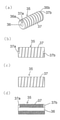
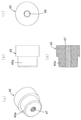
- FIG. 3 is a component diagram of a volatilization suppressing member fixed in the refill of FIG. 3, where FIG. 3A is a perspective view, FIG. 3B is a plan view, FIG. 3C is a front view, and FIG. 3D is a vertical sectional view.
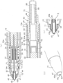
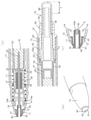
- FIG. 1 is a drawing showing a state after the start of use of the knock-type writing instrument and when it is not knocked.
- FIG. 1A is a plan view
- FIG. 1B is a front view
- FIG. 1C is a vertical sectional view in front view.
- 1 is a drawing showing a state in which the pen tip is extended after the sealing member is removed by knocking the knock-type writing tool of FIG. 1
- FIG. 1A is a partially enlarged vertical sectional view showing a divided main part
- (b). ) Is a partially enlarged perspective view of the pen tip portion
- (c) is a partially enlarged vertical sectional view of (b).
- (A) is a partially enlarged vertical cross-sectional view showing a main part in a state where the knock-type writing tool of FIG.
- b) is a partially enlarged perspective view of the pen tip portion
- (c) is a partially enlarged vertical sectional view of (b).
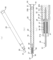
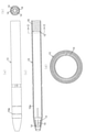
- FIG. 8 is a drawing showing an example of a refill in which a pen tip used for a knock-type writing tool is fixed.
- FIG. 8A is a perspective view
- FIG. 8B is a vertical sectional view of a front view
- FIG. It is a top view.
- FIG. 11 is a drawing showing an example of a refill in which the pen tip used for the knock-type writing tool is fixed.
- FIG. 11A is a perspective view
- FIG. 11B is a vertical sectional view of a front view
- FIG. 11C is an enlargement of a pen tip tip portion.
- the perspective view, (d) is a partially enlarged vertical sectional view of a main part.
- 11 is a drawing showing an example of a shaft tube used for a knock-type writing tool, in which (a) is a front view, (b) is a right side view, (c) is a vertical sectional view, and (d) is D of (c). -It is a D line enlarged sectional view. 11 is a drawing showing a non-knocked state of the knock-type writing instrument, where (a) is a front view, (b) is a vertical sectional view, and (c) is an enlarged X-ray sectional view of (b).
- (D) is a partially enlarged vertical sectional view of (c), (e) is an enlarged YY line sectional view of (b), and (f) is a partially enlarged vertical sectional view of (e).
- 11 is a drawing showing a knocked state of the knock-type writing tool, (a) is a front view, (b) is a vertical cross-sectional view, and (c) is a cross-sectional view showing the air flow of the sealing member portion in a cross-sectional manner.
- (D) is a cross-sectional view showing the air flow of the lid member portion in a cross-sectional manner, and (e) is a partially enlarged vertical cross-sectional view showing the main part divided.
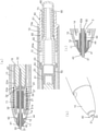
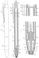
- FIG. 16 is a drawing showing the state before the start use of the knock type writing instrument which shows 4th Embodiment of this disclosure
- (a) is a front view
- (b) is a vertical sectional view of a front view
- (c) is a pen tip portion. It is a partially enlarged vertical sectional view.
- 16 is a drawing showing a state of the knock-type writing instrument at the time of writing
- (a) is a front view
- (b) is a vertical sectional view of a front view
- (c) is a partially enlarged vertical sectional view of a pen tip portion.
- .. 16 is a drawing showing an example of a refill in which a pen tip used for a knock-type writing tool is fixed.
- FIG. 16A is a perspective view
- FIG. 16A is a perspective view
- FIG. 16A is a perspective view
- FIG. 16A is a perspective view
- FIG. 16A is a perspective view
- FIG. 16A is a perspective
- 16B is a vertical sectional view of a front view
- FIG. It is a top view.
- 16 is a component diagram of the rotor of the knock mechanism, (a) is a perspective view seen from the front side, (b) is a perspective view seen from the rear side, (c) is a front view, and (d) is a vertical cross section. It is a figure.
- (A) is a vertical cross-sectional view showing a state in which the pen tip of the knock-type writing instrument of FIG. 16 is housed in the barrel (non-knock state), and (b) is a case where the internal pressure of the barrel increases in the non-knock state.
- (c) is a partial vertical cross-sectional view showing a main part on the rear end side in a knocked state.
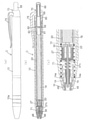
- the knock-type writing tool of the first embodiment includes a shaft cylinder 10 which is a writing tool main body, a refill 20 containing an ink storage member 18 provided in the shaft cylinder 10, and a pen. It has at least a tip 30, a seal member 40, and a knock mechanism 70.
- the pen tip 30 ejects ink from the ink storage member 18 due to a capillary phenomenon, and the knock mechanism 70 allows the pen tip 30 to freely appear and disappear from the tip of the barrel 10. It has a structure of.
- At least the sealing member 40 is provided on the outer periphery near the tip of the pen tip 30, and when the pen tip 30 is housed in the barrel 10, the central portion of the sealing member 40 is provided.
- a through hole 42 is formed in the pen tip 30 so that the pen tip 30 can slide back and forth.
- the shaft cylinder 10 serving as the main body of the writing tool is, for example, a polyacetal resin, a polyethylene resin, an acrylic resin, a polyester resin, a polyamide resin, a polyurethane resin, a polyolefin resin, a polyvinyl resin, a polycarbonate resin, or a polyether resin. It is formed of a resin, a thermoplastic resin such as a polyphenylene resin, a thermosetting resin (hereinafter, each of the above resins is simply referred to as "each resin"), and the tip portion is tapered.
- a seal member 40 is fixed to the opening 11, and a knock mechanism 70 is attached to the opening 13 on the rear end side of the other.
- a refill 20 containing an ink storage member 18 is provided in the shaft cylinder 10.
- the ink storage member 18 is impregnated with ink for writing tools such as water-based ink, oil-based ink, and heat-discolorable ink, and is, for example, natural fiber, animal hair fiber, polyacetal resin, acrylic resin, polyester resin, and polyamide.
- a fiber bundle consisting of one or a combination of two or more kinds such as a based resin, a polyurethane resin, a polyolefin resin, a polyvinyl resin, a polycarbonate resin, a polyether resin, and a polyphenylene resin, and a fiber bundle such as felt are processed. It also contains porous materials such as sponges, resin particles, and sintered bodies.
- the ink storage member 18 is configured to be housed in the refill 20.
- the composition of the ink for writing instruments to be used is not particularly limited, and suitable compounding formulations such as water-based inks, oil-based inks, and heat-discolorable inks can be used depending on the intended use of the writing instruments.
- suitable compounding formulations such as water-based inks, oil-based inks, and heat-discolorable inks can be used depending on the intended use of the writing instruments.
- an underline pen or the like can be used.
- Fluorescent dyes such as Basic Violet 11, Basic Yellow 40 and the like can be used in the ink, and heat-discolorable microcapsule pigments and the like can be contained in the ink.
- the effect of suppressing the drying of the pen tip is excellent, and the surface of the handwriting dries quickly. Even if the handwriting is rubbed, it does not stretch, and it is possible to further prevent the handwriting from being scratched even in a low temperature environment.
- the glyceryl glucoside used is ⁇ -glyceryl glucoside in which glycerin and glucose are condensed by ⁇ bond and ⁇ glyceryl glucoside condensed by ⁇ bond, and is an enzyme obtained by allowing ⁇ -glucosidase to act on a mixed solution of maltooligosaccharide and glycerin. It may be a reaction product or a product obtained by a condensation reaction of glycerin and glucose.
- Examples of the glyceryl glucoside include ⁇ -glyceryl glucoside and ⁇ -glyceryl glucoside, more preferably ⁇ -glyceryl glucoside, and specific examples of the ⁇ -glyceryl glucoside include ⁇ GG and ⁇ GG-L (all manufactured by JST Co., Ltd.).
- the amount of these glyceryl glucosides added is preferably 0.5% by mass or more and 30.0% by mass or less with respect to the total amount of the ink composition.
- These glyceryl glucosides may be used alone or in combination of two or more.
- the colorants that can be used in writing instrument inks are not particularly limited, and dyes and pigments can be used.
- a water-soluble dye can be used as the dye.
- Specific examples of the water-soluble dye include direct dyes, acid dyes, and basic dyes. These dyes may be used alone or in combination of two or more.
- pigments include carbon black such as furnest black, contact black, thermal black, and acetylene black, black iron oxide, yellow iron oxide, red iron oxide, ultramarine, dark blue, cobalt blue, titanium yellow, turquoise, and molybdate. Orange, titanium oxide, gold powder, silver powder, copper powder, aluminum powder, brass powder, tin powder, mica pigment, C.I. I.
- PIGMENT RED 2 Same 3, Same 5, Same 17, Same 22, Same 38, 41, Same 48: 2, Same 48: 3, Same 49, Same 50: 1, Same 53: 1, Same 57: 1, 58: 2, 60, 63: 1, 63: 2, 64: 1, 88, 112, 122, 123, 144, 146, 149, 166, 168, 170, 176, 177, 178, 179, 180, 185, 190, 194, 206, 207, 209, 216, 245, C.I. I. PIGMENT ORANGE 5, 10, 13, 16, 16, 36, 40, 43, C.I. I. PIGMENT VIOLET 19, 23, 31, 33, 36, 38, 50, C.I. I.
- PIGMENT BLUE 2 15: 1, 15: 2, 15: 3, 15: 4, 15: 5, 16, 17, 17, 22, 25, 60, 66, C. I. PIGMENT BROWN 25, 26, C.I. I. PIGMENT YELLOW 1, same 3, same 12, same 13, same 24, same 93, same 94, same 95, same 97, same 99, same 108, same 109, same 110, same 117, same 120, same 139, same 153, 166, 167, 173, C.I. I. PIGMENT GREEN 7, the same 10, the same 36, and the like can be mentioned.
- These pigments may be used alone or in combination of two or more. Further, a pigment and a dye can be used in combination as a colorant.
- a dispersant can also be used to stably disperse the pigment.
- the dispersant those used as dispersants for pigments, such as water-soluble resins or water-soluble resins generally used in the past, and anionic or nonionic surfactants, can be used.
- the amount of these water-soluble resins and surfactants added is preferably 0.05% by mass or more and 20.0% by mass or less with respect to 10.0% by weight of the pigment.
- These water-soluble resins and surfactants may be used alone or in combination of two or more.
- a pigment dispersion in which the pigment is dispersed in an aqueous medium can also be used.
- an inorganic pigment, an organic pigment, a fluorescent pigment and the like can be used, and they may be used alone or in combination of two or more.
- the colored resin particles are used as a colorant, those in which the resin particles are not dissolved in an organic solvent are used.
- colorless particles such as resin particles, wax particles, and resin emulsions can be used to adjust the color.
- polyethylene oxide wax particles it is possible to suppress the set-off of handwriting at the same time.
- the solid content concentration in the ink for writing tools it is preferable to set the solid content concentration in the ink for writing tools to 25% by mass or more because it is possible to suppress the set-off of handwriting.
- the polyethylene oxide wax particles when used, even if the solid content concentration in the writing instrument ink is 25% by mass or less, the set-off of the brush stroke can be suppressed, and the content of the polyethylene oxide wax particles is 0 with respect to the total amount of the ink composition. .1% by mass or more and 50.0% by mass or less is preferable, more preferably 0.5% by mass or more and 23.0% by mass or less, and most preferably 1.0% by mass or more and 15.0% by mass or less.
- the water-soluble organic solvent used for the ink for writing tools indicates an organic solvent that can dissolve 10 g or more in 100 g of water.
- these water-soluble organic solvents glycol ether and water-soluble organic solvents having a cyclic structure are preferable, and water-soluble organic solvents having a cyclic structure are more preferable, from the viewpoint of penetrability of handwriting into paper and suppression of pen tip drying. ..
- the pen tip is produced by the interaction between the glyceryl glucoside and the water-soluble organic solvent.
- the amount of these water-soluble organic solvents added is preferably 0.1% by mass or more and 50.0% by mass or less, and more preferably 5.0% by mass or more and 20.0% by mass or less with respect to the total amount of the ink composition.
- These water-soluble organic solvents may be used alone or in combination of two or more.
- the viscosity of the water-based ink for writing tools is preferably 1.0 mPa ⁇ s or more and 20.0 mPa ⁇ s or less at a measurement temperature of 25 ° C. and a shear rate of 76.6 s- 1. Further, the surface tension is preferably 30 to 60 mN / m.
- additives such as lubricants, viscosity regulators, lubricants, preservatives, fungicides, rust inhibitors, defoamers, and pH adjusters may be used in combination, if necessary. can. These additives may be used alone or in combination of two or more.
- the above-mentioned pigment and / or pigment dispersion one or more colorants selected from dyes, water and / or an organic solvent, and a dispersant are used.
- a disperser such as a homomixer
- other additives such as a viscosity modifier, a pH adjuster, a dye for adjusting the color tone, a lubricant, etc. are mixed and dissolved until they become more uniform.
- the mixed ink may be further dispersed by a disperser, or the obtained ink may be filtered or centrifuged to remove coarse particles and insoluble components. There is no problem.
- the refill 20 has a volatilization suppressing member 35 that surrounds the outer periphery of the pen tip 30 fixed to the accommodating portion 21a of the small-diameter cylindrical portion 21 on the front side thereof by fitting.
- the ink storage body 18 is housed in the accommodating portion 22a of the expanded tubular portion 22 on the rear side of the tubular portion 21 which is connected to the small-diameter tubular portion 21.
- a holding member 24 having a holding hole 23 for holding the rear side of the pen tip 30 is provided between the small-diameter cylindrical portion 21 and the expanded tubular portion 22, and these tubular portions 21, 22 and the like are provided.
- the refill containing the above can be integrally molded with a resin or the like.
- the volatilization suppressing member 35 has a cylindrical shape, has a through-type fixing hole 36 for fixing the pen tip 30 inside, and has a through-type fixing hole 36 on the outer peripheral surface.
- a spiral groove 37 is formed from one end to the other, and the ends 37a and 37b of the spiral groove are continuously provided in the cutouts 36a and 36b at each end of the fixing hole 36. ing.
- Examples of the groove shape of the spiral groove 37 include a V-shaped cross section or a U-shaped cross section, and the length of the spiral groove is a longitudinal direction (straight line) of the volatilization suppressing member 35 from the viewpoint of making it difficult for ink to volatilize. It is preferable that the length is twice or more the length of the above). Further, by setting the groove shape, width, length, etc. of the spiral groove 37 to a suitable predetermined range, it is possible to highly suppress the volatilization of ink.
- the pen tip 30 of the present embodiment has a writing portion 31 on the tip side and is formed into a rod shape.
- the central portion of the pen tip 30 is fixed to the fixing hole 36 of the volatilization suppressing member 35, and the rear end portion 32 on the rear side is inserted into the central portion on the front side in the ink storage member 18 to store ink.
- the ink stored in the member 18 is efficiently guided (supplied) to the writing portion 31 of the pen tip 30 by a capillary force (capillary phenomenon).
- the pen tip 30 is made of a porous member, and is, for example, a natural fiber, an animal hair fiber, a polyacetal resin, a polyethylene resin, an acrylic resin, a polyester resin, a polyamide resin, or a polyurethane resin.
- Parallel fiber bundles consisting of one or more combinations of polyolefin resin, polyvinyl resin, polycarbonate resin, polyether resin, polyphenylene resin, etc., fiber bundles such as felt, etc. are processed or these fiber bundles are resinified.
- a thermoplastic resin such as a polyolefin resin, an acrylic resin, a polyester resin, a polyamide resin, or a polyurethane resin, and extrusion molding. It is made of an extruded core or the like.
- Preferred pen tips 30 include a fiber bundle core, a fiber core, a sintered core, a felt core, a sponge core, an inorganic porous core, and the like, and a coated fiber core whose outer periphery is further coated with a resin film or the like. It may be.
- the porosity, size, hardness, etc. of the pen tip 30 to be used vary depending on the type of ink, the type of writing instrument, and the like. For example, the porosity is preferably 30 to 60%. Further, in the present disclosure, the "porosity" is calculated as follows. First, a writing core having a known mass and apparent volume is immersed in water, sufficiently immersed in water, and then the mass is measured in a state of being taken out of the water.
- the seal member 40 is engaged with and fixed to the tapered opening 11 at the tip of the barrel 10.
- the seal member 40 has a through hole 42 formed in the center of the main body 41 so that the pen tip 30 can slide back and forth, and is dropped off by pressing the pen tip 30 or at least in front of the tip of the pen tip 30.
- a possible sealing member 43 is integrally provided on the outer periphery of the tip of the through hole 42, and the outer periphery of the through hole 42 has elasticity for fixing to the circumferential engaging portion 12 of the opening 11.
- the combination member 44 is continuously provided.
- the sealing member 43 is integrally provided so as to close the outlet of the through hole 42, and can be easily removed by pressing the pen tip 30 by a knock operation described later or by a finger or the like.
- the connecting portion 43a has a thin skin shape. It is (ultra-thin) and has a structure that can prevent the ink from volatilizing at the pen tip 30 in the sealing member 40 including the connecting portion 43a and the sealing member 43 before falling off.
- the sealing member 43 can be easily removed from the main body 41 of the sealing member 40 by pressing the pen tip 30 or cutting the peripheral connecting portion 43a with a finger or the like.
- sealing member 40 in addition to the above resins, styrene-based elastomers, vinyl chloride-based elastomers, olefin-based elastomers, polyester-based elastomers, polyamide-based elastomers, and urethanes are used in terms of satisfying sealing properties and easiness of falling off.
- Thermoplastic elastomers such as elastomers (hereinafter, each of the above elastomers is simply referred to as "each thermoplastic elastomer"), nitrile butadiene rubber (NBR), silicone rubber, ethylene propylene rubber (EPDM), fluorosilicon rubber, fluororubber, Synthetic rubbers such as elastomer rubber, natural rubber, chloroprene rubber, butadiene rubber, and butyl rubber (hereinafter, each of the above synthetic rubbers is referred to as "each synthetic rubber”) can be preferably used, and the sealing member 40 and the shaft cylinder 10 can be used. And may be integrally formed by two-color molding (for example, two-color molding of each of the above-mentioned resins and each thermoplastic elastomer).
- the pen tip 30 can be slid back and forth in the through hole 42 of the seal member 40 by the knock operation, but the peripheral edge 42a of the rear end portion of the through hole 42 and the pen tip 30 A small gap X, specifically, a gap X of 0.02 to 1. It has a gap of 0 mm and 0.05 mm in this embodiment [see FIG. 2 (c)].
- a lid member 50 for sealing the opening is attached to the opening 20b on the rear end side of the refill 20 by fitting.
- the lid member 50 has a fitting body 51 that seals the opening 20b, and also has a cylindrical flange portion 52.
- the knock mechanism 70 of the present embodiment has an inner cylinder 60 attached to the rear end opening 13 of the shaft cylinder 10 by screwing, and front and rear inside the inner cylinder 60. It has a rotor 65 arranged so as to be movable in the direction, and a knock body 66 which is an operation unit protruding from the rear end and movable in the front-rear direction in the inner cylinder 60. Further, as shown in FIG. 2A, the inner cylinder 60 has a flange portion 61 that closely seals the L-shaped contact surface 13a of the rear end opening portion 13 of the shaft cylinder 10, and the flange portion.
- the inner cylinder portion 63 having the screw portion 62 on the outer peripheral surface on the front side of the 61, and the outer cylinder portion 64 on the rear side of the flange portion 61. Further, the tip surface 63a of the inner cylinder portion 63 is configured to be in close contact with the contact surface 53 of the flange portion 52 of the lid member 50 for sealing the opening 20b on the rear end side of the refill 20.
- the above thermoplastic elastomers and the above synthetic rubbers are used for the lid member 50 and the inner cylinder 60 in order to further improve the sealing property (sealing property) between the contact surfaces to be the end faces. It is preferable to do so.
- the knock mechanism 70 of the present embodiment allows the refill 20 to appear and disappear by a pressing operation, and is provided on the inner peripheral portion of the knock body 66, the rotor 65, and the inner cylinder 60, which are the operation portions (shown in the figure). It is equipped with a known mechanism (rotary cam mechanism) having the above.
- This knock mechanism includes holding members 14, 14 ... And holding steps 14a, 14a ... Provided at predetermined intervals in the vertical direction of the inner peripheral surface of the front portion of the barrel 10 together with the refill 20, and the outer periphery of the front side of the refill 20.
- the refill 20 is urged rearward by an elastic member 71 made of a coiled spring member held between the mounting step portion 20a and the mounting step portion 20a.
- the knock operation is performed by pressing the knock body 66 forward.
- the rotor 65 is pushed forward by the movement of the knock body 66, the rotor 65 and the front end surface of the outer cam (not shown) of the inner cylinder 60 are engaged, and the refill 20 is moved forward.
- the pen tip 30 fixed to the volatilization suppressing member 35 in the refill 20 comes out from the outlet of the through hole 42 of the sealing member 40 and becomes a writing state (see FIG. 6).
- the knock operation is performed again after writing or the like, the locked state is released, the refill 20 moves backward, and the pen tip 30 returns to the original position or the like (see FIG. 7 or the like).
- the stroke T is set to 2.0 to 15.0 mm as shown in FIG. 7 (a). By setting the above range, the knock mechanism 70 becomes efficient and volatilization can be suppressed.
- the knock-type writing tool A configured in this way is designed so that the sealing member 43 of the seal member 40 can be removed when the initial knock operation (knock operation for the first time) is performed as the knock operation. That is, as shown in FIGS. 1 and 2, the volatilization of ink by the pen tip 30 from the tip end side of the barrel 10 before the start of use is reliably suppressed by the sealing member 40 including the sealing member 43.
- the sealing member 43 can be detached when the pen tip 30 is pressed (in the writing state by knocking operation) or by tearing it off with a finger or the like, so that the sealing state can be easily released. It is possible, and by releasing this, it is possible to put it in the writing state (see FIG. 6). Even after the initial knocking operation, the tip portion of the barrel 10 is exposed only to the pen tip 30, so that the amount of ink volatilized from the pen tip 30 can be suppressed.
- the air flow between the rear portion of the barrel 10 and the outside of the writing tool is sealed at the rear portion of the barrel 10 when not in use or when not knocked.
- the rear end side of the shaft cylinder 10 When not in use (including when not knocked), the rear end side of the shaft cylinder 10 is in close contact with the flange portion 61 of the inner cylinder 60 and the contact surface 13a of the rear end opening portion 13 and is sealed. Since the front end surface 63a of the inner cylinder portion 63 and the rear end contact surface 53 of the lid member 50 are in close contact with each other and sealed, the volatilization of ink from the rear end portion of the shaft cylinder 10 is suppressed. Further, when the knock operation is performed from the unused state or the non-knock state, air is taken in from the gap X between the pen tip 30 and the seal member 40 as shown in FIG. 6 (c), and as shown in FIG. 6 (a).
- the air taken in is discharged to the outside of the writing instrument through the space (gap) between the shaft cylinder 10 and the refill 20 and the gap between the inner cylinder 63 and the rotor 65, and the internal and external pressure becomes constant, and the internal pressure inside the shaft cylinder 10 becomes constant. Ink is prevented from being ejected from the pen tip 30 due to the ascent.
- the seal member 40 as shown in the above and FIGS. 3 and 4, on the outer periphery of the volatilization suppressing member 35 surrounding the outer periphery of the pen tip 30 fixed to the accommodating portion 21a of the refill 20.
- the spiral thread groove 37 is formed, the volatilization of ink from the ink storage member 18 in the refill 20 is performed through the spiral thread groove 37, so that the ink is linear.
- the length is longer than the gaps (grooves) of the helix, and the volatilization of ink from the refill 20 alone can be suppressed.
- the sealing member 40 having the sealing member 43 and the spiral threaded groove 37 of the volatilization suppressing member 35 ensure that the ink volatilizes from the pen tip before the start of use.
- a knock-type writing tool that can be suppressed will be provided.
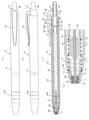
- FIGS. 8 to 10 are drawings showing other embodiments of the knock-type writing instrument of the present disclosure.
- FIGS. 8 are drawings showing a state before the start of use
- FIG. 9 is a sealing member used for the knock-type writing tool.
- the drawings and FIGS. 10 are drawings showing an example of a refill in which the pen tip used for the knock-type writing tool is fixed.
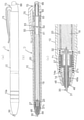
- the knock-type writing tool B of the second embodiment is sealed in place of the seal member 40 at the point where a non-slip portion 10a having a plurality of circumferential grooves formed at predetermined intervals is formed in the vicinity of the grip portion on the outer periphery of the barrel 10.
- a point that the seal member 45 having a structure having no stopping member is fixed in the opening 11 of the shaft cylinder 10 by fitting or the like, a point that the shape of the refill 20 is different, and a point that a clip portion 75 is provided outside the inner cylinder 60. It is different from the knock-type writing tool A of the first embodiment or the like in that the sealing mechanism on the rear side is slightly different.
- the knock mechanism 70 functions in the same manner as the knock-type writing tool A of the first embodiment.
- the seal member 45 has a through hole 46 formed in the central portion as shown in FIGS. 9 (a) to 9 (d), and the above-mentioned first hole 46 is formed on the inner circumference of the through hole 46.
- a spiral groove 47 similar to the spiral groove formed in the volatilization suppression member 35 of 1 embodiment is formed, and a small diameter portion 45a having a small outer diameter on the front side is fitted in the opening 11 of the barrel 10. It is configured to be fixed by a spiral or the like.
- the refill 20 of the present embodiment does not include the volatilization suppressing member 35 of the first embodiment described above, and the front side has a fixing portion 21b for fixing the pen tip 30. It differs from the refill of the first embodiment in that it has a front fixed holding portion 21c.
- the pen tip 30 ejects ink from the ink storage member 18 due to a capillary phenomenon, and the pen is ejected by the knock mechanism 70.
- the tip 30 is configured to freely appear and disappear from the tip of the barrel 10.
- a through hole 46 is formed in the center of the seal member 45 of the present embodiment so that the pen tip 30 can slide back and forth, and a spiral thread groove 47 is formed on the inner circumference of the through hole 46 of the seal member 45. Since the ink volatilizes from the sealing member 45 through the spiral spiral groove 47, the length thereof is longer than that of the linear gap (groove) or the like.
- the knock-type writing tool B of the present embodiment the knock-type writing tool that can surely suppress the volatilization of ink from the pen tip 30 is provided by the spiral screw groove 47 of the sealing member 45. Further, in the present embodiment, the sealing mechanism on the rear side of the barrel 10 is sealed by abutting the contact surface 65a of the rotor 65 and the tip surface 63a of the inner cylinder 63 when not in use or when not knocked.
- the rear part of the shaft cylinder 10 has the rear part of the shaft cylinder 10 and the outside of the writing tool when not in use or when not knocked. It is equipped with a sealing mechanism that seals the flow of air in the pen, and at the time of knocking, air flows to the outside of the writing tool to keep the internal and external pressure constant and prevent ink from ejecting from the pen tip 30 when not knocking. Volatilization of ink from the rear end of 10 is also suppressed, and when the knock operation is performed from the non-knocking state, air is taken in from the pen tip 30 and the spiral groove 47 of the sealing member 45, and the taken-in air is the shaft cylinder 10. The ink is discharged to the outside of the writing tool through the space (gap) between the refill 20 and the inner cylinder portion 63 and the rotor 65, and the internal and external pressure becomes constant. Will be prevented.
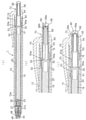
- the knock-type writing tool C of the third embodiment is provided with a mouthpiece member 25 for fixing the rear of the pen tip 30 on the tip end side of the refill 20, and the front portion of the mouthpiece member 25.
- the tip member 25 having the tip end side of the pen tip 30 fixed to the through hole 46 having the spiral groove portion 47 on the inner circumference of the seal member 45 at the point where the spiral groove 26 is formed on the outer peripheral surface slides back and forth.
- An inner wall 15 is formed on the barrel 10 to which the contact surface 53 of the lid member 50 fixed to the rear end side of the refill 20 abuts, and the inner peripheral surface on the rear side of the inner wall 15 is formed. Is different from the knock-type writing tool B of the second embodiment in that the spiral groove 16 is formed.
- FIG. 14 and 15 are explanatory views illustrating the non-knocked and knocked states of the knock-type writing instrument of the third embodiment.
- the sealing mechanism on the rear side of the barrel 10 has the contact surface 53 of the lid member 50 as the inner wall 15 of the barrel 10 when not in use or when not knocked.
- FIG. 15B the contact surface is sealed by abutting with the lid member 50, and the contact surface 53 of the lid member 50 and the inner wall 15 of the barrel 10 are opened at the time of knocking. It is something that is said.
- the pen tip 30 ejects ink from the ink storage member 18 due to a capillary phenomenon, and the pen is ejected by the knock mechanism 70.
- the tip 30 is free to appear and disappear from the tip of the barrel 10.
- a through hole 46 is formed in the center of the seal member 45 of the present embodiment so that the pen tip 30 can slide back and forth, and a spiral thread groove 47 is formed on the inner circumference of the through hole 46 of the seal member 45.
- the spiral groove 26 is also formed on the tip end side of the mouthpiece member 25, the ink volatilizes only from the exposed portion of the pen tip 30.
- the volatilization of ink can be suppressed. Further, by setting the groove shape, width, length, etc. of the spiral groove 47 and the spiral groove 26 of the mouth member 25 within a suitable predetermined range, the volatilization of ink is suppressed and the internal and external pressure due to the flow of air is suppressed. It will be possible to achieve a high degree of compatibility with keeping it constant. Therefore, in the knock-type writing tool C of the present embodiment, the volatilization of ink from the pen tip 30 can be reliably suppressed by the spiral groove 47 of the seal member 45 and the spiral groove 26 of the mouth member 25. A knock-type writing tool will be provided.
- the sealing mechanism on the rear side of the barrel 10 is sealed by the contact surface 53 of the lid member 50 coming into contact with the inner wall 15 of the barrel 10 when not in use or when not knocked. Since this contact surface is opened at the time of knocking, the shaft cylinder 10 is attached to the rear portion of the shaft cylinder 10 when not in use or when not knocked, as in the first and second embodiments.
- the volatilization of ink from the rear end of the barrel 10 is also suppressed, and when the knock operation is performed from the non-knocking state, as shown in FIGS. 11 to 14 and 15 (b) to 15 (e).
- Air is taken in from the spiral groove 47 of the pen tip 30 and the seal member 45, and the spiral groove 26 of the mouth member 25, and the taken in air is the space (gap) between the shaft cylinder 10 and the refill 20, the shaft cylinder 10 and the like.
- the ink is discharged to the outside of the writing instrument through the gap with the rotor 65, and the internal and external pressure becomes constant, so that ink is prevented from being ejected from the pen tip 30 due to the increase in the internal pressure inside the barrel 10.
- the knock-type writing tool D of the fourth embodiment has a configuration in which the pen tip 30 of the refill 20 is separated from the ink storage member 18 by an infestation operation, and the refill 20 is infested at the rear portion of the barrel 10 by a pressing operation.
- the knock mechanism is composed of a cam mechanism consisting of a knock body as an operation unit and a rotor, and the rotor is provided with a valve member that opens by the internal pressure of the inner surface of the barrel. 2 It is different from the writing tool B and the like of the embodiment.
- the knock-type writing tool D of the fourth embodiment has a small-diameter tubular portion 21 of the refill 20 so that the pen tip 30 of the refill 20 is separated from the ink storage member 18 by the infestation operation.
- a tip fixing member 27 for fixing the pen tip 30 having a cushion member is attached.
- the tip fixing member 27 has a main body portion 27a fixed to the small-diameter tubular portion 21 of the refill 20 by fitting or the like, and a pen tip 30 fixed to the tip. It has a fixing portion 27b to be attached, and also has a cushion member 27c integrally composed of a spring portion between the main body portion 27a and the fixing portion 27b.
- the seal member 48 has a through hole 49 in the central portion, and is fixed to the inside of the opening 11 of the shaft cylinder 10 by fitting or the like.
- the knock mechanism 70 that allows the refill 20 provided at the rear portion of the axle cylinder 10 of this embodiment to appear and disappear by a pressing operation is composed of a cam mechanism including a knock body 66 as an operation unit and a rotor 65, and is composed of a rotor 65. Is equipped with a valve member 68 that opens by the internal pressure of the inner surface of the barrel 10.
- the rotor 65 is arranged in front of the small diameter portion 65a which is inserted into the knock body 66 which is the operation portion and is used for centering, and the small diameter portion 65a.
- the large diameter portion 65b is composed of a large diameter portion 65b, the large diameter portion 65b has a larger diameter than the small diameter portion 65a, and the large diameter portion 65b and the small diameter portion 65a have a cylindrical shape.
- Cam portions 65c, 65c, etc. having a shape complementary to the cam portion (not shown) of the knock body 66, which is an operation portion, are formed on the rear end surface of the large diameter portion 65b to form a cam mechanism.
- the front end surface has a concave flange portion 65d that comes into contact with the lid member 50.
- a valve member 68 is attached to the outer peripheral surface and the end surface of the small diameter portion 65a of the rotor 65 so as to close the opening.
- the valve member 68 has a wristwatch-shaped valve portion 68a, a ring-shaped portion 68b separated from the valve portion 68a, and the valve portion 68a and the ring-shaped portion 68b in the front-rear direction.
- An elastic body integrally formed with a continuous portion 68c connected to is attached.
- valve portion 68 In the state where the valve portion 68 is attached to the rotor 65, the rear end opening of the small diameter portion 65a is closed by the valve portion 68a, the ring-shaped portion 68b is fitted in the peripheral groove of the small diameter portion 65a, and the continuous portion is in the vertical groove. 68c is fitted and is in close contact.
- the valve member 68 can be molded using, for example, the above-mentioned synthetic rubbers, thermoplastic elastomers, and the like, and the rotor 65 including the valve member 68 can be integrally molded by two-color molding.
- the rotor 65 is made of polyacetal
- the valve member 68 is a styrene-based elastomer, and is molded by two-color molding.
- the knock mechanism in this embodiment is performed by pressing the knock body 66, which is an operation unit, forward, and moving the rotor 65 forward together with the knock body 66 to a predetermined position in the inner cylinder 60.
- FIG. 16 shows a state before the start of use of the knock-type writing tool of the fourth embodiment, and the tip of the tip fixing member 27 to which the pen tip 30 attached to the tip side of the refill 20 is fixed is the through hole 49 of the seal member 48.
- the rear end side of the pen tip 30 is separated (separated) from the ink storage member 18, no ink is supplied, and the ink does not volatilize from the pen tip 30.
- the rotor 65 moves forward to a predetermined position as shown in FIGS. 17 and 18.
- the tip fixing member 27 moves forward, but the step portion 27b1 of the fixing portion 27b abuts on the outer peripheral surface 48a on the rear end side of the sealing member 48 to prevent the movement, and the cushion composed of the spring portion.
- the member 27c is reduced in diameter (shrinkage) due to its elastic force, the rear end portion 32 of the pen tip 30 is inserted into the ink storage member 18, and the pen tip 30 exits from the outlet of the through hole 49 of the seal member 48.
- the ink of the ink storage member 18 is supplied to the writing unit 31 of the pen tip 30 by the capillary force to be in the writing state.
- a knock operation pressing the knock body 66
- the cam mechanism is released from the lock by the cam mechanism such as the rotor 65, the rotor 65 is rotated, and then the operation unit is contacted.
- the applied force is released, the rotor 65 moves further backward due to the urging force of the elastic member 71, and as shown in FIG. 16, the knock-type writing tool D is in the non-writing state again.
- the rear end side 32 of the pen tip 30 is inserted into the ink storage member 18 at the time of writing, and the ink is supplied to the writing unit 31 of the pen tip 30. Since the rear end portion of the pen tip 30 has a structure separated (separated) from the ink supply member 18, the volatilization of ink from the ink storage member 18 is surely suppressed in combination with the seal member 48. Further, even when the internal pressure in the barrel 10 increases, the rear end portion of the pen tip 30 is separated (separated) from the ink supply member 18, so that ink does not spurt out.
- FIG. 20 (a) is a vertical cross-sectional view showing a state in which the pen tip of the knock-type writing instrument of FIG. 16 is housed in the barrel (non-knock state), and FIG. 20 (b) shows an increase in the internal pressure of the barrel in the non-knock state.
- a partial vertical cross-sectional view showing a main part on the rear end side in the knocked state is a partial vertical cross-sectional view showing the main part on the rear end side in the knocked state.
- the refill 20 moves forward, so that the contact surface 65a of the rotor 65 and the tip of the inner cylinder portion 63 are as shown in FIG. 20 (c). Since the surface 63a is opened, air outside the writing tool enters through the gap between the knock body 66 and the inner cylinder 60 and is taken into the shaft cylinder 10, so that the internal and external pressure becomes constant.
- the knock-type writing instrument D of the present embodiment is provided with a mechanism for taking in air on the rear end side of the barrel 10 and purging when the internal pressure of the barrel 10 increases, and the simple structure makes it more efficient. It can be carried out.
- the knock-type writing instrument of the present disclosure is not limited to each of the above-described embodiments, and various modifications can be made without changing the technical idea of the present disclosure.
- the structure in which the valve member 68 is attached to the rotor 65 in the knock-type writing tool D of the above embodiment is applied to each of the rotors 65 of the writing tools A to C of the first to third embodiments, and the internal pressure in the shaft cylinder 10 is increased. If it rises, air may be purged from the rear end side.
- the pen tip 30 may be a rod-shaped pen tip, which may be in the shape of a cannonball.
- the inks for writing tools water-based inks, oil-based inks, heat-discoloring inks
- liquid cosmetics, liquid chemicals, coating liquids, correction fluids, and the like may be used. be.
- Example 1 A knock-type writing tool having a pen tip according to the following configuration and FIGS. 1 to 7 and an ink for writing tools having the following composition were used. For the dimensions of the pen tip and writing instrument, the sizes shown below were used.
- Shaft cylinder 10 Made of polypropylene, length 127 mm, central inner diameter 9 mm; outer diameter 11 mm
- Ink storage member PET fiber bundle, porosity 85%, ⁇ 6 x 80 mm
- Refill 20 Made of polypropylene, length 97 mm, central inner diameter 6 mm
- Pen tip 30 Made of polyacetal, ⁇ 1.0 x 30 mm
- Volatilization suppression member 35 Made of polyacetal, spiral groove: U-shaped groove, width 0.3 mm, number of spirals: 8 (circumference)
- Seal member 40 Made of thermoplastic elastomer, the shaft cylinder 10 and the seal member 40 are molded in two colors Gap X: 0.05 mm, Stroke T: 6 mm
- the lid member 50, inner cylinder 60, rotor 65, and knock body 66 are all made of polypropylene.
- Elastic member 71 made of stainless steel.
- the pen tip 30 seals the sealing member 40. It broke through the member 43 and came out.
- the sealing member 43 was continuously installed in a state where it could be removed from the sealing member 40, but it was confirmed that the sealing member 43 could be easily removed by picking it with a finger. It was confirmed that the sealing member 43 of the sealing member 40 can be easily removed when the pen tip 30 is pressed (in a writing state by knocking operation) and / or by tearing it off with a finger or the like. It was possible to put it in the writing state by separating it (see FIG. 6). Further, it was confirmed by sensory evaluation that there was no volatilization of ink from the rear end portion of the shaft cylinder 10 due to the sealing mechanism provided on the rear end side of the shaft cylinder 10.
- a knock-type writing tool capable of reliably suppressing the volatilization of ink from the pen tip before the start of use can be obtained.
Landscapes
- Mechanical Pencils And Projecting And Retracting Systems Therefor, And Multi-System Writing Instruments (AREA)
- Pens And Brushes (AREA)
Abstract
La présente invention concerne un instrument d'écriture de type à percussion dans lequel il est possible de supprimer, avec certitude, la volatilisation de l'encre à partir d'une pointe de stylo, au moins jusqu'au commencement de l'utilisation. La présente invention concerne un instrument d'écriture de type à percussion (A) dans lequel une recharge (20) est logée à l'intérieur d'un cylindre d'arbre (10), et une pointe de stylo (30) délivre, par capillarité, une encre provenant d'un élément de stockage d'encre (18) logé dans la recharge (20), en plus de ladite pointe de stylo (30) qui est librement rétractable à partir d'une extrémité de pointe du cylindre d'arbre (10) au moyen d'un mécanisme de percussion (70) qui constitue le cylindre d'arbre (10), ledit instrument d'écriture de type à percussion (A) étant caractérisé en ce qu'il comprend au moins un élément d'étanchéité (40) au niveau d'une périphérie externe de celui-ci à proximité d'un côté de partie d'extrémité de pointe de la pointe de stylo (30), ledit élément d'étanchéité (40) ayant une partie centrale dans laquelle est formé un trou traversant (42) par lequel la pointe de stylo (30) peut coulisser vers l'avant et vers l'arrière lorsque la pointe de stylo (30) est logée à l'intérieur du cylindre d'arbre (10).
Priority Applications (3)
| Application Number | Priority Date | Filing Date | Title |
|---|---|---|---|
| US18/005,908 US12162305B2 (en) | 2020-07-20 | 2021-07-15 | Knock-type writing instrument |
| CN202180063754.XA CN116323238B (zh) | 2020-07-20 | 2021-07-15 | 揿动式书写工具 |
| EP21845975.8A EP4183593A4 (fr) | 2020-07-20 | 2021-07-15 | Instrument d'écriture de type à percussion |
Applications Claiming Priority (2)
| Application Number | Priority Date | Filing Date | Title |
|---|---|---|---|
| JP2020-123622 | 2020-07-20 | ||
| JP2020123622A JP7508299B2 (ja) | 2020-07-20 | 2020-07-20 | ノック式筆記具 |
Publications (1)
| Publication Number | Publication Date |
|---|---|
| WO2022019208A1 true WO2022019208A1 (fr) | 2022-01-27 |
Family
ID=79729515
Family Applications (1)
| Application Number | Title | Priority Date | Filing Date |
|---|---|---|---|
| PCT/JP2021/026625 Ceased WO2022019208A1 (fr) | 2020-07-20 | 2021-07-15 | Instrument d'écriture de type à percussion |
Country Status (5)
| Country | Link |
|---|---|
| US (1) | US12162305B2 (fr) |
| EP (1) | EP4183593A4 (fr) |
| JP (2) | JP7508299B2 (fr) |
| CN (1) | CN116323238B (fr) |
| WO (1) | WO2022019208A1 (fr) |
Citations (9)
| Publication number | Priority date | Publication date | Assignee | Title |
|---|---|---|---|---|
| JPS49107421U (fr) * | 1973-01-08 | 1974-09-13 | ||
| JPS5872089U (ja) * | 1981-11-11 | 1983-05-16 | アンコス株式会社 | 筆記具 |
| JPS6034486U (ja) * | 1983-08-17 | 1985-03-09 | 東洋ポリマ−株式会社 | ノツク式キヤツプレス筆記具 |
| JPH01281999A (ja) | 1988-05-07 | 1989-11-13 | Ankosu Kk | 乾燥防止機構を有するキャップレス筆記具のリフィール機構 |
| JPH0261687U (fr) * | 1988-10-28 | 1990-05-08 | ||
| JPH0464971A (ja) | 1990-07-03 | 1992-02-28 | Mitsubishi Electric Corp | 磁気記録再生装置 |
| JP2003191683A (ja) | 2001-12-26 | 2003-07-09 | Pentel Corp | 出没式筆記具 |
| US20070134047A1 (en) * | 2005-12-14 | 2007-06-14 | Hu Cho-Kai | Sealing device for writing tip |
| JP2010517815A (ja) * | 2007-02-01 | 2010-05-27 | サンフォード エル.ピー. | 引込み自在型用具用のシールアセンブリ |
Family Cites Families (18)
| Publication number | Priority date | Publication date | Assignee | Title |
|---|---|---|---|---|
| US3039436A (en) * | 1956-09-19 | 1962-06-19 | Exner Hellmuth Alfred Artur | Fountain pen with retractable writing element |
| US4469462A (en) | 1981-11-11 | 1984-09-04 | Ancos Co., Ltd. | Writing instrument with sealing tip |
| KR830002943Y1 (ko) | 1982-05-13 | 1983-12-23 | 김유승 | 필기구 |
| US4618280A (en) * | 1984-02-01 | 1986-10-21 | Toyo Polymer Co., Ltd. | Push-button writing instrument with front seal means |
| US4911570A (en) * | 1987-07-27 | 1990-03-27 | Rhoades Clark J | Enclosure means for liquid applicators |
| KR910004175Y1 (ko) | 1989-01-23 | 1991-06-17 | 가부시키가이샤 고도부키 | 캡없는 필기구 |
| JP4666794B2 (ja) * | 2001-03-13 | 2011-04-06 | 三菱鉛筆株式会社 | キャップレス筆記具 |
| JP2005516830A (ja) | 2002-02-13 | 2005-06-09 | イノデスク・インコーポレイテッド | 前方室を備えたキャップなしの引込可能な密封された筆記具 |
| WO2005044586A2 (fr) * | 2003-10-20 | 2005-05-19 | Avery Dennison Corporation | Instruments d'ecriture retractables a encres volatiles |
| JP2006255943A (ja) * | 2005-03-15 | 2006-09-28 | Mitsubishi Pencil Co Ltd | 加圧式の筆記具 |
| CN101092093A (zh) | 2006-06-23 | 2007-12-26 | 太幸精密工业股份有限公司 | 墨水笔改良结构 |
| US20080008517A1 (en) * | 2006-07-05 | 2008-01-10 | Ta Shin Precision Ind. Co., Ltd. | Ink-Pen |
| WO2010100800A1 (fr) | 2009-03-01 | 2010-09-10 | Tsukada Fujio | Instrument d'écriture |
| CN104640712B (zh) * | 2012-06-07 | 2016-09-28 | 三菱铅笔株式会社 | 圆珠笔 |
| CN108146102A (zh) * | 2017-12-30 | 2018-06-12 | 贝发集团股份有限公司 | 笔芯及其使用了其的书写工具 |
| DE202018002072U1 (de) | 2018-04-24 | 2019-07-25 | Schwan-Stabilo Cosmetics Gmbh & Co. Kg | Gerät zum Auftragen einer viskosen Substanz |
| JP7474059B2 (ja) * | 2020-02-06 | 2024-04-24 | 三菱鉛筆株式会社 | マーキングペン |
| EP3915800A1 (fr) * | 2020-05-29 | 2021-12-01 | Société BIC | Joint autoréparable pour un instrument d'écriture |
-
2020
- 2020-07-20 JP JP2020123622A patent/JP7508299B2/ja active Active
-
2021
- 2021-07-15 CN CN202180063754.XA patent/CN116323238B/zh active Active
- 2021-07-15 EP EP21845975.8A patent/EP4183593A4/fr active Pending
- 2021-07-15 WO PCT/JP2021/026625 patent/WO2022019208A1/fr not_active Ceased
- 2021-07-15 US US18/005,908 patent/US12162305B2/en active Active
-
2024
- 2024-06-19 JP JP2024098615A patent/JP7770473B2/ja active Active
Patent Citations (9)
| Publication number | Priority date | Publication date | Assignee | Title |
|---|---|---|---|---|
| JPS49107421U (fr) * | 1973-01-08 | 1974-09-13 | ||
| JPS5872089U (ja) * | 1981-11-11 | 1983-05-16 | アンコス株式会社 | 筆記具 |
| JPS6034486U (ja) * | 1983-08-17 | 1985-03-09 | 東洋ポリマ−株式会社 | ノツク式キヤツプレス筆記具 |
| JPH01281999A (ja) | 1988-05-07 | 1989-11-13 | Ankosu Kk | 乾燥防止機構を有するキャップレス筆記具のリフィール機構 |
| JPH0261687U (fr) * | 1988-10-28 | 1990-05-08 | ||
| JPH0464971A (ja) | 1990-07-03 | 1992-02-28 | Mitsubishi Electric Corp | 磁気記録再生装置 |
| JP2003191683A (ja) | 2001-12-26 | 2003-07-09 | Pentel Corp | 出没式筆記具 |
| US20070134047A1 (en) * | 2005-12-14 | 2007-06-14 | Hu Cho-Kai | Sealing device for writing tip |
| JP2010517815A (ja) * | 2007-02-01 | 2010-05-27 | サンフォード エル.ピー. | 引込み自在型用具用のシールアセンブリ |
Non-Patent Citations (1)
| Title |
|---|
| See also references of EP4183593A4 |
Also Published As
| Publication number | Publication date |
|---|---|
| EP4183593A4 (fr) | 2024-08-14 |
| CN116323238B (zh) | 2024-11-19 |
| JP7770473B2 (ja) | 2025-11-14 |
| CN116323238A (zh) | 2023-06-23 |
| US12162305B2 (en) | 2024-12-10 |
| EP4183593A1 (fr) | 2023-05-24 |
| JP2022020234A (ja) | 2022-02-01 |
| JP2024111151A (ja) | 2024-08-16 |
| JP7508299B2 (ja) | 2024-07-01 |
| US20230347683A1 (en) | 2023-11-02 |
Similar Documents
| Publication | Publication Date | Title |
|---|---|---|
| JP2022107806A (ja) | 熱変色性筆記具 | |
| US9636940B2 (en) | Writing instrument | |
| CN104640712A (zh) | 圆珠笔 | |
| WO2022019208A1 (fr) | Instrument d'écriture de type à percussion | |
| JP6423240B2 (ja) | 筆記具 | |
| RU2350475C2 (ru) | Комбинированный пишущий инструмент | |
| JP7316086B2 (ja) | 出没式筆記具およびマーカーリフィル | |
| JP7676459B2 (ja) | ノック式ボールペン | |
| CN113597375B (zh) | 用于书写工具的可伸缩元件 | |
| JP6126829B2 (ja) | 筆記具 | |
| JP7503456B2 (ja) | 筆記具 | |
| JP6126828B2 (ja) | 筆記具 | |
| JP3698807B2 (ja) | ボールペンのリフィール | |
| JP4919756B2 (ja) | 筆記具 | |
| JP3763425B2 (ja) | 複式筆記具 | |
| JP3643186B2 (ja) | ボールペンのリフィール | |
| JP3643182B2 (ja) | 複式筆記具 | |
| JP2023105497A (ja) | キャップ式筆記具 | |
| JP3765532B2 (ja) | 複式筆記具 | |
| JP3791811B2 (ja) | ボールペン | |
| JPH09188093A (ja) | 複式筆記具 | |
| JP2015229254A (ja) | 筆記具 | |
| JP2000247090A (ja) | 塗布具 | |
| JP2004338237A (ja) | ボールペン | |
| JPH09188092A (ja) | 複式筆記具 |
Legal Events
| Date | Code | Title | Description |
|---|---|---|---|
| 121 | Ep: the epo has been informed by wipo that ep was designated in this application |
Ref document number: 21845975 Country of ref document: EP Kind code of ref document: A1 |
|
| NENP | Non-entry into the national phase |
Ref country code: DE |
|
| ENP | Entry into the national phase |
Ref document number: 2021845975 Country of ref document: EP Effective date: 20230220 |