WO2022019246A1 - 過冷却解除装置、蓄熱装置及び動力装置 - Google Patents
過冷却解除装置、蓄熱装置及び動力装置 Download PDFInfo
- Publication number
- WO2022019246A1 WO2022019246A1 PCT/JP2021/026888 JP2021026888W WO2022019246A1 WO 2022019246 A1 WO2022019246 A1 WO 2022019246A1 JP 2021026888 W JP2021026888 W JP 2021026888W WO 2022019246 A1 WO2022019246 A1 WO 2022019246A1
- Authority
- WO
- WIPO (PCT)
- Prior art keywords
- release device
- heat storage
- supercooling release
- load
- storage material
- Prior art date
- Legal status (The legal status is an assumption and is not a legal conclusion. Google has not performed a legal analysis and makes no representation as to the accuracy of the status listed.)
- Ceased
Links
Images



Classifications
-
- F—MECHANICAL ENGINEERING; LIGHTING; HEATING; WEAPONS; BLASTING
- F28—HEAT EXCHANGE IN GENERAL
- F28D—HEAT-EXCHANGE APPARATUS, NOT PROVIDED FOR IN ANOTHER SUBCLASS, IN WHICH THE HEAT-EXCHANGE MEDIA DO NOT COME INTO DIRECT CONTACT
- F28D20/00—Heat storage plants or apparatus in general; Regenerative heat-exchange apparatus not covered by groups F28D17/00 or F28D19/00
- F28D20/02—Heat storage plants or apparatus in general; Regenerative heat-exchange apparatus not covered by groups F28D17/00 or F28D19/00 using latent heat
- F28D20/028—Control arrangements therefor
-
- F—MECHANICAL ENGINEERING; LIGHTING; HEATING; WEAPONS; BLASTING
- F01—MACHINES OR ENGINES IN GENERAL; ENGINE PLANTS IN GENERAL; STEAM ENGINES
- F01P—COOLING OF MACHINES OR ENGINES IN GENERAL; COOLING OF INTERNAL-COMBUSTION ENGINES
- F01P7/00—Controlling of coolant flow
- F01P7/14—Controlling of coolant flow the coolant being liquid
- F01P7/16—Controlling of coolant flow the coolant being liquid by thermostatic control
-
- F—MECHANICAL ENGINEERING; LIGHTING; HEATING; WEAPONS; BLASTING
- F01—MACHINES OR ENGINES IN GENERAL; ENGINE PLANTS IN GENERAL; STEAM ENGINES
- F01M—LUBRICATING OF MACHINES OR ENGINES IN GENERAL; LUBRICATING INTERNAL COMBUSTION ENGINES; CRANKCASE VENTILATING
- F01M5/00—Heating, cooling, or controlling temperature of lubricant; Lubrication means facilitating engine starting
- F01M5/002—Cooling
-
- F—MECHANICAL ENGINEERING; LIGHTING; HEATING; WEAPONS; BLASTING
- F01—MACHINES OR ENGINES IN GENERAL; ENGINE PLANTS IN GENERAL; STEAM ENGINES
- F01M—LUBRICATING OF MACHINES OR ENGINES IN GENERAL; LUBRICATING INTERNAL COMBUSTION ENGINES; CRANKCASE VENTILATING
- F01M5/00—Heating, cooling, or controlling temperature of lubricant; Lubrication means facilitating engine starting
- F01M5/02—Conditioning lubricant for aiding engine starting, e.g. heating
- F01M5/021—Conditioning lubricant for aiding engine starting, e.g. heating by heating
-
- F—MECHANICAL ENGINEERING; LIGHTING; HEATING; WEAPONS; BLASTING
- F01—MACHINES OR ENGINES IN GENERAL; ENGINE PLANTS IN GENERAL; STEAM ENGINES
- F01P—COOLING OF MACHINES OR ENGINES IN GENERAL; COOLING OF INTERNAL-COMBUSTION ENGINES
- F01P11/00—Component parts, details, or accessories not provided for in, or of interest apart from, groups F01P1/00 - F01P9/00
- F01P11/14—Indicating devices; Other safety devices
- F01P11/20—Indicating devices; Other safety devices concerning atmospheric freezing conditions, e.g. automatically draining or heating during frosty weather
-
- F—MECHANICAL ENGINEERING; LIGHTING; HEATING; WEAPONS; BLASTING
- F01—MACHINES OR ENGINES IN GENERAL; ENGINE PLANTS IN GENERAL; STEAM ENGINES
- F01P—COOLING OF MACHINES OR ENGINES IN GENERAL; COOLING OF INTERNAL-COMBUSTION ENGINES
- F01P3/00—Liquid cooling
- F01P3/20—Cooling circuits not specific to a single part of engine or machine
-
- F—MECHANICAL ENGINEERING; LIGHTING; HEATING; WEAPONS; BLASTING
- F28—HEAT EXCHANGE IN GENERAL
- F28D—HEAT-EXCHANGE APPARATUS, NOT PROVIDED FOR IN ANOTHER SUBCLASS, IN WHICH THE HEAT-EXCHANGE MEDIA DO NOT COME INTO DIRECT CONTACT
- F28D20/00—Heat storage plants or apparatus in general; Regenerative heat-exchange apparatus not covered by groups F28D17/00 or F28D19/00
- F28D20/02—Heat storage plants or apparatus in general; Regenerative heat-exchange apparatus not covered by groups F28D17/00 or F28D19/00 using latent heat
-
- F—MECHANICAL ENGINEERING; LIGHTING; HEATING; WEAPONS; BLASTING
- F01—MACHINES OR ENGINES IN GENERAL; ENGINE PLANTS IN GENERAL; STEAM ENGINES
- F01P—COOLING OF MACHINES OR ENGINES IN GENERAL; COOLING OF INTERNAL-COMBUSTION ENGINES
- F01P11/00—Component parts, details, or accessories not provided for in, or of interest apart from, groups F01P1/00 - F01P9/00
- F01P11/14—Indicating devices; Other safety devices
- F01P2011/205—Indicating devices; Other safety devices using heat-accumulators
-
- Y—GENERAL TAGGING OF NEW TECHNOLOGICAL DEVELOPMENTS; GENERAL TAGGING OF CROSS-SECTIONAL TECHNOLOGIES SPANNING OVER SEVERAL SECTIONS OF THE IPC; TECHNICAL SUBJECTS COVERED BY FORMER USPC CROSS-REFERENCE ART COLLECTIONS [XRACs] AND DIGESTS
- Y02—TECHNOLOGIES OR APPLICATIONS FOR MITIGATION OR ADAPTATION AGAINST CLIMATE CHANGE
- Y02E—REDUCTION OF GREENHOUSE GAS [GHG] EMISSIONS, RELATED TO ENERGY GENERATION, TRANSMISSION OR DISTRIBUTION
- Y02E60/00—Enabling technologies; Technologies with a potential or indirect contribution to GHG emissions mitigation
- Y02E60/14—Thermal energy storage
Definitions
- This disclosure relates to a supercooling release device, a heat storage device, and a power device.
- a heat storage device that stores heat and dissipates heat by performing a phase transition between a liquid phase and a solid phase of a heat storage material.
- the heat storage device includes a supercooling release device that releases the supercooled state of the supercooled heat storage material.
- the heat storage device provided with the supercooling release device is used for, for example, a power device including a power engine such as a gasoline engine or an electric motor.
- Patent Documents 1 to 3 disclose a conventional supercooling release device that releases a supercooled state of a heat storage material by utilizing bending deformation of a flexible member. Specifically, in the supercooling release device of Patent Document 1, the supercooling state of the heat storage material is released by the sliding friction force generated by pressing the coil-shaped trigger spring from the outside to bend and deform it. In the supercooling release device of Patent Documents 2 and 3, a flexible plate-shaped member is pressed from the outside to be bent and deformed. Along with this deformation, the crystals of the heat storage material come into contact with the surrounding heat storage material in the supercooled state, and the supercooled state of the heat storage material is released.
- the member for releasing the supercooled state is in a state of being able to bend and deform even when an unintended force is applied from the outside in the supercooled state. Therefore, depending on the usage environment, the supercooled state may be released at an unintended timing due to unavoidable vibration, sudden collision of an object, or the like.
- the present disclosure provides a new supercooling release device suitable for releasing the supercooled state at an intended timing.
- the supercooling release device is A supercooling release device that releases the supercooled state of the heat storage material.
- the supercooling release device includes a first member and a second member that can come into contact with each other.
- Each of the first member and the second member contains a metal and contains metal.
- the supercooling is carried out in a state where a load is continuously applied to at least one of the first member and the second member so as to bring at least a part of the surface of the first member and at least a part of the surface of the second member into contact with each other. The state is maintained, The load is reduced when the supercooled state should be released.
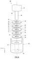
- FIG. 1 is a schematic cross-sectional view of the supercooling release device according to the first embodiment of the present disclosure.
- FIG. 2 is an exploded perspective view showing a part of the supercooling release device shown in FIG.
- FIG. 3 is an exploded view of the supercooling release device shown in FIG.
- FIG. 4 is a schematic cross-sectional view of the supercooling release device according to the second embodiment of the present disclosure.
- FIG. 5 is an exploded perspective view showing a part of the supercooling release device shown in FIG.
- FIG. 6A is a perspective view showing a modified example of the third member included in the supercooling release device shown in FIG.
- FIG. 6B is a perspective view showing another modification of the third member.
- FIG. 6C is a perspective view showing still another modification of the third member.
- FIG. 6A is a perspective view showing a modified example of the third member included in the supercooling release device shown in FIG.
- FIG. 6B is a perspective view showing another modification of the third member
- FIG. 7 is an exploded perspective view showing a part of the supercooling release device according to the third embodiment of the present disclosure.
- FIG. 8 is an exploded perspective view showing a part of the supercooling release device according to the fourth embodiment of the present disclosure.
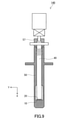
- FIG. 9 is a schematic cross-sectional view of the supercooling release device according to the fifth embodiment of the present disclosure.
- FIG. 10 is an exploded perspective view showing a part of the supercooling release device shown in FIG.
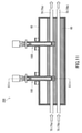
- FIG. 11 is a schematic cross-sectional view of a heat storage device using the supercooling release device of the present disclosure.
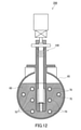
- FIG. 12 is a schematic cross-sectional view taken along the line XII-XII of the heat storage device shown in FIG.
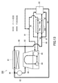
- FIG. 13 is a schematic configuration diagram of a power unit using the heat storage device of the present disclosure.
- a supercooling release device capable of stably obtaining a supercooling release function can be realized by using an overcooling release device that maintains the supercooled state and reduces the load when the supercooled state should be released. ..
- the supercooling release device is A supercooling release device that releases the supercooled state of the heat storage material.
- the supercooling release device includes a first member and a second member that can come into contact with each other.
- Each of the first member and the second member contains a metal and contains metal.
- the supercooling is carried out while a load is continuously applied to at least one of the first member and the second member so as to bring at least a part of the surface of the first member and at least a part of the surface of the second member into contact with each other.
- the state is maintained, The load is reduced when the supercooled state should be released.
- the supercooled state of the heat storage material can be released by the following method.
- the supercooling release device is brought into contact with the supercooled heat storage material in a state where no external load is applied to the first member and the second member.
- the stimulus causes the crystallization of the heat storage material to proceed.
- the crystals of the heat storage material are arranged between the first member and the second member.
- a load is applied to at least one of the first member and the second member to bring the first member and the second member into close contact with each other.
- the heat storage material is heated in this state, the heat storage material existing around the supercooling release device melts.
- the trace amount of heat storage material existing between the first member and the second member maintains a crystalline state.
- the heat storage material existing around the supercooling release device changes to the supercooled state.
- the supercooled heat storage material penetrates between the first member and the second member and comes into contact with the crystals of the heat storage material.
- the supercooled state of the heat storage material is released, and the heat storage material solidifies.
- the supercooling release device maintains the supercooling state and releases the supercooling state in a state where the load for bringing these members into contact with each other is continuously applied to at least one of the first member and the second member. Reduce the load when it should.
- Such a supercooling release device is suitable for releasing the supercooled state at an intended timing.
- each of the first member and the second member may have a plate-like shape.
- the supercooling release device is suitable for releasing the supercooled state at an intended timing.
- the first member and the second member each have a flat surface as a surface that comes into contact with each other under the load. Further, it may have at least one selected from the group consisting of non-flat surfaces that are elastically deformed so that the contact area is expanded by applying the load.
- the supercooling release device is suitable for releasing the supercooled state at an intended timing.
- the supercooling release device is the first member and the second member in a direction orthogonal to the direction in which the load is applied. Further, a guide member for regulating the displacement may be provided. According to the fourth aspect, the supercooling release device can easily maintain the supercooling release function even after repeated use.
- the guide member may include at least one selected from the group consisting of a cylinder and a shaft, and the cylinder is the cylinder.
- the first member and the second member may be accommodated, and the shaft may be inserted into a through hole formed in each of the first member and the second member.
- the supercooling release device can easily maintain the supercooling release function even after repeated use.
- the supercooling release device may further include a third member, the first member and the third member.
- the second member may be located between the two members, or the first member may be located between the second member and the third member, and the third member may have a flat surface.
- And may have at least one selected from the group consisting of non-flat surfaces that elastically deform to increase flatness upon application of the load.
- the supercooling release device may further include a third member, the first member and the third member.
- the second member may be located between the two members, or the first member may be located between the second member and the third member, and the third member may be a resin member. It may be.
- the third member is easily elastically deformed by being compressed in contact with, for example, the first member or the second member. The elastically deformed third member can uniformly apply a load to the first member or the second member. As a result, the second member and the first member can be easily brought into close contact with each other.
- the supercooling release device can release the supercooled state of the heat storage material with high probability.
- the supercooling release device may further include a fourth member, and the first member is between the third member and the fourth member.
- One member and the second member may be located, and the fourth member is selected from a group consisting of a flat surface and a non-flat surface elastically deformed so as to increase flatness by applying the load. You may have at least one.
- the supercooling release device can release the supercooled state of the heat storage material with a higher probability.
- the first member and the second member each have the load applied to each other.
- the surface to be contacted may have a flat surface.
- the supercooling release device is suitable for releasing the supercooled state at an intended timing.
- the thermal conductivity of the metal at 25 ° C. may be smaller than 225 W / m ⁇ K.
- the supercooling release device tends to be able to release the supercooled state of the heat storage material with a high probability.
- the load is reduced when the supercooling state should be released.
- the first member and the second member may be relatively displaced so that the supercooled heat storage material penetrates between the first member and the second member.
- the cooling release device is suitable for releasing the supercooled state at an intended timing.
- the first member and the second member each have the load applied to each other.
- the contacting surface may not have a recess formed to accommodate the crystals of the heat storage material.
- the first member and the second member can be easily prepared.
- the supercooling release device according to any one of the first to the twelfth aspects further includes a piston that applies a load to at least one of the first member and the second member. You may. According to the thirteenth aspect, the piston improves the reproducibility of the operation of the supercooling release device.
- the supercooling release device may further include a cylinder for accommodating the first member and the second member. According to the fourteenth aspect, the reproducibility of the operation of the supercooling release device is improved.
- the heat storage device is The supercooling release device according to any one of the first to the fourteenth aspects, A heat storage material containing at least one selected from the group consisting of hydrated salts, sugar alcohols and clathrate hydrates. A container for accommodating the heat storage material and To prepare for.
- the supercooling release device is suitable for releasing the supercooling state at an intended timing.
- the power unit according to the 16th aspect of the present disclosure is The heat storage device according to the fifteenth aspect and A power engine that receives the heat released from the heat storage device, and To prepare for.
- the power engine can suppress the consumption of fuel or the consumption of electric power during the warm-up operation.
- the supercooling release device is A supercooling release device that releases the supercooled state of the heat storage material.
- the supercooling release device is The first and second members that can come into contact with each other, The supercooled state is maintained by continuously applying a load to at least one of the first member and the second member so as to bring at least a part of the surface of the first member and at least a part of the surface of the second member into contact with each other. And, when the supercooled state should be released, the load-bearing member that reduces the load, Equipped with Each of the first member and the second member contains metal and has a plate-like shape.
- the supercooling release device is suitable for releasing the supercooled state of the heat storage material at an intended timing.
- the supercooling release device according to the seventeenth aspect further comprises a guide member that regulates the displacement of the first member and the second member in a direction orthogonal to the direction in which the load is applied. You may be prepared. According to the eighteenth aspect, the supercooling release device can easily maintain the supercooling release function even after repeated use.
- the guide member may include at least one selected from the group consisting of a cylinder and a shaft, and the cylinder is the cylinder.
- the first member and the second member may be accommodated, and the shaft may be inserted into a through hole formed in each of the first member and the second member.
- the supercooling release device can easily maintain the supercooling release function even after repeated use.
- FIG. 1 is a schematic cross-sectional view of the supercooling release device 100 of the first embodiment.
- the supercooling release device 100 includes a first member 10 and a second member 20 that can come into contact with each other.
- the direction X is a direction from the second member 20 toward the first member 10, and is an example of a direction in which a load for bringing the first member 10 and the second member 20 into contact is applied.
- the direction Y is a direction orthogonal to the direction X.
- crystals of the heat storage material can be accommodated between the first member 10 and the second member 20.
- the first member 10 and the second member 20 are brought into close contact with each other while holding the crystals of the heat storage material between the first member 10 and the second member 20, the first member 10 and the second member 20 are brought into close contact with each other.
- the ingress of liquid heat storage material is restricted. Therefore, even after the heat storage step for storing heat in the heat storage material, crystals of the heat storage material tend to remain between the first member 10 and the second member 20.
- the heat storage material stores heat by maintaining a liquid phase and a supercooled state.
- the heat storage material is maintained in a supercooled state.
- the heat storage material in the supercooled state remains between the first member 10 and the second member 20.
- Contact with crystals As a result, the supercooled state of the heat storage material is released, and the heat storage material solidifies.
- the first member 10 and the second member 20 are brought into close contact with each other means that the invasion of the liquid heat storage material between the first member 10 and the second member 20 is restricted. , Means that the first member 10 and the second member 20 are brought into contact with each other.
- FIG. 2 is an exploded perspective view showing a part of the supercooling release device 100.
- the shape of the first member 10 is, for example, a plate shape.
- the first member 10 has, for example, a circular shape in a plan view.
- the first member 10 may have a rectangular shape in a plan view.
- the shape of the first member 10 may be a flat plate shape or a corrugated plate shape.
- the corrugated plate-shaped first member 10 is elastically deformable, for example.
- the "corrugated plate shape" will be described in detail in the third member described later.
- the first member 10 may have the shape of a spring washer specified in JIS B1251: 2018, or may have the shape of a disc spring washer.
- the first member 10 has a surface 11 that faces the second member 20 and is capable of contacting the second member 20.
- the surface 11 is, for example, the main surface of the first member 10 and is the surface having the widest area of the first member 10.
- the surface 11 has at least one selected from the group consisting of, for example, a flat surface and a non-flat surface elastically deformed so that the contact area with the second member 20 is expanded by applying a load.
- the surface 11 of the flat plate-shaped first member 10 is made of a substantially flat surface.
- the surface 11 of the corrugated first member 10 is substantially composed of a non-flat surface that is elastically deformed so that the contact area with the second member 20 is expanded by applying a load.
- the non-flat surface may be elastically deformed so that the flatness is increased by applying a load.
- the non-flat surface has, for example, undulations.
- the non-flat surface may have steps instead of or with undulations.
- the surface 11 may be able to come into surface contact with the second member 20.
- the surface 11 having surface contact with the second member 20 is suitable for limiting the intrusion of the liquid heat storage material between the first member 10 and the second member 20.
- the surface 11 having a flat surface is suitable for surface contact with the second member 20. However, if the surface 11 has a shape along the second member 20, the surface 11 can come into surface contact with the second member 20 even if the surface 11 does not have a flat surface. ..
- the first member 10 does not have, for example, a recess formed on the surface 11 for accommodating crystals of the heat storage material. Specifically, the first member 10 does not have, for example, a visually recognizable recess on the surface 11. As an example, the surface 11 of the first member 10 is flat over the entire area. In the present embodiment, since it is not necessary to form a recess in the first member 10, the first member 10 can be easily prepared.
- the ratio of the contact area between the surface 11 and the second member 20 to the area of the surface 11 is not particularly limited.
- the surface 11 may be configured so that the entire surface 11 can come into contact with the second member 20.
- the first member 10 may have a through hole 12.
- the through hole 12 extends, for example, in the thickness direction or the direction X of the first member 10.
- the through hole 12 has, for example, a circular shape in a plan view.
- the through hole 12 is located near the center of gravity of the surface 11 of the first member 10, for example.
- the first member 10 has a ring shape in a plan view due to the through hole 12.
- the diameter of the through hole 12 is, for example, 1 mm or more and 5 mm or less.
- the first member 10 contains metal. Specifically, the surface 11 of the first member 10 is made of a material containing metal.
- the first member 10 may have a main body portion and a coating layer made of a material containing metal and covering the main body portion.
- the main body of the first member 10 may or may not contain metal.
- the first member 10 may contain a metal as a main component.
- the "main component” means a component contained most in the first member 10 in terms of weight ratio.
- the first member 10 is made of, for example, substantially metal. By “substantially consisting of” is meant eliminating other components that alter the essential characteristics of the mentioned material. However, the first member 10 may contain impurities in addition to the metal.
- the thermal conductivity of the metal contained in the first member 10 at 25 ° C. is not particularly limited, and may be, for example, 300 W / m ⁇ K or less, or less than 225 W / m ⁇ K, 100 W / m ⁇ K. It may be K or less, 50 W / m ⁇ K or less, or 20 W / m ⁇ K or less.
- the lower limit of the thermal conductivity of the metal is not particularly limited, and is, for example, 10 W / m ⁇ K.
- Examples of the metal contained in the first member 10 include copper, aluminum, iron, nickel, titanium and the like.
- the metal contained in the first member 10 may be an alloy.
- Examples of the alloy contained in the first member 10 include the above-mentioned alloy containing a metal, stainless steel, brass and the like.
- a specific example of stainless steel is SUS304.
- the first member 10 may or may not contain a metal oxide.
- the coating layer does not have to contain a metal oxide.
- the content of the metal oxide in the entire first member 10 or the coating layer is not particularly limited, and is, for example, 10 wt% or less.
- the thickness of the first member 10 is not particularly limited, and may be, for example, 0.01 mm or more, may be 0.05 mm or more, may be 0.1 mm or more, or may be 0.3 mm or more. It may be 0.5 mm or more.
- the upper limit of the thickness of the first member 10 is not particularly limited, and is, for example, 10 mm.
- "thickness" means average thickness. The average thickness is, for example, the average value of the thickness measured at any plurality of points (at least 5 points or more) in the member.
- a specific example of the first member 10 is a commercially available ring-shaped flat plate.
- the first member 10 may be a metal wave washer.
- the shape of the second member 20 is, for example, a plate shape.
- the second member 20 has, for example, a circular shape in a plan view.
- the second member 20 may have a rectangular shape in a plan view.
- the shape of the second member 20 may be a flat plate shape or a corrugated plate shape.
- the corrugated plate-shaped second member 20 is elastically deformable, for example.
- the "corrugated plate shape" will be described in detail in the third member described later.
- the second member 20 may have the shape of a spring washer specified in JIS B1251: 2018, or may have the shape of a disc spring washer.
- each of the first member 10 and the second member 20 may have a plate-like shape.
- the second member 20 has a surface 21 that faces the first member 10 and is capable of contacting the first member 10.
- the surface 21 and the surface 11 come into contact with each other, for example, with a load applied to at least one of the second member 20 and the first member 10.
- the surface 21 is, for example, the main surface of the second member 20 and is the surface having the widest area of the second member 20.
- the surface 21 has at least one selected from the group consisting of, for example, a flat surface and a non-flat surface elastically deformed so that the contact area with the first member 10 is expanded by applying a load.
- each of the first member 10 and the second member 20 has a flat surface as a surface that comes into contact with each other under a load applied from the outside, and is elastically deformed so that the contact area is expanded by applying the load. It may have at least one selected from the group consisting of flat surfaces, and may have a flat surface.
- the surface 21 of the flat plate-shaped second member 20 is made of a substantially flat surface.
- the surface 21 of the corrugated second member 20 is substantially composed of a non-flat surface that is elastically deformed so that the contact area with the first member 10 is expanded by applying a load.
- the surface 21 may be able to come into surface contact with the surface 11 of the first member 10.
- the surface 21 capable of surface contact with the first member 10 is suitable for limiting the intrusion of the liquid heat storage material between the first member 10 and the second member 20.
- the surface 21 having a flat surface is suitable for surface contact with the first member 10. However, if the surface 21 has a shape along the first member 10, the surface 21 can come into surface contact with the first member 10 even if the surface 21 does not have a flat surface. ..
- the second member 20 does not have, for example, a recess formed on the surface 21 for accommodating crystals of the heat storage material.
- each of the first member 10 and the second member 20 does not have a recess formed for accommodating crystals of the heat storage material on the surface of the first member 10 and the second member 20 which come into contact with each other under a load from the outside, for example.
- the second member 20 does not have, for example, a visually recognizable recess on the surface 21.
- the surface 21 of the second member 20 is flat over the entire area. In the present embodiment, since it is not necessary to form a recess in the second member 20, the second member 20 can be easily prepared.
- the ratio of the contact area between the surface 21 and the first member 10 to the area of the surface 21 is not particularly limited.
- the surface 21 may be configured so that the entire surface 21 can come into contact with the surface 11 of the first member 10.
- the second member 20 may have a through hole 22.
- the through hole 22 extends, for example, in the thickness direction or the direction X of the second member 20.
- the through hole 22 has, for example, a circular shape in a plan view.
- the through hole 22 is located near the center of gravity of the surface 21 of the second member 20, for example.
- the second member 20 has a ring shape in a plan view due to the through hole 22.
- the through hole 22 overlaps with, for example, the through hole 12 of the first member 10.
- the diameter of the through hole 22 may be the same as or different from the diameter of the through hole 12 of the first member 10.
- the second member 20 contains metal. Specifically, the surface 21 of the second member 20 is made of a material containing metal.
- the second member 20 may have a main body portion and a coating layer made of a material containing metal and covering the main body portion.
- the main body of the second member 20 may or may not contain metal.
- the second member 20 may contain a metal as a main component.
- the second member 20 is made of, for example, substantially metal. However, the second member 20 may contain impurities in addition to the metal.
- the thermal conductivity of the metal contained in the second member 20 at 25 ° C. is not particularly limited, and may be, for example, 300 W / m ⁇ K or less, or less than 225 W / m ⁇ K, 100 W / m ⁇ K. It may be K or less, 50 W / m ⁇ K or less, or 20 W / m ⁇ K or less.
- the lower limit of the thermal conductivity of the metal is not particularly limited, and is, for example, 10 W / m ⁇ K.
- the thermal conductivity at 25 ° C. of each of the metal contained in the first member 10 and the metal contained in the second member 20 may be smaller than 225 W / m ⁇ K.
- Examples of the metal contained in the second member 20 include copper, aluminum, iron, nickel, titanium and the like.
- the metal contained in the second member 20 may be an alloy.
- Examples of the alloy contained in the second member 20 include the above-mentioned alloy containing a metal, stainless steel, brass and the like.
- the metal contained in the second member 20 may be the same as or different from the metal contained in the first member 10.
- at least one selected from the group consisting of the first member 10 and the second member 20 may contain stainless steel.
- the second member 20 may or may not contain a metal oxide.
- the coating layer does not have to contain a metal oxide.
- the content of the metal oxide in the entire second member 20 or the coating layer is not particularly limited, and is, for example, 10 wt% or less.
- the thickness of the second member 20 is not particularly limited, and may be, for example, 0.01 mm or more, may be 0.05 mm or more, may be 0.1 mm or more, or may be 0.3 mm or more. It may be 0.5 mm or more.
- the upper limit of the thickness of the second member 20 is not particularly limited, and is, for example, 10 mm.
- a specific example of the second member 20 is a commercially available ring-shaped flat plate.
- the second member 20 may be a metal wave washer.
- the material and shape of the second member 20 may be the same as or different from that of the first member 10.
- the supercooling release device 100 may further include a load load member 40 and a cylinder 50.
- the load-bearing member 40 applies a load to at least one of the first member 10 and the second member 20 so as to bring at least a part of the surface 11 of the first member 10 and at least a part of the surface 21 of the second member 20 into contact with each other.
- the load-bearing member 40 can reduce the above-mentioned load when the supercooled state of the heat storage material should be released.
- the supercooling release device 100 that releases the supercooling state of the heat storage material.
- the supercooling release device 100 is The first member 10 and the second member 20 that can come into contact with each other, A load that brings at least a part of the surface 11 of the first member 10 and at least a part of the surface 21 of the second member 20 into contact with at least one of the first member 10 and the second member 20 is continuously applied to bring the supercooled state.
- a load-bearing member that reduces the load when it should be maintained and the supercooled state should be released. Equipped with Each of the first member 10 and the second member 20 provides a supercooling release device containing metal and having a plate-like shape.
- FIG. 3 is an exploded view of the supercooling release device 100 of FIG.
- the load-bearing member 40 has, for example, a first shaft 41, a motor 42, a gear 43, and a second shaft 44.
- the first shaft 41 functions as a piston that applies a load to at least one of the first member 10 and the second member 20.
- one end of the first shaft 41 is connected to the motor 42 via a gear 43.
- the other end of the first shaft 41 is connected to the second shaft 44.
- the end surface 45 of the first shaft 41 is in contact with the end surface of the second shaft 44.
- the end face 45 is the surface of the first shaft 41 facing the first member 10 or the second member 20.
- the motor 42 functions as an actuator that displaces the first shaft 41.
- the first shaft 41 is displaced in the direction of approaching the first member 10 or the second member 20 and in the direction of separating from the first member 10 or the second member 20. Can be done.
- the motor 42 applies torque to the first shaft 41 to rotate the first shaft 41.
- the motor 42 can displace the first shaft 41 by using a screw mechanism.
- the gear 43 adjusts the torque to be applied to the first shaft 41.
- the torque to be applied to the first shaft 41 is not particularly limited, and may be 0.01 N ⁇ m or more and 3.0 N ⁇ m or less, and 0.2 N ⁇ m or more and 3.0 N ⁇ m or less. May be good.
- Each of the second shaft 44 and the first shaft 41 extends in the direction X, for example.
- the diameter of the end face of the second shaft 44 is smaller than the diameter of the end face 45 of the first shaft 41. Therefore, a part of the end surface 45 of the first shaft 41 is exposed to the outside of the load-bearing member 40.
- the second shaft 44 is inserted into the through hole 12 of the first member 10 and the through hole 22 of the second member 20, respectively.
- the end surface 45 of the first shaft 41 covers, for example, the surface 23 of the second member 20 facing the surface 21 of the second member 20.
- the end surface 45 of the first shaft 41 may cover the entire surface 23 of the second member 20, or may partially cover the surface 23 of the second member 20.
- the end surface 45 of the first shaft 41 can be in contact with the surface 23 of the second member 20.
- a screw portion 46 that functions as a male screw is formed on the side surface of the first shaft 41.
- the threaded portion 46 can be screwed with the threaded portion 53 of the cylinder 50 described later.
- the screw portions 46 and 53 form the screw mechanism.
- the first shaft 41 can move forward and backward in the direction X. Specifically, when the first shaft 41 is rotated clockwise by the motor 42, the screw portion 46 is screwed into the screw portion 53, and the first shaft 41 moves in the direction X.
- the end surface 45 of the first shaft 41 is in contact with the surface 23 of the second member 20, the first shaft 41 moves in the direction X to apply a load in the direction X to the second member 20.
- the first member 10 and the second member 20 are brought into close contact with each other.
- the screw portion 46 is loosened and the first shaft 41 moves in the direction opposite to the direction X.
- the load applied to the second member 20 is reduced, and the load is removed.
- the second member 20 is arranged between the first member 10 and the first shaft 41.
- the position of the second member 20 and the position of the first member 10 may be interchanged with each other. That is, the first member 10 may be arranged between the second member 20 and the first shaft 41.
- the load-bearing member 40 can apply a load to the first member 10 in the direction from the first member 10 to the second member 20.
- the supercooling release device 100 can apply a load to at least one of the first member 10 and the second member 20 by the load load member 40.
- the first member 10 and the second member are in contact with at least a part of the surface 11 of the first member 10 and at least a part of the surface 21 of the second member 20.
- a load can be applied to at least one of the 20.
- the first member 10 and the second member 20 can be brought into close contact with each other.
- Another member such as a third member, which will be described later, may be arranged between the load-bearing member 40 and the first member 10 or the second member 20.
- the load-bearing member 40 can apply a load to at least one of the first member 10 and the second member 20 via another member.
- first shaft 41 contains metal and its end surface 45 faces the surface 11 of the first member 10 and can come into contact with the surface 11, the first shaft 41 can also function as the second member.
- the supercooling release device 100 does not have to have the second member 20.
- the cylinder 50 accommodates the first member 10 and the second member 20. As shown in FIG. 3, the cylinder 50 has a main body portion 56.
- the main body 56 is, for example, tubular and extends in the direction X.
- the main body 56 accommodates the first member 10, the second member 20, and the load-bearing member 40. Specifically, the main body 56 accommodates the first shaft 41 and the second shaft 44 of the load-bearing member 40.
- the main body portion 56 has a support portion 51, a through hole 52, a screw portion 53, and an opening portion 55.
- the support portion 51 is, for example, a plane orthogonal to the direction X inside the main body portion 56.
- the support portion 51 supports the first member 10 and the second member 20. Specifically, the first member 10 and the second member 20 are sandwiched between the support portion 51 and the first shaft 41.
- the support portion 51 is in contact with, for example, the first member 10.
- the through hole 52 extends from the support portion 51 to one end of the main body portion 56 in the direction X.
- the through hole 52 has, for example, a circular shape in a plan view.
- the through hole 52 overlaps with, for example, the through hole 12 of the first member 10.
- the diameter of the through hole 52 may be the same as or different from the diameter of the through hole 12 of the first member 10.
- the second shaft 44 of the load-bearing member 40 is inserted into the through hole 52.
- the opening 55 is formed on the side surface of the main body 56.
- the opening 55 extends in direction X.
- the support portion 51 is exposed to the outside of the cylinder 50 by the opening portion 55.
- the opening 55 exposes the first member 10 and the second member 20 housed in the main body 56 to the outside of the supercooling release device 100.
- the number of openings 55 is not particularly limited, and is, for example, 1 or more and 10 or less.
- the cylinder 50 has two openings 55a and 55b.
- the opening 55a faces the opening 55b.
- a part of the main body 56 of the cylinder 50 is omitted for the sake of explanation.
- the screw portion 53 is formed inside the main body portion 56 and functions as a female screw.
- the threaded portion 53 is in contact with, for example, the other end of the main body portion 56.
- the threaded portion 53 can be screwed with the threaded portion 46 of the first shaft 41.
- the screw portion 46 of the first shaft 41 is screwed into the screw portion 53.
- the cylinder 50 may further have a fixing portion 54.
- the fixing portion 54 allows the supercooling release device 100 to be fixed to the heat storage device.
- the fixing portion 54 has an opening into which fasteners such as screws and bolts can be screwed.
- the supercooling release device 100 includes a guide member that regulates the displacement of the first member 10 and the second member 20 in the direction Y.
- the guide member includes, for example, at least one selected from the group consisting of the cylinder 50 described above and the second shaft 44 of the load-bearing member 40.
- the cylinder 50 can regulate the displacement of the first member 10 and the second member 20 in the direction Y by accommodating the first member 10 and the second member 20.
- the second shaft 44 regulates the displacement of the first member 10 and the second member 20 in the direction Y by being inserted into the through holes 12 and 22 formed in the first member 10 and the second member 20, respectively. can do.
- the supercooling release device 100 may further include a connecting portion 57.
- the connecting portion 57 connects the motor 42 to the first shaft 41 in the load-bearing member 40, for example.
- the motor 42 may rotationally drive the first shaft 41 through the connecting portion 57.
- Examples of the material of the first shaft 41, the second shaft 44 and the cylinder 50 include metal and resin.
- Examples of the metal include copper and aluminum.
- the metal may be an alloy.
- Examples of the alloy include alloys containing the above metals, stainless steel and the like.
- Examples of the resin include polyphenylene sulfide and polyetheretherketone.
- the supercooling release device 100 is prepared by the following method.
- the tip portion of the supercooling release device 100 is brought into contact with the supercooled heat storage material in a state where no external load is applied to the first member 10 and the second member 20.
- the supercooling release device 100 is immersed in the heat storage material so that the heat storage material in the supercooled state enters the inside of the main body 56 of the cylinder 50 through the opening 55 of the cylinder 50.
- the stimulus causes the crystallization of the heat storage material to proceed.
- the crystals of the heat storage material may be attached in advance to the portion of the supercooling release device 100 that comes into contact with the heat storage material. Since the first member 10 and the second member 20 are not in close contact with each other, the crystals of the heat storage material are arranged between the first member 10 and the second member 20 as the crystallization of the heat storage material progresses.
- the motor 42 is operated to move the first shaft 41 in the direction X.
- a load is applied to the second member 20 in the direction X in a state where at least a part of the surface 11 of the first member 10 and at least a part of the surface 21 of the second member 20 are in contact with each other.
- a compressive load is applied to each of the first member 10 and the second member 20.
- the load L to be applied to the second member 20 is not particularly limited as long as the supercooled state of the heat storage material can be maintained, and may be, for example, 0.5 MPa or more, and may be 1 MPa or more.
- the upper limit of the load L is not particularly limited, and may be, for example, 11 MPa and may be 10.6 MPa.
- the heat storage material is heated.
- the heat storage material melts.
- the supercooling release device 100 continues to apply a load to the second member 20 to bring at least a part of the surface 11 and at least a part of the surface 21 into contact with each other.
- the state in which the second member 20 and the first member 10 are in close contact with each other is maintained. Therefore, the contact between the heat storage material held between the first member 10 and the second member 20 and the heat storage material existing around the supercooling release device 100 is restricted.
- the heat storage material held between the first member 10 and the second member 20 is less likely to melt. That is, even if the heat storage material is heated, the heat storage material held between the first member 10 and the second member 20 can easily maintain the crystalline state.
- the supercooling release device 100 continues to apply a load to the second member 20 to bring at least a part of the surface 11 and at least a part of the surface 21 into contact with each other. In other words, the state in which the second member 20 and the first member 10 are in close contact with each other is maintained. Therefore, the contact between the heat storage material held between the first member 10 and the second member 20 and the heat storage material existing around the supercooling release device 100 is restricted. As a result, the supercooled state of the heat storage material is maintained.
- the motor 42 is operated at a desired timing to move the first shaft 41 in the direction opposite to the direction X.
- the load reduction amount D in the second member 20 is not particularly limited as long as the supercooled state of the heat storage material can be released, and may be, for example, 0.5 MPa or more, and may be 1 MPa or more.
- the load reduction amount D may be the same as the load L applied to the second member 20 in the preparation stage of the supercooling release device 100.
- the load reduction rate P in the second member 20 is not particularly limited, and may be, for example, 10% or more, 40% or more, 60% or more, or 100%.
- the load reduction rate P means the ratio of the load reduction amount D (MPa) to the load L (MPa) applied to the second member 20 in the preparation stage of the supercooling release device 100.
- the second member 20 When the load applied to the second member 20 decreases, the second member 20 is displaced with respect to the first member 10. In other words, the surface 21 of the second member 20 is slightly separated from the surface 11 of the first member 10. At this time, the supercooled heat storage material penetrates between the surface 21 of the second member 20 and the surface 11 of the first member 10. The supercooled heat storage material comes into contact with the crystals of the heat storage material held between the first member 10 and the second member 20. That is, contact between the heat storage material held between the first member 10 and the second member 20 and the heat storage material existing around the supercooling release device 100 is allowed. As a result, the supercooled state of the heat storage material is released, and the heat storage material solidifies.
- the supercooling state of the heat storage material when the supercooling state of the heat storage material should be released, the supercooling state is set between the first member 10 and the second member 20 by reducing the load from the outside.
- the first member 10 and the second member 20 are relatively displaced so that the heat storage material penetrates.
- the supercooling release device 100 it is possible to contact each other, and the load for bringing these members into contact with each other is continuously applied to at least one of the first member 10 and the second member 20 containing metal, respectively.
- the supercooled state can be released by maintaining the supercooled state and reducing the load.
- the first member is as long as the load for bringing the first member 10 and the second member 20 into contact with each other is applied.
- the crystals of the heat storage material held between the 10 and the second member 20 are unlikely to come into contact with the heat storage material existing around the supercooling release device 100.
- the supercooling release device 100 it is possible to sufficiently suppress that the supercooling state of the heat storage material is suddenly or accidentally released and that the supercooling release function of the heat storage material is impaired. That is, the supercooling release device 100 is suitable for releasing the supercooled state at an intended timing.
- the supercooling state of the heat storage material can be released with almost no use of the deformation operation of the first member 10 and the second member 20.
- the supercooling release device 100 can release the supercooled state of the heat storage material without substantially utilizing the bending deformation of the flexible member. Even if the supercooling release device 100 is used repeatedly, fatigue is less likely to be accumulated in the first member 10 and the second member 20. Therefore, the first member 10 and the second member 20 are less likely to be damaged. Further, the first member 10 and the second member 20 are hardly plastically deformed. As described above, the supercooling release device 100 is suitable for long-term use.
- each of the first member 10, the second member 20, and the cylinder 50 has through holes 12, 22 and 52, respectively. Therefore, the supercooled heat storage material can quickly invade between the first member 10 and the second member 20.
- the structure of the supercooling release device 100 of the present embodiment is suitable for releasing the supercooled state of the heat storage material. According to the supercooling release device 100 of the present embodiment, even when the heat storage material is cooled via a high temperature, crystals of the heat storage material tend to remain between the first member 10 and the second member 20. Therefore, the supercooled state of the heat storage material can be released with a high probability. As described above, the supercooling release device 100 of the present embodiment can release the supercooling state of the heat storage material with high reliability.
- FIG. 4 is a schematic cross-sectional view of the supercooling release device 110 according to the second embodiment.
- FIG. 5 is an exploded perspective view showing a part of the supercooling release device 110.
- the supercooling release device 110 further includes a third member 30.
- the structure of the supercooling release device 110 is the same as the structure of the supercooling release device 100 of the first embodiment. Therefore, the same reference numerals may be given to the elements common to the supercooling release device 100 of the first embodiment and the supercooling release device 110 of the present embodiment, and the description thereof may be omitted. That is, the following description of each embodiment can be applied to each other as long as there is no technical contradiction. Further, the embodiments may be combined with each other as long as they are not technically inconsistent.
- the second member 20 is located between the first member 10 and the third member 30, or the first member 10 is located between the second member 20 and the third member 30. positioned.
- the first member 10, the second member 20, and the third member 30 are arranged in this order.
- the third member 30 is arranged between the first shaft 41 and the second member 20.
- the third member 30 may be arranged between the first member 10 and the support portion 51.
- the positions of the second member 20 and the positions of the first member 10 may be interchanged with each other.
- the third member 30 may be arranged between the first shaft 41 and the first member 10, or may be arranged between the second member 20 and the support portion 51.
- the shape of the third member 30 is not particularly limited, and is, for example, a plate shape.
- the third member 30 has, for example, a circular shape in a plan view.
- the third member 30 may have a rectangular shape in a plan view.
- the third member 30 has, for example, a surface 31 that faces the first member 10 or the second member 20 and is capable of contacting these members 10 or 20.
- the surface 31 is, for example, the main surface of the third member 30, and is the surface having the widest area of the third member 30.
- the surface 31 has at least one selected from the group consisting of, for example, a flat surface and a non-flat surface that elastically deforms to increase flatness upon application of a load.
- the surface 31 is, for example, a substantially flat surface.
- the surface 31 may be capable of surface contact with the first member 10 or the second member 20.
- the third member 30 does not have to have a recess formed on the surface 31 to accommodate the crystals of the heat storage material.
- the third member 30 may have a through hole 32.
- the through hole 32 extends in the thickness direction or the direction X of the third member 30.
- the through hole 32 has, for example, a circular shape in a plan view.
- the through hole 32 is located near the center of gravity of the surface 31 of the third member 30, for example.
- the third member 30 has a ring shape in a plan view due to the through hole 32.
- the through hole 32 overlaps with at least one of the through hole 12 of the first member 10 and the through hole 22 of the second member 20, for example.
- the diameter of the through hole 32 may be the same as or different from the diameter of the through hole 12 of the first member 10 or the diameter of the through hole 22 of the second member 20.
- the third member 30 may or may not be elastically deformable.
- the elastically deformable third member 30 can be elastically deformed by being compressed in the thickness direction of the third member 30, for example.
- the third member 30 is, for example, a member made of a material having elasticity according to Hooke's law.
- the material of the third member 30 examples include resin. That is, the third member 30 may be a resin member. Examples of the resin contained in the third member 30 include silicone, urethane, epoxy, polycarbonate, polyphenylene sulfide and the like. The third member 30 may contain at least one selected from the group consisting of polycarbonate and polyphenylene sulfide. The third member 30 may contain silicone rubber.
- the third member 30 may contain metal. Examples of the metal contained in the third member 30 include copper, aluminum, iron, nickel, titanium and the like.
- the metal contained in the third member 30 may be an alloy. Examples of the alloy contained in the third member 30 include alloys containing the above metals, stainless steel, brass and the like.
- the elastically deformable third member 30 is elastically deformed by being compressed in contact with, for example, the first member 10 or the second member 20.
- the third member 30 is sandwiched between the first shaft 41 and the second member 20 and compressed in the thickness direction thereof.
- the elastically deformed third member 30 can uniformly apply a load to the first member 10 or the second member 20.
- the surface 21 of the second member 20 can be easily brought into close contact with the surface 11 of the first member 10. Therefore, a small amount of heat storage material existing between the first member 10 and the second member 20 can easily maintain the crystalline state. Since the crystals of the heat storage material are surely left between the first member 10 and the second member 20, the supercooling release device 110 can release the supercooled state of the heat storage material with a higher probability.
- the elastically deformable third member 30 is sandwiched between the first shaft 41 and the second member 20 and compressed in the thickness direction thereof.
- the load applied to the first member 10 or the second member 20 can be continuously changed. That is, the load applied to the first member 10 or the second member 20 can be precisely controlled by the combination of the first shaft 41 and the third member 30. Therefore, according to the supercooling release device 110, the operation of releasing the supercooled state of the heat storage material can be performed accurately and with high reproducibility.
- the surface 21 of the second member 20 can be brought into close contact with the surface 11 of the first member 10 with a relatively small load. If the load to be applied to the first member 10 or the second member 20 is reduced, the durability of the members constituting the supercooling release device 110 tends to be improved.
- FIG. 6A is a perspective view showing a modified example of the third member 30 included in the supercooling release device 110.
- the shape of the third member 30 included in the supercooling release device 110 is not limited to a flat plate shape, and may be a corrugated plate shape as shown in FIG. 6A.
- the surface 31 of the corrugated third member 30 has a non-flat surface that elastically deforms so as to increase flatness when a load is applied.
- the surface 31 may be elastically deformed so that the contact area with the first member 10 or the second member 20 is expanded by applying a load.
- the third member 30 has a plurality of peaks 35 and a plurality of valleys 36.
- the number of peaks 35 and the number of valleys 36 in the third member 30 are not particularly limited, and are, for example, 3 or more and 10 or less.
- the third member 30 has three peaks 35a, 35b and 35c and three valleys 36a, 36b and 36c.
- the plurality of peaks 35a, 35b and 35c and the plurality of valleys 36a, 36b and 36c are alternately spaced at equal intervals along the circumferential direction of the virtual circle defined by, for example, the outer peripheral surface 37 of the third member 30. They are lined up.
- the heights of the plurality of mountain portions 35a, 35b and 35c may be the same as or different from each other.
- the heights of the plurality of valleys 36a, 36b and 36c may be the same as or different from each other.
- Examples of the material of the corrugated plate-shaped third member 30 include metal and resin. From the viewpoint of improving the durability of the third member 30, the corrugated third member 30 may be made of metal. Examples of the metal contained in the corrugated third member 30 include copper, aluminum, iron, nickel, and titanium. The metal contained in the corrugated third member 30 may be an alloy. Examples of the alloy contained in the corrugated plate-shaped third member 30 include the above-mentioned alloy containing a metal, stainless steel, brass and the like. The corrugated third member 30 may contain at least one selected from the group consisting of silicone, urethane and epoxy, and may contain silicone.
- the third member 30 When the corrugated plate-shaped third member 30 is compressed in the thickness direction, the third member 30 is elastically deformed so that the heights of the peaks 35 and the valleys 36 are reduced.
- the elastically deformed third member 30 can uniformly apply a load to the first member 10 or the second member 20 by the mountain portion 35 or the valley portion 36.
- the larger the number of peaks 35 and the number of valleys 36 the more evenly the load can be applied to the first member 10 or the second member 20. There is.
- the second member 20 By uniformly applying a load to the first member 10 or the second member 20, the second member 20 can be easily brought into close contact with the first member 10.
- FIG. 6B is a perspective view showing another modification of the third member 30.
- the third member 30 has four peaks 35a, 35b, 35c and 35d and four valleys 36a, 36b, 36c and 36d.
- the plurality of peaks 35a, 35b, 35c and 35d and the plurality of valleys 36a, 36b, 36c and 36d are, for example, along the circumferential direction of the virtual circle defined by the outer peripheral surface 37 of the third member 30 and the like. They are arranged alternately at intervals.
- the heights of the plurality of mountain portions 35a, 35b, 35c and 35d may be the same as or different from each other.
- the heights of the plurality of valleys 36a, 36b, 36c and 36d may be the same as or different from each other.
- FIG. 6C is a perspective view showing still another modification of the third member 30.
- the third member 30 has five peaks 35a, 35b, 35c, 35d and 35e and five valleys 36a, 36b, 36c, 36d and 36e.
- the plurality of peaks 35a, 35b, 35c, 35d and 35e and the plurality of valleys 36a, 36b, 36c, 36d and 36e are, for example, the circumferential direction of the virtual circle defined by the outer peripheral surface 37 of the third member 30. They are arranged alternately at equal intervals along the line.
- the heights of the plurality of mountain portions 35a, 35b, 35c, 35d and 35e may be the same as or different from each other.
- the heights of the plurality of valleys 36a, 36b, 36c, 36d and 36e may be the same or different from each other.
- the shape of the third member 30 is not limited to the flat plate shape and the corrugated plate shape shown in FIGS. 5 and 6A to 6C.
- the shape of the third member 30 may have, for example, the shape of a spring washer specified in JIS B1251: 2018, or may have the shape of a disc spring washer.
- Specific examples of the third member 30 include commercially available ring-shaped flat plates and wave washers.
- FIG. 7 is an exploded perspective view showing a part of the supercooling release device 120 of the third embodiment.
- the supercooling release device 120 further includes a fourth member 15 in addition to the first member 10, the second member 20, and the third member 30. Except for the above, the structure of the supercooling release device 120 is the same as the structure of the supercooling release device 110 of the second embodiment.
- the first member 10 and the second member 20 are located between the third member 30 and the fourth member 15.
- the fourth member 15, the first member 10, the second member 20, and the third member 30 are arranged in this order.
- the fourth member 15 is arranged between the first member 10 and the support portion 51.
- the position of the fourth member 15 and the position of the third member 30 may be interchanged with each other.
- the shape of the fourth member 15 is not particularly limited, and is, for example, a plate shape.
- the fourth member 15 has, for example, a circular shape in a plan view.
- the fourth member 15 may have a rectangular shape in a plan view.
- the shape of the fourth member 15 may be a flat plate shape or a corrugated plate shape.
- the corrugated plate-shaped fourth member 15 is elastically deformable, for example.
- the fourth member 15 may have the shape of a spring washer specified in JIS B1251: 2018, or may have the shape of a disc spring washer.
- the shape of the fourth member 15 may be the same as or different from that of the third member 30.
- the fourth member 15 has, for example, a surface 16 that faces the first member 10 or the second member 20 and is capable of contacting these members 10 or 20.
- the surface 16 is, for example, the main surface of the fourth member 15 and is the surface having the widest area of the fourth member 15.
- the surface 16 has at least one selected from the group consisting of, for example, a flat surface and a non-flat surface that elastically deforms to increase flatness upon application of a load.
- the surface 16 may be elastically deformed so that the contact area with the first member 10 or the second member 20 is expanded by applying a load.
- the surface 16 may be capable of surface contact with the first member 10 or the second member 20.
- the fourth member 15 does not have to have a recess formed on the surface 16 for accommodating crystals of the heat storage material.
- the fourth member 15 may have a through hole 17.
- the through hole 17 extends in the thickness direction or the direction X of the fourth member 15.
- the through hole 17 has, for example, a circular shape in a plan view.
- the through hole 17 is located near the center of gravity of the surface 16 of the fourth member 15, for example.
- the fourth member 15 has a ring shape in a plan view due to the through hole 17.
- the through hole 17 overlaps with at least one of the through hole 12 of the first member 10 and the through hole 22 of the second member 20, for example.
- the diameter of the through hole 17 may be the same as or different from the diameter of the through hole 12 of the first member 10 or the diameter of the through hole 22 of the second member 20.
- the fourth member 15 When the shape of the fourth member 15 is a flat plate, the fourth member 15 may or may not be elastically deformable.
- the elastically deformable fourth member 15 can be elastically deformed by being compressed in the thickness direction of the fourth member 15, for example.
- the fourth member 15 is, for example, a member made of a material having elasticity according to Hooke's law.
- Examples of the material of the fourth member 15 include metals and resins. Examples of the metal contained in the fourth member 15 include copper, aluminum, iron, nickel, and titanium. The metal contained in the fourth member 15 may be an alloy. Examples of the alloy contained in the fourth member 15 include alloys containing the above metals, stainless steel, brass and the like. Examples of the resin contained in the fourth member 15 include silicone, urethane, epoxy, polycarbonate, polyphenylene sulfide and the like. The material of the fourth member 15 may be the same as that of the third member 30, or may be different.
- fourth member 15 examples include commercially available ring-shaped flat plates and wave washers.
- the elastically deformable fourth member 15 is elastically deformed by being compressed in contact with, for example, the first member 10 or the second member 20.
- the fourth member 15 is sandwiched between the support portion 51 and the first member 10 and compressed in the thickness direction thereof.
- the elastically deformed fourth member 15 can uniformly apply a load to the first member 10 or the second member 20.
- the surface 21 of the second member 20 can be easily brought into close contact with the surface 11 of the first member 10.
- the second member 20 and the first member 10 can be brought into close contact with each other more easily.
- the crystals of the heat storage material are surely left between the first member 10 and the second member 20, so that the supercooling release device 120 can release the supercooling state of the heat storage material with a higher probability.
- the elastically deformable fourth member 15 is sandwiched between the support portion 51 and the first member 10 and compressed in the thickness direction thereof.
- the load applied to the first member 10 or the second member 20 can be continuously changed. That is, the load applied to the first member 10 or the second member 20 can be precisely controlled by the combination of the first shaft 41 and the fourth member 15. Therefore, according to the supercooling release device 120, the operation of releasing the supercooled state of the heat storage material can be performed accurately and with high reproducibility.
- FIG. 8 is an exploded perspective view showing a part of the supercooling release device 130 of the fourth embodiment.
- the supercooling release device 130 further includes a fifth member 25 in addition to the first member 10, the second member 20, the third member 30, and the fourth member 15. Except for the above, the structure of the supercooling release device 130 is the same as the structure of the supercooling release device 120 of the third embodiment.
- the first member 10, the second member 20, and the fourth member 15 are located between the third member 30 and the fifth member 25.
- the fifth member 25, the fourth member 15, the first member 10, the second member 20, and the third member 30 are arranged in this order.
- the fifth member 25 is arranged between the fourth member 15 and the support portion 51.
- the shape of the fifth member 25 is not particularly limited, and is, for example, a plate shape.
- the fifth member 25 has, for example, a circular shape in a plan view.
- the fifth member 25 may have a rectangular shape in a plan view.
- the shape of the fifth member 25 may be a flat plate shape or a corrugated plate shape.
- the corrugated plate-shaped fifth member 25 is, for example, elastically deformable.
- the fifth member 25 may have the shape of a spring washer specified in JIS B1251: 2018, or may have the shape of a disc spring washer.
- the shape of the fifth member 25 may be the same as or different from that of the third member 30.
- the fifth member 25 has, for example, a surface 26 facing the fourth member 15 and capable of coming into contact with the fourth member 15.
- the surface 26 is, for example, the main surface of the fifth member 25 and is the surface having the widest area of the fifth member 25.
- the surface 26 has at least one selected from the group consisting of, for example, a flat surface and a non-flat surface that elastically deforms to increase flatness upon application of a load.
- the surface 26 may be elastically deformed so that the contact area with the fourth member 15 is expanded by applying a load.
- the surface 26 may be able to come into surface contact with the fourth member 15.
- the fifth member 25 does not have to have a recess formed on the surface 26 for accommodating crystals of the heat storage material.
- the fifth member 25 may have a through hole 27.
- the through hole 27 extends in the thickness direction or the direction X of the fifth member 25.
- the through hole 27 has, for example, a circular shape in a plan view.
- the through hole 27 is located near the center of gravity of the surface 26 of the fifth member 25, for example.
- the fifth member 25 has a ring shape in a plan view due to the through hole 27.
- the through hole 27 overlaps with, for example, the through hole 17 of the fourth member 15.
- the diameter of the through hole 27 may be the same as or different from the diameter of the through hole 17 of the fourth member 15.
- the fifth member 25 When the shape of the fifth member 25 is a flat plate, the fifth member 25 may or may not be elastically deformable.
- the elastically deformable fifth member 25 can be elastically deformed by being compressed in the thickness direction of the fifth member 25, for example.
- the fifth member 25 is, for example, a member made of a material having elasticity according to Hooke's law.
- Examples of the material of the fifth member 25 include metals and resins. Examples of the metal contained in the fifth member 25 include copper, aluminum, iron, nickel, titanium and the like.
- the metal contained in the fifth member 25 may be an alloy. Examples of the alloy contained in the fifth member 25 include the above-mentioned alloy containing a metal, stainless steel, brass and the like.
- Examples of the resin contained in the fifth member 25 include silicone, urethane, epoxy, polycarbonate, polyphenylene sulfide and the like.
- the material of the fifth member 25 may be the same as that of the third member 30, or may be different.
- the fifth member 25 include a commercially available ring-shaped flat plate and a wave washer.
- the elastically deformable fifth member 25 is elastically deformed by being compressed in contact with, for example, the fourth member 15.
- the fifth member 25 is sandwiched between the support portion 51 and the fourth member 15 and compressed in the thickness direction thereof.
- the elastically deformed fifth member 25 can uniformly apply a load to the first member 10 or the second member 20 via the fourth member 15.
- the surface 21 of the second member 20 can be easily brought into close contact with the surface 11 of the first member 10.
- elastically deformable members and non-elastically deformable members may be alternately arranged in the direction X.
- each of the fifth member 25, the first member 10 and the third member 30 can be elastically deformed, and each of the fourth member 15 and the second member 20 can be elastically deformed. It does not have to be.
- the shapes of the fifth member 25, the first member 10 and the third member 30 are corrugated, and the shapes of the fourth member 15 and the second member 20 are flat plates. There may be.
- the supercooling release device 130 having such a configuration tends to be able to release the supercooling state of the heat storage material with a higher probability.
- FIG. 9 is a schematic cross-sectional view of the supercooling release device 140 of the fifth embodiment.
- FIG. 10 is an exploded perspective view showing a part of the supercooling release device 140.
- each of the first member 10 and the second member 20 of the supercooling release device 140 does not have a through hole.
- the load-bearing member 40 does not have a second shaft.
- the main body 56 of the cylinder 50 does not have a through hole.
- the main body 56 of the cylinder 50 has three openings 55a, 55b and 55c.
- the structure of the supercooling release device 140 is the same as the structure of the supercooling release device 100 of the first embodiment.
- the main body 56 of the cylinder 50 has three openings 55a, 55b and 55c. According to such a structure of the main body portion 56, it is possible to further prevent the first member 10 and the second member 20 from moving from the support portion 51 and falling off from the main body portion 56.
- FIG. 11 is a schematic cross-sectional view of the heat storage device 200 of the present embodiment.
- FIG. 12 is a schematic cross-sectional view taken along the line XII-XII of the heat storage device 200 shown in FIG.
- the heat storage device 200 includes a supercooling release device 100, a heat storage material 60, and a container 65.
- the supercooling release devices 110, 120, 130 and 140 can also be used instead of the supercooling release device 100.
- the supercooling release device 100 is arranged so as to come into contact with the heat storage material 60. Specifically, the supercooling release device 100 is inserted into the inside of the container 65 from above the container 65.
- the tip portion of the supercooling release device 100 is in contact with the heat storage material 60.
- the supercooling release device 100 is fixed to the container 65 by a fixing portion 54 of the cylinder 50 outside the container 65.
- openings are provided in each of the fixing portion 54 and the container 65, and the fastener is screwed into these openings to fix the supercooling release device 100 to the container 65.
- the number of the supercooling release devices 100 included in the heat storage device 200 is not particularly limited, and is, for example, 1 or more and 5 or less.
- the heat storage device 200 includes two supercooling release devices 100.
- the heat storage material 60 can be a latent heat storage material that stores heat by utilizing the phase change of the substance.
- the heat storage material 60 can store heat and dissipate heat, for example, by performing a phase transition between the liquid phase and the solid phase.
- the heat storage material 60 contains, for example, at least one selected from the group consisting of hydrated salts, sugar alcohols and clathrate hydrates.
- the heat storage material 60 may contain a hydrated salt, a sugar alcohol or a clathrate hydrate as a main component.
- Examples of the hydrate include sodium acetate trihydrate, sodium sulfate decahydrate, sodium hydrogensulfate monohydrate, lithium chlorate trihydrate, lithium perchlorate trihydrate, and potassium fluoride.
- sugar alcohols include glycerin, xylitol, sorbitol and erythritol.
- clathrate hydrates include tetrahydrofuran clathrate hydrate, trimethylamine semi-clathrate hydrate, sulfur dioxide clathrate hydrate, tetrabutylammonium formate hydrate, tetrabutylammonium acetate hydrate, and tetrabutylammonium bromide. Included are (TBAB) hydrates, tetrabutylammonium chloride (TBACl) hydrates and tetrabutylammonium fluoride (TBAF) hydrates.
- TBACl tetrabutylammonium chloride
- TBAF tetrabutylammonium fluoride
- the heat storage material 60 may further contain additives such as stabilizers, water and the like, in addition to hydrated salts, sugar alcohols and clathrate hydrates.
- the container 65 houses the heat storage material 60.
- the shape of the container 65 is, for example, a columnar shape.
- the shape of the container 65 may be elliptical columnar or prismatic.
- the ratio of the volume of the heat storage material 60 to the volume of the container 65 is not particularly limited, and is, for example, 60 vol% or more and 95 vol% or less.
- the material of the container 65 is not particularly limited, and examples thereof include metals and resins. Examples of the metal include copper and aluminum.
- the metal may be an alloy. Examples of the alloy include alloys containing the above metals, stainless steel and the like.
- the resin include polyphenylene sulfide and polyetheretherketone.
- the heat storage device 200 further includes a pipe 70.
- the pipe 70 is in contact with the heat storage material 60 inside the container 65.
- the pipe 70 extends from one of the pair of end faces of the container 65 toward the other, and penetrates the container 65, for example.
- the pipe 70 is a flow path of the heat medium 75.
- the pipe 70 functions as a partition wall separating the heat storage material 60 and the heat medium 75.
- the pipe 70 is made of a heat-conducting material.
- the heat medium 75 applies heat to the heat storage material 60 or recovers heat from the heat storage material 60.
- Examples of the heat medium 75 include water, antifreeze and oil.
- the antifreeze solution is, for example, an ethylene glycol aqueous solution.
- the oil may be a lubricating oil. According to the heat medium 75, the heat recovered from the heat storage material 60 can be utilized outside the container 65.
- the heat storage device 200 may include a plurality of pipes 70.
- the number of pipes 70 is not particularly limited, and is, for example, 1 or more and 100 or less. As shown in FIG. 12, in the present embodiment, the heat storage device 200 includes eight pipes 70.
- the plurality of heat media 75 flowing in each of the plurality of pipes 70 may be the same as each other or may be different from each other.
- the heat medium 75a flowing in the pipe 70a may be an antifreeze liquid
- the heat medium 75b flowing in the pipe 70b may be oil.
- FIG. 13 is a schematic configuration diagram of the power unit 300 of the present embodiment.
- the power device 300 includes a heat storage device 200 and a power engine 80.
- the heat storage device 200 includes pipes 70a and 70b. Antifreeze is flowing in the pipe 70a. Oil is flowing in the pipe 70b.
- the power engine 80 is, for example, an internal combustion engine. Examples of the internal combustion engine include a gasoline engine, a diesel engine, a steam engine, and an electric motor. Oil and antifreeze circulate inside the power engine 80.
- the power unit 300 is, for example, a vehicle such as an automobile or a two-wheeled vehicle. Examples of automobiles include gasoline-powered vehicles, diesel-powered vehicles, and electric vehicles.
- the power engine 80 has an oil pan 84 and a pump 85.
- the oil pan 84 stores oil.
- the pump 85 boosts the oil circulating inside the power engine 80 and regulates the flow rate of the oil.
- the power unit 300 further includes an oil discharge path 90.
- the oil discharge path 90 is a path for sending the oil discharged from the power engine 80 to the heat storage device 200.
- the oil discharge path 90 has one end connected to the oil outlet of the power engine 80 and the other end connected to the inlet of the pipe 70b of the heat storage device 200.
- the power unit 300 further includes an oil supply path 91.
- the oil supply path 91 is a path for supplying oil to the power engine 80.
- the oil supply path 91 has one end connected to the outlet of the pipe 70b of the heat storage device 200 and the other end connected to the oil inlet of the power engine 80.
- the power unit 300 further includes a bypass path 92.
- the bypass path 92 branches from the oil discharge path 90.
- the bypass path 92 is connected to the oil supply path 91.
- a heat exchanger 83 is arranged in the bypass path 92.
- the heat exchanger 83 is a liquid-liquid heat exchanger that causes heat exchange between the oil flowing through the bypass path 92 and the antifreeze liquid flowing through the antifreeze liquid supply path 96 described later.
- a specific example of the heat exchanger 83 is a plate heat exchanger.
- the power unit 300 further includes an antifreeze liquid discharge path 95.
- the antifreeze discharge path 95 is a path for sending the antifreeze liquid discharged from the power engine 80 to the heat storage device 200.
- the antifreeze discharge path 95 has one end connected to the antifreeze liquid outlet of the power engine 80 and the other end connected to the inlet of the pipe 70a of the heat storage device 200.
- the power unit 300 further includes an antifreeze liquid supply path 96.
- the antifreeze supply path 96 is a path for supplying the antifreeze liquid to the power engine 80.
- the antifreeze supply path 96 has one end connected to the outlet of the pipe 70a of the heat storage device 200 and the other end connected to the antifreeze liquid inlet of the power engine 80.
- a heat exchanger 83 and a pump 82 are arranged in the antifreeze liquid supply path 96. The pump 82 boosts the antifreeze liquid in the antifreeze liquid supply path 96 and adjusts the flow rate of the antifreeze liquid.
- the power unit 300 further includes bypass paths 98 and 99.
- the bypass route 98 extends from the branch point 93 to the branch point 94.
- the branch point 93 is located in the antifreeze discharge path 95.
- the branch point 94 is located between the heat exchanger 83 and the pump 82 in the antifreeze supply path 96.
- a radiator 81 is arranged in the bypass path 98. The radiator 81 cools the antifreeze liquid flowing in the bypass path 98.
- the bypass path 99 extends from the branch point 97 to the heat exchanger 83.
- the branch point 97 is located between the branch point 93 in the antifreeze discharge path 95 and the heat storage device 200.
- the bypass path 99 joins the antifreeze liquid supply path 96 in the heat exchanger 83.
- the temperature of the power engine 80 rises. As a result, the temperatures of the antifreeze liquid and the oil circulating inside the power engine 80 also rise. A part of the antifreeze liquid circulating inside the power engine 80 is discharged from the power engine 80 through the antifreeze discharge path 95.
- the antifreeze liquid flowing through the antifreeze liquid discharge path 95 is sent to the heat storage device 200.
- the antifreeze liquid flowing through the pipe 70a of the heat storage device 200 applies heat to the heat storage material 60 of the heat storage device 200. As a result, the heat storage material 60 can be heated.
- the antifreeze liquid discharged from the heat storage device 200 is supplied to the power engine 80 through the antifreeze liquid supply path 96.
- the antifreeze liquid discharged from the power engine 80 may be sent to the bypass path 98 or 99.
- the antifreeze liquid sent to the bypass path 98 is cooled by the radiator 81.
- the cooled antifreeze liquid is supplied to the power engine 80 through the antifreeze liquid supply path 96.
- a part of the oil circulating inside the power engine 80 is discharged from the power engine 80 through the oil discharge path 90.
- the oil flowing through the oil discharge path 90 is sent to the heat exchanger 83 through the bypass path 92.
- the temperature of the oil is higher than the temperature of the antifreeze liquid. Therefore, the oil is cooled by the heat exchange between the oil and the antifreeze liquid in the heat exchanger 83.
- the oil cooled by the heat exchanger 83 is supplied to the power engine 80 through the oil supply path 91.
- the temperatures of the oil and the antifreeze liquid decrease together with the power engine 80. Further, the temperature of the heat storage material 60 also decreases. The temperature of the heat storage material 60 falls below the melting point of the heat storage material 60, and the heat storage material 60 is supercooled.
- the supercooled state of the heat storage material 60 is released by the operation of the supercooling release device 100 of the heat storage device 200.
- the heat storage material 60 dissipates heat.
- the antifreeze liquid flowing through the pipe 70a and the oil flowing through the pipe 70b recover the heat released from the heat storage material 60.
- the heated antifreeze liquid is supplied to the power engine 80 through the antifreeze liquid supply path 96.
- the heated oil is supplied to the power engine 80 through the oil supply path 91.
- the power engine 80 can receive the heat released from the heat storage device 200. According to the power device 300, the power engine 80 can be efficiently heated. Therefore, the time for warming up the power engine 80 can be shortened.
- the power unit 300 of the present embodiment it is possible to significantly suppress fuel consumption or power consumption during warm-up operation in a cold region where the temperature of the external environment is lower than ⁇ 20 ° C.
- a supercooling release device including the first to third members, a load-bearing member, and a cylinder was prepared.
- the first member had the shape of a ring in a plan view.
- the first member had an outer diameter of 7 mm and an inner diameter of 3.2 mm.
- the thickness of the first member was 0.5 mm.
- the first member was a ring-shaped flat plate made of stainless steel (SUS).
- the second member had the same shape as the first member.
- the second member was a ring-shaped flat plate made of SUS.
- the third member had a corrugated plate shape.
- the shape of the third member was the same as the shape shown in FIG. 6A.
- the third member had an outer diameter of 7 mm and an inner diameter of 3.2 mm.
- the third member was a wave washer made of SUS.
- the shapes of the load-bearing member and the cylinder were the same as those of the load-bearing member and the cylinder shown in FIG. 1, respectively.
- the arrangement of the first to third members, the load-bearing member, and the cylinder was the same as the arrangement shown in FIG.
- Example 2 to 8 The supercooling release device of Examples 2 to 8 was prepared in the same manner as in Example 1 except that the materials, shapes and arrangements of the first to third members were changed as shown in Table 1.
- Example 9 The supercooling release device of Example 9 was installed in the same manner as in Example 1 except that the fourth member was added to the supercooling release device and the first to fourth members were arranged as shown in Table 2. Got ready.
- the fourth member was a SUS wave washer having the same shape as the third member.
- Example 10 Except for the addition of the 4th member and the 5th member to the supercooling release device and the arrangement of the 1st to 5th members as shown in Table 2, the supercooling of the 10th embodiment in the same manner as in the 6th embodiment.
- a cooling release device was prepared.
- the fourth member was a SUS ring-shaped flat plate having the same shape as the second member.
- the fifth member was a SUS wave washer having the same shape as the third member.
- Comparative Examples 1 to 4 The supercooling release devices of Comparative Examples 1 to 4 were prepared in the same manner as in Example 1 except that the materials, shapes and arrangements of the first to third members were changed as shown in Table 3.
- the supercooling release test was prepared for each of the supercooling release devices of Examples 1 to 10 and Comparative Examples 1 to 4 by the following method. First, 52.3 g of the heat storage material was added into a 60 mL screw tube. The heat storage material contained sodium acetate trihydrate as a main component. Next, the heat storage material was completely melted by heating the screw tube in a constant temperature bath set at 75 ° C. Next, the heat storage material was cooled using a constant temperature bath set at 20 ° C. As a result, a supercooled heat storage material was obtained.
- the seed crystal of sodium acetate trihydrate was previously attached to the part of the supercooling release device that comes into contact with the heat storage material.
- the tip of the supercooling release device was inserted into the opening of the screw tube.
- the supercooling release device was inserted into the screw tube and then the screw tube was sealed. Crystallization of the heat storage material proceeded by bringing the tip of the supercooled release device into contact with the heat storage material in the supercooled state. As a result, the crystals of the heat storage material were accommodated between the first member and the second member.
- the first shaft of the load-bearing member was rotated clockwise to move the first shaft in the direction from the second member to the first member. As a result, a load is applied to the second member in the direction from the second member to the first member, and the first member and the second member are in close contact with each other. With the above operation, the preparation for the supercooling release test is completed.
- the first shaft of the load-bearing member was moved again in the direction from the second member to the first member.
- a load is applied to the second member in the direction from the second member to the first member, and the first member and the second member are in close contact with each other.
- the supercooling release test was repeated by the above method.
- the supercooling release device was removed from the screw pipe.
- the heat storage material attached to the supercooling release device was crystallized using crystals of sodium acetate trihydrate.
- the supercooling release device was reinserted into the screw tube and the screw tube was sealed.
- the crystallization of the heat storage material was promoted by bringing the tip of the supercooled release device into contact with the heat storage material in the supercooled state.
- the first shaft of the load-bearing member was moved in the direction from the second member to the first member. As a result, a load is applied to the second member in the direction from the second member to the first member, and the first member and the second member are in close contact with each other.
- the supercooling release test was repeated by the above method.
- the supercooling release rate means the ratio of the number of times the supercooled state of the heat storage material is released to the number of tests.
- PC means polycarbonate.
- PPS polyphenylene sulfide.
- Cu means brass.
- the shapes of the "PC ring-shaped flat plate”, the “PPS ring-shaped flat plate” and the “Cu ring-shaped flat plate” of Example 7 were the same as those of the SUS ring-shaped flat plate of Example 1.
- the "Cu ring-shaped flat plate” of Example 8 had an outer diameter of 7 mm, an inner diameter of 3.2 mm, and a thickness of 0.1 mm.
- the supercooling release device of the embodiment in which each of the first member and the second member contains a metal showed a high supercooling release rate.
- the supercooling release device of the comparative example in which at least the second member does not contain metal could not release the supercooling state of the heat storage material.
- Measurement Examples 1 to 5 Next, the conditions of the supercooling release test were examined using the supercooling release device of Example 1. Specifically, measurement examples 1 to 5 are carried out by the same method as described above, except that the reduction rate P of the load on the second member when the supercooled state of the heat storage material is released is changed as shown in Table 4. The supercooling release test was performed.
- the load reduction rate P means the ratio of the load reduction amount D (MPa) to the load L (MPa) applied to the second member in the preparation stage of the supercooling release device.
- the conditions of Measurement Example 1 are the same as the above-mentioned supercooling release test. In the measurement example 2, the load L applied to the second member in the preparation stage of the supercooling release device is set to a value larger than that in the measurement example 1.
- the supercooling release device of Example 1 showed a high supercooling release rate even when the conditions of the supercooling release test were changed.
- the supercooled release device of the present disclosure can release the supercooled state of the heat storage material at a desired timing and dissipate heat from the heat storage material.
- the heat storage device of the present disclosure is suitable for warming up equipment by using waste heat of an internal combustion engine, waste heat of a combustion type boiler, or the like as a heat source. According to the power unit of the present disclosure, energy resources can be effectively used.
- the techniques disclosed herein are also applicable to gasoline vehicles, air conditioners, water heaters, cooling systems for electric vehicles (EVs), and underfloor heating systems in homes.
Landscapes
- Engineering & Computer Science (AREA)
- Mechanical Engineering (AREA)
- General Engineering & Computer Science (AREA)
- Chemical & Material Sciences (AREA)
- Combustion & Propulsion (AREA)
- Physics & Mathematics (AREA)
- Thermal Sciences (AREA)
- Life Sciences & Earth Sciences (AREA)
- Atmospheric Sciences (AREA)
- Cooling Or The Like Of Electrical Apparatus (AREA)
- Secondary Cells (AREA)
Abstract
Description
蓄熱材の過冷却状態を解除する過冷却解除装置であって、
前記過冷却解除装置は、互いに接触することが可能な第1部材及び第2部材を備え、
前記第1部材及び前記第2部材のそれぞれは、金属を含み、
前記第1部材及び前記第2部材の少なくとも一方に、前記第1部材の表面の少なくとも一部と前記第2部材の表面の少なくとも一部とを接触させる荷重を加え続けた状態で、前記過冷却状態が維持され、
前記過冷却状態を解除すべきときに、前記荷重を減少させる。
可撓性を有する部材の曲げ変形を必須とする上述の過冷却解除装置では、振動及び衝突に代表される外部応力や熱膨張により発生しうる内部応力によって突発的又は偶発的に部材の曲げ変形が生じることがある。このような変形は、意図しないタイミングで蓄熱材の過冷却状態を解除することがある。また、このような変形は、密閉が保たれているべき狭小空間を周囲と連通させ、場合によっては狭小空間に収容された蓄熱材の結晶を融解させて過冷却解除機能を損なうことがある。振動などの衝撃は、過冷却解除装置を車両などの動力装置に配置した場合に顕著に生じ得る。
蓄熱材の過冷却状態を解除する過冷却解除装置であって、
前記過冷却解除装置は、互いに接触することが可能な第1部材及び第2部材を備え、
前記第1部材及び前記第2部材のそれぞれは、金属を含み、
前記第1部材及び前記第2部材の少なくとも一方に、前記第1部材の表面の少なくとも一部と前記第2部材の表面の少なくとも一部とを接触させる荷重を加え続けた状態で、前記過冷却状態が維持され、
前記過冷却状態を解除すべきときに、前記荷重を減少させる。
第1から第14態様のいずれか1つにかかる過冷却解除装置と、
水和塩、糖アルコール及び包接水和物からなる群より選ばれる少なくとも1つを含む蓄熱材と、
前記蓄熱材を収容する容器と、
を備える。
第15態様にかかる蓄熱装置と、
前記蓄熱装置から放出された熱を受け取る動力機関と、
を備える。
蓄熱材の過冷却状態を解除する過冷却解除装置であって、
前記過冷却解除装置は、
互いに接触することが可能な第1部材及び第2部材と、
前記第1部材及び前記第2部材の少なくとも一方に、前記第1部材の表面の少なくとも一部と前記第2部材の表面の少なくとも一部とを接触させる荷重を加え続けて前記過冷却状態を維持し、かつ、前記過冷却状態を解除すべきときに、前記荷重を減少させる荷重負荷部材と、
を備え、
前記第1部材及び前記第2部材のそれぞれは、金属を含み、かつ板状の形状を有する。
図1は、実施形態1の過冷却解除装置100の概略断面図である。図1に示すように、過冷却解除装置100は、互いに接触することが可能な第1部材10及び第2部材20を備えている。本実施形態において、方向Xは、第2部材20から第1部材10に向かう方向であり、第1部材10と第2部材20とを接触させる荷重を加える方向の一例である。方向Yは、方向Xに直交する方向である。
蓄熱材の過冷却状態を解除する過冷却解除装置100であって、
過冷却解除装置100は、
互いに接触することが可能な第1部材10及び第2部材20と、
第1部材10及び第2部材20の少なくとも一方に、第1部材10の表面11の少なくとも一部と第2部材20の表面21の少なくとも一部とを接触させる荷重を加え続けて過冷却状態を維持し、かつ、過冷却状態を解除すべきときに、荷重を減少させる荷重負荷部材と、
を備え、
第1部材10及び第2部材20のそれぞれは、金属を含み、かつ板状の形状を有する、過冷却解除装置を提供する。
図4は、本実施形態2にかかる過冷却解除装置110の概略断面図である。図5は、過冷却解除装置110の一部を示す分解斜視図である。図4及び5に示すように、過冷却解除装置110は、第3部材30をさらに備えている。以上を除き、過冷却解除装置110の構造は、実施形態1の過冷却解除装置100の構造と同じである。したがって、実施形態1の過冷却解除装置100と本実施形態の過冷却解除装置110とで共通する要素には同じ参照符号を付し、それらの説明を省略することがある。すなわち、以下の各実施形態に関する説明は、技術的に矛盾しない限り、相互に適用されうる。さらに、技術的に矛盾しない限り、各実施形態は、相互に組み合わされてもよい。
図6Aは、過冷却解除装置110が備える第3部材30の変形例を示す斜視図である。過冷却解除装置110が備える第3部材30の形状は、平板状に限定されず、図6Aに示すように、波板状であってもよい。波板状の第3部材30の表面31は、荷重を加えることにより平坦性が増すように弾性変形する非平坦面を有する。表面31は、荷重を加えることにより第1部材10又は第2部材20との接触面積が広がるように弾性変形してもよい。
図6Bは、第3部材30の別の変形例を示す斜視図である。図6Bに示すように、第3部材30は、4つの山部35a,35b,35c及び35dと、4つの谷部36a,36b,36c及び36dとを有する。複数の山部35a,35b,35c及び35dと、複数の谷部36a,36b,36c及び36dとは、例えば、第3部材30の外周面37によって規定された仮想円の周方向に沿って等間隔で交互に並んでいる。複数の山部35a,35b,35c及び35dの高さは、互いに同じであってもよく、異なっていてもよい。複数の谷部36a,36b,36c及び36dの高さは、互いに同じであってもよく、異なっていてもよい。
図6Cは、第3部材30のさらに別の変形例を示す斜視図である。図6Cに示すように、第3部材30は、5つの山部35a,35b,35c,35d及び35eと、5つの谷部36a,36b,36c,36d及び36eとを有する。複数の山部35a,35b,35c,35d及び35eと、複数の谷部36a,36b,36c,36d及び36eとは、例えば、第3部材30の外周面37によって規定された仮想円の周方向に沿って等間隔で交互に並んでいる。複数の山部35a,35b,35c,35d及び35eの高さは、互いに同じであってもよく、異なっていてもよい。複数の谷部36a,36b,36c,36d及び36eの高さは、互いに同じであってもよく、異なっていてもよい。
図7は、本実施形態3の過冷却解除装置120の一部を示す分解斜視図である。図7に示すように、過冷却解除装置120は、第1部材10、第2部材20及び第3部材30の他に、第4部材15をさらに備えている。以上を除き、過冷却解除装置120の構造は、実施形態2の過冷却解除装置110の構造と同じである。
図8は、本実施形態4の過冷却解除装置130の一部を示す分解斜視図である。図8に示すように、過冷却解除装置130は、第1部材10、第2部材20、第3部材30及び第4部材15の他に、第5部材25をさらに備えている。以上を除き、過冷却解除装置130の構造は、実施形態3の過冷却解除装置120の構造と同じである。
図9は、本実施形態5の過冷却解除装置140の概略断面図である。図10は、過冷却解除装置140の一部を示す分解斜視図である。図9及び図10に示すように、過冷却解除装置140の第1部材10及び第2部材20のそれぞれは、貫通孔を有していない。荷重負荷部材40は、第2シャフトを有していない。シリンダ50の本体部56は、貫通孔を有していない。シリンダ50の本体部56は、3つの開口部55a,55b及び55cを有する。以上を除き、過冷却解除装置140の構造は、実施形態1の過冷却解除装置100の構造と同じである。
図11は、本実施形態の蓄熱装置200の概略断面図である。図12は、図11に示した蓄熱装置200のXII-XII線に沿った概略断面図である。図11に示すように、蓄熱装置200は、過冷却解除装置100、蓄熱材60及び容器65を備えている。蓄熱装置200では、過冷却解除装置100に代えて、過冷却解除装置110、120、130及び140も使用可能である。過冷却解除装置100は、蓄熱材60に接触するように配置されている。詳細には、過冷却解除装置100は、容器65の上方から容器65の内部に挿入されている。過冷却解除装置100の先端部分が蓄熱材60に接触している。過冷却解除装置100は、容器65の外部において、シリンダ50の固定部54によって容器65に固定されている。例えば、固定部54及び容器65のそれぞれに開口が設けられており、これらの開口に締結具がねじ込まれることによって、過冷却解除装置100が容器65に固定されている。蓄熱装置200が備える過冷却解除装置100の数は、特に限定されず、例えば、1以上5以下である。本実施形態では、蓄熱装置200は、2つの過冷却解除装置100を備えている。
図13は、本実施形態の動力装置300の概略構成図である。図13に示すように、動力装置300は、蓄熱装置200及び動力機関80を備えている。蓄熱装置200は、配管70a及び70bを備える。配管70a内を不凍液が流れている。配管70b内をオイルが流れている。動力機関80は、例えば、内燃機関である。内燃機関としては、ガソリンエンジン、ディーゼルエンジン、蒸気機関、電動機などが挙げられる。動力機関80の内部では、オイル及び不凍液が循環している。動力装置300は、例えば、自動車、2輪車などの車両である。自動車としては、ガソリン自動車、ディーゼル自動車、電気自動車などが挙げられる。
実施例1では、第1から第3部材、荷重負荷部材及びシリンダを備える過冷却解除装置を準備した。実施例1の過冷却解除装置において、第1部材は、平面視でリングの形状を有していた。第1部材は、外径が7mmであり、内径が3.2mmであった。第1部材の厚さは、0.5mmであった。第1部材は、ステンレス鋼(SUS)製のリング状平板であった。第2部材は、第1部材と同じ形状を有していた。第2部材は、SUS製のリング状平板であった。第3部材は、波板状の形状を有していた。第3部材の形状は、図6Aに示した形状と同じであった。第3部材は、外径が7mmであり、内径が3.2mmであった。第3部材は、SUS製のウェーブワッシャーであった。荷重負荷部材及びシリンダの形状は、それぞれ、図1に示した荷重負荷部材及びシリンダと同じであった。第1から第3部材、荷重負荷部材及びシリンダの配置は、図4に示した配置と同じであった。
第1から第3部材の材料、形状及び配置を表1に示すように変更したことを除き、実施例1と同じ方法で実施例2から8の過冷却解除装置を準備した。
過冷却解除装置に第4部材を追加したこと、及び、第1から第4部材を表2に示すように配置したことを除き、実施例1と同じ方法で実施例9の過冷却解除装置を準備した。実施例9において、第4部材は、第3部材と同じ形状を有するSUS製のウェーブワッシャーであった。
過冷却解除装置に第4部材及び第5部材を追加したこと、並びに、第1から第5部材を表2に示すように配置したことを除き、実施例6と同じ方法で実施例10の過冷却解除装置を準備した。実施例10では、第4部材は、第2部材と同じ形状を有するSUS製のリング状平板であった。第5部材は、第3部材と同じ形状を有するSUS製のウェーブワッシャーであった。
第1から第3部材の材料、形状及び配置を表3に示すように変更したことを除き、実施例1と同じ方法で比較例1から4の過冷却解除装置を準備した。
実施例1から10及び比較例1から4の過冷却解除装置のそれぞれについて、以下の方法で過冷却解除試験の準備を行った。まず、60mLのスクリュー管内に蓄熱材52.3gを添加した。蓄熱材は、酢酸ナトリウム三水和物を主成分として含んでいた。次に、75℃に設定した恒温槽内でスクリュー管を加熱することによって、蓄熱材を完全に融解させた。次に、20℃に設定した恒温槽を用いて、蓄熱材を冷却した。これにより、過冷却状態の蓄熱材が得られた。
次に、過冷却解除装置について、以下の方法で過冷却解除試験を行った。まず、90℃に設定した恒温槽内で、スクリュー管を1時間加熱した。次に、20℃に設定した恒温槽を用いて、蓄熱材を冷却した。これにより、過冷却状態の蓄熱材が得られた。次に、過冷却解除装置の荷重負荷部材の第1シャフトを反時計回りに回転させることによって、第1シャフトを第1部材から第2部材に向かう方向に移動させた。これにより、第2部材に加えられた荷重が減少し、第1部材に対して第2部材が変位した。このとき、蓄熱材の結晶化が進行するかどうかを確認した。


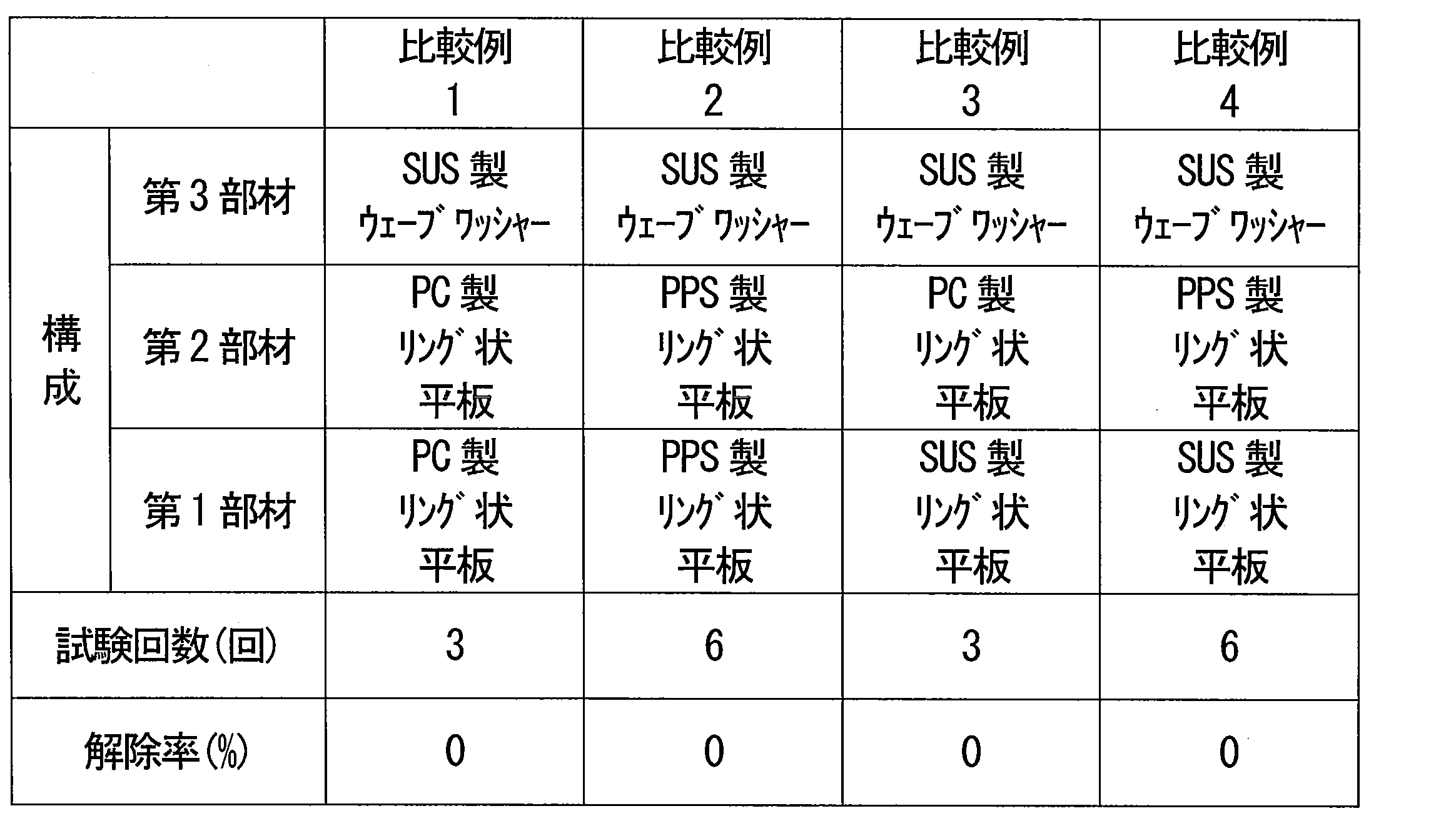
次に、実施例1の過冷却解除装置を用いて、過冷却解除試験の条件の検討を行った。詳細には、蓄熱材の過冷却状態を解除するときにおける第2部材に対する荷重の減少率Pを表4に示すように変更したことを除き、上述した方法と同じ方法によって、測定例1から5の過冷却解除試験を行った。なお、荷重の減少率Pは、過冷却解除装置の準備段階で第2部材に加えられた荷重L(MPa)に対する、荷重の減少量D(MPa)の比率を意味する。測定例1の条件は、上述した過冷却解除試験と同じである。測定例2では、過冷却解除装置の準備段階で第2部材に加えられた荷重Lを測定例1よりも大きい値に設定した。

Claims (19)
- 蓄熱材の過冷却状態を解除する過冷却解除装置であって、
前記過冷却解除装置は、互いに接触することが可能な第1部材及び第2部材を備え、
前記第1部材及び前記第2部材のそれぞれは、金属を含み、
前記第1部材及び前記第2部材の少なくとも一方に、前記第1部材の表面の少なくとも一部と前記第2部材の表面の少なくとも一部とを接触させる荷重を加え続けた状態で、前記過冷却状態が維持され、
前記過冷却状態を解除すべきときに、前記荷重を減少させる、過冷却解除装置。 - 前記第1部材及び前記第2部材のそれぞれは、板状の形状を有する、請求項1に記載の過冷却解除装置。
- 前記第1部材及び前記第2部材のそれぞれは、前記荷重を加えた状態で互いに接触する表面として、平坦面、及び、前記荷重を加えることにより接触面積が広がるように弾性変形する非平坦面からなる群より選ばれる少なくとも1つを有する、請求項2に記載の過冷却解除装置。
- 前記荷重を加える方向に直交する方向への前記第1部材及び前記第2部材の変位を規制するガイド部材をさらに備えた、請求項1から3のいずれか1項に記載の過冷却解除装置。
- 前記ガイド部材は、シリンダ及びシャフトからなる群より選ばれる少なくとも1つを含み、
前記シリンダは、前記第1部材及び前記第2部材を収容し、
前記シャフトは、前記第1部材及び前記第2部材のそれぞれに形成された貫通孔に挿入されている、請求項4に記載の過冷却解除装置。 - 第3部材をさらに備え、
前記第1部材と前記第3部材との間に前記第2部材が位置し、又は、前記第2部材と前記第3部材との間に前記第1部材が位置し、
前記第3部材は、平坦面、及び、前記荷重を加えることにより平坦性が増すように弾性変形する非平坦面からなる群より選ばれる少なくとも1つを有する、請求項1から5のいずれか1項に記載の過冷却解除装置。 - 第3部材をさらに備え、
前記第1部材と前記第3部材との間に前記第2部材が位置し、又は、前記第2部材と前記第3部材との間に前記第1部材が位置し、
前記第3部材は、樹脂部材である、請求項1から6のいずれか1項に記載の過冷却解除装置。 - 第4部材をさらに備え、
前記第3部材と前記第4部材との間に前記第1部材及び前記第2部材が位置し、
前記第4部材は、平坦面、及び、前記荷重を加えることにより平坦性が増すように弾性変形する非平坦面からなる群より選ばれる少なくとも1つを有する、請求項6又は7に記載の過冷却解除装置。 - 前記第1部材及び前記第2部材のそれぞれは、前記荷重を加えた状態で互いに接触する表面として、平坦面を有する、請求項1から8のいずれか1項に記載の過冷却解除装置。
- 前記金属の25℃における熱伝導率が225W/m・Kより小さい、請求項1から9のいずれか1項に記載の過冷却解除装置。
- 前記過冷却状態を解除すべきときに、前記荷重を減少させることにより、前記第1部材と前記第2部材との間に過冷却状態の前記蓄熱材が侵入するように、前記第1部材と前記第2部材とを相対的に変位させる、請求項1から10のいずれか1項に記載の過冷却解除装置。
- 前記第1部材及び前記第2部材のそれぞれは、前記荷重を加えた状態で互いに接触する表面に、前記蓄熱材の結晶を収容するために形成された凹部を有さない、請求項1から11のいずれか1項に記載の過冷却解除装置。
- 前記第1部材及び前記第2部材の少なくとも一方に荷重を加えるピストンをさらに備えた、請求項1から12のいずれか1項に記載の過冷却解除装置。
- 前記第1部材及び前記第2部材を収容するシリンダをさらに備えた、請求項1から13のいずれか1項に記載の過冷却解除装置。
- 請求項1から14のいずれか1項に記載の過冷却解除装置と、
水和塩、糖アルコール及び包接水和物からなる群より選ばれる少なくとも1つを含む蓄熱材と、
前記蓄熱材を収容する容器と、
を備えた、蓄熱装置。 - 請求項15に記載された蓄熱装置と、
前記蓄熱装置から放出された熱を受け取る動力機関と、
を備えた、動力装置。 - 蓄熱材の過冷却状態を解除する過冷却解除装置であって、
前記過冷却解除装置は、
互いに接触することが可能な第1部材及び第2部材と、
前記第1部材及び前記第2部材の少なくとも一方に、前記第1部材の表面の少なくとも一部と前記第2部材の表面の少なくとも一部とを接触させる荷重を加え続けて前記過冷却状態を維持し、かつ、前記過冷却状態を解除すべきときに、前記荷重を減少させる荷重負荷部材と、
を備え、
前記第1部材及び前記第2部材のそれぞれは、金属を含み、かつ板状の形状を有する、過冷却解除装置。 - 前記荷重を加える方向に直交する方向への前記第1部材及び前記第2部材の変位を規制するガイド部材をさらに備えた、請求項17に記載の過冷却解除装置。
- 前記ガイド部材は、シリンダ及びシャフトからなる群より選ばれる少なくとも1つを含み、
前記シリンダは、前記第1部材及び前記第2部材を収容し、
前記シャフトは、前記第1部材及び前記第2部材のそれぞれに形成された貫通孔に挿入されている、請求項18に記載の過冷却解除装置。
Priority Applications (3)
| Application Number | Priority Date | Filing Date | Title |
|---|---|---|---|
| CN202180049656.0A CN115836188A (zh) | 2020-07-21 | 2021-07-16 | 过冷却解除装置、蓄热装置以及动力装置 |
| US18/015,496 US12286923B2 (en) | 2020-07-21 | 2021-07-16 | Supercooling cancellation device, heat storage device, and power unit |
| JP2022537986A JP7434567B2 (ja) | 2020-07-21 | 2021-07-16 | 過冷却解除装置、蓄熱装置及び動力装置 |
Applications Claiming Priority (2)
| Application Number | Priority Date | Filing Date | Title |
|---|---|---|---|
| JP2020-124419 | 2020-07-21 | ||
| JP2020124419 | 2020-07-21 |
Publications (1)
| Publication Number | Publication Date |
|---|---|
| WO2022019246A1 true WO2022019246A1 (ja) | 2022-01-27 |
Family
ID=79729513
Family Applications (1)
| Application Number | Title | Priority Date | Filing Date |
|---|---|---|---|
| PCT/JP2021/026888 Ceased WO2022019246A1 (ja) | 2020-07-21 | 2021-07-16 | 過冷却解除装置、蓄熱装置及び動力装置 |
Country Status (4)
| Country | Link |
|---|---|
| US (1) | US12286923B2 (ja) |
| JP (1) | JP7434567B2 (ja) |
| CN (1) | CN115836188A (ja) |
| WO (1) | WO2022019246A1 (ja) |
Citations (5)
| Publication number | Priority date | Publication date | Assignee | Title |
|---|---|---|---|---|
| JPS6446582A (en) * | 1987-08-12 | 1989-02-21 | Nok Corp | Device for optionally solidifying supercooled liquid |
| JP2010105570A (ja) * | 2008-10-30 | 2010-05-13 | Honda Motor Co Ltd | 車両用暖機システム |
| JP2014009818A (ja) * | 2012-06-27 | 2014-01-20 | Furukawa Electric Co Ltd:The | 蓄熱装置 |
| JP2015158306A (ja) * | 2014-02-24 | 2015-09-03 | 古河電気工業株式会社 | 発核装置および蓄熱装置 |
| WO2020189089A1 (ja) * | 2019-03-20 | 2020-09-24 | パナソニック株式会社 | 過冷却解除装置、蓄熱装置及び動力装置 |
Family Cites Families (10)
| Publication number | Priority date | Publication date | Assignee | Title |
|---|---|---|---|---|
| JPH0543082Y2 (ja) | 1988-09-16 | 1993-10-29 | ||
| JPH02189226A (ja) * | 1989-01-12 | 1990-07-25 | Budapesti Mueszaki Egyetem | 自動車加熱装置 |
| JPH0721549Y2 (ja) * | 1989-10-05 | 1995-05-17 | エヌオーケー株式会社 | 過冷却液体の任意固化装置 |
| JP5102667B2 (ja) * | 2008-03-19 | 2012-12-19 | 本田技研工業株式会社 | 車両用暖機システム |
| JP2010054162A (ja) * | 2008-08-29 | 2010-03-11 | Honda Motor Co Ltd | 蓄熱装置及び車両用暖機システム |
| WO2013071976A1 (de) * | 2011-11-17 | 2013-05-23 | Behr Gmbh & Co. Kg | Wärmespeicher |
| DE102017200328A1 (de) * | 2016-02-10 | 2017-08-10 | Ford Global Technologies, Llc | Harnstoffbehälter als Wärmespeicher |
| JP6734085B2 (ja) * | 2016-03-18 | 2020-08-05 | パナソニック株式会社 | 蓄熱装置及び蓄熱材の結晶化を完了させる方法 |
| JP6838733B2 (ja) | 2016-12-28 | 2021-03-03 | 北川工業株式会社 | 蓄熱装置 |
| EP3599441B1 (de) * | 2018-07-25 | 2023-04-26 | GF Machining Solutions AG | Regeneriervorrichtung zum regenerieren einer kühlmitteldispersion |
-
2021
- 2021-07-16 WO PCT/JP2021/026888 patent/WO2022019246A1/ja not_active Ceased
- 2021-07-16 US US18/015,496 patent/US12286923B2/en active Active
- 2021-07-16 CN CN202180049656.0A patent/CN115836188A/zh active Pending
- 2021-07-16 JP JP2022537986A patent/JP7434567B2/ja active Active
Patent Citations (5)
| Publication number | Priority date | Publication date | Assignee | Title |
|---|---|---|---|---|
| JPS6446582A (en) * | 1987-08-12 | 1989-02-21 | Nok Corp | Device for optionally solidifying supercooled liquid |
| JP2010105570A (ja) * | 2008-10-30 | 2010-05-13 | Honda Motor Co Ltd | 車両用暖機システム |
| JP2014009818A (ja) * | 2012-06-27 | 2014-01-20 | Furukawa Electric Co Ltd:The | 蓄熱装置 |
| JP2015158306A (ja) * | 2014-02-24 | 2015-09-03 | 古河電気工業株式会社 | 発核装置および蓄熱装置 |
| WO2020189089A1 (ja) * | 2019-03-20 | 2020-09-24 | パナソニック株式会社 | 過冷却解除装置、蓄熱装置及び動力装置 |
Also Published As
| Publication number | Publication date |
|---|---|
| US12286923B2 (en) | 2025-04-29 |
| US20230250749A1 (en) | 2023-08-10 |
| JP7434567B2 (ja) | 2024-02-20 |
| CN115836188A (zh) | 2023-03-21 |
| JPWO2022019246A1 (ja) | 2022-01-27 |
Similar Documents
| Publication | Publication Date | Title |
|---|---|---|
| US10516194B2 (en) | Thermal management solution for battery pack | |
| US11058032B2 (en) | Memory module cooler with vapor chamber device connected to heat pipes | |
| JP4926889B2 (ja) | タービンエンジン用のヒートパイプベースの冷却装置 | |
| EP3220091B1 (en) | Heat storage apparatus and method of completing crystallization of heat storage material | |
| US20120279679A1 (en) | Thermal energy storage | |
| WO2015106758A1 (de) | Passive temperaturregelung von akkumulatoren | |
| JP5140013B2 (ja) | 暖機装置 | |
| WO2013186983A1 (ja) | 蓄冷熱交換器 | |
| JP2006219557A (ja) | 蓄熱材組成物、これを用いた蓄熱体及び蓄熱装置 | |
| KR101611694B1 (ko) | 관-핀 축열 증발기 | |
| WO2017159065A1 (ja) | 熱貯蔵システム | |
| Hendrayanto et al. | Experimental study on Start-Up and heat transfer characteristics in loop heat pipes with dual heat sources for battery thermal management system | |
| JP7423601B2 (ja) | 過冷却解除装置、蓄熱装置及び動力装置 | |
| JP7434567B2 (ja) | 過冷却解除装置、蓄熱装置及び動力装置 | |
| JP2010196508A (ja) | 暖機装置 | |
| US20140182319A1 (en) | Thermal energy storage for temperature regulation in electric vehicles | |
| CN110657050A (zh) | 低压排气返回系统、机动车辆和用于egr冷却器和/或egr阀的温度控制的方法 | |
| JP6674495B2 (ja) | 蓄熱システム | |
| JP2017187181A (ja) | 熱交換器及び給湯器 | |
| JP2018003616A (ja) | エンジンの排熱回収方法 | |
| WO2016098274A1 (ja) | 蓄冷熱交換器 | |
| JPS62294897A (ja) | 蓄熱式熱交換器 | |
| EP2633895A2 (en) | Sorbent canister heat exchanger | |
| WO2020250972A1 (ja) | 蓄熱装置 | |
| JPH02169994A (ja) | 蓄熱装置 |
Legal Events
| Date | Code | Title | Description |
|---|---|---|---|
| 121 | Ep: the epo has been informed by wipo that ep was designated in this application |
Ref document number: 21845477 Country of ref document: EP Kind code of ref document: A1 |
|
| ENP | Entry into the national phase |
Ref document number: 2022537986 Country of ref document: JP Kind code of ref document: A |
|
| NENP | Non-entry into the national phase |
Ref country code: DE |
|
| 122 | Ep: pct application non-entry in european phase |
Ref document number: 21845477 Country of ref document: EP Kind code of ref document: A1 |
|
| WWG | Wipo information: grant in national office |
Ref document number: 18015496 Country of ref document: US |