WO2022019295A1 - Centrale turbine à gaz - Google Patents
Centrale turbine à gaz Download PDFInfo
- Publication number
- WO2022019295A1 WO2022019295A1 PCT/JP2021/027085 JP2021027085W WO2022019295A1 WO 2022019295 A1 WO2022019295 A1 WO 2022019295A1 JP 2021027085 W JP2021027085 W JP 2021027085W WO 2022019295 A1 WO2022019295 A1 WO 2022019295A1
- Authority
- WO
- WIPO (PCT)
- Prior art keywords
- exhaust gas
- gas
- heater
- turbine
- egr
- Prior art date
- Legal status (The legal status is an assumption and is not a legal conclusion. Google has not performed a legal analysis and makes no representation as to the accuracy of the status listed.)
- Ceased
Links
Images
Classifications
-
- F—MECHANICAL ENGINEERING; LIGHTING; HEATING; WEAPONS; BLASTING
- F02—COMBUSTION ENGINES; HOT-GAS OR COMBUSTION-PRODUCT ENGINE PLANTS
- F02C—GAS-TURBINE PLANTS; AIR INTAKES FOR JET-PROPULSION PLANTS; CONTROLLING FUEL SUPPLY IN AIR-BREATHING JET-PROPULSION PLANTS
- F02C3/00—Gas-turbine plants characterised by the use of combustion products as the working fluid
- F02C3/34—Gas-turbine plants characterised by the use of combustion products as the working fluid with recycling of part of the working fluid, i.e. semi-closed cycles with combustion products in the closed part of the cycle
-
- F—MECHANICAL ENGINEERING; LIGHTING; HEATING; WEAPONS; BLASTING
- F01—MACHINES OR ENGINES IN GENERAL; ENGINE PLANTS IN GENERAL; STEAM ENGINES
- F01K—STEAM ENGINE PLANTS; STEAM ACCUMULATORS; ENGINE PLANTS NOT OTHERWISE PROVIDED FOR; ENGINES USING SPECIAL WORKING FLUIDS OR CYCLES
- F01K17/00—Using steam or condensate extracted or exhausted from steam engine plant
- F01K17/06—Returning energy of steam, in exchanged form, to process, e.g. use of exhaust steam for drying solid fuel or plant
-
- F—MECHANICAL ENGINEERING; LIGHTING; HEATING; WEAPONS; BLASTING
- F01—MACHINES OR ENGINES IN GENERAL; ENGINE PLANTS IN GENERAL; STEAM ENGINES
- F01K—STEAM ENGINE PLANTS; STEAM ACCUMULATORS; ENGINE PLANTS NOT OTHERWISE PROVIDED FOR; ENGINES USING SPECIAL WORKING FLUIDS OR CYCLES
- F01K23/00—Plants characterised by more than one engine delivering power external to the plant, the engines being driven by different fluids
- F01K23/02—Plants characterised by more than one engine delivering power external to the plant, the engines being driven by different fluids the engine cycles being thermally coupled
- F01K23/06—Plants characterised by more than one engine delivering power external to the plant, the engines being driven by different fluids the engine cycles being thermally coupled combustion heat from one cycle heating the fluid in another cycle
- F01K23/10—Plants characterised by more than one engine delivering power external to the plant, the engines being driven by different fluids the engine cycles being thermally coupled combustion heat from one cycle heating the fluid in another cycle with exhaust fluid of one cycle heating the fluid in another cycle
-
- F—MECHANICAL ENGINEERING; LIGHTING; HEATING; WEAPONS; BLASTING
- F02—COMBUSTION ENGINES; HOT-GAS OR COMBUSTION-PRODUCT ENGINE PLANTS
- F02C—GAS-TURBINE PLANTS; AIR INTAKES FOR JET-PROPULSION PLANTS; CONTROLLING FUEL SUPPLY IN AIR-BREATHING JET-PROPULSION PLANTS
- F02C6/00—Plural gas-turbine plants; Combinations of gas-turbine plants with other apparatus; Adaptations of gas-turbine plants for special use
- F02C6/18—Plural gas-turbine plants; Combinations of gas-turbine plants with other apparatus; Adaptations of gas-turbine plants for special use using the waste heat of gas-turbine plants outside the plants themselves, e.g. gas-turbine power heat plants
-
- F—MECHANICAL ENGINEERING; LIGHTING; HEATING; WEAPONS; BLASTING
- F05—INDEXING SCHEMES RELATING TO ENGINES OR PUMPS IN VARIOUS SUBCLASSES OF CLASSES F01-F04
- F05D—INDEXING SCHEME FOR ASPECTS RELATING TO NON-POSITIVE-DISPLACEMENT MACHINES OR ENGINES, GAS-TURBINES OR JET-PROPULSION PLANTS
- F05D2220/00—Application
- F05D2220/70—Application in combination with
- F05D2220/72—Application in combination with a steam turbine
-
- Y—GENERAL TAGGING OF NEW TECHNOLOGICAL DEVELOPMENTS; GENERAL TAGGING OF CROSS-SECTIONAL TECHNOLOGIES SPANNING OVER SEVERAL SECTIONS OF THE IPC; TECHNICAL SUBJECTS COVERED BY FORMER USPC CROSS-REFERENCE ART COLLECTIONS [XRACs] AND DIGESTS
- Y02—TECHNOLOGIES OR APPLICATIONS FOR MITIGATION OR ADAPTATION AGAINST CLIMATE CHANGE
- Y02E—REDUCTION OF GREENHOUSE GAS [GHG] EMISSIONS, RELATED TO ENERGY GENERATION, TRANSMISSION OR DISTRIBUTION
- Y02E20/00—Combustion technologies with mitigation potential
- Y02E20/16—Combined cycle power plant [CCPP], or combined cycle gas turbine [CCGT]
Definitions
- the exhaust gas may contain water (moisture).
- water moisture
- white smoke is generated when the exhaust gas is discharged.
- the exhaust gas directly drops near the exhaust gas outlet and a small amount of nitrogen oxides in the exhaust gas are also accompanied. It has been demanded. Therefore, in the technique according to Patent Document 1 below, a method is adopted in which the used absorption liquid is heated and regenerated by the heat of the exhaust gas, and the exhaust gas is heated by using the heat of the regenerated absorption liquid. As a result, the water in the exhaust gas evaporates, and it is said that the generation of white smoke can be suppressed.
- the present disclosure has been made to solve the above problems, and an object of the present disclosure is to provide a gas turbine plant capable of further suppressing the generation of white smoke.
- the gas turbine plant includes a gas turbine, an exhaust heat recovery boiler that generates steam by exchanging heat between the exhaust gas of the gas turbine and water, and the exhaust gas.
- the absorption tower that recovers the contained carbon dioxide, the EGR line that extracts a part of the exhaust gas and guides it to the intake side of the gas turbine, and the steam taken out from the exhaust heat recovery boiler are used as heat media.
- An exhaust gas heater that heats the exhaust gas by exchanging heat between the heat medium and the exhaust gas that has passed through the absorption tower, and the exhaust gas and the exhaust gas heating that are provided on the EGR line and flow through the EGR line.
- the EGR heater is provided to heat the exhaust gas flowing through the EGR line by exchanging heat with the heat medium discharged from the vessel.
- the generation of white smoke can be further suppressed.
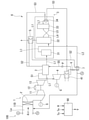
- the gas turbine plant 100 includes a gas turbine 1, an exhaust heat recovery boiler 2, a steam turbine 4, an exhaust gas treatment facility 6, an EGR line L2, an EGR heater 7, and a control device. It is equipped with 90.
- the gas turbine 1 has a compressor 11, a combustor 12, and a turbine 13.
- the compressor 11 compresses the outside air guided through the intake line La to generate high-pressure air.
- an outside air temperature measuring unit To for measuring the temperature of the outside air and an outside air humidity measuring unit H for measuring the humidity of the outside air are provided on the intake line La.
- an intake duct 11D and a filter F arranged in the intake duct 11D are provided.
- the combustor 12 produces high-temperature and high-pressure combustion gas by mixing fuel with the high-pressure air generated by the compressor 11 and burning the fuel.
- the turbine 13 is driven by this combustion gas.
- the rotational energy of the turbine 13 is taken out from the shaft end and used for driving, for example, the generator G.
- the exhaust gas discharged from the turbine 13 is recovered by the exhaust line L1 and sent to the exhaust heat recovery boiler 2.
- the exhaust heat recovery boiler 2 generates superheated steam by exchanging heat between the exhaust gas flowing in the exhaust line L1 and water. This superheated steam is sent to the steam turbine 4 through the first line S1 and used to drive the steam turbine 4. The rotational energy of the steam turbine 4 is used, for example, to drive the generator G.
- the steam discharged from the steam turbine 4 is recovered by the condenser 41. In the condenser 41, steam is condensed to generate water by exchanging heat with a medium guided from the outside. The water generated by the condenser 41 is supplied to the exhaust heat recovery boiler 2 through the fifth line S5.
- An exhaust gas treatment facility 6 is provided on the exhaust line L1 on the downstream side of the exhaust heat recovery boiler 2.
- the exhaust gas treatment facility 6 is provided to keep the exhaust gas flowing in the exhaust line L1 in a clean state and dissipate it to the outside air.
- the exhaust gas treatment equipment 6 includes a carbon dioxide recovery device 3 and an exhaust gas heater 5.
- the carbon dioxide recovery device 3 is a device for recovering and removing carbon dioxide contained in the exhaust gas.
- the carbon dioxide capture device 3 has a cooling tower 31 (quencher), an absorption tower 32, and a regeneration tower 33.
- the cooling tower 31 is a facility for cooling the exhaust gas flowing through the exhaust line L1 prior to the recovery of carbon dioxide in the absorption tower 32 described later.
- the temperature of the exhaust gas flowing through the exhaust line L1 is about 90 ° C.
- the exhaust gas is cooled to about 30 ° C. in the cooling tower 31.
- the exhaust gas cooled by the cooling tower 31 is sent to the absorption tower 32 through the exhaust line L1.
- the absorption tower 32 has a cylindrical shape extending in the vertical direction, and an exhaust line L1 extending from the cooling tower 31 is connected to the lower portion thereof.
- an absorption liquid capable of chemically bonding with carbon dioxide flows from above to below.
- an absorbent include an aqueous solution of an amine containing monoethanolamine (MEA), diethanolamine (DEA), triethanolamine (TEA), diisopropanolamine (DIPA), and methyldiethanolamine (MDEA).
- An organic solvent containing no water, a mixture thereof, and an amino acid-based aqueous solution are preferably used.
- the exhaust gas flowing into the lower part of the absorption tower 32 rises in the absorption tower 32 while contacting the absorption liquid flowing from above. At this time, carbon dioxide contained in the exhaust gas is chemically absorbed by the absorbing liquid. The residual exhaust gas from which carbon dioxide has been removed flows into the exhaust line L1 again from the upper part of the absorption tower 32.
- the absorption liquid that has absorbed carbon dioxide is sent to the regeneration tower 33 through the absorption liquid recovery line L4 connected to the lower part of the absorption tower 32.
- the regeneration tower 33 is a device for regenerating (separating carbon dioxide) the absorbing liquid in a state where carbon dioxide has been absorbed.
- a third line S3 through which steam taken out from the exhaust heat recovery boiler 2 described above flows is connected to the regeneration tower 33.
- a reboiler 34 is provided on the third line S3. Steam from the exhaust heat recovery boiler 2 is supplied to the reboiler 34 through the third line S3. In the reboiler 34, a part of the water contained in the absorbing liquid is heated by the heat exchange with the steam to become stripping steam.
- the stripping steam is sent into the regeneration tower 33 through the absorption liquid extraction line L7.
- the stripping steam comes into contact with the pre-regeneration absorption liquid supplied from the absorption liquid recovery line L4.
- carbon dioxide is dissipated from the absorption liquid before regeneration, and the absorption liquid is regenerated (the state does not contain carbon dioxide).
- the carbon dioxide emitted from the absorption liquid before regeneration is sent from the regeneration tower 33 to a carbon dioxide compression device (not shown). Further, the steam discharged from the reboiler 34 is sent to the above-mentioned condenser 41 through the third line S3.
- a part of the absorbed liquid after regeneration (that is, the component that did not become stripping steam) is sent to the absorbent liquid supply line L5 connected to the lower part of the regeneration tower 33.
- a heat exchanger, a pump, and a cooler (not shown) are provided on the absorbent liquid supply line L5.
- the regenerated absorption liquid is supplied from the regeneration tower 33 to the heat exchanger.
- the absorbed liquid after regeneration is appropriately cooled to a temperature suitable for absorbing carbon dioxide.
- the regenerated absorption liquid at a low temperature is supplied to the upper part of the absorption tower 32.
- the exhaust gas heater 5 heats the exhaust gas in order to suppress whitening of the exhaust gas discharged from the carbon dioxide recovery device 3 via the exhaust line L1.
- the exhaust gas heater 5 is a heat exchanger. Steam (for example, 200 ° C. to 230 ° C.) taken out through the second line S2 branched from the third line S3 described above flows through the exhaust gas heater 5 as a heat medium. That is, the exhaust gas heater 5 uses the steam taken out from the exhaust heat recovery boiler 2 as a heat medium.
- the "steam taken out from the exhaust heat recovery boiler 2" is the steam directly taken out from the exhaust heat recovery boiler 2 and the steam extracted from the exhaust heat recovery boiler 2 after being used for driving the steam turbine 4. Contains at least one of the steam.
- the steam as a heat medium that has passed through the exhaust gas heater 5 is sent as a heat medium to the EGR heater 7, which will be described later, through the second line S2.
- the heat medium may be in a liquid phase state (water) or a gas phase state (steam).
- the EGR line L2 draws at least a part of the exhaust gas that has passed through the cooling tower 31 of the carbon dioxide recovery device 3 and guides it to the intake side (compressor 11) of the gas turbine 1. More specifically, one end of the EGR line L2 is provided on the upstream side (that is, the side in contact with the outside air) of the filter F in the intake duct 11D described above.
- an EGR heater 7 and an exhaust gas temperature measuring unit Te are provided in order from the cooling tower 31 side toward the gas turbine 1 side.
- the EGR heater 7 is a heat exchanger. In the EGR heater 7, heat exchange is performed between the heat medium guided from the exhaust gas heater 5 and the exhaust gas through the second line S2 described above.
- the exhaust gas that has passed through the EGR heater 7 is heated.
- the temperature of the exhaust gas supplied from the cooling tower 31 is about 30 ° C.
- it is desirable that the temperature of the exhaust gas after passing through the EGR heater 7 is about 40 ° C.
- the heat medium that has passed through the EGR heater 7 is guided to the condenser 41 through the second line S2.
- a valve device V (supply amount adjusting unit) is provided between the EGR heater 7 and the condenser 41 on the second line S2.
- the valve device V is a flow rate adjusting valve.
- the opening degree of the valve device V is the humidity of the exhaust gas measured by the temperature of the exhaust gas measured by the exhaust gas temperature measuring unit Te, the temperature of the outside air measured by the outside air temperature measuring unit To, and the outside air measured by the outside air humidity measuring unit H. It is determined and adjusted by the control device 90 based on the humidity of the above.
- the exhaust gas that has passed through the absorption tower 32 is heated by the exhaust gas heater 5.
- the moisture contained in the exhaust gas evaporates, so that the possibility of white smoke when the exhaust gas is released to the outside can be further reduced.
- a part of the exhaust gas discharged from the cooling tower 31 is guided (recirculated) to the intake side of the gas turbine 1 through the EGR line L2.
- the exhaust gas contains moisture, moisture may adhere to the filter F provided in the intake duct 11D of the compressor 11, and the intake resistance may increase. Further, such water may become water droplets and collide with the moving blades of the compressor 11 to generate erosion.
- the EGR line L2 concentrates not only CO2 but also water, the possibility of white smoke tends to increase.
- the exhaust gas flowing through the EGR line L2 is heated by the EGR heater 7.
- the humidity of the exhaust gas is reduced, so that the adhesion of water to the filter F is suppressed.
- an increase in intake resistance can be suppressed.
- the amount of the heat medium supplied to the EGR heater 7 is adjusted based on the temperature of the exhaust gas flowing through the EGR line L2.
- the heating amount of the exhaust gas by the EGR heater 7 can be changed.
- the temperature of the exhaust gas supplied to the gas turbine 1 is too high, the amount of the heat medium is reduced by reducing the opening degree of the valve device V as the supply amount adjusting unit, and the temperature is lowered. Can be changed to.
- the amount of heat medium used can be reduced and the efficiency of the plant can be improved.
- the temperature of the exhaust gas is too low, the temperature can be changed in the direction of increasing by increasing the amount of the heat medium.
- the temperature of the exhaust gas supplied to the gas turbine 1 is optimized, and the moisture content can be kept from being saturated in the mixed gas of the outside air and the exhaust gas.
- the amount of the heat medium supplied to the EGR heater 7 is adjusted based on the temperature of the outside air supplied to the gas turbine 1 in addition to the temperature of the exhaust gas flowing through the EGR line L2.
- the amount of the heat medium is increased by increasing the opening degree of the valve device V as the supply amount adjusting unit, and the temperature of the exhaust gas is raised.
- the temperature of the exhaust gas supplied to the gas turbine 1 is optimized, the temperature of the mixed gas of the outside air and the exhaust gas exceeds the dew point, and the moisture content can be not saturated.
- the amount of the heat medium supplied to the EGR heater 7 is adjusted based on the humidity of the outside air in addition to the temperature of the exhaust gas flowing through the EGR line L2 and the temperature of the outside air. For example, when the humidity of the outside air is excessively high, the temperature of the exhaust gas is raised by increasing the amount of the heat medium supplied to the EGR heater 7. On the other hand, when the humidity of the outside air is excessively low, the temperature of the exhaust gas is lowered by reducing the amount of the heat medium supplied to the EGR heater 7. As a result, the temperature and humidity of the exhaust gas supplied to the gas turbine 1 are optimized, and the moisture content can be kept from being saturated in the mixed gas of the outside air and the exhaust gas.
- the first embodiment of the present disclosure has been described above. It is possible to make various changes and modifications to the above configuration as long as it does not deviate from the gist of the present disclosure.
- the exhaust gas temperature measuring unit Te and the outside air humidity measuring unit H are provided on the EGR line and the outside air temperature measuring unit To is provided on the intake line La has been described.
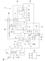
- the steam turbine 4 has a high-pressure steam turbine 4H and a low-pressure steam turbine 4L.
- the low-pressure steam turbine 4L and the high-pressure steam turbine 4H may be connected coaxially or may be independent of each other.
- the high-pressure steam turbine 4H is driven by steam guided from the exhaust heat recovery boiler 2 through the first line S1.
- the steam that has passed through the high-pressure steam turbine 4H is guided to the low-pressure steam turbine 4L to drive the low-pressure steam turbine 4L.
- the steam that has passed through the low-pressure steam turbine 4L is sent to the condenser 41.
- the sixth line S6 is connected to the middle stage of the high pressure steam turbine 4H.
- the high-temperature steam extracted by the sixth line S6 (for example, 250 ° C. to 350 ° C.) is sent as a heat medium to the auxiliary exhaust gas heater 5B described later. It is also possible to adopt a configuration in which the steam turbine 4 has only one turbine. In this case, it is desirable that the sixth line S6 is connected to the high pressure side stage of the steam turbine 4.
- the auxiliary exhaust gas heater 5B is provided on the downstream side of the exhaust gas heater 5 in the exhaust line L1.
- the auxiliary exhaust gas heater 5B is a heat exchanger that exchanges heat between the steam extracted from the high-pressure steam turbine 4H and the exhaust gas flowing through the exhaust line L1.
- the exhaust gas that has passed through the exhaust gas heater 5 is further heated by the auxiliary exhaust gas heater 5B.
- the moisture content in the exhaust gas is further reduced, and the possibility of white smoke formation can be further reduced.
- the gas turbine plant 100 includes a gas turbine 1, an exhaust heat recovery boiler 2 that generates steam by exchanging heat between the exhaust gas of the gas turbine 1 and water, and the exhaust gas.
- the absorption tower 32 that recovers the carbon dioxide contained in the exhaust gas
- the EGR line L2 that extracts a part of the exhaust gas and guides it to the intake side of the gas turbine 1, and the steam taken out from the exhaust heat recovery boiler 2.
- the exhaust gas heater 5 that heats the exhaust gas by exchanging heat between the heat medium and the exhaust gas that has passed through the absorption tower 32, and the EGR line L2 provided on the EGR line L2.
- the EGR heater 7 is provided to heat the exhaust gas flowing through the EGR line L2 by exchanging heat between the flowing exhaust gas and the heat medium discharged from the exhaust gas heater 5.
- the exhaust gas that has passed through the absorption tower 32 is heated by the exhaust gas heater 5.
- the moisture contained in the exhaust gas evaporates, so that the possibility of white smoke when the exhaust gas is released to the outside can be reduced.
- the gas turbine plant 100 further includes a quencher (cooling tower 31) for cooling the exhaust gas exhausted from the exhaust heat recovery boiler 2, and the EGR line L2 is discharged from the quencher. A part of the exhaust gas is extracted and guided to the intake side of the gas turbine 1.
- a quencher cooling tower 31 for cooling the exhaust gas exhausted from the exhaust heat recovery boiler 2, and the EGR line L2 is discharged from the quencher. A part of the exhaust gas is extracted and guided to the intake side of the gas turbine 1.
- the gas turbine plant 100 according to the third aspect is provided on the intake side of the gas turbine with respect to the EGR heater 7 on the EGR line L2, and the temperature of the exhaust gas flowing through the EGR line L2 is adjusted. Further, an exhaust gas temperature measuring unit Te to be measured and a supply amount adjusting unit (valve device V) for adjusting the amount of the heat medium supplied to the EGR heater 7 based on the temperature of the exhaust gas are further provided.
- the amount of the heat medium supplied to the EGR heater 7 is adjusted based on the temperature of the exhaust gas flowing through the EGR line L2.
- the heating amount of the exhaust gas by the EGR heater 7 can be changed.
- the supply amount adjusting unit reduces the amount of the heat medium, so that the temperature can be changed in the direction of lowering.
- the supply amount adjusting unit can increase the amount of the heat medium to change the temperature in the direction of increasing.
- the gas turbine plant 100 according to the fourth aspect further includes an outside air temperature measuring unit To for measuring the temperature of the outside air supplied to the gas turbine 1, and the supply amount adjusting unit (valve device V) includes the supply amount adjusting unit (valve device V).
- the amount of the heat medium supplied to the EGR heater 7 is adjusted based on the temperature of the exhaust gas and the temperature of the outside air.
- the amount of the heat medium supplied to the EGR heater 7 is adjusted based on the temperature of the outside air supplied to the gas turbine 1 in addition to the temperature of the exhaust gas flowing through the EGR line L2.
- the supply amount adjusting unit reduces the amount of the heat medium to bring the temperature of the exhaust gas closer to the temperature of the outside air.
- the temperature of the exhaust gas supplied to the gas turbine 1 is optimized, and the moisture content can be kept from being saturated in the mixed gas of the outside air and the exhaust gas.
- the gas turbine plant 100 further includes an outside air humidity measuring unit (H) for measuring the humidity of the outside air sucked by the gas turbine, and the supply amount adjusting unit (valve device V) is the above.
- the amount of the heat medium supplied to the EGR heater is adjusted based on the temperature of the exhaust gas, the temperature of the outside air, and the humidity of the outside air.
- the amount of the heat medium supplied to the EGR heater 7 is adjusted based on the temperature of the exhaust gas flowing through the EGR line L2 and the temperature of the outside air as well as the humidity of the outside air.
- the temperature and humidity of the exhaust gas supplied to the gas turbine 1 are optimized, and the moisture content can be kept from being saturated in the mixed gas of the outside air and the exhaust gas.
- the gas turbine plant 100 has passed through the steam turbine 4 driven by the steam generated in the exhaust heat recovery boiler 2, the steam extracted from the steam turbine 4, and the absorption tower 32.
- An auxiliary exhaust gas heater 5B that heats the exhaust gas by exchanging heat with the exhaust gas is further provided.
- the exhaust gas that has passed through the exhaust gas heater 5 is further heated by the auxiliary exhaust gas heater 5B.
- the moisture content in the exhaust gas is further reduced, and the possibility of white smoke can be further reduced.
- the steam turbine 4 includes a high-pressure steam turbine 4H and a low-pressure steam turbine 4L driven by steam discharged from the high-pressure steam turbine 4H, and the auxiliary.
- the exhaust gas heater 5B is provided on the downstream side of the exhaust gas heater 5 in the flow direction of the exhaust gas, and includes steam extracted from the high-pressure steam turbine 4H and exhaust gas that has passed through the exhaust gas heater 5. By exchanging heat with the turbine, the exhaust gas is further heated.
- the exhaust gas that has passed through the exhaust gas heater 5 is further heated by the auxiliary exhaust gas heater 5B.
- the moisture content in the exhaust gas is further reduced, and the possibility of white smoke can be further reduced.
- This disclosure relates to a gas turbine plant. According to the present disclosure, the generation of white smoke can be further suppressed.
Landscapes
- Engineering & Computer Science (AREA)
- Chemical & Material Sciences (AREA)
- Combustion & Propulsion (AREA)
- Mechanical Engineering (AREA)
- General Engineering & Computer Science (AREA)
- Life Sciences & Earth Sciences (AREA)
- Sustainable Development (AREA)
- Treating Waste Gases (AREA)
- Engine Equipment That Uses Special Cycles (AREA)
- Gas Separation By Absorption (AREA)
- Carbon And Carbon Compounds (AREA)
Abstract
L'invention concerne une centrale turbine à gaz qui est pourvue : d'une turbine à gaz; d'une chaudière de récupération de chaleur perdue qui génère de la vapeur par échange de chaleur entre les gaz d'échappement provenant de la turbine à gaz et de l'eau; d'une tour d'absorption qui récupère le dioxyde de carbone contenu dans le gaz d'échappement; d'une conduite de recirculation des gaz d'échappement qui prélève une partie du gaz d'échappement et la guide vers le côté d'admission de la turbine à gaz; d'un dispositif de chauffage de gaz d'échappement qui utilise de la vapeur extraite de la chaudière de récupération de chaleur perdue en tant que milieu de chaleur pour chauffer le gaz d'échappement qui a traversé la tour d'absorption, par échange de chaleur entre le milieu de chaleur et le gaz d'échappement; et d'un dispositif de chauffage RGE qui est disposé sur la ligne RGE, et qui chauffe le gaz d'échappement traversant la ligne de RGE en échangeant de la chaleur entre les gaz d'échappement passant à travers ladite ligne de RGE et le milieu de chaleur évacué du dispositif de chauffage de gaz d'échappement.
Priority Applications (2)
| Application Number | Priority Date | Filing Date | Title |
|---|---|---|---|
| US18/015,788 US20230258124A1 (en) | 2020-07-20 | 2021-07-20 | Gas turbine plant |
| EP21846784.3A EP4166764B1 (fr) | 2020-07-20 | 2021-07-20 | Centrale turbine à gaz |
Applications Claiming Priority (2)
| Application Number | Priority Date | Filing Date | Title |
|---|---|---|---|
| JP2020123749A JP7491760B2 (ja) | 2020-07-20 | 2020-07-20 | ガスタービンプラント |
| JP2020-123749 | 2020-07-20 |
Publications (1)
| Publication Number | Publication Date |
|---|---|
| WO2022019295A1 true WO2022019295A1 (fr) | 2022-01-27 |
Family
ID=79729154
Family Applications (1)
| Application Number | Title | Priority Date | Filing Date |
|---|---|---|---|
| PCT/JP2021/027085 Ceased WO2022019295A1 (fr) | 2020-07-20 | 2021-07-20 | Centrale turbine à gaz |
Country Status (4)
| Country | Link |
|---|---|
| US (1) | US20230258124A1 (fr) |
| EP (1) | EP4166764B1 (fr) |
| JP (2) | JP7491760B2 (fr) |
| WO (1) | WO2022019295A1 (fr) |
Cited By (2)
| Publication number | Priority date | Publication date | Assignee | Title |
|---|---|---|---|---|
| WO2025182185A1 (fr) * | 2024-02-26 | 2025-09-04 | 三菱重工業株式会社 | Installation et procédé de commande d'installation |
| EP4536943A4 (fr) * | 2022-07-29 | 2026-04-22 | Ge Vernova Tech Gmbh | Centrale à cycle combiné comportant un éjecteur de recirculation des gaz d'échappement |
Citations (4)
| Publication number | Priority date | Publication date | Assignee | Title |
|---|---|---|---|---|
| JP2007170307A (ja) * | 2005-12-22 | 2007-07-05 | Mitsubishi Heavy Ind Ltd | ガスタービンコンバインドサイクルプラント及び発電方法。 |
| JP2009247932A (ja) | 2008-04-02 | 2009-10-29 | Chiyoda Kako Kensetsu Kk | 排ガス熱源を利用した二酸化炭素の除去方法 |
| JP2013029305A (ja) * | 2011-07-27 | 2013-02-07 | Alstom Technology Ltd | 排気ガス再循環を備えるガスタービン発電機を作動するために方法 |
| JP2020123749A (ja) | 2020-05-07 | 2020-08-13 | 株式会社Fuji | ノズル管理装置 |
Family Cites Families (11)
| Publication number | Priority date | Publication date | Assignee | Title |
|---|---|---|---|---|
| JP3882107B2 (ja) * | 2001-09-04 | 2007-02-14 | 大阪瓦斯株式会社 | ガスタービン組込みボイラ |
| DE102005015151A1 (de) * | 2005-03-31 | 2006-10-26 | Alstom Technology Ltd. | Gasturbinenanlage |
| EP2248999A1 (fr) * | 2008-12-24 | 2010-11-10 | Alstom Technology Ltd | Centrale électrique avec un système de capture de CO2 |
| CH700310A1 (de) * | 2009-01-23 | 2010-07-30 | Alstom Technology Ltd | Verfahren zur CO2 Abscheidung aus einem Kombikraftwerk und Kombikraftwerk mit einer Gasturbine mit Strömungsteilung und Rezirkulation. |
| EP2290202A1 (fr) * | 2009-07-13 | 2011-03-02 | Siemens Aktiengesellschaft | Installation de cogénération et procédé de cogénération |
| JP2013540229A (ja) * | 2010-10-05 | 2013-10-31 | アルストム テクノロジー リミテッド | Co2捕捉を備えたコンバインドサイクル発電所及びこれを運転する方法 |
| WO2012104202A1 (fr) * | 2011-02-01 | 2012-08-09 | Alstom Technology Ltd | Centrale à cycle mixte comprenant une installation de capture de co2 |
| CA2858631C (fr) * | 2011-12-19 | 2017-01-10 | Alstom Technology Ltd. | Regulation de la composition du gaz dans une centrale electrique a turbine a gaz avec recirculation d'effluents gazeux |
| EP2636870B1 (fr) * | 2012-03-05 | 2018-05-30 | General Electric Technology GmbH | Préparation de gaz d'échappement à partir d'une turbine à gaz pour la recirculation de gaz d'échappement |
| US20140241965A1 (en) | 2013-02-22 | 2014-08-28 | Mitsubishi Heavy Industries, Ltd. | Exhaust gas treatment system and exhaust gas treatment method |
| US9885290B2 (en) * | 2014-06-30 | 2018-02-06 | General Electric Company | Erosion suppression system and method in an exhaust gas recirculation gas turbine system |
-
2020
- 2020-07-20 JP JP2020123749A patent/JP7491760B2/ja active Active
-
2021
- 2021-07-20 WO PCT/JP2021/027085 patent/WO2022019295A1/fr not_active Ceased
- 2021-07-20 US US18/015,788 patent/US20230258124A1/en not_active Abandoned
- 2021-07-20 EP EP21846784.3A patent/EP4166764B1/fr active Active
-
2024
- 2024-05-16 JP JP2024080426A patent/JP7720949B2/ja active Active
Patent Citations (4)
| Publication number | Priority date | Publication date | Assignee | Title |
|---|---|---|---|---|
| JP2007170307A (ja) * | 2005-12-22 | 2007-07-05 | Mitsubishi Heavy Ind Ltd | ガスタービンコンバインドサイクルプラント及び発電方法。 |
| JP2009247932A (ja) | 2008-04-02 | 2009-10-29 | Chiyoda Kako Kensetsu Kk | 排ガス熱源を利用した二酸化炭素の除去方法 |
| JP2013029305A (ja) * | 2011-07-27 | 2013-02-07 | Alstom Technology Ltd | 排気ガス再循環を備えるガスタービン発電機を作動するために方法 |
| JP2020123749A (ja) | 2020-05-07 | 2020-08-13 | 株式会社Fuji | ノズル管理装置 |
Non-Patent Citations (1)
| Title |
|---|
| See also references of EP4166764A4 |
Cited By (2)
| Publication number | Priority date | Publication date | Assignee | Title |
|---|---|---|---|---|
| EP4536943A4 (fr) * | 2022-07-29 | 2026-04-22 | Ge Vernova Tech Gmbh | Centrale à cycle combiné comportant un éjecteur de recirculation des gaz d'échappement |
| WO2025182185A1 (fr) * | 2024-02-26 | 2025-09-04 | 三菱重工業株式会社 | Installation et procédé de commande d'installation |
Also Published As
| Publication number | Publication date |
|---|---|
| JP2022020324A (ja) | 2022-02-01 |
| EP4166764A4 (fr) | 2023-11-22 |
| EP4166764B1 (fr) | 2024-10-23 |
| EP4166764A1 (fr) | 2023-04-19 |
| US20230258124A1 (en) | 2023-08-17 |
| JP7491760B2 (ja) | 2024-05-28 |
| JP7720949B2 (ja) | 2025-08-08 |
| JP2024100856A (ja) | 2024-07-26 |
Similar Documents
| Publication | Publication Date | Title |
|---|---|---|
| JP5100294B2 (ja) | 発電プラントエミッションを低減するためのシステム | |
| US12409411B2 (en) | Exhaust gas processing equipment and gas turbine plant | |
| JP7412102B2 (ja) | ガスタービンプラント | |
| JP7330718B2 (ja) | ガスタービンプラント、及びその排出二酸化炭素回収方法 | |
| JP7720949B2 (ja) | ガスタービンプラント | |
| CN101778663A (zh) | 从气流中回收气体组分的方法和吸收剂成分 | |
| US20180216532A1 (en) | System and method for treating exhaust gas | |
| JP2010112377A (ja) | ガスタービンシステム内の腐食を低減するためのシステム及び方法 | |
| JP4929227B2 (ja) | 高湿分空気利用ガスタービンシステム | |
| US20250347238A1 (en) | Exhaust gas processing equipment and gas turbine plant | |
| AU2013313605B2 (en) | Heat recovery system and heat recovery method | |
| WO2014129391A1 (fr) | Procédé et système de récupération de co2 | |
| WO2008090166A1 (fr) | Procédé pour obtenir une puissance de sortie constante dans une centrale électrique intégrée à une unité de capture de dioxyde de carbone | |
| US20250345746A1 (en) | Exhaust gas processing equipment and gas turbine plant |
Legal Events
| Date | Code | Title | Description |
|---|---|---|---|
| 121 | Ep: the epo has been informed by wipo that ep was designated in this application |
Ref document number: 21846784 Country of ref document: EP Kind code of ref document: A1 |
|
| ENP | Entry into the national phase |
Ref document number: 2021846784 Country of ref document: EP Effective date: 20230110 |
|
| NENP | Non-entry into the national phase |
Ref country code: DE |