WO2022024196A1 - Système de communication, procédé de commande de destination de connexion, dispositif de commande, et programme - Google Patents
Système de communication, procédé de commande de destination de connexion, dispositif de commande, et programme Download PDFInfo
- Publication number
- WO2022024196A1 WO2022024196A1 PCT/JP2020/028756 JP2020028756W WO2022024196A1 WO 2022024196 A1 WO2022024196 A1 WO 2022024196A1 JP 2020028756 W JP2020028756 W JP 2020028756W WO 2022024196 A1 WO2022024196 A1 WO 2022024196A1
- Authority
- WO
- WIPO (PCT)
- Prior art keywords
- terminal
- dead zone
- dead
- control device
- connection destination
- Prior art date
- Legal status (The legal status is an assumption and is not a legal conclusion. Google has not performed a legal analysis and makes no representation as to the accuracy of the status listed.)
- Ceased
Links
Images







Classifications
-
- H—ELECTRICITY
- H04—ELECTRIC COMMUNICATION TECHNIQUE
- H04W—WIRELESS COMMUNICATION NETWORKS
- H04W36/00—Hand-off or reselection arrangements
- H04W36/24—Reselection being triggered by specific parameters
- H04W36/30—Reselection being triggered by specific parameters by measured or perceived connection quality data
- H04W36/302—Reselection being triggered by specific parameters by measured or perceived connection quality data due to low signal strength
-
- H—ELECTRICITY
- H04—ELECTRIC COMMUNICATION TECHNIQUE
- H04W—WIRELESS COMMUNICATION NETWORKS
- H04W36/00—Hand-off or reselection arrangements
- H04W36/0005—Control or signalling for completing the hand-off
- H04W36/0083—Determination of parameters used for hand-off, e.g. generation or modification of neighbour cell lists
- H04W36/00835—Determination of neighbour cell lists
-
- H—ELECTRICITY
- H04—ELECTRIC COMMUNICATION TECHNIQUE
- H04W—WIRELESS COMMUNICATION NETWORKS
- H04W36/00—Hand-off or reselection arrangements
- H04W36/24—Reselection being triggered by specific parameters
- H04W36/32—Reselection being triggered by specific parameters by location or mobility data, e.g. speed data
- H04W36/322—Reselection being triggered by specific parameters by location or mobility data, e.g. speed data by location data
-
- H—ELECTRICITY
- H04—ELECTRIC COMMUNICATION TECHNIQUE
- H04W—WIRELESS COMMUNICATION NETWORKS
- H04W64/00—Locating users or terminals or network equipment for network management purposes, e.g. mobility management
Definitions
- the present invention relates to a technique for avoiding deterioration of communication quality and communication interruption in a wireless communication system.
- Non-Patent Document 1 Standardization of a wireless communication system called 5G (for example, Non-Patent Document 1) is being promoted in 3GPP, and 5G communication services have been started.
- L5G local 5G
- 5G has features such as ultra-high speed, ultra-low delay, and multiple simultaneous connections, and is expected to be used for various wireless access. Especially in L5G, the use of mission-critical applications is expected, and maintenance of communication quality is required more strictly. Further, since the introduction cost of L5G is higher than that of other wireless systems (wireless LAN), it is expected that the introduction will be limited to an area such as limiting the number of base stations.
- the radio wave has high straightness, and there is a possibility that an area or a dead zone where the radio wave is difficult to reach may occur due to the pillars or obstacles of the building. .. If the terminal (UE) enters an area where radio waves are difficult to reach or a dead zone, communication quality may deteriorate (including communication interruption).
- the present invention has been made in view of the above points, and an object of the present invention is to provide a technique for avoiding deterioration of communication quality caused by a terminal entering a dead zone in a wireless communication system.
- a communication system having a terminal that wirelessly communicates with a base station and a control device.
- the terminal includes a transmission unit that transmits the position information of the terminal.
- the control device is The dead zone setting section that sets the area around the dead zone as the dead zone, and the dead zone setting section.
- An information gathering unit that acquires the location information of the terminal, By comparing the position information of the terminal with the dead reserve area, it is determined whether or not the terminal exists in the dead reserve area, and when it is determined that the terminal exists in the dead reserve area, the said.
- a communication system including a connection destination control unit that executes control for switching a connection destination of a terminal is provided.
- a technology for avoiding deterioration of communication quality caused by a terminal entering a dead zone is provided.
- the "dead zone” is an area where radio waves from the base station are difficult to reach.
- the “area where radio waves are difficult to reach” is, for example, an area where only radio waves with power equal to or lower than a certain threshold can reach (including areas where radio waves do not reach at all).
- the terminal will be referred to as a UE.
- UE is an abbreviation for User Equipment.
- base station 1 and base station 2 exist, and their respective radio wave reach ranges are shown as area A and area B, respectively.
- the UE 10 is connected to the base station 1.
- a shield C such as a wall exists at the position shown in the figure, and the area behind the shield C when viewed from the base station 1 is a dead zone.
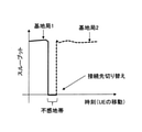
- FIG. 2 shows a change in communication quality (for example, throughput in UE 10) when the UE 10 passes through a dead zone and moves to area B. As shown in FIG. 2, the throughput becomes 0 during the period when the UE 10 passes through the dead zone.
- a change in communication quality for example, throughput in UE 10
- a dead zone is set around the dead zone, and the control device 100 described later sets the dead zone of the UE 10.
- the UE 10 is made to switch the connection to another line (another base station, etc.) in advance and to perform redundancy by connecting a plurality of lines.
- FIG. 3 shows an example of the overall configuration of the communication system according to the present embodiment.
- this system has a control device 100, a carrier network 200, a carrier network 300, and an L5G operator network 400, which are connected to the Internet 500.
- the UE 10 wirelessly communicates with the base station 430 or the like of the L5G operator network 400 according to its position.
- the carrier network 200 has an LTE core network 210 and a base station 220. Although only one base station is shown in each network in FIG. 3, this is for convenience of illustration, and a large number of base stations may actually exist.
- the carrier network 300 has a 5G core network 310 and a base station 320.
- the L5G operator network 400 has an integrated SW410, an L5G core network 420, a base station 430, and a wireless LAN-AP440.
- the network may include a plurality of wireless systems such as a wireless LAN-AP and an IoT terminal.
- FIG. 3 shows, as an example, an example in which a wireless LAN-AP440 exists in the L5G operator network 400.
- the control device 100 is a device that executes the control process according to the present invention, and is a virtual server provided on the cloud or a physical server provided on the physical network.
- the placement location of the control device 100 is not limited to a specific location, but the placement location may be determined according to the control range. For example, when it is assumed that the UE 10 connected to the L5G business network 400 is controlled, the control device 100 may be installed at a location close to the L5G business network 400.
- the information from the UE 10 is transmitted to the control device 100 via the wireless system (LTE, 5G, L5G, wireless LAN, IoT terminal, etc.) of the connection destination.
- the wireless system LTE, 5G, L5G, wireless LAN, IoT terminal, etc.
- FIG. 4 An outline of the operation of the system according to the present embodiment will be described with reference to FIGS. 4 and 5.
- base station 1 and base station 2 exist, and their respective radio wave reach ranges are shown as area A and area B, respectively.
- a shield C such as a wall exists at the position shown in the drawing, and the area behind the shield C when viewed from the base station 1 is a dead zone of the base station 1.
- the base station 1 and the base station 2 may be any of the carrier network 200, 300, and the L5G operator network 500, respectively. Further, the base station 1 and the base station 2 may be wireless LAN-AP, respectively.
- the UE 10 moves from the area A through the dead zone to the area B.
- a dead zone is set around the dead zone.
- the control device 100 determines whether or not the UE 10 has entered the dead reserve area based on the position information of the UE 10.
- the control device 100 determines that the UE 10 has entered the dead space, for example, the control device 100 instructs the UE 10 to switch the line from the base station 1 to the base station 2.
- the control device 100 may instruct the UE 10 to connect to both the base station 1 and the base station 2 and use a redundant line. It should be noted that the above-mentioned line switching and instruction for using a redundant line may be given to the base station 1.
- the UE 10 can communicate with the base station 2 before entering the dead zone, so that deterioration of communication quality due to the dead zone with respect to the base station 1 can be avoided. Therefore, as shown in FIG. 5, it is possible to switch the connection destination from the base station 1 to the base station 2 without deteriorating the quality of goods.
- the control device 100 periodically collects the position information of the UE 10.
- the UE 10 is equipped with a GPS device and the position information obtained by the GPS device is transmitted from the UE 10 to the control device 100, but the method of collecting the position information is as follows. It is not limited to this method.
- a sensor provided around the UE 10 may acquire the position information of the UE 10 and transmit it to the control device 100.
- the position information of the UE 10 collected by the control device 100 is, for example, xy coordinates and latitude / longitude, but is not limited to these, and may be three-dimensional position information including the height.
- control device 100 may collect the position information of the UE 10 and the barometric pressure sensor information at the position of the UE 10 (barometric pressure at the position of the UE 10).
- the control device 100 can acquire the position in the height direction of the UE 10 from the barometric pressure sensor information.
- the position in the height direction can be used when considering the position of the UE 10 three-dimensionally, such as in a building.
- the control device 100 may collect the speed of the UE 10 and the radio wave strength from the base station in the UE 10 from the UE 10.
- the barometric pressure sensor information may be the barometric pressure sensor information provided in the UE 10 or the barometric pressure sensor information provided in the vicinity of the UE 10.
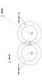
- the control device 100 holds the position information of the dead zone. As shown in FIG. 7, for example, when a dead zone is a circle with a radius R, the control device 100 desensitizes a dead zone for the dead zone from a circle having a radius R + r centered on the center of the dead zone. It is set as a donut-shaped area excluding the zone (circle with radius R). That is, the dead zone is an area centered on the center of the dead zone and having a radius R or more and r or less. “R” may be predetermined or may be dynamically determined according to the speed of the UE 10 or the like.
- the control device 100 compares the current position of the UE 10 acquired in S101 with the dead zone for the dead zone in the base station to which the UE 10 is connected, and the position of the UE 10 is in the dead zone. Whether or not (that is, whether or not the UE 10 has entered the dead zone) is determined. If it is determined that the UE 10 has entered the dead reserve area, the process proceeds to S103. In the above comparison, the control device 100 also compares the current position of the UE 10 acquired in S101 with the dead zone for the dead zone in each base station around the base station to which the UE 10 is connected. ..
- the control device 100 transmits a line switching instruction to the UE 10 (or the connection base station of the UE 10). As described above, a redundant line connection may be instructed.
- the connection destination base station for line switching (or redundant configuration) is a base station in the vicinity where the UE 10 is not located in the dead reserve area.
- the control device 100 determines that the position of the UE 10 is within the dead zone of all the surrounding base stations (all the peripheral base stations to which the UE 10 can be connected), the connected base station and all the peripheral bases concerned. Among the stations, the base station having the largest distance from the center of the dead zone corresponding to the dead zone in which the UE 10 is located is selected, and that base station is used as the connection destination of the UE 10.
- the base station selection as described above is performed. ing.
- the control is performed.
- the device 100 connects the UE 10 to the base station 2 having a large distance from the center.
- the control device 100 performs the dead zone calculation process, which is an example.
- a device other than the control device 100 may perform a dead zone calculation process, and the control device 100 may receive information on the dead zone from the device.
- a plurality of sensors 50 are arranged in the service providing area.
- the service providing area is a service providing area of the base station.
- FIG. 9 shows the service providing area of the base station 60 as an example.
- Each sensor 50 has a function of measuring reception quality and feeding back the measurement result to the control device 100.
- Each UE (UEs 10A and 10B are shown in FIG. 9) also has a function of measuring the reception quality and feeding back the measurement result to the control device 100.
- the sensor 50 and the base station 60 may be wirelessly connected or may be wiredly connected.
- each sensor 50 has a communication function with the base station similar to the UE 10, and uses a user data area or a control message by allocation from the base station 60.
- the feedback signal can be transmitted to the base station 60.
- each sensor 50 measures the reception quality (received radio wave information) and transmits it to the control device 100.
- Each UE 10 transmits its own position information and reception quality to the control device 100.
- the reception quality is, for example, one of SS-RSRP, CSI-RSRP, NR-RSSI, CSI-RSSI, SS-RSRQ, CSI-RSRQ, SS-SINR, CSI-SINR, or a combination of any one or more.
- uplink communication of the target wireless system may be used, or another access means such as a wired connection or a wireless LAN may be used.
- control device 100 grasps the position where the dead zone is detected based on the received reception quality and the position information associated with the sensor 50 of the transmission source of the reception quality.
- the control device 100 determines that the received radio wave condition at that position is good, and the reception quality is a predetermined threshold value. If it is not the above, it is determined that the received radio wave condition at that position is defective (Bad).
- the control device 100 determines that the position determined that the received radio wave condition is bad (Bad) is the position of the dead zone.
- the position is assumed to be a two-dimensional position such as xy coordinates, longitude, and latitude, but when targeting indoor facilities, etc., the height direction (z-axis direction) is added.
- the three-dimensional position may be targeted.
- the dead zone has a three-dimensional shape (for example, a sphere).
- the control device 100 determines the range of the radius R as the dead zone centering on the position where the dead zone is detected, and stores the information of the dead zone (eg, the radius and the center position of the circle) in the DB.
- R is a predetermined value. It should be noted that setting a dead zone in this way is an example.
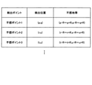
- FIG. 11 shows an example of dead zone information stored in the DB.
- information on the position and the dead zone is stored for each detected dead point.
- (p-R to p + R, q-R to q + R) means a circle having a radius R centered on (p, q).
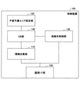
- FIG. 12 is a diagram showing a functional configuration example of the control device 100.
- the control device 100 includes an information collecting unit 110, a dead reserve area setting unit 120, a connection destination control unit 130, a DB unit 140, and a communication I / F unit 150.
- the information collecting unit 110 collects UE information (position, speed, strength of radio waves received from the base station, barometric pressure information, etc.). Further, when the control device 100 calculates the dead zone, the information collecting unit 110 collects the reception quality from the sensor 50 and the UE 10 and calculates the dead zone. Further, when the control device 100 does not calculate the dead zone, the information collecting unit 110 receives the calculated dead zone information from another device.
- UE information position, speed, strength of radio waves received from the base station, barometric pressure information, etc.
- the dead zone setting unit 120 sets a dead zone around each dead zone.
- the setting method is as described above.
- the connection destination control unit 130 determines whether or not the UE 10 has entered the dead reserve area by comparing the position of the UE 10 with the dead reserve area, and if it is determined that the UE 10 has entered, controls the connection destination for the UE 10. ..
- the DB unit 140 has a DB (example: FIG. 11) for storing the information collected by the information collecting unit 110 and the calculated information.
- the communication I / F unit 150 transmits / receives data.
- the dead reserve area setting unit 120 calculates the dead reserve area for the base station to which the UE 10 is connected and each peripheral base station to which the UE 10 can be connected.
- the calculated information on the dead reserve area is stored in the DB unit 140.
- the information collecting unit 110 collects UE information (position, speed, radio wave strength from the base station, barometric pressure information, etc.) from the UE 10.
- the collected information is stored in the DB unit 140.
- connection destination control unit 130 reads the position information of the UE 10 and the information of the dead reserve area from the DB unit 140, and the UE 10 determines whether or not the UE 10 is located in the dead reserve area of the connection base station. ..
- connection destination control unit 130 transmits an instruction to the UE 10 (or the connection destination base station) to switch (or make a redundant configuration) the connection line of the UE 10. do. If the determination result of S303 is No, the process returns to S301.
- control device 100 determines the entry into the dead reserve area of the UE 10 and gives a line switching instruction, but this is an example.
- the UE 10 may determine the entry into the dead reserve area and switch the line.
- a UE that makes a deadline reserve area entry determination and switches lines may be called a "control device".
- FIG. 14 shows an example of the configuration of the UE 10 when the UE 10 determines the entry into the dead reserve area and switches the line.
- the configuration of the UE 10 is the same as the configuration of the control device 100. That is, as shown in FIG. 14, the UE 10 has an information collecting unit 11, a dead reserve area setting unit 12, a connection destination control unit 13, a DB unit 14, and a communication I / F unit 15.
- the functions of each unit are the same as those of the corresponding functional unit in the control device 100, and are as follows.
- the information collecting unit 11 includes, for example, a position sensor such as GPS, a speed sensor, an acceleration sensor, and the like, and collects UE information (position, speed, radio wave intensity from a base station, pressure information, etc.) of the UE 10. Further, when the UE 10 calculates a dead zone, the information collecting unit 11 collects reception quality from the sensor 50 and another UE 10 and calculates the dead zone. Further, when the UE 10 does not calculate the dead zone, the information collecting unit 11 receives the calculated dead zone information from another device.
- a position sensor such as GPS, a speed sensor, an acceleration sensor, and the like
- UE information position, speed, radio wave intensity from a base station, pressure information, etc.
- the dead zone setting unit 12 sets a dead zone around each dead zone.
- the setting method is as described above.
- the connection destination control unit 13 determines whether or not the UE 10 has entered the dead reserve area by comparing the position of the UE 10 with the dead reserve area, and if it is determined that the UE 10 has entered, controls the connection destination of the UE 10. .. For example, the connection destination base station of the UE 10 is switched from the connection destination base station to another base station. Further, the connection destination control unit 13 may instruct the connection base station or the wireless LAN-AP to switch the connection.
- the DB unit 14 has a DB (example: FIG. 11) for storing information collected or calculated by the information collecting unit 11.
- the communication I / F unit 15 transmits / receives data.
- the operation of the UE 10 in the modification 10 is the same as the operation of the control device 100 shown in FIG.
- Each of the control device 100 and the UE 10 in the present embodiment can be realized by, for example, causing a computer to execute a program describing the processing contents described in the present embodiment.
- the "computer” used as the control device 100 may be a physical machine or a virtual machine on the cloud.
- the "hardware” described here is virtual hardware.
- the above program can be recorded on a computer-readable recording medium (portable memory, etc.), saved, and distributed. It is also possible to provide the above program through a network such as the Internet or e-mail.
- FIG. 15 is a diagram showing an example of the hardware configuration of the computer.
- the computer of FIG. 15 has a drive device 1000, an auxiliary storage device 1002, a memory device 1003, a CPU 1004, an interface device 1005, a display device 1006, an input device 1007, an output device 1008, and the like, which are connected to each other by a bus BS, respectively.
- the program that realizes the processing on the computer is provided by, for example, a recording medium 1001 such as a CD-ROM or a memory card.
- a recording medium 1001 such as a CD-ROM or a memory card.
- the program is installed in the auxiliary storage device 1002 from the recording medium 1001 via the drive device 1000.
- the program does not necessarily have to be installed from the recording medium 1001, and may be downloaded from another computer via the network.
- the auxiliary storage device 1002 stores the installed program and also stores necessary files, data, and the like.
- the memory device 1003 reads and stores the program from the auxiliary storage device 1002 when the program is instructed to start.
- the CPU 1004 realizes the function related to the control device 100 or the UE 10 according to the program stored in the memory device 1003.
- the interface device 1005 is used as an interface for connecting to a network, and functions as a transmitting unit and a receiving unit.
- the display device 1006 displays a GUI (Graphical User Interface) or the like by a program.
- the input device 1007 is composed of a keyboard, a mouse, buttons, a touch panel, and the like, and is used for inputting various operation instructions.
- the output device 1008 outputs the calculation result.
- a communication system having a terminal that communicates with a base station wirelessly and a control device.
- the terminal includes a transmission unit that transmits the position information of the terminal.
- the control device is The dead zone setting section that sets the area around the dead zone as the dead zone, and the dead zone setting section.
- An information gathering unit that acquires the location information of the terminal, By comparing the position information of the terminal with the dead reserve area, it is determined whether or not the terminal exists in the dead reserve area, and when it is determined that the terminal exists in the dead reserve area, the said.
- a communication system including a connection destination control unit that executes control for switching the connection destination of a terminal.
- the connection destination control unit When the terminal exists in a plurality of dead zones, the connection destination control unit connects the terminal to the base station having the longest distance from the dead zone among the base stations corresponding to the plurality of dead zones.
- the terminal transmits the position information of the terminal
- the control device Set the area around the dead zone as a dead zone, and set it as a dead zone. Acquire the location information of the terminal and By comparing the position information of the terminal with the dead reserve area, it is determined whether or not the terminal exists in the dead reserve area, and when it is determined that the terminal exists in the dead reserve area, the said.
- Connection destination control method that executes control to switch the connection destination of the terminal.
- the control device in a communication system having a terminal that wirelessly communicates with a base station and a control device.
- the dead zone setting section that sets the area around the dead zone as the dead zone, and the dead zone setting section.
- An information gathering unit that acquires the location information of the terminal, By comparing the position information of the terminal with the dead reserve area, it is determined whether or not the terminal exists in the dead reserve area, and when it is determined that the terminal exists in the dead reserve area, the said.
- a control device equipped with a connection destination control unit that executes control to switch the connection destination of the terminal. (Section 6) When the terminal exists in a plurality of dead zones, the connection destination control unit connects the terminal to the base station having the longest distance from the dead zone among the base stations corresponding to the plurality of dead zones. The control device according to paragraph 5 to be selected as.
Landscapes
- Engineering & Computer Science (AREA)
- Computer Networks & Wireless Communication (AREA)
- Signal Processing (AREA)
- Mobile Radio Communication Systems (AREA)
Abstract
Priority Applications (3)
| Application Number | Priority Date | Filing Date | Title |
|---|---|---|---|
| US18/016,248 US12587930B2 (en) | 2020-07-27 | 2020-07-27 | Communication system, connection destination control method, control apparatus and program |
| PCT/JP2020/028756 WO2022024196A1 (fr) | 2020-07-27 | 2020-07-27 | Système de communication, procédé de commande de destination de connexion, dispositif de commande, et programme |
| JP2022539815A JP7428255B2 (ja) | 2020-07-27 | 2020-07-27 | 通信システム、接続先制御方法、制御装置、及びプログラム |
Applications Claiming Priority (1)
| Application Number | Priority Date | Filing Date | Title |
|---|---|---|---|
| PCT/JP2020/028756 WO2022024196A1 (fr) | 2020-07-27 | 2020-07-27 | Système de communication, procédé de commande de destination de connexion, dispositif de commande, et programme |
Publications (1)
| Publication Number | Publication Date |
|---|---|
| WO2022024196A1 true WO2022024196A1 (fr) | 2022-02-03 |
Family
ID=80037861
Family Applications (1)
| Application Number | Title | Priority Date | Filing Date |
|---|---|---|---|
| PCT/JP2020/028756 Ceased WO2022024196A1 (fr) | 2020-07-27 | 2020-07-27 | Système de communication, procédé de commande de destination de connexion, dispositif de commande, et programme |
Country Status (3)
| Country | Link |
|---|---|
| US (1) | US12587930B2 (fr) |
| JP (1) | JP7428255B2 (fr) |
| WO (1) | WO2022024196A1 (fr) |
Cited By (5)
| Publication number | Priority date | Publication date | Assignee | Title |
|---|---|---|---|---|
| WO2024136945A1 (fr) * | 2022-12-20 | 2024-06-27 | Intergraph Corporation | Génération et utilisation de cartes de couverture sans fil |
| US12408003B2 (en) | 2022-12-20 | 2025-09-02 | Intergraph Corporation | Synchronization/resynchronization of data assets based on entering a wireless dead zone geofence |
| US12425894B2 (en) | 2022-12-20 | 2025-09-23 | Intergraph Corporation | Predicting future wireless coverage based on weather |
| US12501278B2 (en) | 2022-12-20 | 2025-12-16 | Intergraph Corporation | Generating wireless coverage maps |
| US12538150B2 (en) | 2022-12-20 | 2026-01-27 | Intergraph Corporation | Synchronization/resynchronization of data assets based on wireless dead zone geofence changes |
Citations (1)
| Publication number | Priority date | Publication date | Assignee | Title |
|---|---|---|---|---|
| JP2019022089A (ja) * | 2017-07-18 | 2019-02-07 | パナソニック株式会社 | 通信装置、通信システム、接続先制御方法、および伝送レート制御方法 |
Family Cites Families (27)
| Publication number | Priority date | Publication date | Assignee | Title |
|---|---|---|---|---|
| US5805999A (en) * | 1995-02-15 | 1998-09-08 | Nec Corporation | Cordless phone system and a method for estimating location of a cordless phone in said cordless phone system |
| US6132306A (en) * | 1995-09-06 | 2000-10-17 | Cisco Systems, Inc. | Cellular communication system with dedicated repeater channels |
| US5852770A (en) * | 1995-09-19 | 1998-12-22 | Sanyo Electric Co., Ltd. | Transmission power control device for a portable terminal |
| US6493561B1 (en) * | 1996-06-24 | 2002-12-10 | Fujitsu Limited | Mobile communication system enabling efficient use of small-zone base stations |
| US9134398B2 (en) * | 1996-09-09 | 2015-09-15 | Tracbeam Llc | Wireless location using network centric location estimators |
| US6650896B1 (en) * | 1998-08-13 | 2003-11-18 | International Business Machines Corporation | Error correlation for wireless networks |
| US6597906B1 (en) * | 1999-01-29 | 2003-07-22 | International Business Machines Corporation | Mobile client-based station communication based on relative geographical position information |
| US6721572B1 (en) * | 2000-03-24 | 2004-04-13 | International Business Machines Corporation | Mobile communication optimization near wireless dead zone regions |
| US6681112B1 (en) * | 2002-04-29 | 2004-01-20 | Nokia Corporation | Handovers of user equipment connections in wireless communications systems |
| US20080108330A1 (en) * | 2006-11-07 | 2008-05-08 | O'neil Douglas | Methods, systems and computer products for notification to a remote party of mobile party presence status change |
| US8195122B1 (en) * | 2007-12-14 | 2012-06-05 | Dp Technologies, Inc. | Method and apparatus for adjusting the frequency of testing for a wireless communications signal |
| JP4897716B2 (ja) | 2008-01-29 | 2012-03-14 | 日本電信電話株式会社 | 無線通信システム、運用管理サーバ装置および無線基地局制御方法 |
| US11323949B2 (en) * | 2008-10-02 | 2022-05-03 | Deadzone Us, Llc | Dead zone in small cell application |
| US20210068034A1 (en) * | 2008-10-02 | 2021-03-04 | Paul R. Juhasz | System for detecting presence of firearm on a premises |
| US8995988B2 (en) * | 2010-07-21 | 2015-03-31 | Softbank Bb Corp. | Communication characteristic analyzing system, communication characteristic analyzing method, and communication characteristic analyzing program |
| JP2013038583A (ja) * | 2011-08-08 | 2013-02-21 | Nec Corp | 無線ネットワークシステム、ネットワーク管理装置及び劣化検出方法 |
| US9020536B1 (en) * | 2012-10-30 | 2015-04-28 | Onasset Intelligence, Inc. | Method and apparatus for tracking a transported item while accommodating communication gaps |
| US10154443B2 (en) * | 2013-06-03 | 2018-12-11 | Avago Technologies International Sales Pte. Limited | Cross radio access technology handoff using caching |
| US9100838B2 (en) * | 2013-07-29 | 2015-08-04 | Electro-Motive Diesel, Inc. | Rail system having a wired communication zone |
| US9264934B2 (en) * | 2013-08-15 | 2016-02-16 | Telefonaktiebolaget L M Ericsson (Publ) | Method and apparatus for controlling the transmission of streaming content in a wireless communication network |
| JP6444263B2 (ja) * | 2015-05-27 | 2018-12-26 | クラリオン株式会社 | コンテンツ配信システム、コンテンツ配信方法 |
| US10812990B2 (en) * | 2017-01-23 | 2020-10-20 | Cable Television Laboratories, Inc. | Client steering |
| US10645588B2 (en) * | 2016-03-22 | 2020-05-05 | Cable Laboratories, Inc | Systems and methods for coordinated access point channel assignment |
| IL255671B (en) * | 2017-11-14 | 2021-09-30 | Everysight Ltd | System and method for determining an image position using one or more anchors |
| US20190373419A1 (en) * | 2018-05-30 | 2019-12-05 | Peloton Technology, Inc. | Voice communications for platooning vehicles |
| WO2020113062A1 (fr) * | 2018-11-28 | 2020-06-04 | Feng Xue | Communication de véhicule aérien sans pilote |
| US11182770B1 (en) * | 2018-12-12 | 2021-11-23 | Square, Inc. | Systems and methods for sensing locations of near field communication devices |
-
2020
- 2020-07-27 WO PCT/JP2020/028756 patent/WO2022024196A1/fr not_active Ceased
- 2020-07-27 JP JP2022539815A patent/JP7428255B2/ja active Active
- 2020-07-27 US US18/016,248 patent/US12587930B2/en active Active
Patent Citations (1)
| Publication number | Priority date | Publication date | Assignee | Title |
|---|---|---|---|---|
| JP2019022089A (ja) * | 2017-07-18 | 2019-02-07 | パナソニック株式会社 | 通信装置、通信システム、接続先制御方法、および伝送レート制御方法 |
Cited By (5)
| Publication number | Priority date | Publication date | Assignee | Title |
|---|---|---|---|---|
| WO2024136945A1 (fr) * | 2022-12-20 | 2024-06-27 | Intergraph Corporation | Génération et utilisation de cartes de couverture sans fil |
| US12408003B2 (en) | 2022-12-20 | 2025-09-02 | Intergraph Corporation | Synchronization/resynchronization of data assets based on entering a wireless dead zone geofence |
| US12425894B2 (en) | 2022-12-20 | 2025-09-23 | Intergraph Corporation | Predicting future wireless coverage based on weather |
| US12501278B2 (en) | 2022-12-20 | 2025-12-16 | Intergraph Corporation | Generating wireless coverage maps |
| US12538150B2 (en) | 2022-12-20 | 2026-01-27 | Intergraph Corporation | Synchronization/resynchronization of data assets based on wireless dead zone geofence changes |
Also Published As
| Publication number | Publication date |
|---|---|
| US20230276335A1 (en) | 2023-08-31 |
| JP7428255B2 (ja) | 2024-02-06 |
| US12587930B2 (en) | 2026-03-24 |
| JPWO2022024196A1 (fr) | 2022-02-03 |
Similar Documents
| Publication | Publication Date | Title |
|---|---|---|
| WO2022024196A1 (fr) | Système de communication, procédé de commande de destination de connexion, dispositif de commande, et programme | |
| CN110958630B (zh) | 一种测量方法及设备 | |
| US11190950B2 (en) | Communication system, communication management method, and network management apparatus | |
| WO2022024197A1 (fr) | Système de communication, procédé de commande de destination de connexion, dispositif de commande, et programme | |
| CN109541655B (zh) | 一种差分定位系统、方法 | |
| US20100167728A1 (en) | Apparatus and method for femto cell coverage mapping using macro base station | |
| CN107371233B (zh) | 同步信号收发方法及无线通信装置 | |
| JP2002320258A (ja) | 無線通信システム | |
| US20190021036A1 (en) | Terminal apparatus, communication system, and connection-destination selection method | |
| US20250247834A1 (en) | Location-matrix based user equipment band scanning | |
| WO2015057767A1 (fr) | Sélection d'un point d'accès afin de déterminer une position d'un dispositif mobile sur la base d'informations de charge de trafic liées au point d'accès | |
| US20220330134A1 (en) | Communication device, communication method, and communication system | |
| KR101639204B1 (ko) | 컴퓨팅 장치의 글로벌 위치를 결정하기 위해 측지 삼각 측량을 사용하고 용이하게 하기 위한 메커니즘 | |
| US20240380534A1 (en) | Base station, wireless communication method, and wireless communication system | |
| WO2022024198A1 (fr) | Système de communication, procédé de commande de destination de connexion, dispositif de commande, et programme | |
| JP5268836B2 (ja) | 移動通信システムおよび移動通信システムにおける移動機の位置標定方法ならびに移動機情報表示方法。 | |
| JP2014052208A (ja) | 位置推定装置、位置推定システム、および、位置推定方法 | |
| KR20130123087A (ko) | 단말 위치 추적 방법 및 장치 | |
| CN111246373A (zh) | 一种通信距离计算方法及装置 | |
| JP7725867B2 (ja) | 通信装置、通信システム、通信方法、および通信用プログラム | |
| JP2013183165A (ja) | 電波環境管理システムおよび電波環境管理方法 | |
| JP2018042078A (ja) | 無線ネットワーク構築支援システム、及び、無線ネットワーク構築支援方法 | |
| JP2007166448A (ja) | 無線通信システム及び基地局切り替え装置 | |
| WO2026047842A1 (fr) | Dispositif de communication, système de communication, procédé de communication et programme | |
| WO2024252524A1 (fr) | Terminal de communication, dispositif de communication et procédé de communication |
Legal Events
| Date | Code | Title | Description |
|---|---|---|---|
| 121 | Ep: the epo has been informed by wipo that ep was designated in this application |
Ref document number: 20947409 Country of ref document: EP Kind code of ref document: A1 |
|
| ENP | Entry into the national phase |
Ref document number: 2022539815 Country of ref document: JP Kind code of ref document: A |
|
| NENP | Non-entry into the national phase |
Ref country code: DE |
|
| 122 | Ep: pct application non-entry in european phase |
Ref document number: 20947409 Country of ref document: EP Kind code of ref document: A1 |
|
| WWG | Wipo information: grant in national office |
Ref document number: 18016248 Country of ref document: US |