WO2022024273A1 - シリーズハイブリッド車両の制御方法及びシリーズハイブリッド車両 - Google Patents
シリーズハイブリッド車両の制御方法及びシリーズハイブリッド車両 Download PDFInfo
- Publication number
- WO2022024273A1 WO2022024273A1 PCT/JP2020/029114 JP2020029114W WO2022024273A1 WO 2022024273 A1 WO2022024273 A1 WO 2022024273A1 JP 2020029114 W JP2020029114 W JP 2020029114W WO 2022024273 A1 WO2022024273 A1 WO 2022024273A1
- Authority
- WO
- WIPO (PCT)
- Prior art keywords
- rotation speed
- engine
- internal combustion
- upper limit
- combustion engine
- Prior art date
- Legal status (The legal status is an assumption and is not a legal conclusion. Google has not performed a legal analysis and makes no representation as to the accuracy of the status listed.)
- Ceased
Links
Images


Classifications
-
- B—PERFORMING OPERATIONS; TRANSPORTING
- B60—VEHICLES IN GENERAL
- B60K—ARRANGEMENT OR MOUNTING OF PROPULSION UNITS OR OF TRANSMISSIONS IN VEHICLES; ARRANGEMENT OR MOUNTING OF PLURAL DIVERSE PRIME-MOVERS IN VEHICLES; AUXILIARY DRIVES FOR VEHICLES; INSTRUMENTATION OR DASHBOARDS FOR VEHICLES; ARRANGEMENTS IN CONNECTION WITH COOLING, AIR INTAKE, GAS EXHAUST OR FUEL SUPPLY OF PROPULSION UNITS IN VEHICLES
- B60K6/00—Arrangement or mounting of plural diverse prime-movers for mutual or common propulsion, e.g. hybrid propulsion systems comprising electric motors and internal combustion engines
- B60K6/20—Arrangement or mounting of plural diverse prime-movers for mutual or common propulsion, e.g. hybrid propulsion systems comprising electric motors and internal combustion engines the prime-movers consisting of electric motors and internal combustion engines, e.g. HEVs
- B60K6/42—Arrangement or mounting of plural diverse prime-movers for mutual or common propulsion, e.g. hybrid propulsion systems comprising electric motors and internal combustion engines the prime-movers consisting of electric motors and internal combustion engines, e.g. HEVs characterised by the architecture of the hybrid electric vehicle
- B60K6/46—Series type
-
- B—PERFORMING OPERATIONS; TRANSPORTING
- B60—VEHICLES IN GENERAL
- B60K—ARRANGEMENT OR MOUNTING OF PROPULSION UNITS OR OF TRANSMISSIONS IN VEHICLES; ARRANGEMENT OR MOUNTING OF PLURAL DIVERSE PRIME-MOVERS IN VEHICLES; AUXILIARY DRIVES FOR VEHICLES; INSTRUMENTATION OR DASHBOARDS FOR VEHICLES; ARRANGEMENTS IN CONNECTION WITH COOLING, AIR INTAKE, GAS EXHAUST OR FUEL SUPPLY OF PROPULSION UNITS IN VEHICLES
- B60K6/00—Arrangement or mounting of plural diverse prime-movers for mutual or common propulsion, e.g. hybrid propulsion systems comprising electric motors and internal combustion engines
- B60K6/20—Arrangement or mounting of plural diverse prime-movers for mutual or common propulsion, e.g. hybrid propulsion systems comprising electric motors and internal combustion engines the prime-movers consisting of electric motors and internal combustion engines, e.g. HEVs
- B60K6/22—Arrangement or mounting of plural diverse prime-movers for mutual or common propulsion, e.g. hybrid propulsion systems comprising electric motors and internal combustion engines the prime-movers consisting of electric motors and internal combustion engines, e.g. HEVs characterised by apparatus, components or means specially adapted for HEVs
- B60K6/40—Arrangement or mounting of plural diverse prime-movers for mutual or common propulsion, e.g. hybrid propulsion systems comprising electric motors and internal combustion engines the prime-movers consisting of electric motors and internal combustion engines, e.g. HEVs characterised by apparatus, components or means specially adapted for HEVs characterised by the assembly or relative disposition of components
-
- B—PERFORMING OPERATIONS; TRANSPORTING
- B60—VEHICLES IN GENERAL
- B60K—ARRANGEMENT OR MOUNTING OF PROPULSION UNITS OR OF TRANSMISSIONS IN VEHICLES; ARRANGEMENT OR MOUNTING OF PLURAL DIVERSE PRIME-MOVERS IN VEHICLES; AUXILIARY DRIVES FOR VEHICLES; INSTRUMENTATION OR DASHBOARDS FOR VEHICLES; ARRANGEMENTS IN CONNECTION WITH COOLING, AIR INTAKE, GAS EXHAUST OR FUEL SUPPLY OF PROPULSION UNITS IN VEHICLES
- B60K6/00—Arrangement or mounting of plural diverse prime-movers for mutual or common propulsion, e.g. hybrid propulsion systems comprising electric motors and internal combustion engines
- B60K6/20—Arrangement or mounting of plural diverse prime-movers for mutual or common propulsion, e.g. hybrid propulsion systems comprising electric motors and internal combustion engines the prime-movers consisting of electric motors and internal combustion engines, e.g. HEVs
- B60K6/22—Arrangement or mounting of plural diverse prime-movers for mutual or common propulsion, e.g. hybrid propulsion systems comprising electric motors and internal combustion engines the prime-movers consisting of electric motors and internal combustion engines, e.g. HEVs characterised by apparatus, components or means specially adapted for HEVs
- B60K6/40—Arrangement or mounting of plural diverse prime-movers for mutual or common propulsion, e.g. hybrid propulsion systems comprising electric motors and internal combustion engines the prime-movers consisting of electric motors and internal combustion engines, e.g. HEVs characterised by apparatus, components or means specially adapted for HEVs characterised by the assembly or relative disposition of components
- B60K6/405—Housings
-
- B—PERFORMING OPERATIONS; TRANSPORTING
- B60—VEHICLES IN GENERAL
- B60W—CONJOINT CONTROL OF VEHICLE SUB-UNITS OF DIFFERENT TYPE OR DIFFERENT FUNCTION; CONTROL SYSTEMS SPECIALLY ADAPTED FOR HYBRID VEHICLES; ROAD VEHICLE DRIVE CONTROL SYSTEMS FOR PURPOSES NOT RELATED TO THE CONTROL OF A PARTICULAR SUB-UNIT
- B60W10/00—Conjoint control of vehicle sub-units of different type or different function
- B60W10/04—Conjoint control of vehicle sub-units of different type or different function including control of propulsion units
- B60W10/06—Conjoint control of vehicle sub-units of different type or different function including control of propulsion units including control of combustion engines
-
- B—PERFORMING OPERATIONS; TRANSPORTING
- B60—VEHICLES IN GENERAL
- B60W—CONJOINT CONTROL OF VEHICLE SUB-UNITS OF DIFFERENT TYPE OR DIFFERENT FUNCTION; CONTROL SYSTEMS SPECIALLY ADAPTED FOR HYBRID VEHICLES; ROAD VEHICLE DRIVE CONTROL SYSTEMS FOR PURPOSES NOT RELATED TO THE CONTROL OF A PARTICULAR SUB-UNIT
- B60W10/00—Conjoint control of vehicle sub-units of different type or different function
- B60W10/04—Conjoint control of vehicle sub-units of different type or different function including control of propulsion units
- B60W10/08—Conjoint control of vehicle sub-units of different type or different function including control of propulsion units including control of electric propulsion units, e.g. motors or generators
-
- B—PERFORMING OPERATIONS; TRANSPORTING
- B60—VEHICLES IN GENERAL
- B60W—CONJOINT CONTROL OF VEHICLE SUB-UNITS OF DIFFERENT TYPE OR DIFFERENT FUNCTION; CONTROL SYSTEMS SPECIALLY ADAPTED FOR HYBRID VEHICLES; ROAD VEHICLE DRIVE CONTROL SYSTEMS FOR PURPOSES NOT RELATED TO THE CONTROL OF A PARTICULAR SUB-UNIT
- B60W10/00—Conjoint control of vehicle sub-units of different type or different function
- B60W10/18—Conjoint control of vehicle sub-units of different type or different function including control of braking systems
-
- B—PERFORMING OPERATIONS; TRANSPORTING
- B60—VEHICLES IN GENERAL
- B60W—CONJOINT CONTROL OF VEHICLE SUB-UNITS OF DIFFERENT TYPE OR DIFFERENT FUNCTION; CONTROL SYSTEMS SPECIALLY ADAPTED FOR HYBRID VEHICLES; ROAD VEHICLE DRIVE CONTROL SYSTEMS FOR PURPOSES NOT RELATED TO THE CONTROL OF A PARTICULAR SUB-UNIT
- B60W10/00—Conjoint control of vehicle sub-units of different type or different function
- B60W10/18—Conjoint control of vehicle sub-units of different type or different function including control of braking systems
- B60W10/184—Conjoint control of vehicle sub-units of different type or different function including control of braking systems with wheel brakes
-
- B—PERFORMING OPERATIONS; TRANSPORTING
- B60—VEHICLES IN GENERAL
- B60W—CONJOINT CONTROL OF VEHICLE SUB-UNITS OF DIFFERENT TYPE OR DIFFERENT FUNCTION; CONTROL SYSTEMS SPECIALLY ADAPTED FOR HYBRID VEHICLES; ROAD VEHICLE DRIVE CONTROL SYSTEMS FOR PURPOSES NOT RELATED TO THE CONTROL OF A PARTICULAR SUB-UNIT
- B60W20/00—Control systems specially adapted for hybrid vehicles
- B60W20/10—Controlling the power contribution of each of the prime movers to meet required power demand
- B60W20/11—Controlling the power contribution of each of the prime movers to meet required power demand using model predictive control [MPC] strategies, i.e. control methods based on models predicting performance
-
- B—PERFORMING OPERATIONS; TRANSPORTING
- B60—VEHICLES IN GENERAL
- B60W—CONJOINT CONTROL OF VEHICLE SUB-UNITS OF DIFFERENT TYPE OR DIFFERENT FUNCTION; CONTROL SYSTEMS SPECIALLY ADAPTED FOR HYBRID VEHICLES; ROAD VEHICLE DRIVE CONTROL SYSTEMS FOR PURPOSES NOT RELATED TO THE CONTROL OF A PARTICULAR SUB-UNIT
- B60W20/00—Control systems specially adapted for hybrid vehicles
- B60W20/10—Controlling the power contribution of each of the prime movers to meet required power demand
- B60W20/13—Controlling the power contribution of each of the prime movers to meet required power demand in order to stay within battery power input or output limits; in order to prevent overcharging or battery depletion
- B60W20/14—Controlling the power contribution of each of the prime movers to meet required power demand in order to stay within battery power input or output limits; in order to prevent overcharging or battery depletion in conjunction with braking regeneration
-
- B—PERFORMING OPERATIONS; TRANSPORTING
- B60—VEHICLES IN GENERAL
- B60W—CONJOINT CONTROL OF VEHICLE SUB-UNITS OF DIFFERENT TYPE OR DIFFERENT FUNCTION; CONTROL SYSTEMS SPECIALLY ADAPTED FOR HYBRID VEHICLES; ROAD VEHICLE DRIVE CONTROL SYSTEMS FOR PURPOSES NOT RELATED TO THE CONTROL OF A PARTICULAR SUB-UNIT
- B60W20/00—Control systems specially adapted for hybrid vehicles
- B60W20/10—Controlling the power contribution of each of the prime movers to meet required power demand
- B60W20/15—Control strategies specially adapted for achieving a particular effect
- B60W20/17—Control strategies specially adapted for achieving a particular effect for noise reduction
-
- B—PERFORMING OPERATIONS; TRANSPORTING
- B60—VEHICLES IN GENERAL
- B60W—CONJOINT CONTROL OF VEHICLE SUB-UNITS OF DIFFERENT TYPE OR DIFFERENT FUNCTION; CONTROL SYSTEMS SPECIALLY ADAPTED FOR HYBRID VEHICLES; ROAD VEHICLE DRIVE CONTROL SYSTEMS FOR PURPOSES NOT RELATED TO THE CONTROL OF A PARTICULAR SUB-UNIT
- B60W30/00—Purposes of road vehicle drive control systems not related to the control of a particular sub-unit, e.g. of systems using conjoint control of vehicle sub-units
- B60W30/18—Propelling the vehicle
- B60W30/18009—Propelling the vehicle related to particular drive situations
- B60W30/18109—Braking
- B60W30/18127—Regenerative braking
-
- B—PERFORMING OPERATIONS; TRANSPORTING
- B60—VEHICLES IN GENERAL
- B60W—CONJOINT CONTROL OF VEHICLE SUB-UNITS OF DIFFERENT TYPE OR DIFFERENT FUNCTION; CONTROL SYSTEMS SPECIALLY ADAPTED FOR HYBRID VEHICLES; ROAD VEHICLE DRIVE CONTROL SYSTEMS FOR PURPOSES NOT RELATED TO THE CONTROL OF A PARTICULAR SUB-UNIT
- B60W30/00—Purposes of road vehicle drive control systems not related to the control of a particular sub-unit, e.g. of systems using conjoint control of vehicle sub-units
- B60W30/18—Propelling the vehicle
- B60W30/188—Controlling power parameters of the driveline, e.g. determining the required power
- B60W30/1882—Controlling power parameters of the driveline, e.g. determining the required power characterised by the working point of the engine, e.g. by using engine output chart
-
- B—PERFORMING OPERATIONS; TRANSPORTING
- B60—VEHICLES IN GENERAL
- B60W—CONJOINT CONTROL OF VEHICLE SUB-UNITS OF DIFFERENT TYPE OR DIFFERENT FUNCTION; CONTROL SYSTEMS SPECIALLY ADAPTED FOR HYBRID VEHICLES; ROAD VEHICLE DRIVE CONTROL SYSTEMS FOR PURPOSES NOT RELATED TO THE CONTROL OF A PARTICULAR SUB-UNIT
- B60W40/00—Estimation or calculation of non-directly measurable driving parameters for road vehicle drive control systems not related to the control of a particular sub unit, e.g. by using mathematical models
- B60W40/12—Estimation or calculation of non-directly measurable driving parameters for road vehicle drive control systems not related to the control of a particular sub unit, e.g. by using mathematical models related to parameters of the vehicle itself, e.g. tyre models
-
- B—PERFORMING OPERATIONS; TRANSPORTING
- B60—VEHICLES IN GENERAL
- B60W—CONJOINT CONTROL OF VEHICLE SUB-UNITS OF DIFFERENT TYPE OR DIFFERENT FUNCTION; CONTROL SYSTEMS SPECIALLY ADAPTED FOR HYBRID VEHICLES; ROAD VEHICLE DRIVE CONTROL SYSTEMS FOR PURPOSES NOT RELATED TO THE CONTROL OF A PARTICULAR SUB-UNIT
- B60W30/00—Purposes of road vehicle drive control systems not related to the control of a particular sub-unit, e.g. of systems using conjoint control of vehicle sub-units
- B60W30/18—Propelling the vehicle
- B60W30/20—Reducing vibrations in the driveline
- B60W2030/206—Reducing vibrations in the driveline related or induced by the engine
-
- B—PERFORMING OPERATIONS; TRANSPORTING
- B60—VEHICLES IN GENERAL
- B60W—CONJOINT CONTROL OF VEHICLE SUB-UNITS OF DIFFERENT TYPE OR DIFFERENT FUNCTION; CONTROL SYSTEMS SPECIALLY ADAPTED FOR HYBRID VEHICLES; ROAD VEHICLE DRIVE CONTROL SYSTEMS FOR PURPOSES NOT RELATED TO THE CONTROL OF A PARTICULAR SUB-UNIT
- B60W2510/00—Input parameters relating to a particular sub-units
- B60W2510/06—Combustion engines, Gas turbines
- B60W2510/0638—Engine speed
-
- B—PERFORMING OPERATIONS; TRANSPORTING
- B60—VEHICLES IN GENERAL
- B60W—CONJOINT CONTROL OF VEHICLE SUB-UNITS OF DIFFERENT TYPE OR DIFFERENT FUNCTION; CONTROL SYSTEMS SPECIALLY ADAPTED FOR HYBRID VEHICLES; ROAD VEHICLE DRIVE CONTROL SYSTEMS FOR PURPOSES NOT RELATED TO THE CONTROL OF A PARTICULAR SUB-UNIT
- B60W2510/00—Input parameters relating to a particular sub-units
- B60W2510/06—Combustion engines, Gas turbines
- B60W2510/0676—Engine temperature
-
- B—PERFORMING OPERATIONS; TRANSPORTING
- B60—VEHICLES IN GENERAL
- B60W—CONJOINT CONTROL OF VEHICLE SUB-UNITS OF DIFFERENT TYPE OR DIFFERENT FUNCTION; CONTROL SYSTEMS SPECIALLY ADAPTED FOR HYBRID VEHICLES; ROAD VEHICLE DRIVE CONTROL SYSTEMS FOR PURPOSES NOT RELATED TO THE CONTROL OF A PARTICULAR SUB-UNIT
- B60W2510/00—Input parameters relating to a particular sub-units
- B60W2510/08—Electric propulsion units
- B60W2510/081—Speed
-
- B—PERFORMING OPERATIONS; TRANSPORTING
- B60—VEHICLES IN GENERAL
- B60W—CONJOINT CONTROL OF VEHICLE SUB-UNITS OF DIFFERENT TYPE OR DIFFERENT FUNCTION; CONTROL SYSTEMS SPECIALLY ADAPTED FOR HYBRID VEHICLES; ROAD VEHICLE DRIVE CONTROL SYSTEMS FOR PURPOSES NOT RELATED TO THE CONTROL OF A PARTICULAR SUB-UNIT
- B60W2510/00—Input parameters relating to a particular sub-units
- B60W2510/08—Electric propulsion units
- B60W2510/083—Torque
-
- B—PERFORMING OPERATIONS; TRANSPORTING
- B60—VEHICLES IN GENERAL
- B60W—CONJOINT CONTROL OF VEHICLE SUB-UNITS OF DIFFERENT TYPE OR DIFFERENT FUNCTION; CONTROL SYSTEMS SPECIALLY ADAPTED FOR HYBRID VEHICLES; ROAD VEHICLE DRIVE CONTROL SYSTEMS FOR PURPOSES NOT RELATED TO THE CONTROL OF A PARTICULAR SUB-UNIT
- B60W2520/00—Input parameters relating to overall vehicle dynamics
- B60W2520/10—Longitudinal speed
-
- B—PERFORMING OPERATIONS; TRANSPORTING
- B60—VEHICLES IN GENERAL
- B60W—CONJOINT CONTROL OF VEHICLE SUB-UNITS OF DIFFERENT TYPE OR DIFFERENT FUNCTION; CONTROL SYSTEMS SPECIALLY ADAPTED FOR HYBRID VEHICLES; ROAD VEHICLE DRIVE CONTROL SYSTEMS FOR PURPOSES NOT RELATED TO THE CONTROL OF A PARTICULAR SUB-UNIT
- B60W2530/00—Input parameters relating to vehicle conditions or values, not covered by groups B60W2510/00 or B60W2520/00
- B60W2530/12—Catalyst or filter state
-
- B—PERFORMING OPERATIONS; TRANSPORTING
- B60—VEHICLES IN GENERAL
- B60W—CONJOINT CONTROL OF VEHICLE SUB-UNITS OF DIFFERENT TYPE OR DIFFERENT FUNCTION; CONTROL SYSTEMS SPECIALLY ADAPTED FOR HYBRID VEHICLES; ROAD VEHICLE DRIVE CONTROL SYSTEMS FOR PURPOSES NOT RELATED TO THE CONTROL OF A PARTICULAR SUB-UNIT
- B60W2540/00—Input parameters relating to occupants
- B60W2540/10—Accelerator pedal position
-
- B—PERFORMING OPERATIONS; TRANSPORTING
- B60—VEHICLES IN GENERAL
- B60W—CONJOINT CONTROL OF VEHICLE SUB-UNITS OF DIFFERENT TYPE OR DIFFERENT FUNCTION; CONTROL SYSTEMS SPECIALLY ADAPTED FOR HYBRID VEHICLES; ROAD VEHICLE DRIVE CONTROL SYSTEMS FOR PURPOSES NOT RELATED TO THE CONTROL OF A PARTICULAR SUB-UNIT
- B60W2540/00—Input parameters relating to occupants
- B60W2540/12—Brake pedal position
-
- B—PERFORMING OPERATIONS; TRANSPORTING
- B60—VEHICLES IN GENERAL
- B60W—CONJOINT CONTROL OF VEHICLE SUB-UNITS OF DIFFERENT TYPE OR DIFFERENT FUNCTION; CONTROL SYSTEMS SPECIALLY ADAPTED FOR HYBRID VEHICLES; ROAD VEHICLE DRIVE CONTROL SYSTEMS FOR PURPOSES NOT RELATED TO THE CONTROL OF A PARTICULAR SUB-UNIT
- B60W2710/00—Output or target parameters relating to a particular sub-units
- B60W2710/06—Combustion engines, Gas turbines
- B60W2710/0644—Engine speed
-
- B—PERFORMING OPERATIONS; TRANSPORTING
- B60—VEHICLES IN GENERAL
- B60W—CONJOINT CONTROL OF VEHICLE SUB-UNITS OF DIFFERENT TYPE OR DIFFERENT FUNCTION; CONTROL SYSTEMS SPECIALLY ADAPTED FOR HYBRID VEHICLES; ROAD VEHICLE DRIVE CONTROL SYSTEMS FOR PURPOSES NOT RELATED TO THE CONTROL OF A PARTICULAR SUB-UNIT
- B60W2710/00—Output or target parameters relating to a particular sub-units
- B60W2710/06—Combustion engines, Gas turbines
- B60W2710/0666—Engine torque
-
- B—PERFORMING OPERATIONS; TRANSPORTING
- B60—VEHICLES IN GENERAL
- B60W—CONJOINT CONTROL OF VEHICLE SUB-UNITS OF DIFFERENT TYPE OR DIFFERENT FUNCTION; CONTROL SYSTEMS SPECIALLY ADAPTED FOR HYBRID VEHICLES; ROAD VEHICLE DRIVE CONTROL SYSTEMS FOR PURPOSES NOT RELATED TO THE CONTROL OF A PARTICULAR SUB-UNIT
- B60W2710/00—Output or target parameters relating to a particular sub-units
- B60W2710/08—Electric propulsion units
- B60W2710/081—Speed
-
- B—PERFORMING OPERATIONS; TRANSPORTING
- B60—VEHICLES IN GENERAL
- B60W—CONJOINT CONTROL OF VEHICLE SUB-UNITS OF DIFFERENT TYPE OR DIFFERENT FUNCTION; CONTROL SYSTEMS SPECIALLY ADAPTED FOR HYBRID VEHICLES; ROAD VEHICLE DRIVE CONTROL SYSTEMS FOR PURPOSES NOT RELATED TO THE CONTROL OF A PARTICULAR SUB-UNIT
- B60W2710/00—Output or target parameters relating to a particular sub-units
- B60W2710/08—Electric propulsion units
- B60W2710/083—Torque
-
- B—PERFORMING OPERATIONS; TRANSPORTING
- B60—VEHICLES IN GENERAL
- B60W—CONJOINT CONTROL OF VEHICLE SUB-UNITS OF DIFFERENT TYPE OR DIFFERENT FUNCTION; CONTROL SYSTEMS SPECIALLY ADAPTED FOR HYBRID VEHICLES; ROAD VEHICLE DRIVE CONTROL SYSTEMS FOR PURPOSES NOT RELATED TO THE CONTROL OF A PARTICULAR SUB-UNIT
- B60W2710/00—Output or target parameters relating to a particular sub-units
- B60W2710/18—Braking system
- B60W2710/182—Brake pressure, e.g. of fluid or between pad and disc
-
- Y—GENERAL TAGGING OF NEW TECHNOLOGICAL DEVELOPMENTS; GENERAL TAGGING OF CROSS-SECTIONAL TECHNOLOGIES SPANNING OVER SEVERAL SECTIONS OF THE IPC; TECHNICAL SUBJECTS COVERED BY FORMER USPC CROSS-REFERENCE ART COLLECTIONS [XRACs] AND DIGESTS
- Y02—TECHNOLOGIES OR APPLICATIONS FOR MITIGATION OR ADAPTATION AGAINST CLIMATE CHANGE
- Y02T—CLIMATE CHANGE MITIGATION TECHNOLOGIES RELATED TO TRANSPORTATION
- Y02T10/00—Road transport of goods or passengers
- Y02T10/60—Other road transportation technologies with climate change mitigation effect
- Y02T10/62—Hybrid vehicles
Definitions
- the present invention relates to a control method for a series hybrid vehicle and a series hybrid vehicle.
- the casing of the drive motor is connected to the internal combustion engine and the internal combustion engine and the drive motor are mounted on the vehicle in an integrated state.
- the engine mount supporting the internal combustion engine is compressed by the reaction force, and the spring constant of the engine mount increases.
- the resonance rotation speed range of the engine rotation speed in which floor vibration becomes a problem, shifts to the high rotation speed side.
- the upper limit of the engine rotation speed is limited to promote warming up of the exhaust purification catalyst and the internal combustion engine operates at a relatively low rotation speed
- the engine rotation speed falls within the above resonance rotation speed range. There is a risk. That is, resonance may occur due to the combustion excitation force of the internal combustion engine, and the floor vibration may increase.
- an object of the present invention is to suppress an increase in floor vibration caused by a shift of the resonance rotation speed range to the high rotation speed side due to the generation of torque by the drive motor.
- a control method for controlling a series hybrid vehicle supported by a vehicle body via a plurality of mount members in a state where a drive motor and an internal combustion engine are integrated wherein the controller is a control method.
- a power generation motor driven by the power of an internal combustion engine is made to generate power, and the generated power is used to drive the drive motor to drive the drive wheels.
- the drive motor generates regenerative torque according to the deceleration request.
- the upper limit of the regenerative torque is set from the floor vibration generation region in which the engine rotation speed of the internal combustion engine at the time of power generation is the engine rotation speed region in which resonance occurs on the floor of the vehicle body and is determined based on the upper limit of the regenerative torque.
- the regenerative torque is generated by the drive motor, limited to a higher size.
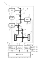
- FIG. 1 is a schematic configuration diagram showing a main part of a vehicle.
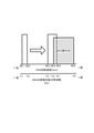
- FIG. 2 is a diagram for explaining a mechanism by which floor vibration increases.
- FIG. 3 is a timing chart when the lower limit of the engine operating point region is limited during cooperative regenerative braking.
- FIG. 4 is a block diagram showing a processing function for executing cooperative regenerative braking.
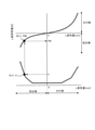
- FIG. 5 is a diagram for explaining a method of calculating the upper limit value of the regenerative torque.
- FIG. 6 is an example of a table used for calculating the lower limit rotation speed.
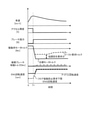
- FIG. 7 is an example of a timing chart when the control according to the present embodiment is executed.
- FIG. 8 is a timing chart when the control according to the modified example of the present embodiment is executed.
- FIG. 1 is a schematic configuration diagram showing a main part of the vehicle 1.
- the vehicle 1 includes an internal combustion engine 2 (ENG in the figure), a power generation motor 3 (GEN in the figure), a drive motor 4 (MG in the figure), a battery 5, and a drive wheel 6.
- the drive wheel 6 is the front wheel of the vehicle 1. That is, the vehicle 1 is a front-wheel drive vehicle.
- the internal combustion engine 2 may be either a gasoline engine or a diesel engine.
- the power generation motor 3 is driven by the power of the internal combustion engine 2 to generate power.
- the drive motor 4 is driven by the electric power of the battery 5 to drive the drive wheels 6.
- the drive motor 4 also has a so-called regenerative function in which deceleration energy is regenerated as electric power by being rotated along with the rotation of the drive wheels 6 during deceleration or the like.
- the battery 5 is charged with the electric power generated by the power generation motor 3 and the electric power regenerated by the drive motor 4.
- the vehicle 1 has a first power transmission path 21 and a second power transmission path 22.
- the first power transmission path 21 transmits power between the drive motor 4 and the drive wheels 6.
- the second power transmission path 22 transmits power between the internal combustion engine 2 and the power generation motor 3.
- the first power transmission path 21 and the second power transmission path 22 are independent power transmission paths, that is, a power transmission path in which power is not transmitted from one of the first power transmission path 21 and the second power transmission path 22 to the other. It has become.
- the first power transmission path 21 is coaxial with the first reduction gear 11 provided on the rotary shaft 4a of the drive motor 4, the second reduction gear 12 that meshes with the first reduction gear 11, and the second reduction gear 12. It is configured to have a third reduction gear 13 provided and meshing with the differential gear 14, and a differential gear 14 provided in the differential case 15.
- the second power transmission path 22 is provided on the fourth reduction gear 16 provided on the output shaft 2a of the internal combustion engine 2, the fifth reduction gear 17 that meshes with the fourth reduction gear 16, and the rotary shaft 3a of the power generation motor 3. It is configured to have a sixth reduction gear 18 that meshes with the fifth reduction gear 17.
- Each of the first power transmission path 21 and the second power transmission path 22 does not have an element for blocking power transmission. That is, each of the first power transmission path 21 and the second power transmission path 22 is in a state where power is always transmitted.
- the second power transmission path 22 constitutes the power transmission path of the power transmission system 23.
- the power transmission system 23 includes the internal combustion engine 2 and the power generation motor 3, and the power is transmitted from the power generation motor 3 to the internal combustion engine 2 when the internal combustion engine 2 is motorized.
- the vehicle 1 further includes a controller 30 as a control unit.
- the controller 30 integrates the control of the engine controller 31 that controls the internal combustion engine 2, the power generation motor controller 32 that controls the power generation motor 3, the drive motor controller 33 that controls the drive motor 4, and the vehicle 1.
- the skid prevention device 41 and the body control module 42 which will be described later, are included.
- the engine controller 31 is composed of a microcomputer equipped with a central arithmetic unit (CPU), a read-only memory (ROM), a random access memory (RAM), and an input / output interface (I / O interface). The same applies to the power generation motor controller 32, the drive motor controller 33, and the integrated controller 34.
- the engine controller 31, the power generation motor controller 32, and the drive motor controller 33 are communicably connected to each other by a CAN standard bus via the integrated controller 34.
- the controller 30 includes a rotation speed sensor 81 for detecting the rotation speed NE of the internal combustion engine 2, an accelerator opening sensor 82 for detecting an accelerator opening APO that indicates the amount of depression of the accelerator pedal, and a water temperature of the internal combustion engine 2. Signals from various sensors and switches including a water temperature sensor 83 for detecting THW and a vehicle speed sensor 84 for detecting vehicle speed VSP are input. These signals are input to the integrated controller 34 either directly or via another controller such as the engine controller 31.
- the vehicle speed VSS may be directly input to the integrated controller 34 from the vehicle speed sensor 84 via the electronic stability control (VDC) 41.
- the vehicle 1 constitutes a series hybrid vehicle in which the drive wheels 6 are driven by the drive motor 4 by using the electric power of the power generation motor 3 that is driven by the power of the internal combustion engine 2 to generate electric power.
- the internal combustion engine 2 and the drive motor 4 are drawn at separate positions in order to make it easier to understand the power transmission path, but in reality, the casing accommodating the drive motor 4 is used for power. It is connected to and integrated with the internal combustion engine 2 via a gearbox as a transmission path 22.
- the internal combustion engine 2 and the drive motor 4 are elastically supported by the vehicle 1 via the engine mount 7 and the motor mount (not shown) in an integrated state.
- the driver drives the vehicle 1 by switching between a plurality of ranges and drive modes.
- the range is switched by operating a shifter (not shown).
- the range selectable by the shifter includes a parking range (P range), a reverse range (R range), a neutral range (N range), a first forward range (D range) and a second (B range). When it is not necessary to distinguish between the D range and the B range, these may be collectively referred to as a forward range.
- the drive mode can be switched by operating a drive mode switch (not shown).
- the drive mode includes N mode, S mode and ECO mode.
- the N mode is a mode in which acceleration is performed by operating the accelerator pedal (normal regeneration mode). Therefore, in the N mode, regenerative deceleration is not performed while the accelerator pedal is being operated, and regenerative deceleration is performed when the accelerator pedal is off.
- the S mode and the ECO mode are modes in which acceleration and regenerative deceleration are performed by operating the accelerator pedal (one-pedal mode), and the ECO mode is a mode more suitable for fuel-efficient driving than the S mode.
- the D range constitutes an ND mode in combination with N mode, an SD mode in combination with S mode, and an ECO-D mode in combination with ECO mode, depending on the combination with the selected drive mode.
- the B range constitutes an NB mode, an SB mode, and an ECO-B mode in combination with the selected drive mode.
- the B range is a range in which the deceleration of the vehicle 1 caused by the regeneration of the drive motor 4 is larger than that of the D range.
- the target deceleration is set larger in the B range than in the D range.
- a large deceleration means that the degree of deceleration is large (the absolute value of deceleration is large). The same applies to the target deceleration.
- the B range the absolute value of the regenerative power by the drive motor 4 becomes larger than in the D range, and as a result, the deceleration becomes larger.
- the SD mode and the ECO-D mode the regenerative power by the drive motor 4 becomes larger than that in the ND mode, and as a result, the deceleration becomes larger.
- the N mode is also referred to as a normal regeneration mode
- the S mode and the ECO mode are also referred to as a strong regeneration mode.
- coordinated regenerative braking is executed when the vehicle 1 decelerates.
- cooperative regenerative braking is a braking force that is determined by the driver's brake pedal operation amount, etc., a braking force of a friction brake that operates by hydraulic pressure, and a braking force that is generated by the regeneration of a drive motor 4. It is a control obtained by combining with.
- the braking force by the drive motor 4 is used, and when the braking force is insufficient with respect to the target braking force by itself, the friction brake is operated. That is, at the time of coordinated regenerative braking, the regenerative torque of the drive motor 4 is larger than the regenerative torque due to coastal running.
- the engine mount 7 is compressed by the reaction force. Then, as the engine mount 7 is compressed, the spring constant (elastic modulus) of the engine mount 7 becomes large. As a result, the natural frequency of the one-degree-of-freedom system including the internal combustion engine 2 and the engine mount 7 increases. Generally, in order to suppress so-called floor vibration, the natural frequency of the one-degree-of-freedom system including the internal combustion engine 2 and the engine mount 7 is set to be lower than the frequency range of vibration during operation of the internal combustion engine 2. The spring constant of the engine mount 7 is set. However, if the engine mount 7 is compressed by the reaction force of the torque of the drive motor 4 and the natural frequency increases as described above, the natural frequency may enter the frequency range of vibration during the operation of the internal combustion engine 2. FIG. 2 shows this.
- the horizontal axis in FIG. 2 is the engine rotation speed and the frequency of the combustion excitation force of the internal combustion engine.
- Figure 2 is. For example, it indicates that the combustion excitation force when the engine rotation speed is NE1 is F1.
- the rotation speed region from the engine rotation speed NE1 to the engine rotation speed NE2 is a region where resonance occurs due to the combustion excitation force when the drive motor 4 does not generate torque (hereinafter, also referred to as a resonance rotation speed region). be.
- the rotation speed region from the engine rotation speed NE5 to the engine rotation speed NE6 is a region that can be taken when the internal combustion engine 2 operates for power generation (hereinafter, also referred to as an engine operating point region).
- the resonance rotation speed region is far from the engine operating point region as shown in FIG. 2, so that resonance occurs even if the internal combustion engine 2 operates for power generation. No. And since resonance does not occur, floor vibration does not become a problem.
- floor vibration becomes a problem means that the floor vibration exceeds the permissible value.
- the permissible value is arbitrarily set according to the specifications of the vehicle 1 to which the present embodiment is applied.
- the resonance rotation speed range shifts to the high rotation side as described above.
- the resonance rotation speed region shifts to NE3-NE5
- an overlapping portion between the resonance rotation speed region and the engine operating point region occurs. That is, resonance occurs due to the combustion excitation force of the internal combustion engine 2 that operates for power generation, which causes a problem of floor vibration.
- FIG. 3 is a timing chart when the lower limit of the engine operating point region is limited during coordinated regenerative braking.
- the vehicle is running with the accelerator pedal depressed until timing T1, the accelerator pedal is turned off at timing T1, the brake pedal is depressed, and deceleration is started.
- the torque of the drive motor 4 (drive motor torque in the figure) changes from positive to negative, and power generation by regeneration starts.
- the torque at this time (solid line in the figure) is the coast regenerative torque (broken line in the figure) plus the coordinated regenerative torque. If the target braking force according to the brake pedal force cannot be achieved even if the coordinated regenerative torque is applied, the insufficient braking force is covered by the friction brake (dashed line in the figure).
- the lower limit of the engine rotation speed is raised.
- the lower limit of the engine rotation speed is increased in accordance with the decrease (increase in the negative direction) of the drive motor torque.
- the lower limit of the engine operating point region can be made higher than the resonance rotation speed region, so that an increase in floor vibration can be suppressed.
- the upper limit of the engine rotation speed of the internal combustion engine 2 at the time of power generation may be limited.
- the engine rotation speed For example, during the execution of the catalyst warm-up mode for warming up the exhaust gas purification catalyst immediately after the start of the hybrid system, and during the execution of the recover mode for raising the temperature of the exhaust gas purification catalyst whose temperature has dropped during running, the engine rotation speed.
- the upper limit of is limited.
- the amount of heat transfer from the internal combustion engine 2 to peripheral devices may increase. Even during the execution of the thermal protection mode to suppress this, the upper limit of the engine speed is limited.
- both cooperative regenerative braking and suppression of floor vibration are achieved even when the upper limit of the engine rotation speed is limited.
- FIG. 4 is a block diagram showing a processing function for executing cooperative regenerative braking of the controller 30 (specifically, the integrated controller 34).
- the integrated controller 34 includes a motor driving force calculation unit 43, a conversion unit 44, a motor torque command value calculation unit 45, a regenerative torque upper limit value setting unit 46, a regenerative torque upper limit value transmission unit 47, and a lower limit rotation speed calculation. It has a motor torque calculation unit 48, a lower limit rotation speed calculation unit 29, a required rotation speed calculation unit 50, and a required engine torque calculation unit 51. It should be noted that each of these arithmetic units indicates an arithmetic processing function and does not mean a physical configuration.
- the motor driving force calculation unit 43 calculates the required driving force according to the accelerator opening based on the accelerator opening APO, the vehicle speed VSS, and the current drive mode input from the BCM 42.
- the BCM 42 is a controller (body control module) that controls the operation of electrical components.
- For the required driving force for example, a map capable of searching the driving force by the accelerator opening APO and the vehicle speed VSS for each drive mode is created in advance and stored in the integrated controller 34, and the map is searched based on the input signal. Calculate by.
- the conversion unit 44 converts the required driving force into the torque (required torque) of the driving motor 4.
- the required torque obtained here is input to the motor torque command value calculation unit 45 and the lower limit rotation speed calculation motor torque calculation unit 48.
- the regenerative torque upper limit value setting unit 46 sets the regenerative torque upper limit value, which is the upper limit value of the regenerative torque of the drive motor 4 for preventing floor vibration, by the following method.
- the vibration due to the combustion excitation force of the internal combustion engine 2 is treated as a vibration of a one-degree-of-freedom system in which the internal combustion engine 2 is a rigid body having a mass m and the engine mount 7 is an elastic body having a spring constant k.
- the motor mount is treated as a one-degree-of-freedom system only for the engine mount 7 without considering the motor mount that elastically supports the drive motor 4 integrated with the internal combustion engine 2, because the motor mount is located at a position away from the internal combustion engine 2. This is because it is installed and can be ignored when considering the vibration of the internal combustion engine 2.
- the combustion excitation force frequency fe during operation at the upper limit engine rotation speed Ru which is the lowest engine rotation speed
- the internal combustion engine 2 has three cylinders, and the combustion excitation force frequency of the 1.5th-order rotation is calculated.
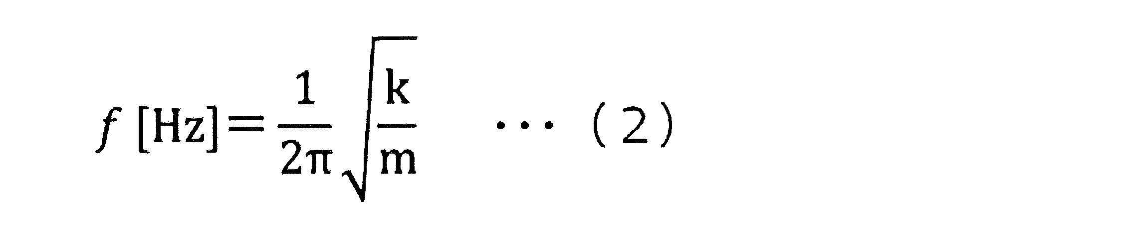
- the natural frequency of the above one-degree-of-freedom system is represented by the equation (2).
- the target natural frequency ft which is the frequency when the floor vibration is at an allowable level, is expressed by the equation (3).
- the ⁇ in the equation (3) is a coefficient for releasing the natural frequency f to the allowable level of the floor vibration. This coefficient ⁇ can be set arbitrarily.
- the regenerative torque upper limit value setting unit 46 calculates the regenerative torque upper limit value. Specifically, it is calculated by the method shown in FIG.
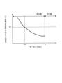
- FIG. 5 shows the spring constant characteristics of the engine mount 7 measured in advance.
- the upper part of FIG. 5 shows the relationship between the load acting on the engine mount 7 and the deformation amount (also referred to as the compression amount) of the engine mount 7, and the lower part of FIG. 5 shows the relationship between the deformation amount of the engine mount 7 and the spring constant. ing.
- the deformation amount x1 when the spring constant k determined by the equation (4) is calculated.
- the regenerative torque upper limit value is obtained by converting the load FM thus obtained into torque.
- the regenerative torque upper limit value set by the regenerative torque upper limit value setting unit 46 is input to the motor torque command value calculation unit 45 and the regenerative torque upper limit value transmission unit 47.
- the regenerative torque upper limit value transmitting unit transmits the regenerative torque upper limit value to the VDC 41.
- the VDC 41 controls the hydraulic pressure of the friction brake so that the braking force corresponding to the difference between the upper limit value of the regenerative torque and the required regenerative torque described later is compensated by the friction brake.
- the motor torque command value calculation unit 45 In addition to the above-mentioned upper limit of regenerative torque and the required torque according to the accelerator opening, the motor torque command value calculation unit 45 also inputs the required regenerative torque according to the brake operation amount from the VDC 41. Then, the motor torque command value calculation unit 45 sets the total regenerative torque determined by the required torque according to the accelerator opening and the required regenerative torque according to the brake operation amount as the motor torque command value, which is limited by the upper limit value of the regenerative torque. It is calculated and input to the drive motor controller 33.
- the required regenerative torque according to the brake operation amount is also input from the VDC 41 to the motor torque calculation unit 48 for calculating the lower limit rotation speed. Then, the motor torque calculation unit 48 for calculating the lower limit rotation speed calculates the lower limit rotation speed of the internal combustion engine 2 by adding the required regeneration torque according to the brake operation amount to the required torque according to the accelerator opening. This is input to the lower limit rotation speed calculation unit 49 as the lower limit rotation speed calculation motor torque.
- the lower limit rotation speed calculation unit 49 calculates the lower limit rotation speed using the motor torque for calculating the lower limit rotation speed. Specifically, it is calculated using a table that specifies the relationship between the motor torque and the lower limit rotation speed, as shown in FIG. 6, for example. For example, when the lower limit rotation speed calculation motor torque is TQ1, the lower limit rotation speed is NE1.
- the required rotation speed calculation unit 50 determines the required rotation speed based on the upper limit rotation speed limited due to the catalyst warm-up mode and the like and the lower limit rotation speed calculated by the lower limit rotation speed calculation unit 49.
- the upper limit rotation speed is prioritized over the lower limit rotation speed. That is, when the upper limit rotation speed is lower than the lower limit rotation speed, the upper limit rotation speed is set as the required rotation speed.
- the required rotation speed is input to the power generation motor controller 32 and the required engine torque calculation unit 51.
- the required engine torque calculation unit 51 calculates the engine torque according to the input required rotation speed, and inputs the calculated engine torque to the engine controller 31.
- the torque of the drive motor 4 and the rotation speed of the internal combustion engine 2 are limited by using the total regenerative torque. Since the vehicle 1 of the present embodiment is a front-wheel drive vehicle, the total regenerative torque is the regenerative torque of the front wheels.
- the total regenerative torque of the front and rear wheels is taken as the total regenerative torque.
- the floor vibration which is a problem in the present embodiment, is generated by the compression of the engine mount 7 due to the motor torque generated by the front wheels and the increase of the natural frequency of the vibration system having the internal combustion engine 2 as a rigid body.
- each of the above restrictions may be applied by the motor torque of the front wheels.
- the torque distribution to the front and rear wheels may change, and if the engine rotation speed changes each time the torque distribution changes, the driver may feel uncomfortable. Therefore, as described above, in the case of a four-wheel drive vehicle, the total regenerative torque of the front and rear wheels is taken as the total regenerative torque.
- the above-mentioned regenerative torque limitation is limited to deceleration when the forward range is selected and the accelerator opening is zero. This is due to the following reasons.
- the forward range is selected and the accelerator pedal is depressed, that is, when there is an acceleration request, the engine rotation speed increases in response to the acceleration request, and the condition that floor vibration increases can be avoided. be.
- the vehicle decelerates when the reverse range is selected and the accelerator opening is zero the required value of the motor torque is small in the first place, so that the condition for increasing the floor vibration is not satisfied.
- the reverse range is selected and the accelerator pedal is depressed, the power performance is prioritized even if the condition for increasing the floor vibration is satisfied.
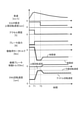
- FIG. 7 is an example of a timing chart when the above control is executed. Here, it is assumed that the upper limit of the engine rotation speed is limited by the thermal protection mode. It is also assumed that the brake pedal is not depressed.
- the required torque of the drive motor 4 decreases as shown by the broken line in the figure (“before the limit” in the figure). In other words, the required regenerative torque increases.
- the engine rotation speed is limited to the upper limit rotation speed lower than the lower limit rotation speed. Therefore, in the present embodiment, the engine rotation speed is limited by the upper limit rotation speed. As a result, the engine rotation speed is as shown by the solid line in the figure.
- the regenerative torque of the drive motor 4 is limited by the regenerative torque upper limit value (dotted line in the figure).
- the regenerative torque is as shown by the solid line in the figure.
- the braking force that decreases due to the limitation of regenerative torque is compensated by the friction brake.
- the present embodiment is a control method for controlling a series hybrid vehicle supported by a vehicle body via a plurality of mount members in a state where the drive motor 4 and the internal combustion engine 2 are integrated, and is a control method 30.
- the power generation motor 3 driven by the power of the internal combustion engine 2 is made to generate power
- the drive motor 4 is made to drive the drive wheel 6 by the generated power
- the drive motor 4 responds to the deceleration request at the time of deceleration.
- a method of controlling a series hybrid vehicle that generates a regenerative torque is provided.
- the upper limit of the regenerative torque is in the engine rotation speed region where resonance occurs on the floor of the vehicle body rather than the engine rotation speed of the internal combustion engine 2 when the power generation motor 3 generates power in a state where the regenerative torque is generated.
- the upper limit of the regenerative torque is limited to a size that lowers the floor vibration generation region determined based on the above, and the regenerative torque is generated by the drive motor 4. In other words, it is an engine rotation speed region where resonance occurs on the floor of the vehicle body rather than the engine rotation speed of the internal combustion engine 2 when the power generation motor 3 generates power in a state where the regeneration torque is generated, and is based on the upper limit of the regeneration torque.
- the upper limit of the regenerative torque is limited so that the floor vibration generation region determined by the engine is lowered, and the regenerative torque is generated by the drive motor 4. This makes it possible to prevent the floor vibration from increasing to an unacceptable magnitude even if the cooperative regenerative braking is executed when the internal combustion engine 2 is operating for power generation.
- the regeneration torque upper limit value setting unit 46 calculates the regeneration torque upper limit value using the lowest engine rotation speed among the upper limit rotation speeds limited in the catalyst warm-up mode, the recover mode, and the thermal protection mode.
- the upper limit of the regenerative torque is calculated using the upper limit rotation speed according to the driving scene. For example, when the upper limit rotation speed differs between the catalyst warm-up mode, the recover mode, and the thermal protection mode, the upper limit rotation speed of the currently executed mode is used. Further, for example, the upper limit rotation speed may change during the execution of the catalyst warm-up mode, in which case the current upper limit rotation speed is used. This makes it possible to prevent the regenerative torque and the engine rotation speed from being limited more than necessary.
- FIG. 8 is an example of a timing chart when the control related to the modification is executed during deceleration during the catalyst warm-up mode.
- the required value of the upper limit rotation speed (EGVR required upper limit rotation speed in the figure) in the catalyst warm-up mode decreases at the timing T2. Further, the upper limit rotation speed is higher than the lower limit rotation speed up to the timing T2, and the upper limit rotation speed corresponding to the EGVR required upper limit rotation speed after the timing T2 is lower than the lower limit rotation speed.
- the engine rotation speed can be increased to the lower limit rotation speed while the upper limit rotation speed is higher than the lower limit rotation speed. I can cover it.
- the engine rotation speed is limited to the upper limit rotation speed lower than the lower limit rotation speed, and as a result, the regenerative torque of the drive motor 4 is also limited.
- the braking force due to the coordinated regeneration becomes insufficient, so that the braking force due to the friction brake is supplemented.
- the lower the upper limit of the engine rotation speed the smaller the upper limit of the regenerative torque of the drive motor 4.
- the lower the upper limit of the engine speed the closer the upper limit of the regenerative torque is to zero.
Landscapes
- Engineering & Computer Science (AREA)
- Transportation (AREA)
- Mechanical Engineering (AREA)
- Chemical & Material Sciences (AREA)
- Combustion & Propulsion (AREA)
- Automation & Control Theory (AREA)
- Physics & Mathematics (AREA)
- Mathematical Physics (AREA)
- Electric Propulsion And Braking For Vehicles (AREA)
- Hybrid Electric Vehicles (AREA)
- Control Of Vehicle Engines Or Engines For Specific Uses (AREA)
Abstract
Description
ここでは、内燃機関2の燃焼加振力による振動を、内燃機関2を質量mの剛体、エンジンマウント7をバネ定数kの弾性体とする1自由度系の振動として扱う。なお、内燃機関2と一体化された駆動用モータ4を弾性支持するモータマウントを考慮せずにエンジンマウント7のみの1自由度系として扱うのは、モータマウントは内燃機関2から離れた位置に設置されているため、内燃機関2の振動を考える際に無視し得るからである。



次に、上記実施形態の変形例について説明する。この変形例も本発明の範囲に属する。
Claims (5)
- 駆動用モータと内燃機関とが一体化された状態で複数のマウント部材を介して車体に支持されるシリーズハイブリッド車両を制御する制御方法であって、
コントローラが、
内燃機関の動力により駆動される発電用モータに発電を行わせ、
発電した電力により駆動用モータをさせて駆動輪を駆動し、
減速時には前記駆動用モータに減速要求に応じた回生トルクを発生させる、シリーズハイブリッド車両の制御方法において、
前記回生トルクが発生している状態で前記発電用モータが発電する際の前記内燃機関のエンジン回転速度よりも、車体フロア部の共振が生じるエンジン回転速度領域であって前記回生トルクの上限に基づいて定まるフロア振動発生領域が低くなる大きさに前記回生トルクの上限を制限して、前記駆動用モータにより前記回生トルクを発生させる、シリーズハイブリッド車両の制御方法。 - 請求項1に記載のシリーズハイブリッド車両の制御方法において、
発電時の前記内燃機関の上限回転速度における燃焼加振力周波数と、前記複数のマウント部材のうちの一つであるエンジンマウントに弾性支持される前記内燃機関の固有周波数とが等しくなる場合の前記エンジンマウントのバネ定数を算出し、
算出された前記バネ定数になるときの前記エンジンマウントの圧縮量を算出し、
当該圧縮量になるときの前記駆動用モータのトルクを、回生トルク上限値とする、シリーズハイブリッド車両の制御方法。 - 請求項2に記載のシリーズハイブリッド車両の制御方法において、
前記上限回転速度が低いほど、前記回生トルク上限値を低くする、シリーズハイブリッド車両の制御方法。 - 請求項2または3に記載のシリーズハイブリッド車両の制御方法において、
前記回生トルクが大きいほど前記エンジンマウントの圧縮量が大きくなり、
前記エンジンマウントの圧縮量が大きいほど、前記フロア振動発生領域が高いエンジン回転速度領域になる、シリーズハイブリッド車両の制御方法。 - 内燃機関と、
前記内燃機関の動力により駆動される発電用モータと、
前記発電用モータが発電した電力により駆動される駆動用モータと、
減速時に前記駆動用モータに減速要求に応じた回生トルクを発生させるよう制御する制御部と、
を備え、
駆動用モータと内燃機関とが一体化された状態で複数のマウント部材を介して車体に支持されるシリーズハイブリッド車両において、
前記制御部は、前記回生トルクが発生している状態で前記発電用モータが発電する際の前記内燃機関のエンジン回転速度よりも、車体フロア部の共振が生じるエンジン回転速度領域であって前記回生トルクの上限に基づいて定まるフロア振動発生領域が低くなる大きさに前記回生トルクの上限を制限して、前記駆動用モータにより前記回生トルクを発生させる、シリーズハイブリッド車両。
Priority Applications (7)
| Application Number | Priority Date | Filing Date | Title |
|---|---|---|---|
| PCT/JP2020/029114 WO2022024273A1 (ja) | 2020-07-29 | 2020-07-29 | シリーズハイブリッド車両の制御方法及びシリーズハイブリッド車両 |
| US17/628,915 US11993248B2 (en) | 2020-07-29 | 2020-07-29 | Method for controlling series hybrid vehicle, and series hybrid vehicle |
| EP20946535.0A EP4190655B1 (en) | 2020-07-29 | 2020-07-29 | Control method for series hybrid vehicle and series hybrid vehicle |
| BR112022002039A BR112022002039A2 (pt) | 2020-07-29 | 2020-07-29 | Método para controle de veículo híbrido em série e veículo híbrido em série |
| JP2021566011A JP7140292B2 (ja) | 2020-07-29 | 2020-07-29 | シリーズハイブリッド車両の制御方法及びシリーズハイブリッド車両 |
| CN202080054343.XA CN114340965B (zh) | 2020-07-29 | 2020-07-29 | 串联混合动力车辆的控制方法以及串联混合动力车辆 |
| MX2022001476A MX2022001476A (es) | 2020-07-29 | 2020-07-29 | Metodo para controlar vehiculo hibrido en serie, y vehiculo hibrido en serie. |
Applications Claiming Priority (1)
| Application Number | Priority Date | Filing Date | Title |
|---|---|---|---|
| PCT/JP2020/029114 WO2022024273A1 (ja) | 2020-07-29 | 2020-07-29 | シリーズハイブリッド車両の制御方法及びシリーズハイブリッド車両 |
Publications (1)
| Publication Number | Publication Date |
|---|---|
| WO2022024273A1 true WO2022024273A1 (ja) | 2022-02-03 |
Family
ID=80037767
Family Applications (1)
| Application Number | Title | Priority Date | Filing Date |
|---|---|---|---|
| PCT/JP2020/029114 Ceased WO2022024273A1 (ja) | 2020-07-29 | 2020-07-29 | シリーズハイブリッド車両の制御方法及びシリーズハイブリッド車両 |
Country Status (7)
| Country | Link |
|---|---|
| US (1) | US11993248B2 (ja) |
| EP (1) | EP4190655B1 (ja) |
| JP (1) | JP7140292B2 (ja) |
| CN (1) | CN114340965B (ja) |
| BR (1) | BR112022002039A2 (ja) |
| MX (1) | MX2022001476A (ja) |
| WO (1) | WO2022024273A1 (ja) |
Cited By (4)
| Publication number | Priority date | Publication date | Assignee | Title |
|---|---|---|---|---|
| CN115675110A (zh) * | 2022-04-29 | 2023-02-03 | 一汽奔腾轿车有限公司 | 新能源汽车驱动电机扭矩过零时nvh电机控制方法 |
| JPWO2023042517A1 (ja) * | 2021-09-16 | 2023-03-23 | ||
| CN116788239A (zh) * | 2022-03-22 | 2023-09-22 | 丰田自动车株式会社 | 车辆的控制装置 |
| WO2023203619A1 (ja) * | 2022-04-18 | 2023-10-26 | 日産自動車株式会社 | 車両の制御方法及び車両 |
Families Citing this family (1)
| Publication number | Priority date | Publication date | Assignee | Title |
|---|---|---|---|---|
| FR3136725A1 (fr) * | 2022-06-17 | 2023-12-22 | Renault S.A.S | Procédé et système de commande d’un véhicule automobile hybride lors des décélérations |
Citations (3)
| Publication number | Priority date | Publication date | Assignee | Title |
|---|---|---|---|---|
| JP2009067216A (ja) * | 2007-09-12 | 2009-04-02 | Nissan Motor Co Ltd | ハイブリッド車両の振動制御装置 |
| JP2012086735A (ja) * | 2010-10-21 | 2012-05-10 | Toyota Motor Corp | ハイブリッド車両の制御装置 |
| JP2018135045A (ja) | 2017-02-23 | 2018-08-30 | マツダ株式会社 | ハイブリッド車両の動力制御方法及び動力制御装置 |
Family Cites Families (9)
| Publication number | Priority date | Publication date | Assignee | Title |
|---|---|---|---|---|
| JP3744414B2 (ja) * | 2001-11-29 | 2006-02-08 | トヨタ自動車株式会社 | 車両の制御装置 |
| JP5104702B2 (ja) * | 2008-10-07 | 2012-12-19 | トヨタ自動車株式会社 | ハイブリッド車の回生制御装置 |
| JP2011073643A (ja) * | 2009-10-01 | 2011-04-14 | Toyota Motor Corp | 車両の制御装置 |
| US8655533B2 (en) * | 2011-12-29 | 2014-02-18 | Kawasaki Jukogyo Kabushiki Kaisha | Electric vehicle |
| JP6107792B2 (ja) * | 2014-11-07 | 2017-04-05 | トヨタ自動車株式会社 | 自動車 |
| US10994721B2 (en) * | 2016-09-13 | 2021-05-04 | Ford Global Technologies, Llc | Engine and motor control during wheel torque reversal in a hybrid vehicle |
| JP6741151B2 (ja) | 2017-04-14 | 2020-08-19 | 日産自動車株式会社 | ハイブリッド車両の制御方法及び制御装置 |
| JP6620134B2 (ja) * | 2017-10-06 | 2019-12-11 | 本田技研工業株式会社 | ハイブリッド車両 |
| JP7196594B2 (ja) * | 2018-12-25 | 2022-12-27 | 株式会社アイシン | モータ制御装置 |
-
2020
- 2020-07-29 CN CN202080054343.XA patent/CN114340965B/zh active Active
- 2020-07-29 WO PCT/JP2020/029114 patent/WO2022024273A1/ja not_active Ceased
- 2020-07-29 JP JP2021566011A patent/JP7140292B2/ja active Active
- 2020-07-29 EP EP20946535.0A patent/EP4190655B1/en active Active
- 2020-07-29 MX MX2022001476A patent/MX2022001476A/es unknown
- 2020-07-29 BR BR112022002039A patent/BR112022002039A2/pt not_active Application Discontinuation
- 2020-07-29 US US17/628,915 patent/US11993248B2/en active Active
Patent Citations (3)
| Publication number | Priority date | Publication date | Assignee | Title |
|---|---|---|---|---|
| JP2009067216A (ja) * | 2007-09-12 | 2009-04-02 | Nissan Motor Co Ltd | ハイブリッド車両の振動制御装置 |
| JP2012086735A (ja) * | 2010-10-21 | 2012-05-10 | Toyota Motor Corp | ハイブリッド車両の制御装置 |
| JP2018135045A (ja) | 2017-02-23 | 2018-08-30 | マツダ株式会社 | ハイブリッド車両の動力制御方法及び動力制御装置 |
Non-Patent Citations (1)
| Title |
|---|
| See also references of EP4190655A4 |
Cited By (11)
| Publication number | Priority date | Publication date | Assignee | Title |
|---|---|---|---|---|
| JPWO2023042517A1 (ja) * | 2021-09-16 | 2023-03-23 | ||
| JP7613599B2 (ja) | 2021-09-16 | 2025-01-15 | 三菱自動車工業株式会社 | 電動車両の制御装置 |
| CN116788239A (zh) * | 2022-03-22 | 2023-09-22 | 丰田自动车株式会社 | 车辆的控制装置 |
| JP2023140189A (ja) * | 2022-03-22 | 2023-10-04 | トヨタ自動車株式会社 | 車両の制御装置 |
| US12263731B2 (en) | 2022-03-22 | 2025-04-01 | Toyota Jidosha Kabushiki Kaisha | Control device for vehicle |
| JP7704055B2 (ja) | 2022-03-22 | 2025-07-08 | トヨタ自動車株式会社 | 車両の制御装置 |
| WO2023203619A1 (ja) * | 2022-04-18 | 2023-10-26 | 日産自動車株式会社 | 車両の制御方法及び車両 |
| JPWO2023203619A1 (ja) * | 2022-04-18 | 2023-10-26 | ||
| US12280766B1 (en) | 2022-04-18 | 2025-04-22 | Nissan Motor Co., Ltd. | Control method for vehicle and vehicle |
| JP7790561B2 (ja) | 2022-04-18 | 2025-12-23 | 日産自動車株式会社 | 車両の制御方法及び車両 |
| CN115675110A (zh) * | 2022-04-29 | 2023-02-03 | 一汽奔腾轿车有限公司 | 新能源汽车驱动电机扭矩过零时nvh电机控制方法 |
Also Published As
| Publication number | Publication date |
|---|---|
| EP4190655A4 (en) | 2023-08-30 |
| US20220363239A1 (en) | 2022-11-17 |
| JPWO2022024273A1 (ja) | 2022-02-03 |
| JP7140292B2 (ja) | 2022-09-21 |
| EP4190655A1 (en) | 2023-06-07 |
| BR112022002039A2 (pt) | 2022-03-29 |
| MX2022001476A (es) | 2022-02-22 |
| CN114340965B (zh) | 2024-09-20 |
| CN114340965A (zh) | 2022-04-12 |
| EP4190655B1 (en) | 2024-06-12 |
| US11993248B2 (en) | 2024-05-28 |
Similar Documents
| Publication | Publication Date | Title |
|---|---|---|
| JP7140292B2 (ja) | シリーズハイブリッド車両の制御方法及びシリーズハイブリッド車両 | |
| JP4348557B2 (ja) | ハイブリッド電気自動車の制御装置 | |
| US20150291175A1 (en) | Control system for hybrid vehicle | |
| WO2012086061A1 (ja) | 車両および車両用制御方法 | |
| JP5652479B2 (ja) | 車両および車両用制御方法 | |
| JP2004224330A (ja) | 切換可能なパワートレイン・マウントの制御システム及び方法 | |
| JP2013141858A (ja) | ハイブリッド車両の制御装置 | |
| JP4377898B2 (ja) | ハイブリッド車両の制御装置 | |
| JP7120473B2 (ja) | シリーズハイブリッド車両の制御方法及びシリーズハイブリッド車両 | |
| JP2007230431A (ja) | 車両の駆動制御装置 | |
| JP4165439B2 (ja) | 自動車 | |
| JP2000175305A (ja) | ハイブリッド車 | |
| JP2003065106A (ja) | 動力出力装置および電気自動車 | |
| JP3794351B2 (ja) | 車両のトルク制御装置及びトルク制御方法 | |
| JP5741068B2 (ja) | 電動車両 | |
| CN114852048B (zh) | 混合动力车辆 | |
| JP4195018B2 (ja) | ハイブリッド車両の制御装置 | |
| CN116133916B (zh) | 串联混合动力车辆的控制方法以及串联混合动力车辆的控制装置 | |
| JP7456342B2 (ja) | ハイブリッド車両の制御装置 | |
| JP7435792B2 (ja) | シリーズハイブリッド車両の制御方法及びシリーズハイブリッド車両 | |
| JP4604687B2 (ja) | 車両の制御装置 | |
| JP4285483B2 (ja) | 車両およびその制御方法 | |
| JP6614052B2 (ja) | 自動車 | |
| JP2004316747A (ja) | 内燃機関の停止及び始動制御システム | |
| JP4062197B2 (ja) | 車両および車両の制御方法 |
Legal Events
| Date | Code | Title | Description |
|---|---|---|---|
| ENP | Entry into the national phase |
Ref document number: 2021566011 Country of ref document: JP Kind code of ref document: A |
|
| REG | Reference to national code |
Ref country code: BR Ref legal event code: B01A Ref document number: 112022002039 Country of ref document: BR |
|
| 121 | Ep: the epo has been informed by wipo that ep was designated in this application |
Ref document number: 20946535 Country of ref document: EP Kind code of ref document: A1 |
|
| ENP | Entry into the national phase |
Ref document number: 112022002039 Country of ref document: BR Kind code of ref document: A2 Effective date: 20220203 |
|
| WWE | Wipo information: entry into national phase |
Ref document number: 2020946535 Country of ref document: EP |
|
| ENP | Entry into the national phase |
Ref document number: 2020946535 Country of ref document: EP Effective date: 20230228 |
|
| NENP | Non-entry into the national phase |
Ref country code: DE |