WO2022025009A1 - Dispositif à cristal photonique - Google Patents
Dispositif à cristal photonique Download PDFInfo
- Publication number
- WO2022025009A1 WO2022025009A1 PCT/JP2021/027594 JP2021027594W WO2022025009A1 WO 2022025009 A1 WO2022025009 A1 WO 2022025009A1 JP 2021027594 W JP2021027594 W JP 2021027594W WO 2022025009 A1 WO2022025009 A1 WO 2022025009A1
- Authority
- WO
- WIPO (PCT)
- Prior art keywords
- photonic crystal
- substrate
- crystal element
- waveguide
- element according
- Prior art date
- Legal status (The legal status is an assumption and is not a legal conclusion. Google has not performed a legal analysis and makes no representation as to the accuracy of the status listed.)
- Ceased
Links
Images


Classifications
-
- G—PHYSICS
- G02—OPTICS
- G02F—OPTICAL DEVICES OR ARRANGEMENTS FOR THE CONTROL OF LIGHT BY MODIFICATION OF THE OPTICAL PROPERTIES OF THE MEDIA OF THE ELEMENTS INVOLVED THEREIN; NON-LINEAR OPTICS; FREQUENCY-CHANGING OF LIGHT; OPTICAL LOGIC ELEMENTS; OPTICAL ANALOGUE/DIGITAL CONVERTERS
- G02F1/00—Devices or arrangements for the control of the intensity, colour, phase, polarisation or direction of light arriving from an independent light source, e.g. switching, gating or modulating; Non-linear optics
- G02F1/01—Devices or arrangements for the control of the intensity, colour, phase, polarisation or direction of light arriving from an independent light source, e.g. switching, gating or modulating; Non-linear optics for the control of the intensity, phase, polarisation or colour
- G02F1/21—Devices or arrangements for the control of the intensity, colour, phase, polarisation or direction of light arriving from an independent light source, e.g. switching, gating or modulating; Non-linear optics for the control of the intensity, phase, polarisation or colour by interference
- G02F1/225—Devices or arrangements for the control of the intensity, colour, phase, polarisation or direction of light arriving from an independent light source, e.g. switching, gating or modulating; Non-linear optics for the control of the intensity, phase, polarisation or colour by interference in an optical waveguide structure
- G02F1/2257—Devices or arrangements for the control of the intensity, colour, phase, polarisation or direction of light arriving from an independent light source, e.g. switching, gating or modulating; Non-linear optics for the control of the intensity, phase, polarisation or colour by interference in an optical waveguide structure the optical waveguides being made of semiconducting material
-
- G—PHYSICS
- G02—OPTICS
- G02B—OPTICAL ELEMENTS, SYSTEMS OR APPARATUS
- G02B6/00—Light guides; Structural details of arrangements comprising light guides and other optical elements, e.g. couplings
- G02B6/10—Light guides; Structural details of arrangements comprising light guides and other optical elements, e.g. couplings of the optical waveguide type
- G02B6/12—Light guides; Structural details of arrangements comprising light guides and other optical elements, e.g. couplings of the optical waveguide type of the integrated circuit kind
- G02B6/122—Basic optical elements, e.g. light-guiding paths
- G02B6/1225—Basic optical elements, e.g. light-guiding paths comprising photonic band-gap structures or photonic lattices
-
- G—PHYSICS
- G02—OPTICS
- G02F—OPTICAL DEVICES OR ARRANGEMENTS FOR THE CONTROL OF LIGHT BY MODIFICATION OF THE OPTICAL PROPERTIES OF THE MEDIA OF THE ELEMENTS INVOLVED THEREIN; NON-LINEAR OPTICS; FREQUENCY-CHANGING OF LIGHT; OPTICAL LOGIC ELEMENTS; OPTICAL ANALOGUE/DIGITAL CONVERTERS
- G02F1/00—Devices or arrangements for the control of the intensity, colour, phase, polarisation or direction of light arriving from an independent light source, e.g. switching, gating or modulating; Non-linear optics
- G02F1/01—Devices or arrangements for the control of the intensity, colour, phase, polarisation or direction of light arriving from an independent light source, e.g. switching, gating or modulating; Non-linear optics for the control of the intensity, phase, polarisation or colour
- G02F1/015—Devices or arrangements for the control of the intensity, colour, phase, polarisation or direction of light arriving from an independent light source, e.g. switching, gating or modulating; Non-linear optics for the control of the intensity, phase, polarisation or colour based on semiconductor elements having potential barriers, e.g. having a PN or PIN junction
- G02F1/025—Devices or arrangements for the control of the intensity, colour, phase, polarisation or direction of light arriving from an independent light source, e.g. switching, gating or modulating; Non-linear optics for the control of the intensity, phase, polarisation or colour based on semiconductor elements having potential barriers, e.g. having a PN or PIN junction in an optical waveguide structure
-
- H—ELECTRICITY
- H01—ELECTRIC ELEMENTS
- H01P—WAVEGUIDES; RESONATORS, LINES, OR OTHER DEVICES OF THE WAVEGUIDE TYPE
- H01P1/00—Auxiliary devices
- H01P1/20—Frequency-selective devices, e.g. filters
-
- H—ELECTRICITY
- H01—ELECTRIC ELEMENTS
- H01Q—ANTENNAS, i.e. RADIO AERIALS
- H01Q15/00—Devices for reflection, refraction, diffraction or polarisation of waves radiated from an antenna, e.g. quasi-optical devices
- H01Q15/14—Reflecting surfaces; Equivalent structures
-
- G—PHYSICS
- G02—OPTICS
- G02F—OPTICAL DEVICES OR ARRANGEMENTS FOR THE CONTROL OF LIGHT BY MODIFICATION OF THE OPTICAL PROPERTIES OF THE MEDIA OF THE ELEMENTS INVOLVED THEREIN; NON-LINEAR OPTICS; FREQUENCY-CHANGING OF LIGHT; OPTICAL LOGIC ELEMENTS; OPTICAL ANALOGUE/DIGITAL CONVERTERS
- G02F2202/00—Materials and properties
- G02F2202/32—Photonic crystals
Definitions
- the present invention relates to a photonic crystal element.
- Photonic crystal elements are expected to be applied and developed in a wide range of fields such as optical waveguides, next-generation high-speed communications, sensors, laser processing, and photovoltaic power generation.
- a photonic crystal element is being developed as a waveguide for millimeter waves to terahertz waves, which is the key to next-generation high-speed communication.
- Patent Document 1 a technique using a two-dimensional photonic crystal slab made of a semiconductor material has been proposed.
- the photonic crystal element by such a technique has a relatively large dielectric constant, a large delay of an electric signal, a large propagation loss in a waveguide, and a large variation in characteristics depending on the direction and polarization. There's a problem.
- a main object of the present invention is to provide a photonic crystal device having a small delay of an electric signal, a small propagation loss, and uniform characteristics over the entire device.
- the photonic crystal element according to the embodiment of the present invention has a two-dimensional photonic crystal slab in which pores are periodically formed in a substrate made of a ceramic material, and waves an electromagnetic wave having a frequency of 30 GHz or more and 20 THz or less. ..
- the photonic crystal element is provided at the bottom of the substrate and has a support substrate that supports the substrate; a joint that integrates the substrate and the support substrate; and a lower surface of the substrate. And a cavity defined by the top surface of the support substrate and the junction;
- the ceramic material is polycrystalline or amorphous.
- the porosity of the substrate having a pore size of 1 ⁇ m or more is 0.5 ppm to 3000 ppm.
- the period of the pores is 10 ⁇ m to 1 mm.
- the dielectric constant of the substrate at 100 GHz to 10 THz is 3.6 to 11.5.
- the dielectric loss of the substrate is 0.01 or less.
- the resistivity of the substrate is 100 k ⁇ ⁇ cm or more.
- the ceramic material is one selected from the group consisting of quartz, aluminum nitride, aluminum oxide, silicon carbide, magnesium oxide, and spinel.
- a waveguide is defined in a portion of the substrate in which the pores are not formed, and the waveguide transmits an electromagnetic wave having a frequency of 30 GHz or more and 20 THz or less. do.
- the photonic crystal element can be used as an antenna, a bandpass filter, a coupler, a delay line or an isolator.
- the photonic crystal element is an active element provided in the lower part of the substrate and capable of transmitting, receiving, and amplifying at least one of a support substrate that supports the substrate and electromagnetic waves. It is provided with an active element supported by the support substrate.
- the photonic crystal element comprises a first waveguide of line defects defined in a portion of the substrate where no pores are formed, and the active element and the first in an electromagnetic wave propagation path. It is located between the first waveguide and has a second waveguide capable of waveguideing electromagnetic waves.
- the photonic crystal element is formed in a waveguide of line defects defined in a portion where the pores are not formed in the substrate and a portion in which the pores are not formed in the substrate. It is a defined resonator and includes a resonator located between the active element and the waveguide in the propagation path of the electromagnetic wave and capable of guiding the electromagnetic wave.
- the substrate and the support substrate are directly bonded.
- the support substrate has a recess
- the photonic crystal element comprises a cavity defined by a lower surface of the substrate and a recess of the support substrate.
- the photonic crystal element is a cavity defined by an insulating layer located between the substrate and the supporting substrate, a lower surface of the substrate, an upper surface of the supporting substrate, and the insulating layer. And have.
- the ceramic material by forming a predetermined pore pattern on the substrate of the ceramic material, it is possible to realize a photonic crystal element having a small delay of an electric signal and a small propagation loss.
- the ceramic material by making the ceramic material polycrystalline or amorphous, it is possible to realize a photonic crystal device having uniform properties over the entire device in addition to the above-mentioned excellent properties.
- FIG. 3 is a cross-sectional view taken along the line AA'of the photonic crystal element of FIG.
- FIG. 3 is a cross-sectional view taken along the line BB'of the photonic crystal element of FIG.
- FIG. 6 is a cross-sectional view taken along the line AA'of the photonic crystal element of FIG.
- FIG. 11 (a) and 11 (b) are plan views of two different unit cells included in the photonic crystal element of FIG. 9, and FIG. 11 (a) shows a first unit cell, FIG. 11 (B) shows the second unit cell.
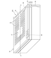
- FIG. 1 is a schematic perspective view of a photonic crystal element according to one embodiment of the present invention.
- the photonic crystal element 100 of the illustrated example has a two-dimensional photonic crystal slab in which pores 12 are periodically formed in a substrate 10 made of a ceramic material.
- a photonic crystal is a multidimensional periodic structure in which a medium having a large refractive index and a medium having a small refractive index are composed of a medium having a period similar to that of light or electromagnetic waves, and has a band structure of light or electromagnetic waves similar to an electron band structure. Have. Therefore, by appropriately designing the periodic structure, a predetermined light or electromagnetic wave forbidden band (photonic band gap) can be expressed.
- a photonic crystal having a forbidden band functions as an object that is neither reflected nor transmitted to light or electromagnetic waves of a predetermined wavelength.
- a line defect is introduced into a photonic crystal having a photonic bandgap, a waveguide mode is formed in the frequency domain of the bandgap, and a waveguide that propagates light or electromagnetic waves with low loss can be realized.
- the photonic crystal element according to the embodiment of the present invention can typically function as a waveguide that guides millimeter waves to terahertz waves.
- the millimeter wave is typically an electromagnetic wave having a frequency of about 30 GHz to 300 GHz; and the terahertz wave is typically an electromagnetic wave having a frequency of about 300 GHz to 20 THz.
- the "photonic crystal element” includes both a wafer on which at least one photonic element is formed (photonic crystal wafer) and a chip obtained by cutting the photonic crystal wafer.
- the photonic crystal in the illustrated example has a two-dimensional photonic crystal slab as described above.
- a two-dimensional photonic crystal slab is a thin plate that uses a dielectric (typically a ceramic material) and is thinned to the wavelength level of electromagnetic waves, and is a material with a refractive index lower than the refractive index of the material that constitutes this thin plate.
- It is a photonic crystal in which the constructed low refractive index portion is provided at an appropriate two-dimensional periodic interval according to the purpose and a desired photonic band gap.
- the pores 12 function as a low refractive index portion
- the portion 14 between the pores 12 and 12 of the substrate 10 functions as a high refractive index portion.
- a portion of the substrate 10 in which the periodic pattern of the holes 12 is not formed becomes a line defect, and the portion of the line defect constitutes the waveguide 16.
- an upper clad and a lower clad having a refractive index lower than that of the thin plate slab may be provided above and below the thin plate slab.
- the upper and lower external environments (air portions) of the photonic crystal element 100 function as the upper clad and the lower clad.
- the substrate 10 is made of a ceramic material as described above. Since the ceramic material that can be used in the embodiment of the present invention has a small dielectric constant (real part) and a small dielectric constant (imaginary part), it is possible to reduce the delay and loss of the electric signal propagating in the photonic crystal. can. Further, the propagation loss in the waveguide can be reduced.
- the substrate is composed of a sintered body of a ceramic material (eg, ceramic powder). Since the sintered body is polycrystalline, the anisotropy in the substrate can be reduced, and therefore the position-dependent characteristics in the photonic crystal element due to the anisotropy (typically, dielectric).
- the ceramic material is preferably polycrystalline or amorphous, more preferably amorphous. Since amorphous can suppress scattering due to grain boundaries peculiar to polycrystals, anisotropy can be further reduced, and the effect of using a ceramic material can be further remarkable.
- a polycrystalline or amorphous ceramic material for example, the complex term (indicating a loss) of the permittivity at a frequency of 0.5 THz or less can be reduced and the variation thereof can be reduced.
- the complex permittivity can be measured by using, for example, terahertz time region spectroscopy.
- semiconductors have been used in many cases as materials constituting photonic crystals. This is because it is easy to form a pore pattern by using a semiconductor process such as photolithography and etching.
- the semiconductor material has a large dielectric constant, the delay of the electric signal propagating in the photonic crystal is large.
- the semiconductor material is a single crystal and has a large anisotropy, and the variation in characteristics (typically, the dielectric constant) depending on the direction in which the electromagnetic wave propagates in the photonic crystal element and the polarization is large.
- ceramic materials particularly sintered bodies have the advantages of low dielectric constant and anisotropy, but are chemically stable and difficult to etch, and are extremely hard and unsuitable for machining.
- the present inventors have holes suitable as a waveguide for millimeter wave to terahertz wave in a sintered body of a ceramic material. It was possible to form a pattern and apply a sintered body of ceramic material to a photonic crystal. The method of forming a photonic crystal will be described later.
- the dielectric constant of the substrate (substantially a ceramic material) at 100 GHz to 10 THz is preferably 3.6 to 11.5, preferably 3.7 when used for an antenna, a bandpass filter, a line, or the like. It is about 10.0, more preferably 3.8 to 9.0. If the dielectric constant is too small, the desired photonic band gap may not be sufficiently formed in the millimeter-wave to terahertz-wave waveguide. If the permittivity is too large, the delay of the electric signal propagating through the photonic crystal may increase.
- the resistivity of the substrate is preferably 100 k ⁇ ⁇ cm or more, more preferably 300 k ⁇ ⁇ cm or more, still more preferably 500 k ⁇ ⁇ cm or more, and particularly preferably 700 k ⁇ ⁇ cm or more. That is all.
- the resistivity is in such a range, the electromagnetic wave can propagate in the material with low loss without affecting the electron conduction.
- this phenomenon is not clear in detail, it can be inferred that if the resistivity is small, the electromagnetic wave is combined with the electron and the energy of the electromagnetic wave is taken away by the electron conduction, resulting in a loss. From this point of view, the larger the resistivity, the more preferable.
- the resistivity can be, for example, 3000 k ⁇ (3 M ⁇ ) ⁇ cm or less.
- the dielectric loss (tan ⁇ ) of the substrate is preferably 0.01 or less, more preferably 0.008 or less, still more preferably 0.006 or less at the frequency used. , Particularly preferably 0.004 or less. If the dielectric loss is in such a range, the propagation loss in the waveguide can be reduced. The smaller the dielectric loss, the more preferable.
- the dielectric loss can be, for example, 0.001 or more.
- the bending strength of the substrate is preferably 50 MPa or more, more preferably 60 MPa or more. If the bending strength is within such a range, the photonic crystal element can be configured as a single layer of the substrate and is not easily deformed. It can be realized. The larger the bending strength, the more preferable. The bending strength can be, for example, 700 MPa or less.
- the coefficient of thermal expansion (linear expansion coefficient) of the substrate is preferably 10 ⁇ 10 -6 / K or less, and more preferably 8 ⁇ 10 -6 / K or less.
- thermal deformation typically, warpage
- a photonic crystal element that can stand on its own as a single layer of the substrate, has sufficient mechanical strength, and has a small change in characteristics is realized by a synergistic effect with the above-mentioned effect of bending strength. be able to.
- the substrate can be made of any suitable ceramic material as long as the above properties can be achieved.
- the ceramic material include quartz, aluminum nitride (AlN), aluminum oxide (Al 2 O 3 ), silicon carbide (SiC), magnesium oxide (Mg O), and spinel (Mg Al 2 O 4 ).
- the thickness of the substrate is preferably 10 ⁇ m to 1 mm, more preferably 0.2 mm to 0.8 mm. When the thickness is within such a range, a photonic crystal element that can stand on its own as a single layer of a substrate and has sufficient mechanical strength can be realized. Further, the propagation loss in the waveguide can be reduced.
- the substrate 10 is periodically formed with holes 12.
- any suitable shape can be adopted as long as a desired photonic band gap can be formed in the waveguide of millimeter wave to terahertz wave.
- Specific examples of the shape of the pores include a substantially spherical shape, an elliptical spherical shape, a substantially cylindrical shape, a polygonal columnar shape (for example, a triangle, a quadrangle, a pentagon, a hexagon, and an octagon in a plan view), and an indeterminate shape.
- the vacancies may be through holes, and for example, a plurality of substantially spherical vacancies may communicate with each other.
- the size of the pores is preferably 10 ⁇ m to 0.8 mm, more preferably 50 ⁇ m to 0.6 mm, and even more preferably 70 ⁇ m to 0.4 mm. If the pore size is in such a range, it is possible to make a photonic band appear in the millimeter wave band and the terahertz wave band. Further, even if a periodic pore structure is formed, a stable photonic crystal element can be realized from the viewpoints of both mechanical strength and long-term reliability.
- the porosity of the substrate is preferably 0.5 ppm to 3000 ppm, more preferably 0.5 ppm to 1000 ppm, and further preferably 0.5 ppm to 100 ppm for pores having a pore size of 1 ⁇ m or more. If the porosity is within such a range, densification is possible, and further, due to the synergistic effect with the above-mentioned effect of setting the pore size within a predetermined range, even if a periodic pore structure is formed, the mechanical strength and long-term reliability are achieved.
- a stable photonic crystal device can be realized from any viewpoint of sex.
- the shape of the pores can be made uniform without variation, the wavelength-dependent characteristics of the transmittance due to the photonic band become clear, and the hand band can be widened. .. If the porosity exceeds 3000 ppm, the propagation loss in the waveguide may increase. It is difficult to make the porosity less than 0.5 ppm by the technique using a sintered body of a ceramic material.
- the “pores” mean bubbles (micropores) possessed by the substrate (ceramic material) itself, and are different from the pores formed to form a photonic crystal.
- the size of the pores or pores is the diameter when the pores or pores are substantially spherical, the diameter when viewed in a plan view when the pores are substantially cylindrical, and the diameter when the pores have other shapes.
- the presence or absence of pores or pores can be confirmed by, for example, an optical CT (Computed Tomography) or a transmittance measuring device.
- the size of the pores or pores can be measured, for example, by a scanning electron microscope (SEM). Since the pores are relatively large in size, they can also be measured with a stereomicroscope or a laser shape measuring instrument.
- the pores 12 can be formed as a periodic pattern as described above.
- the holes 12 are typically arranged to form a regular grid.
- any suitable form can be adopted as long as a desired photonic band gap can be realized in the waveguide of millimeter wave to terahertz wave. Typical examples include a triangular lattice and a square lattice.
- the grid pattern of the pores can be appropriately set according to the purpose and the desired photonic band gap.
- the pores having a diameter d form a square grid with a period P.
- the square lattice pattern is formed on both sides of the photonic crystal element, and the waveguide 16 is formed in the central portion where the lattice pattern is not formed.
- the width of the waveguide 16 can be, for example, 1.01P to 3P (2P in the illustrated example) with respect to the pore period P.
- the number of rows of vacancies in the direction of the waveguide (hereinafter, may be referred to as grid rows) can be 3 to 10 rows (5 rows in the illustrated example) on each side of the waveguide.
- the pore period P may satisfy, for example, the following relationship.
- ⁇ is the wavelength (nm) of light or electromagnetic wave introduced into the waveguide
- n is the refractive index of the substrate. Since the refractive index ⁇ r is proportional to the 1/2 power of the dielectric constant, “n” in the above equation may be replaced with “( ⁇ r) 1/2 ”.
- the pore period P is preferably 10 ⁇ m to 1 mm, more preferably 0.2 mm to 0.8 mm. In one embodiment, the pore period P can be comparable to the thickness of the sintered body (substrate).
- the diameter d of the pores is preferably 0.1P to 0.9P, more preferably 0.2P to 0.6P, with respect to the pore period P.
- the width of the grid pattern is preferably 10P or more, and more preferably 12P to 20P.
- the width of the grid pattern is the distance between the outermost grid pattern in the grid pattern on one side of the waveguide and the outermost grid row in the grid pattern on the other side of the waveguide. Therefore, as shown in the illustrated example, the width of the grid pattern on one side of the waveguide is 4P or more.
- the waveguide 16 has a band shape (straight line shape), but by changing the lattice pattern, it is possible to form a waveguide having a predetermined shape (hence, a predetermined waveguide direction).
- the waveguide may extend in a direction (oblique direction) having a predetermined angle with respect to the long side direction or the short side direction of the photonic crystal element, or may bend at a predetermined point (waveguide direction). May change at a given point).
- the two-dimensional photonic crystal slab can be made by near-net molding of a powder sintering method (substantially, slurry casting molding).
- a powder sintering method substantially, slurry casting molding
- near-net molding of a powder sintering method substantially, slurry casting molding
- the two-dimensional photonic crystal slab may be formed by machining a wafer.
- the protrusions can form pores in the resulting sintered body. Therefore, the shape, size, and the like of the protrusions can be designed according to the shape, size, and the like of the pores formed in the obtained sintered body. In one embodiment, the protrusions can form through holes.
- a slurry containing a ceramic material powder and a predetermined dispersant and a dispersion medium is poured into the molding die.
- the dispersant can be appropriately selected depending on the ceramic material.
- the dispersant is typically an organic compound, more specifically a resin.
- the dispersion medium may be an aqueous system or an organic solvent system. Examples of the aqueous dispersion medium include water and water-soluble alcohol. Examples of the organic solvent-based dispersion medium include paraffin, toluene, and petroleum ether.
- the slurry is prepared, for example, by mixing a ceramic material powder, a dispersant, a dispersion medium and, if necessary, other components (eg, additives). Examples of the mixing means include a ball mill pot, a homogenizer, and a disperser.
- a sintered body (substrate: two-dimensional photonic crystal slab) of a ceramic material having a predetermined pore pattern can be obtained.
- Firing to obtain a sintered body typically includes a calcining step and, if necessary, a calcination step performed before the calcining step.
- the calcination temperature is preferably 1000 ° C. or higher and lower than 1250 ° C., and more preferably 1000 ° C. to 1200 ° C. When the calcination temperature is in such a range, a sintered body having excellent transparency can be obtained.
- the firing temperature is preferably 1500 ° C to 1700 ° C.
- the rate of temperature rise during firing is preferably 20 ° C./min or higher at 1000 ° C. or higher, preferably 20 ° C./min or higher at 1200 ° C. or higher, and more preferably 25 ° C./min or higher.
- degreasing is performed prior to firing.
- the degreasing temperature is preferably 300 ° C to 800 ° C.
- the above-mentioned temporary baking may also serve as degreasing. Degreasing at 1200 ° C. or lower can suppress the precipitation of the crystalline phase.
- a desired sintered body (substrate) can be obtained.
- a desired sintered body (substrate) can be obtained.
- a predetermined pore pattern can be easily applied to the sintered body of a ceramic material. Moreover, it can be formed at low cost. As a result, a photonic crystal device having a small delay of an electric signal, a small propagation loss, and uniform characteristics over the entire device can be obtained easily and at low cost.
- the frequency suitable for the photonic crystal element manufactured by such a method is preferably 125 / ⁇ GHz to 15000 / ⁇ GHz, where the relative permittivity of the substrate material is ⁇ .
- the photonic crystal element 101 of the illustrated example includes a support substrate 30 provided under the substrate 10 and supporting the substrate 10, a joint portion 20 for integrating the substrate 10 and the support substrate 30, and a lower surface and a support of the substrate 10. It further has a cavity 80 defined by an upper surface of the substrate 30 and a joint 20.
- any suitable configuration may be adopted for the support substrate 30.
- the materials constituting the support substrate 30 include silicon (Si), glass, Sialon (Si 3 N 4 -Al 2 O 3 ), and Murite ( 3 Al 2 O 3.2SiO 2 , 2Al 2 O 3.3SiO 2 ). ), Aluminum nitride (AlN), Silicon nitride (Si 3N 4 ) , Magnesium oxide (MgO), Aluminum oxide (Al 2 O 3 ), Spinel (Mg Al 2 O 4 ), Sapphire, Quartz, Crystal, Gallium nitride (GaN) ), Silicon carbide (SiC), gallium oxide (Ga 2 O 3 ).
- Such a material can be integrated with a semiconductor circuit such as an amplifier or a mixer when used at the front end of a millimeter wave to a terahertz wave (for example, as an antenna substrate).
- the coefficient of linear expansion of the material constituting the support substrate 30 is preferably closer to the coefficient of linear expansion of the material constituting the substrate 10. With such a configuration, thermal deformation (typically, warpage) of the photonic crystal element can be suppressed.
- the coefficient of linear expansion of the material constituting the support substrate 30 is in the range of 50% to 150% with respect to the coefficient of linear expansion of the material constituting the substrate 10. From this point of view, the support substrate may be made of the same material as the substrate 10.
- the joint portion 20 is interposed between the substrate 10 and the support substrate 30 to integrate them.
- the joint 20 is configured as the rest of the etching in forming the cavity 80.
- the joint portion 20 typically integrates the substrate 10 and the support substrate 30 by directly joining the upper layer and the lower layer. By integrating the substrate 10 and the support substrate 30 by direct bonding, peeling in the photonic crystal element can be satisfactorily suppressed.
- direct bonding means that two layers or substrates (here, an upper layer and a lower layer) are bonded without the intervention of an adhesive.
- the form of direct bonding can be appropriately set depending on the configuration of the layers or substrates to be bonded to each other.
- direct joining can be realized by the following procedure. In a high vacuum chamber (for example, about 1 ⁇ 10 -6 Pa), a neutralized beam is irradiated to the respective joint surfaces of the upper layer and the lower layer. As a result, each joint surface is activated. Then, in a vacuum atmosphere, the activated joining surfaces are brought into contact with each other and joined at room temperature.
- the load at the time of this joining can be, for example, 100N to 20000N.
- an inert gas is introduced into the chamber, and a high voltage is applied from a DC power source to the electrodes arranged in the chamber.
- a high voltage is applied from a DC power source to the electrodes arranged in the chamber.
- electrons move due to the electric field generated between the electrode (positive electrode) and the chamber (negative electrode), and a beam of atoms and ions due to the inert gas is generated.
- the ion beam is neutralized by the grid, so that the beam of neutral atoms is emitted from the high-speed atomic beam source.
- the atomic species constituting the beam is preferably an inert gas element (for example, argon (Ar), nitrogen (N)).
- the voltage at the time of activation by beam irradiation is, for example, 0.5 kV to 2.0 kV, and the current is, for example, 50 mA to 200 mA.
- the direct bonding method is not limited to this, and FAB (Fast Atom Beam), a surface activation method using an ion gun, an atomic diffusion method, a plasma bonding method, and the like can also be applied. Any suitable configuration may be adopted for the upper layer and the lower layer, respectively, depending on the purpose.
- the cavity 80 is formed by removing the upper layer and the lower layer by etching as described above, and can function as a lower clad.
- the width of the cavity is preferably larger than the width of the optical waveguide.
- the photonic crystal element according to the embodiment of the present invention is used for, for example, an antenna, a bandpass filter, a coupler, a delay line (phase detector), or an isolator. Since these can be realized without using metal wiring, it is possible to suppress conductor loss due to the skin effect and radiation loss due to scattering.
- the photonic crystal device is an active device capable of transmitting, receiving, and amplifying at least one of electromagnetic waves having a frequency of 30 GHz or more and 20 THz or less. Therefore, an active element supported by the support substrate may be provided. In such a photonic crystal element, the active element and the line substrate can be integrated to enable a wafer process, so that variation in characteristics can be reduced and the productivity of the photonic crystal element can be improved. Therefore, an inexpensive photonic crystal element can be realized.
- a configuration is configured in which an electromagnetic wave can be propagated between the waveguide of line defects formed in a two-dimensional photonic crystal slab and the active element.
- the photonic crystal element 102 shown in FIGS. 3 to 5 is formed between the first waveguide of the line defect formed in the two-dimensional photonic crystal slab and the active element and the first waveguide in the electromagnetic wave propagation path. It is located and has a second waveguide (typically a coplanar waveguide in the illustrated example) capable of waveguideing electromagnetic waves.
- the second waveguide is capable of waveguideing an electromagnetic wave transmitted from an active element into the first waveguide.
- the photonic crystal element 102 includes a two-dimensional photonic crystal slab 90 in which pores 12 are periodically formed in a ceramic material substrate 10, and a support provided below the substrate 10 to support the substrate 10. It includes a substrate 30, an active element 40 supported by the support substrate 30, and a coplanar type electrode pattern 50.
- the two-dimensional photonic crystal slab 90 has a photonic crystal portion 90a in which pores 12 are periodically formed in the substrate 10 and a portion in which the pores 12 are not formed in the photonic crystal portion 90a (substrate 10). It includes a defined line defect waveguide 16 and other portions 90b other than the photonic crystal portion 90a. The other portion 90b is typically not formed with a hole 12.
- the support substrate 30 has a recess 31.
- the recess 31 is recessed downward from the upper surface of the support substrate 30.
- the recess 31 is typically open toward one of the waveguide directions of the waveguide 16.
- the lower surface of the ceramic material substrate 10 and the recess 31 of the support substrate 30 define a cavity 81.
- the photonic crystal element 102 includes the cavity 81.
- the cavity 81 is a low dielectric constant portion and functions as a lower clad. Since the photonic crystal element is provided with a cavity, it is possible to stably suppress the leakage of electromagnetic waves propagating in the waveguide from the waveguide.
- the cavity 81 typically overlaps the waveguide 16 in the thickness direction of the substrate 10, and the width of the cavity 81 (dimensions in the direction orthogonal to the waveguide direction of the waveguide 16) is larger than the width of the waveguide 16. big.
- the cavity 81 preferably extends from the optical waveguide 16 to at least a third grid row. Electromagnetic waves not only propagate in the waveguide, but part of the electromagnetic waves may diffuse to the grid array near the waveguide. Therefore, by providing a cavity directly under such a grid array, propagation loss is suppressed. be able to. From this point of view, it is more preferable that the cavity 81 extends from the waveguide 16 to the fifth row, and it is particularly preferable that the cavity 81 extends so as to overlap the entire area of the photonic crystal portion 90a as shown in the illustrated example.
- the ceramic material substrate 10 two-dimensional photonic crystal slab 90
- the support substrate 30 are directly bonded by a bonding portion 20.
- the joint portion 20 is interposed between the other portion 90b of the two-dimensional photonic crystal slab 90 and the portion other than the recess 31 of the support substrate 30 to integrate the substrate 10 and the support substrate 30. do.
- the active element 40 is supported by the support substrate 30, and is typically embedded in a portion of the upper surface of the support substrate 30 other than the recess 31.
- Examples of the active element 40 include a resonance tunnel diode, a Schottky barrier diode, a CMOS transceiver, and an InPHEMT.
- the active element 40 is a resonant tunneling diode.
- the active element 40 can transmit (generate / radiate) electromagnetic waves.
- the active element 40 includes a first element electrode 41 and two second element electrodes 42. Each of the first element electrode 41 and the two second element electrodes 42 extends in the waveguide direction of the waveguide 16.
- the two second element electrodes 42 are arranged so as to be spaced apart from each other in a direction orthogonal to the waveguide direction of the waveguide 16.
- the first element electrode 41 is arranged between the two second element electrodes 42.
- the coplanar type electrode pattern 50 is arranged on a portion (that is, other portions 90b) other than the photonic crystal portion 90a in the ceramic material substrate 10.
- the coplanar electrode pattern 50 and the other portion 90b located below the coplanar electrode pattern 50 constitute a coplanar waveguide as an example of the second waveguide.
- the coplanar type electrode pattern 50 is aligned with the waveguide 16 in the waveguide direction.
- the coplanar type electrode pattern 50 includes a signal electrode 51 extending in the waveguide direction of the waveguide 16 and a plan-view U-shaped ground electrode 52 opened toward the waveguide 16.
- the signal electrode 51 is arranged inside the ground electrode 52, and is arranged at a distance from the ground electrode 52.
- the signal electrode 51 is electrically connected to the first element electrode 41 of the active element 40 via the via 43.
- the ground electrode 52 is electrically connected to the second element electrode 42 of the active element 40 via two vias 44.
- the second waveguide is not limited to the coplanar waveguide, and may be configured as, for example, a microstrip waveguide or a waveguide integrated waveguide.
- the propagation of electromagnetic waves in the photonic crystal element 102 will be described.
- a voltage is applied to the coplanar type electrode pattern 50, an electric field is generated between the signal electrode 51 and the ground electrode 52.
- the active element 40 transmits an electromagnetic wave.
- the electromagnetic wave transmitted from the active element 40 propagates toward the signal electrode 51 via the via 43, and then combines with the electric field formed between the signal electrode 51 and the ground electrode 52 to pass through the substrate 10. It propagates toward the waveguide 16 of the line defect.
- the electromagnetic wave transmitted from the active element 40 is first propagated to the coplanar waveguide.
- the electromagnetic wave is then propagated from the coplanar waveguide to the line defect waveguide 16 and then to the line defect waveguide 16.
- the photonic crystal element 103 shown in FIGS. 6 to 8 is a waveguide 16 having a line defect formed in the two-dimensional photonic crystal slab and a resonator 17 formed in the two-dimensional photonic crystal slab.
- a resonator 17 located between the active element 40 and the waveguide 16 in the propagation path of the electromagnetic wave and capable of guiding the electromagnetic wave is provided.
- the resonator is capable of waveguideing an electromagnetic wave transmitted from an active element into a waveguide.
- the two-dimensional photonic crystal slab 91 included in the photonic crystal element 103 has a line defect waveguide 16 defined as a portion in which the pores 12 are not formed, and a portion in which the pores 12 are not formed.
- a defined mode gap closed type resonator 17 is provided.
- the resonator 17 can receive the electromagnetic wave transmitted from the active element 40, and can send the received electromagnetic wave to the waveguide 16.
- the resonator 17 is aligned with the waveguide 16 in the waveguide direction of the waveguide 16 and is continuous with the waveguide 16.
- the width of the resonator 17 (dimension in the direction orthogonal to the waveguide direction of the waveguide 16) is larger than the width of the waveguide 16.
- the resonator 17 is formed by being surrounded by a row of three rows of holes.
- the photonic crystal element 103 includes an insulating layer 23 located between the ceramic material substrate 10 (two-dimensional photonic crystal slab 91) and the support substrate 30.
- the material of the insulating layer 23 include the above-mentioned ceramic materials, and preferably quartz glass.
- the ceramic material substrate 10 two-dimensional photonic crystal slab 90
- the insulating layer 23 are directly bonded by the bonding portion 21, and the support substrate 30 and the insulating layer 23 are directly bonded by the bonding portion 22. It is joined.
- the joint portion 21 is interposed between the substrate 10 and the insulating layer 23 to integrate the substrate 10 and the insulating layer 23.
- the joint portion 22 is interposed between the insulating layer 23 and the support substrate 30 to integrate the insulating layer 23 and the support substrate 30.
- the insulating layer 23 in the illustrated example has a U-shape in a plan view that is open toward one of the waveguide directions of the waveguide 16.
- the lower surface of the ceramic material substrate 10, the upper surface of the support substrate 30, and the insulating layer 23 define a cavity 82.
- the cavity 82 may be defined by a lower surface of the substrate 10, a joint 22 located on the upper surface of the support substrate 30, and an insulating layer 23.
- the photonic crystal element 103 includes the cavity 82.
- the cavity 82 typically overlaps the waveguide 16 and the resonator 17 in the thickness direction of the substrate 10, and the width of the cavity 82 (dimensions in the direction orthogonal to the waveguide direction of the waveguide 16) is the resonator. It is larger than the width of 17.
- the cavity 82 preferably extends from each of the waveguide 16 and the resonator 17 to the third row of grids and overlaps the entire pore-forming portion of the two-dimensional photonic crystal slab 91, as shown in the illustrated example. It is particularly preferable that it extends like this.
- the propagation of electromagnetic waves in the photonic crystal element 103 will be described.
- the first element electrode 41 functions as an antenna, and electromagnetic waves are transmitted from the first element electrode 41 toward the resonator 17.
- the electromagnetic wave that has reached the resonator 17 is received by the resonator 17 and then sent out from the resonator 17 to the waveguide 16 via a continuous portion between the resonator 17 and the waveguide 16. After that, the electromagnetic wave is propagated in the waveguide 16.
- 3 to 8 show an example in which the active element functions to transmit (generate / radiate) an electromagnetic wave, and the electromagnetic wave transmitted from the active element is coupled to a line defect waveguide via a second waveguide or a resonator.
- the active element functions to receive the electromagnetic wave, and the electromagnetic wave waveguideed through the line defect waveguide is coupled to the active element via the second waveguide or the resonator. Is easily assumed.
- the two-dimensional photonic crystal slab included in the photonic crystal element of the present invention is not limited to the two-dimensional photonic crystal slab including the waveguide of the line defect described above.
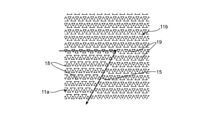
- the two-dimensional photonic crystal slab may be a valley photonic crystal layer 11 in which the boundary of a region composed of two different unit cells functions as a waveguide.
- the valley photonic crystal layer 11 includes a first region 11a composed of a plurality of first unit cells 18 and a second region 11b composed of a plurality of second unit cells 19.
- the first region 11a and the second region 11b are adjacent to each other, and the boundary portion between the first region 11a and the second region 11b is configured as the waveguide 15.
- Each of the first unit cell 18 and the second unit cell 19 is formed with two types of pores having different sizes periodically formed on the ceramic material substrate 10.
- the vacancies are typically arranged to form a regular grid.
- any suitable form can be adopted as long as a desired photonic band gap can be realized in the waveguide of millimeter wave to terahertz wave.
- first unit cell 18 and the second unit cell 19 of the illustrated example three relatively large first holes 12a and three relatively small second holes 12b are formed as a honeycomb lattice (hexagonal lattice). Is arranged to form a honeycomb. In each unit cell, the first holes 12a and the second holes 12b are arranged alternately.
- the first unit cell 18 and the second unit cell 19 have a 180 ° rotational symmetry (line symmetry) relationship. The first unit cell 18 coincides with the second unit cell 19 when rotated by 180 ° about the center of the grid.
- Each of the first hole 12a and the second hole 12b typically has a regular triangular shape.
- the length L of one side of the first hole 12a satisfies the following formula (1)
- the length S of one side of the second hole 12b satisfies the following formula (2).
- L is the length of one side of the first hole ( ⁇ m)
- S is the length of one side of the second hole ( ⁇ m)
- a is the distance between the opposite sides in the honeycomb lattice. ( ⁇ m).
- the distance between the opposite sides in the honeycomb lattice is, for example, 250 ⁇ m or more and 500 ⁇ m or less, and particularly preferably 400 ⁇ m in the case of a frequency of 300 GHz.
- the waveguide 15 is capable of waveguideing millimeter waves to terahertz waves, and is formed at the boundary between the first region 11a and the second region 11b.
- the waveguide 15 in the illustrated example is bent at a predetermined point (the waveguide direction is changed at a predetermined point), the shapes of the first region 11a and the second region 11b are changed to change the shapes of the first region 11a and the second region 11b.
- the boundary shape of the above it is possible to form a waveguide having a desired shape.
- the waveguide may extend linearly along the long side direction or the short side direction of the photonic crystal element without bending, and may be predetermined with respect to the long side direction or the short side direction of the photonic crystal element. It may extend in a direction having an angle of (diagonal direction).
- a photonic crystal element as shown in FIG. 1 was manufactured by near-net molding by a powder sintering method (substantially, slurry casting molding). Specifically, it is as follows. A mold with protrusions corresponding to the pore pattern is sufficiently mixed with a fine powder of amorphous quartz, a hydrophilic dispersant (organic compound) that decomposes or volatilizes by pre-baking, and a dispersion medium (water) to remove water. A slurry for near net molding of 15% by weight to 30% by weight was prepared. This slurry was cast into a molding die, and the slurry was solidified by utilizing a chemical reaction of an organic compound.
- a powder sintering method substantially, slurry casting molding. Specifically, it is as follows. A mold with protrusions corresponding to the pore pattern is sufficiently mixed with a fine powder of amorphous quartz, a hydrophilic dispersant (organic compound) that decomposes or volatilizes by pre-
- the solidified product was released from the mold and fired at a high temperature to produce a photonic crystal device in which a periodic pore pattern was formed in the sintered body.
- the molding die was designed in consideration of the firing shrinkage rate so that the desired dimensions could be obtained after firing.
- the produced photonic crystal element had a size of 30 mm ⁇ 30 mm, a thickness of 0.5 mm, a pore diameter of 0.2 mm, and a pore period of 0.5 mm.
- a waveguide having a width of 1 mm was formed by providing a portion that does not form a single row hole in the central portion. In order to measure the propagation loss of the waveguide, three photonic crystal elements having a waveguide length of 10 mm, 30 mm, and 50 mm were manufactured.
- the resistivity of the substrate constituting the photonic crystal element was 1 M ⁇ ⁇ cm.
- the propagation loss of the three obtained photonic crystal elements was measured as follows. The RF signal generator and the transmitting antenna in the 300 GHz band were coupled to the input side of the photonic crystal element, the receiving antenna and the RF signal receiver were coupled to the output side, and the RF power was measured by the RF signal receiver. The propagation loss (dB / cm) was calculated from the measurement results of the three photonic crystal elements. The delay of the electric signal is calculated from the phase difference of the photonic crystal elements having different waveguide lengths by measuring the phase in the RF signal receiver, and the transmission time (unit: picoseconds) of Comparative Example 1 is calculated. The delay ratio when it was set to 1 was obtained. In addition, the dielectric loss tan ⁇ of the material at 300 GHz was measured. The measurement was carried out by transmission measurement using a terahertz non-destructive measuring instrument manufactured by Japan Precision. The above results are shown in Table 1.
- a photonic crystal element as shown in FIG. 1 was produced by using single crystal quartz (quartz) instead of amorphous quartz. Specifically, it is as follows.
- a 4-inch crystal wafer with a thickness of 0.5 mm was prepared. In this wafer (board), the direction parallel to the main orientation is the normal optical axis, and the direction orthogonal to the main orientation is the abnormal optical axis.
- the same pore pattern and waveguide as in Example 1 were formed on this wafer by ultrasonic spindle processing.
- a photonic crystal element I in which the direction of the waveguide is parallel to the normal optical axis and a photonic crystal element II in which the direction of the waveguide is parallel to the abnormal optical axis were manufactured.
- photonic crystal elements I and II three photonic crystal elements having waveguide lengths of 10 mm, 30 mm, and 50 mm were produced, respectively.
- the substrate was cut into 30 mm ⁇ 30 mm.
- the resistivity of the substrate constituting the photonic crystal element was 1 M ⁇ ⁇ cm.
- the obtained photonic crystal element was subjected to the same evaluation as in Example 1. Furthermore, the presence or absence of characteristic variation due to anisotropy was evaluated from the propagation loss of the photonic crystal elements I and II. The results are shown in Table 1.
- a photonic crystal element as shown in FIG. 1 was manufactured by using polycrystalline aluminum nitride instead of amorphous quartz. Specifically, it is as follows. A 4-inch polycrystalline aluminum nitride wafer having a thickness of 0.32 mm was prepared. A pore pattern having a pore diameter of 0.08 mm and a pore period of 0.32 mm was formed on this wafer (board) by ultrasonic spindle processing. A waveguide having a width of 0.64 mm was formed by providing a portion not forming a single row hole in the central portion. In order to measure the propagation loss of the waveguide, three photonic crystal elements having a waveguide length of 10 mm, 30 mm, and 50 mm were manufactured.
- the substrate was cut into 30 mm ⁇ 30 mm.
- the resistivity of the substrate constituting the photonic crystal element was 1 M ⁇ ⁇ cm.
- the obtained photonic crystal element was subjected to the same evaluation as in Example 1. The results are shown in Table 1.
- a photonic crystal element as shown in FIG. 1 was manufactured by using single crystal silicon instead of amorphous quartz. Specifically, it is as follows. Single crystal silicon of 4 inches and a thickness of 0.3 mm was prepared. A pore pattern having a pore diameter of 0.075 mm and a pore period of 0.3 mm was formed on this wafer (board) by ultrasonic spindle processing. A waveguide having a width of 0.6 mm was formed by providing a portion not forming a single row hole in the central portion. In order to measure the propagation loss of the waveguide, three photonic crystal elements having a waveguide length of 10 mm, 30 mm, and 50 mm were manufactured.
- the substrate was cut into 30 mm ⁇ 30 mm.
- the resistivity of the substrate constituting the photonic crystal element was 10 k ⁇ ⁇ cm.
- the obtained photonic crystal element was subjected to the same evaluation as in Example 1. The results are shown in Table 1.
- the photonic crystal element of the embodiment of the present invention using the ceramic material has a significantly smaller delay amount of the electric signal than the photonic crystal element of Comparative Example 1 using the semiconductor material. Can be done. In addition, the propagation loss can be reduced. Further, as is clear when comparing Examples 1 and 3 with Example 2, by using a polycrystalline or amorphous material for the substrate, characteristic variation due to anisotropy as in the case of using a single crystal (here). Then, propagation loss) can be prevented.
- the photonic crystal element according to the embodiment of the present invention can be used in a wide range of fields such as optical waveguide, next-generation high-speed communication, sensor, laser processing, and photovoltaic power generation, and is particularly suitable as a millimeter-wave to terahertz-wave waveguide. Can be used.
- Such photonic crystal elements can be used, for example, in antennas, bandpass filters, couplers, delay lines (phase detectors), or isolators.
Landscapes
- Physics & Mathematics (AREA)
- Nonlinear Science (AREA)
- General Physics & Mathematics (AREA)
- Optics & Photonics (AREA)
- Electromagnetism (AREA)
- Engineering & Computer Science (AREA)
- Microelectronics & Electronic Packaging (AREA)
- Optical Integrated Circuits (AREA)
- Waveguide Connection Structure (AREA)
- Waveguides (AREA)
- Control Of Motors That Do Not Use Commutators (AREA)
- Aerials With Secondary Devices (AREA)
Abstract
L'invention concerne un dispositif à cristal photonique présentant un faible retard de signal électrique, une faible perte de propagation et des caractéristiques uniformes dans tout le dispositif. Le dispositif à cristal photonique présente une plaque de cristal photonique bidimensionnelle dans laquelle des pores sont périodiquement formés dans un substrat composé d'un matériau céramique et guide une onde électromagnétique présentant une fréquence de 30 GHz à 20 THz.
Priority Applications (5)
| Application Number | Priority Date | Filing Date | Title |
|---|---|---|---|
| JP2021567018A JP7285340B2 (ja) | 2020-07-27 | 2021-07-26 | フォトニック結晶素子 |
| DE112021003953.9T DE112021003953T5 (de) | 2020-07-27 | 2021-07-26 | Photonisches Kristallelement |
| JP2021192760A JP7108118B2 (ja) | 2020-07-27 | 2021-11-29 | フォトニック結晶素子 |
| JP2021192761A JP7108119B2 (ja) | 2020-07-27 | 2021-11-29 | フォトニック結晶素子 |
| US18/062,733 US20230112992A1 (en) | 2020-07-27 | 2022-12-07 | Photonic crystal element |
Applications Claiming Priority (2)
| Application Number | Priority Date | Filing Date | Title |
|---|---|---|---|
| JP2020-126208 | 2020-07-27 | ||
| JP2020126208 | 2020-07-27 |
Related Child Applications (1)
| Application Number | Title | Priority Date | Filing Date |
|---|---|---|---|
| US18/062,733 Continuation US20230112992A1 (en) | 2020-07-27 | 2022-12-07 | Photonic crystal element |
Publications (1)
| Publication Number | Publication Date |
|---|---|
| WO2022025009A1 true WO2022025009A1 (fr) | 2022-02-03 |
Family
ID=80036200
Family Applications (1)
| Application Number | Title | Priority Date | Filing Date |
|---|---|---|---|
| PCT/JP2021/027594 Ceased WO2022025009A1 (fr) | 2020-07-27 | 2021-07-26 | Dispositif à cristal photonique |
Country Status (4)
| Country | Link |
|---|---|
| US (1) | US20230112992A1 (fr) |
| JP (3) | JP7285340B2 (fr) |
| DE (1) | DE112021003953T5 (fr) |
| WO (1) | WO2022025009A1 (fr) |
Cited By (2)
| Publication number | Priority date | Publication date | Assignee | Title |
|---|---|---|---|---|
| JP2023180718A (ja) * | 2022-06-10 | 2023-12-21 | 沖電気工業株式会社 | 光導波路素子 |
| DE102024107297A1 (de) * | 2024-03-14 | 2025-09-18 | Universität Duisburg-Essen, Körperschaft des öffentlichen Rechts | Drahtlose Detektion von Pathogen in Luft mit photonischem Kristall |
Families Citing this family (2)
| Publication number | Priority date | Publication date | Assignee | Title |
|---|---|---|---|---|
| JP2542202B2 (ja) | 1986-11-24 | 1996-10-09 | 株式会社 メレツク | ステッピングモ―タの微小角駆動方法とその装置 |
| JP3266557B2 (ja) | 1997-10-07 | 2002-03-18 | マイコム株式会社 | ステッピングモータの微小角駆動装置 |
Citations (6)
| Publication number | Priority date | Publication date | Assignee | Title |
|---|---|---|---|---|
| JP2003227953A (ja) * | 2002-02-06 | 2003-08-15 | Matsushita Electric Ind Co Ltd | フォトニック結晶集光素子、フォトニック結晶集光光源、および光ディスク装置 |
| JP2005274840A (ja) * | 2004-03-24 | 2005-10-06 | Ricoh Co Ltd | 光遅延素子 |
| WO2010073708A1 (fr) * | 2008-12-26 | 2010-07-01 | 日本電気株式会社 | Filtre de longueur d'onde |
| JP2015162787A (ja) * | 2014-02-27 | 2015-09-07 | 国立大学法人大阪大学 | 方向性結合器および合分波器デバイス |
| JP2015187716A (ja) * | 2014-03-12 | 2015-10-29 | 国立大学法人大阪大学 | テラヘルツ波デバイス、およびテラヘルツ波集積回路 |
| JP2019082518A (ja) * | 2017-10-30 | 2019-05-30 | 有限会社オートクローニング・テクノロジー | 光マトリクススイッチ |
Family Cites Families (8)
| Publication number | Priority date | Publication date | Assignee | Title |
|---|---|---|---|---|
| JP4658405B2 (ja) | 2001-08-23 | 2011-03-23 | 三菱電機株式会社 | 高周波用導波路とその製造方法 |
| WO2003034113A2 (fr) | 2001-10-19 | 2003-04-24 | Nkt Research & Innovation A/S | Structure de cristal photonique integre et procede de production associe |
| GB0302654D0 (en) | 2003-02-05 | 2003-03-12 | Univ Cambridge Tech | Processes of forming small diameter rods and tubes |
| JP4327797B2 (ja) | 2003-03-26 | 2009-09-09 | Tdk株式会社 | 二次元フォトニック結晶、ならびにそれを用いた導波路および共振器 |
| JP2008035017A (ja) | 2006-07-27 | 2008-02-14 | Murata Mfg Co Ltd | 2次元周期構造を有する高周波デバイス |
| JP4785194B2 (ja) * | 2006-08-25 | 2011-10-05 | 日本碍子株式会社 | スラブ型2次元フォトニック結晶構造の製造方法 |
| JP2008299031A (ja) | 2007-05-31 | 2008-12-11 | Canon Inc | フォトニック結晶構造およびその製造方法 |
| JP6281868B2 (ja) | 2013-03-08 | 2018-02-21 | 国立大学法人大阪大学 | フォトニック結晶スラブ電磁波吸収体および高周波金属配線回路、電子部品、および送信器、受信器および近接無線通信システム |
-
2021
- 2021-07-26 WO PCT/JP2021/027594 patent/WO2022025009A1/fr not_active Ceased
- 2021-07-26 DE DE112021003953.9T patent/DE112021003953T5/de active Pending
- 2021-07-26 JP JP2021567018A patent/JP7285340B2/ja active Active
- 2021-11-29 JP JP2021192760A patent/JP7108118B2/ja active Active
- 2021-11-29 JP JP2021192761A patent/JP7108119B2/ja active Active
-
2022
- 2022-12-07 US US18/062,733 patent/US20230112992A1/en active Pending
Patent Citations (6)
| Publication number | Priority date | Publication date | Assignee | Title |
|---|---|---|---|---|
| JP2003227953A (ja) * | 2002-02-06 | 2003-08-15 | Matsushita Electric Ind Co Ltd | フォトニック結晶集光素子、フォトニック結晶集光光源、および光ディスク装置 |
| JP2005274840A (ja) * | 2004-03-24 | 2005-10-06 | Ricoh Co Ltd | 光遅延素子 |
| WO2010073708A1 (fr) * | 2008-12-26 | 2010-07-01 | 日本電気株式会社 | Filtre de longueur d'onde |
| JP2015162787A (ja) * | 2014-02-27 | 2015-09-07 | 国立大学法人大阪大学 | 方向性結合器および合分波器デバイス |
| JP2015187716A (ja) * | 2014-03-12 | 2015-10-29 | 国立大学法人大阪大学 | テラヘルツ波デバイス、およびテラヘルツ波集積回路 |
| JP2019082518A (ja) * | 2017-10-30 | 2019-05-30 | 有限会社オートクローニング・テクノロジー | 光マトリクススイッチ |
Cited By (2)
| Publication number | Priority date | Publication date | Assignee | Title |
|---|---|---|---|---|
| JP2023180718A (ja) * | 2022-06-10 | 2023-12-21 | 沖電気工業株式会社 | 光導波路素子 |
| DE102024107297A1 (de) * | 2024-03-14 | 2025-09-18 | Universität Duisburg-Essen, Körperschaft des öffentlichen Rechts | Drahtlose Detektion von Pathogen in Luft mit photonischem Kristall |
Also Published As
| Publication number | Publication date |
|---|---|
| US20230112992A1 (en) | 2023-04-13 |
| JP7108118B2 (ja) | 2022-07-27 |
| JP2022040119A (ja) | 2022-03-10 |
| JP7285340B2 (ja) | 2023-06-01 |
| JP7108119B2 (ja) | 2022-07-27 |
| JPWO2022025009A1 (fr) | 2022-02-03 |
| JP2022036087A (ja) | 2022-03-04 |
| DE112021003953T5 (de) | 2023-06-07 |
Similar Documents
| Publication | Publication Date | Title |
|---|---|---|
| JP7108118B2 (ja) | フォトニック結晶素子 | |
| Liu et al. | Enhancement of the gain for microstrip antennas using negative permeability metamaterial on low temperature co-fired ceramic (LTCC) substrate | |
| McKinzie et al. | 60-GHz $2\times 2$ LTCC patch antenna array with an integrated EBG structure for gain enhancement | |
| Zheng et al. | A compact waveguide slot filtering antenna based on mushroom-type surface | |
| US20230411818A1 (en) | Waveguide element | |
| Oskouei et al. | Guided and leaky wave characteristics of periodic defected ground structures | |
| Chang et al. | Planar air-filled terahertz antenna array based on channelized coplanar waveguide using hierarchical silicon bulk micromachining | |
| US20240186672A1 (en) | Waveguide device | |
| JP7602995B2 (ja) | 導波素子および導波素子の製造方法 | |
| Lee et al. | Directive millimetre-wave antenna based on freeformed woodpile EBG structure | |
| Torrisi et al. | Design and characterization of a silicon w-band woodpile photonic crystal waveguide | |
| McKinzie et al. | 60 GHz patch antenna in LTCC with an integrated EBG structure for antenna pattern improvements | |
| Burns et al. | Improvement of planar antenna efficiency when integrated with a millimetre-wave photonic crystal | |
| CN117060090B (zh) | 一种宽带圆极化平面集成馈源透射阵天线 | |
| JP7138257B1 (ja) | 導波素子 | |
| Abdellatif et al. | Low-insertion loss phase shifter for millimeter-wave phased array antennas | |
| WO2023017775A1 (fr) | Élément guide d'ondes | |
| Liu | Suppression of the mutual coupling between microstrip antenna arrays using negative permeability metamaterial on LTCC substrate | |
| Ren et al. | 3D-printed open-ended waveguide antenna for 60 GHz applications | |
| Beruete et al. | Connection between extraordinary transmission and negative refraction in a prism of stacked sub-wavelength hole arrays | |
| CN118431752B (zh) | 适用于毫米波相控阵的宽波束天线及其设计方法 | |
| Ouassal | Investigation of electromagnetic band-gap structures using metallic open square rings for microwave applications | |
| JP2023026414A (ja) | 導波素子 | |
| Freundorfer et al. | Ca 5 Nb 2 TiO 12 rectangular dielectric resonator antenna on silicon for wireless applications | |
| Bunea et al. | 28 GHz CRLH antenna on silicon substrate |
Legal Events
| Date | Code | Title | Description |
|---|---|---|---|
| ENP | Entry into the national phase |
Ref document number: 2021567018 Country of ref document: JP Kind code of ref document: A |
|
| 121 | Ep: the epo has been informed by wipo that ep was designated in this application |
Ref document number: 21850053 Country of ref document: EP Kind code of ref document: A1 |
|
| 122 | Ep: pct application non-entry in european phase |
Ref document number: 21850053 Country of ref document: EP Kind code of ref document: A1 |