WO2022030452A1 - Procédé de commande de communication, station de base et équipement d'utilisateur - Google Patents
Procédé de commande de communication, station de base et équipement d'utilisateur Download PDFInfo
- Publication number
- WO2022030452A1 WO2022030452A1 PCT/JP2021/028635 JP2021028635W WO2022030452A1 WO 2022030452 A1 WO2022030452 A1 WO 2022030452A1 JP 2021028635 W JP2021028635 W JP 2021028635W WO 2022030452 A1 WO2022030452 A1 WO 2022030452A1
- Authority
- WO
- WIPO (PCT)
- Prior art keywords
- mbs
- cell
- control
- control area
- information
- Prior art date
- Legal status (The legal status is an assumption and is not a legal conclusion. Google has not performed a legal analysis and makes no representation as to the accuracy of the status listed.)
- Ceased
Links
Images










Classifications
-
- H—ELECTRICITY
- H04—ELECTRIC COMMUNICATION TECHNIQUE
- H04W—WIRELESS COMMUNICATION NETWORKS
- H04W72/00—Local resource management
- H04W72/30—Resource management for broadcast services
-
- H—ELECTRICITY
- H04—ELECTRIC COMMUNICATION TECHNIQUE
- H04W—WIRELESS COMMUNICATION NETWORKS
- H04W4/00—Services specially adapted for wireless communication networks; Facilities therefor
- H04W4/06—Selective distribution of broadcast services, e.g. multimedia broadcast multicast service [MBMS]; Services to user groups; One-way selective calling services
-
- H—ELECTRICITY
- H04—ELECTRIC COMMUNICATION TECHNIQUE
- H04W—WIRELESS COMMUNICATION NETWORKS
- H04W36/00—Hand-off or reselection arrangements
- H04W36/0005—Control or signalling for completing the hand-off
- H04W36/0007—Control or signalling for completing the hand-off for multicast or broadcast services, e.g. MBMS
-
- H—ELECTRICITY
- H04—ELECTRIC COMMUNICATION TECHNIQUE
- H04W—WIRELESS COMMUNICATION NETWORKS
- H04W48/00—Access restriction; Network selection; Access point selection
- H04W48/08—Access restriction or access information delivery, e.g. discovery data delivery
- H04W48/12—Access restriction or access information delivery, e.g. discovery data delivery using downlink control channel
-
- H—ELECTRICITY
- H04—ELECTRIC COMMUNICATION TECHNIQUE
- H04W—WIRELESS COMMUNICATION NETWORKS
- H04W48/00—Access restriction; Network selection; Access point selection
- H04W48/20—Selecting an access point
-
- H—ELECTRICITY
- H04—ELECTRIC COMMUNICATION TECHNIQUE
- H04W—WIRELESS COMMUNICATION NETWORKS
- H04W74/00—Wireless channel access
- H04W74/08—Non-scheduled access, e.g. ALOHA
- H04W74/0833—Random access procedures, e.g. with 4-step access
-
- H—ELECTRICITY
- H04—ELECTRIC COMMUNICATION TECHNIQUE
- H04W—WIRELESS COMMUNICATION NETWORKS
- H04W76/00—Connection management
- H04W76/40—Connection management for selective distribution or broadcast
Definitions
- the present invention relates to a communication control method, a base station, and a user device used in a mobile communication system.
- NR New Radio
- RAT Radio Access Technology
- LTE Long Term Evolution
- the communication control method is a communication control method used in a mobile communication system that provides a multicast / broadcast service (MBS) from a base station to a user apparatus, and the base station that manages a cell is a communication control method. It is an area range to which the MBS control information used for receiving the MBS data is transmitted to the user apparatus and the base station can apply at least a part of the MBS control information via the MBS control channel of the cell. It includes transmitting a control area identifier indicating an MBS control area range to the user apparatus.
- MBS multicast / broadcast service
- the base station is a base station used in a mobile communication system that provides a multicast broadcast service (MBS), and is used for receiving MBS data via the MBS control channel of the cell of the base station.
- MBS multicast broadcast service
- the user device is a user device used in a mobile communication system that provides a multicast broadcast service (MBS), and MBS control information used for receiving MBS data via the MBS control channel of the cell is used.
- MBS multicast broadcast service
- It has a processor that executes a process of storing a control area identifier and a process of receiving the MBS data based on the stored MBS control information within the MBS control area range indicated by the stored control area identifier.
- NR 5G system
- the purpose of this disclosure is to realize an improved multicast / broadcast service.
- FIG. 1 is a diagram showing a configuration of a mobile communication system according to an embodiment.
- This mobile communication system complies with the 5th generation system (5GS: 5th Generation System) of the 3GPP standard.
- 5GS 5th Generation System
- 5GS will be described as an example, but an LTE (Long Term Evolution) system may be applied to a mobile communication system at least partially.
- mobile communication systems include a user device (UE: User Equipment) 100, a 5G radio access network (NG-RAN: Next Generation Radio Access Network) 10, and a 5G core network (5GC: 5G). It has Core Network) 20.
- UE User Equipment
- NG-RAN Next Generation Radio Access Network
- 5GC 5G core network
- the UE 100 is a mobile wireless communication device.
- the UE 100 may be any device as long as it is a device used by the user.
- the UE 100 may be a mobile phone terminal (including a smartphone), a tablet terminal, a notebook PC, or a communication module (communication card or communication card). (Including a chip set), a sensor or a device provided on the sensor, a vehicle or a device provided on the vehicle (Vehicle UE), a vehicle or a device provided on the vehicle (Arial UE).
- the NG-RAN 10 includes a base station (referred to as "gNB” in a 5G system) 200.
- the gNB 200 are connected to each other via the Xn interface, which is an interface between base stations.
- the gNB 200 manages one or more cells.
- the gNB 200 performs wireless communication with the UE 100 that has established a connection with its own cell.
- the gNB 200 has a radio resource management (RRM) function, a routing function for user data (hereinafter, simply referred to as “data”), a measurement control function for mobility control / scheduling, and the like.
- RRM radio resource management
- Cell is used as a term to indicate the smallest unit of a wireless communication area.
- the term “cell” is also used to indicate a function or resource for wireless communication with the UE 100.
- One cell belongs to one carrier frequency.
- gNB can also connect to EPC (Evolved Packet Core), which is the core network of LTE.
- EPC Evolved Packet Core
- LTE base stations can also be connected to 5GC.
- the LTE base station and gNB can also be connected via an inter-base station interface.
- 5GC20 includes AMF (Access and Mobility Management Function) and UPF (User Plane Function) 300.
- the AMF performs various mobility controls and the like for the UE 100.
- the AMF manages the mobility of the UE 100 by communicating with the UE 100 using NAS (Non-Access Stratum) signaling.
- UPF controls data transfer.
- the AMF and UPF are connected to the gNB 200 via the NG interface, which is an interface between the base station and the core network.
- FIG. 2 is a diagram showing a configuration of a UE 100 (user device) according to an embodiment.
- the UE 100 includes a receiving unit 110, a transmitting unit 120, and a control unit 130.
- the receiving unit 110 performs various receptions under the control of the control unit 130.
- the receiving unit 110 includes an antenna and a receiver.
- the receiver converts the radio signal received by the antenna into a baseband signal (received signal) and outputs it to the control unit 130.
- the transmission unit 120 performs various transmissions under the control of the control unit 130.
- the transmitter 120 includes an antenna and a transmitter.
- the transmitter converts the baseband signal (transmission signal) output by the control unit 130 into a radio signal and transmits it from the antenna.
- the control unit 130 performs various controls on the UE 100.
- the control unit 130 includes at least one processor and at least one memory.
- the memory stores a program executed by the processor and information used for processing by the processor.
- the processor may include a baseband processor and a CPU (Central Processing Unit).
- the baseband processor modulates / demodulates and encodes / decodes the baseband signal.
- the CPU executes a program stored in the memory to perform various processes.
- FIG. 3 is a diagram showing the configuration of the gNB 200 (base station) according to the embodiment.
- the gNB 200 includes a transmission unit 210, a reception unit 220, a control unit 230, and a backhaul communication unit 240.
- the transmission unit 210 performs various transmissions under the control of the control unit 230.
- the transmitter 210 includes an antenna and a transmitter.
- the transmitter converts the baseband signal (transmission signal) output by the control unit 230 into a radio signal and transmits it from the antenna.
- the receiving unit 220 performs various receptions under the control of the control unit 230.
- the receiving unit 220 includes an antenna and a receiver.
- the receiver converts the radio signal received by the antenna into a baseband signal (received signal) and outputs it to the control unit 230.
- the control unit 230 performs various controls on the gNB 200.
- the control unit 230 includes at least one processor and at least one memory.
- the memory stores a program executed by the processor and information used for processing by the processor.
- the processor may include a baseband processor and a CPU.
- the baseband processor modulates / demodulates and encodes / decodes the baseband signal.
- the CPU executes a program stored in the memory to perform various processes.
- the backhaul communication unit 240 is connected to an adjacent base station via an interface between base stations.
- the backhaul communication unit 240 is connected to the AMF / UPF 300 via the base station-core network interface.
- the gNB is composed of a CU (Central Unit) and a DU (Distributed Unit) (that is, the functions are divided), and both units may be connected by an F1 interface.
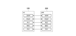
- FIG. 4 is a diagram showing a configuration of a protocol stack of a wireless interface of a user plane that handles data.
- the wireless interface protocol of the user plane includes a physical (PHY) layer, a MAC (Medium Access Control) layer, an RLC (Radio Link Control) layer, and a PDCP (Packet Data Convergence Protocol) layer. It has an SDAP (Service Data Adjustment Protocol) layer.
- PHY physical
- MAC Medium Access Control
- RLC Radio Link Control
- PDCP Packet Data Convergence Protocol
- SDAP Service Data Adjustment Protocol
- the PHY layer performs coding / decoding, modulation / demodulation, antenna mapping / demapping, and resource mapping / demapping. Data and control information are transmitted between the PHY layer of the UE 100 and the PHY layer of the gNB 200 via a physical channel.
- the MAC layer performs data priority control, retransmission processing by hybrid ARQ (HARQ), random access procedure, and the like. Data and control information are transmitted between the MAC layer of the UE 100 and the MAC layer of the gNB 200 via the transport channel.
- the MAC layer of gNB200 includes a scheduler. The scheduler determines the transport format (transport block size, modulation / coding method (MCS)) of the upper and lower links and the resource block allocated to the UE 100.
- MCS modulation / coding method
- the RLC layer transmits data to the receiving RLC layer by using the functions of the MAC layer and the PHY layer. Data and control information are transmitted between the RLC layer of the UE 100 and the RLC layer of the gNB 200 via a logical channel.
- the PDCP layer performs header compression / decompression and encryption / decryption.
- the SDAP layer maps the IP flow, which is a unit for performing QoS control by the core network, with the wireless bearer, which is a unit for performing QoS control by AS (Access Stratum).
- AS Access Stratum
- FIG. 5 is a diagram showing a configuration of a protocol stack of a wireless interface of a control plane that handles signaling (control signal).
- the protocol stack of the radio interface of the control plane has an RRC (Radio Resource Control) layer and a NAS (Non-Access Stratum) layer in place of the SDAP layer shown in FIG.
- RRC signaling for various settings is transmitted between the RRC layer of UE100 and the RRC layer of gNB200.
- the RRC layer controls logical channels, transport channels, and physical channels in response to the establishment, re-establishment, and release of radio bearers.
- RRC connection connection between the RRC of the UE 100 and the RRC of the gNB 200
- the UE 100 is in the RRC connected state.
- RRC connection no connection between the RRC of the UE 100 and the RRC of the gNB 200
- the UE 100 is in the RRC idle state.
- the connection between the RRC of the UE 100 and the RRC of the gNB 200 is suspended, the UE 100 is in the RRC inactive state.
- the NAS layer located above the RRC layer performs session management, mobility management, etc.
- NAS signaling is transmitted between the NAS layer of the UE 100 and the NAS layer of the AMF300.
- the UE 100 has an application layer and the like in addition to the wireless interface protocol.
- MBS is a service that broadcasts or multicasts data from NG-RAN10 to UE100, that is, one-to-many (PTM: Point To Multipoint) data transmission.
- PTM Point To Multipoint
- MBS may be referred to as MBMS (Multicast Broadcast and Multicast Service).
- the MBS use cases (service types) include public safety communication, mission-critical communication, V2X (Vehicle to Everything) communication, IPv4 or IPv6 multicast distribution, IPTV, group communication, software distribution, and the like.
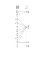
- FIG. 6 is a diagram showing the correspondence between the downlink logical channel (Logical channel) and the transport channel (Transport channel) according to the embodiment.
- the logical channels used for MBSFN transmission are MTCH (Multicast Traffic Channel) and MCCH (Multicast Control Channel), and the transport channel used for MBSFN transmission is MCH (Multicast Control Channel).
- MBSFN transmission is mainly designed for multi-cell transmission, and each cell performs synchronous transmission of the same signal (same data) in the same MBSFN subframe in an MBSFN area composed of a plurality of cells.
- SC-PTM transmission The logical channels used for SC-PTM transmission are SC-MTCH (Single Cell Multicast Traffic Channel) and SC-MCCH (Single Cell Multicast Control Channel), and the transport channels used for SC-PTM transmission are DL-SCH (Downlink). ).
- SC-PTM transmission is designed primarily for single-cell transmission and performs broadcast or multicast data transmission on a cell-by-cell basis.
- the physical channels used for SC-PTM transmission are PDCCH (Physical Downlink Control Channel) and PDSCH (Physical Downlink Control Channel), and dynamic resource allocation is possible.
- MBS may be provided using the SC-PTM transmission method.
- MBS may be provided using the MBSFN transmission method.
- MBS may be read as multicast.
- MBS may be provided by broadcast.
- MBS data means data transmitted by MBS.
- the MBS control channel refers to MCCH or SC-MCCH
- the MBS traffic channel refers to MTCH or SC-MTCH.
- the network can provide different MBS services for each MBS session.
- the MBS service is identified by at least one of TMGI (Temporary Mobile Group Identity) and a session identifier, and at least one of these identifiers is called an MBS service identifier.
- TMGI Temporary Mobile Group Identity
- Such an MBS service identifier may be referred to as an MBS session identifier or a multicast group identifier.
- the UE 100 that receives MBS can move across cells. In order for such a UE 100 to continue MBS reception, it is necessary to receive the MBS control channel (MBS control information) at least at the time of cell switching in the switching destination cell. Therefore, there is a problem that the load and power consumption of the UE 100 increase and it is difficult to promptly receive MBS data from the switching destination cell.
- MBS control information MBS control information
- control area function a function that allows MBS control information to be shared within an area range consisting of a plurality of cells.
- MBS control area range an area range consisting of a plurality of cells
- the gNB 200 transmits the MBS control information used for receiving the MBS data to the UE 100 via the MBS control channel of the own cell.
- the gNB 200 transmits to the UE 100 a control area identifier indicating an MBS control area range, which is an area range to which at least a part of the MBS control information can be applied.
- the UE 100 can grasp the MBS control area range in which the MBS control information of the current cell can be reused.
- the UE 100 stores the MBS control information and the control area identifier from the gNB 200. Then, the UE 100 receives MBS data based on the stored MBS control information within the MBS control area range indicated by the stored control area identifier. In this way, MBS data can be received by using MBS control information even across cells within the stored area range, so that the load and power consumption of the UE 100 can be suppressed, and MBS data can be quickly received from the switching destination cell. It will be easier to do.
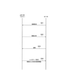
- FIG. 7 is a diagram showing the operation of the mobile communication system according to the embodiment.
- step S1 the gNB 200 that manages the cell C1 transmits MBS system information to the UE 100 via the broadcast control channel (BCCH: Broadcast Control Channel) of the cell C1.
- the transmission of MBS system information is performed by broadcasting using a predetermined RNTI (Radio Network Temporary Identifier).
- the UE 100 receives the MBS system information.
- the system information may be called SIB (System Information Block).
- MBS system information includes scheduling information necessary for receiving the MBS control channel.
- the MBS system information includes information indicating a cycle in which the contents of the MBS control channel (MBS control information) can be changed, information indicating the time interval of MBS control channel transmission in terms of the number of radio frames, and the MBS control channel being scheduled. It contains at least one of information indicating the offset of the radio frame and information indicating the subframe to which the MBS control channel is scheduled.
- the MBS system information further includes MBS control area settings.
- the MBS control area setting includes an information element (hereinafter, referred to as “applicability flag”) indicating whether or not the cell C1 can apply the control area function. If cell C1 is applicable to the control area function, the MBS system information includes the control area identifier. However, when the MBS system information exists, it is implicitly considered that the control area function can be applied, and the applicability flag does not have to exist.
- the MBS control area setting may include expiration date information (for example, valid until a certain wireless frame, valid until a certain time, valid within a certain time) indicating a period during which this MBS control area setting is valid.
- expiration date information for example, valid until a certain wireless frame, valid until a certain time, valid within a certain time
- the adjacent cells constituting the MBS control area range may change their own MBS control information. Such changes may be made by the operator's equipment, by the core network, or by signaling between gNB200.
- control area function may be restricted to be enabled only when the SFN (Single Frequency Network) is configured by a plurality of cells including the cell C1.
- SFN refers to a network in which a plurality of cells operated at the same frequency transmit the same signal at the same time.
- the UE 100 receives signals (combined signals) from the plurality of cells without identifying which cell the signal was transmitted from.
- the control area function may be enabled for the MBS control channel for configuring the SFN.
- control area identifier may be shared with the system information area identifier indicating the system information area range.
- the system information area range means an area range in which MBS system information can be reused.
- the MBS system information may include information indicating that the MBS control information conforms to the setting of the area range of the MBS system information. That is, this information is information indicating that the system information area identifier is handled as the control area identifier.
- the MBS system information may include an MBS control area setting for each MBS control channel.
- the MBS system information may include an MBS service identifier and / or an MBS control channel identifier and an MBS control area setting associated with this identifier.
- the network slice identifier associated with the MBS control channel may be included in the MBS system information.
- the UE 100 grasps the scheduling of the MBS control channel based on the MBS system information received from the gNB 200 in step S1. Further, the UE 100 stores the MBS control area setting included in the MBS system information.
- step S2 the gNB 200 transmits MBS control information via the MBS control channel by scheduling according to the MBS system information transmitted in step S1.
- the transmission of MBS control information is performed by broadcasting (or multicast) using a predetermined RNTI.
- MBS control information includes a list of scheduling information for MBS traffic channels.
- MBS traffic channels are provided for each MBS service.
- the scheduling information of the MBS traffic channel includes, for example, the MBS service identifier (for example, TMGI) and group RNTI corresponding to the MBS traffic channel, and the scheduling information (DRX (Discontinuus Reception) information) of the MBS traffic channel.
- the group RNTI has a one-to-one mapping with the MBS service identifier.
- step S3 the UE 100 stores the MBS control information received from the gNB 200 in step S2 in association with the MBS control area setting (at least, the control area identifier) included in the MBS control information received from the gNB 200 in step S1. Further, the UE 100 grasps the scheduling of the MBS traffic channel based on the MBS control information received from the gNB 200 in step S2. For example, the UE 100 grasps the scheduling of the MBS traffic channel corresponding to the MBS service of its own interest and tries to receive the MBS traffic channel.
- the MBS control area setting at least, the control area identifier
- step S4 the gNB 200 transmits MBS data via the MBS traffic channel by scheduling according to the MBS control information transmitted in step S2.
- the transmission of MBS data is performed by multicast (or broadcast) using group RNTI.
- the UE 100 receives MBS data of the MBS traffic channel corresponding to the MBS service of its interest.
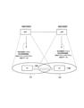
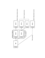
- FIG. 8 is a diagram showing an operation when the UE 100 according to the embodiment moves from the cell C1 to the cell C2.
- FIG. 8 shows an example in which cell C1 is managed by gNB200A and cell C2 is managed by gNB200B.
- the UE 100 performs handover or cell reselection when moving from cell C1 to cell C2.
- the handover means a cell switching operation of the UE 100 in the RRC connected state.
- the cell reselection is a cell switching operation of the UE 100 in the RRC idle state or the RRC inactive state.
- the UE 100 stores the MBS control information of the cell C1 in the cell C1 in association with the control area identifier (see step S3 in FIG. 7).
- the UE 100 receives the MBS system information transmitted on the broadcast control channel of the cell C2 when switching the cell from the cell C1 to the cell C2, and acquires the MBS control area setting in the MBS system information.
- the UE 100 uses the acquired control area identifier (cell C2) in the MBS control area setting. It is determined whether or not the control area identifier (control area identifier of cell C1) matches the control area identifier (control area identifier of cell C1) stored by itself. If they match, the UE 100 determines that the MBS control information (MBS control information in cell C1) stored by itself is valid, and does not receive (skip) the MBS control channel in cell C2. Then, the UE 100 attempts to receive the MBS traffic channel of the cell C2 based on the MBS control information (MBS control information of the cell C1) stored by itself, and receives the MBS data from the cell C2.
- the MBS control information MBS control information in cell C1 stored by itself
- the UE 100 reads the system information of the cell C2, and if the MBS control area range is the same, determines that the MBS control information of the cell C1 is valid in the cell C2, and receives the MBS control channel of the cell C2. Instead, it is possible to try to receive the MBS traffic channel in cell C2. This reduces the MBS reception interruption time.
- cell C1 and cell C2 are managed by separate gNB200
- cell C1 and cell C2 may be managed by the same gNB200.
- the UE 100 when the UE 100 moves from the cell C1 to the cell C2, the UE 100 acquires the control area identifier of the cell C2 before moving to the cell C2 while receiving the MBS from the cell C1. Can perform the action to be performed. Assuming that there is only one receiver for the UE 100, such an operation can be difficult. For example, the UE 100 needs to temporarily suspend the MBS reception from the cell C1 to acquire the control area identifier of the cell C2.
- the gNB 200 may transmit the adjacent cell information for specifying whether or not the cell C2 (adjacent cell) belongs to the same MBS control area range as the cell C1 to the UE 100.
- the UE 100 can grasp whether or not the cell C2 (adjacent cell) belongs to the same MBS control area range as the cell C1 based on the adjacent cell information from the cell C1. For example, the UE 100 determines whether or not MBS control information must be acquired from the adjacent cell at the time of cell switching after receiving and storing the adjacent cell information. For example, when cell C2 (adjacent cell) belongs to the same MBS control area range as cell C1, the UE 100 does not acquire (skip) the control area identifier of cell C2.
- the gNB 200 may transmit the adjacent cell information in the MBS system information via the broadcast control channel of the cell C1, or may transmit the adjacent cell information via the MBS control channel of the cell C1. ..
- the adjacent cell information includes the control area identifier of the adjacent cell (cell C2).
- the adjacent cell information may include a cell identifier and / or a frequency identifier and / or an MBS service identifier of the adjacent cell (cell C2), and a control area identifier associated with this identifier.
- the adjacent cell information may include an MBS control channel identifier and a control area identifier associated with this identifier.
- the adjacent cell information may be limited to the adjacent cell belonging to the same or different MBS control area range as the cell C1, and may include the cell identifier and / or the frequency identifier of the adjacent cell.
- the adjacent cell information may further include a system information area identifier indicating the system information area range of the adjacent cell.
- the UE 100 needs to receive the MBS control information from the cell C2.
- the gNB 200 (cell C1) transmits the MBS control information transmitted in the adjacent cell in the cell C1. do.
- the UE 100 in the cell C1 can acquire the MBS control information of the adjacent cell before moving to the adjacent cell. Therefore, when moving to the adjacent cell, MBS data can be promptly received from the adjacent cell based on the MBS control information acquired in advance.
- the gNB 200 may transmit the MBS control information of the adjacent cell via the broadcast control channel of the cell C1, or may transmit the MBS control information of the adjacent cell via the MBS control channel of the cell C1. good.
- the gNB 200 (cell C1) inputs the adjacent cell information about the adjacent cell as in the above embodiment. It may be transmitted at C1.
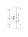
- FIG. 10 is a diagram showing the operation according to the modification example 1.
- FIG. 10 shows an example in which three cells are managed by separate gNB200s, but three cells may be managed by one gNB200.
- cell C1 and cell C2 belong to the same MBS control area range # 1, and cell C3 belongs to MBS control area range # 3.
- the gNB 200 (200A) that manages the cell C1 transmits the above-mentioned adjacent cell information in the cell C1 with respect to the cell C2.
- the UE 100 in the cell C1 grasps that the cell C2 belongs to the same MBS control area range # 1 as the cell C1 based on the adjacent cell information.
- the gNB 200 (200A) that manages the cell C1 transmits the MBS control information transmitted by the cell C3 on the MBS control channel in the cell C1.
- the gNB 200 (200A) may transmit at least a part of the above-mentioned adjacent cell information in the cell C1 in association with the MBS control information of the cell C3.
- the gNB 200 (200A) may further transmit the MBS system information transmitted by the cell C3 on the broadcast control channel in the cell C1.
- the UE 100 in the cell C1 receives and stores the MBS control information of the cell C3 from the cell C1.
- the UE 100 can quickly receive the MBS data from the cell C3 based on the stored MBS control information of the cell C3.
- the gNB 200 (200A) that manages the cell C1 may acquire MBS control information (MBS control channel setting) of the cell C3 from the gNB 200 (200C) that manages the cell C3 via the inter-base station interface.
- the gNB 200 (200A) may acquire MBS control information of cell C3 from the operator's device or core network.
- the gNB 200 (200A) transmits the acquired MBS control information of the cell C3 in the cell C1.
- the gNB 200 (200A) that manages the cell C1 may receive a change notification of the control area identifier of the cell C3 from the gNB 200 (200C) that manages the cell C3 via the inter-base station interface.
- the gNB 200 (200A) may receive a change notification of the control area identifier of the cell C3 from the operator's device or the core network.
- the gNB 200 (200A) grasps the change of the control area identifier of the cell C3 based on the received change notification.
- the gNB 200 may transmit the MBS control information of the cell C3 in the cell C1 in response to the request from the UE 100. Specifically, the UE 100 transmits a transmission request requesting MBS control information transmitted in the adjacent cell (cell C3) to the gNB 200. The gNB 200 transmits the MBS control information of the cell C3 to the UE 100 in response to the reception of this transmission request.
- the gNB 200 (200A) does not need to periodically transmit the MBS control information of the cell C3 in the cell C1, and if the MBS control information of the cell C3 is transmitted in the cell C1 when requested by the UE 100, the gNB 200 (200A) can transmit the MBS control information of the cell C3 in the cell C1. good. Therefore, the radio resource of the cell C1 can be saved.
- Random access preamble may be used as a transmission request.
- the UE 100 transmits a random access preamble using the PRACH resource selected by the UE 100 from a plurality of PRACH (Physical Random Access Channel) resources to the gNB 200 as a transmission request.
- PRACH Physical Random Access Channel
- Each of the plurality of PRACH resources is associated with at least one of an identifier of an adjacent cell, an MBS service identifier, and an identifier of an MBS control channel.
- FIG. 11 is a diagram showing another operation according to the modification example 1. In FIG. 11, the non-essential steps are shown by broken lines.
- the UE 100 may transmit a transmission request requesting transmission of MBS control information of an adjacent cell to the gNB 200.
- the UE 100 may request the gNB 200 to transmit the MBS system information of the adjacent cell in addition to the MBS control information of the adjacent cell.
- the transmission request may include MBS system information and / or the cell identifier and / or frequency identifier of the adjacent cell to be requested of the MBS control channel.
- the transmission request may include MBS system information and / or a control area identifier of the request target of the MBS control channel. If there are multiple MBS control channels in one adjacent cell, the transmit request may include the MBS control channel identifier of the requested MBS control channel.
- the UE 100 in the RRC idle state or the RRC connected state may transmit a random access preamble to the gNB 200 as a transmission request.
- the PRACH resource used for transmitting the random access preamble may be divided for each adjacent cell, for each MBS service identifier, or for each control area identifier. The information of such division is shared in advance by the UE 100 and the gNB 200, and the UE 100 selects the PRACH resource corresponding to the request target and uses it for the transmission of the random access preamble.
- the transmission request may request all MBS control information of the adjacent cell.
- the gNB 200 transmits the MBS control channel (and / or the MBS system information of the adjacent cell) of the adjacent cell based on the transmission request from the UE 100.
- This transmission may be a broadcast via the broadcast control channel or MBS control channel of cell C1, or may be a transmission by UE individual signaling (RRC message).
- Modification 2 is an embodiment mainly assuming a case where the UE 100 receives MBS from the cell C1 in the RRC idle state or the RRC inactive state.
- the UE 100 in the RRC idle state or the RRC inactive state transitions to the RRC connected state in the cell C1 when the MBS control area range to which the cell C1 belongs and the MBS control area range to which the adjacent cell belongs are different. Then, MBS control information of the adjacent cell is acquired from gNB200.
- FIG. 12 is a diagram showing an operation according to the second modification.
- step S21 the UE 100 performing MBS reception in the RRC idle state or the RRC inactive state requests a connection before reselecting the cell from the cell C1 to the adjacent cell (here, the cell C2). Send the message to cell C1.
- the transmission of the connection request message is triggered based on the radio status of cell C1 and / or cell C2.
- the threshold value to be compared with the wireless condition may be set in advance from the cell C1 to the UE 100.
- the connection request message may be an RRC Request message, which is a kind of RRC message.
- the connection request message may be an RRC Request Request message, which is a kind of RRC message.
- the gNB 200 that manages the cell C1 transmits a connection response message to the UE 100 in response to receiving the connection request message.
- the connection response message may be an RRC Setup message, which is a type of RRC message.
- the connection response message may be an RRC Resume message which is a kind of RRC message.
- the UE 100 transitioning to the RRC connected state transmits a notification message to the gNB 200.
- the UE 100 includes the MBS reception indicating that the UE 100 performs the MBS reception in the notification message.
- the UE 100 may include such MBS reception information in the connection request message in step S21.
- the MBS reception information may include the MBS service identifier of the MBS service received by the UE 100.
- the UE 100 may include measurement information indicating the measurement result for the adjacent cell (cell C2) in the notification message. Alternatively, the UE 100 may include such measurement information in the connection request message in step S21.
- the notification message may be an RRC Setup Complete message (in the case of the RRC idle state) or an RRC Reste Complete message (in the case of the RRC inactive state).
- the notification message may be an MBS interest indication message, which is a kind of RRC message.
- the notification message may be a measurement report (measurement report message) described later.
- step S24 when the UE 100 satisfies the handover criteria, the gNB 200 transmits a handover command message including the MBS control information of the adjacent cell (cell C2) to the UE 100.
- the handover command message is a kind of RRC message and is a message for instructing the UE 100 to perform a handover.
- the gNB200 (200A) that manages the cell C1 transmits a handover request to the gNB200 (200B) that manages the cell C2 prior to step S24. do.
- the handover request may include information that the UE 100 desires MBS reception.
- the gNB 200 (200B) that manages the cell C2 transmits a handover response including the MBS control information of the cell C2 to the gNB 200 (200A) that manages the cell C1 in response to the reception of the handover request.
- the gNB 200 (200A) that manages the cell C1 transmits a handover command message including the MBS control information in the handover response to the UE 100.
- the UE 100 executes the handover to the cell C2.
- the UE 100 may send a notification to the cell C2 that it wants to transition to the RRC idle state or the RRC inactive state.
- the UE 100 transitions from the RRC connected state to the RRC idle state or the RRC inactive state in the cell C2.
- the UE 100 receives MBS from the cell C1 in the RRC connected state. In this case, steps S21 and S22 in FIG. 12 are unnecessary.
- the UE 100 in the RRC connected state notifies the gNB 200 of the handover candidate cell belonging to the same MBS control area range as the cell C1 by the measurement report, so that the handover to this candidate cell can be executed. As a result, the UE 100 can promptly receive the MBS after the handover.
- the UE 100 in the RRC connected state transmits a measurement report to the gNB 200 based on whether or not the MBS control area range to which the cell C1 belongs and the MBS control area range to which the adjacent cell belongs are the same. Specifically, the UE 100 includes in the measurement report information on whether or not the MBS control area identifier is different (that is, the MBS control information needs to be reacquired) for each cell that reports the measurement result to the gNB 200 in the measurement report. ..
- the UE 100 in the RRC connected state measures each adjacent cell and confirms whether the control area identifier of the adjacent cell is the same as the control area identifier of the serving cell (cell C1).
- the MBS control area identifier of the adjacent cell may be provided to the UE 100 from the serving cell (cell C1), or may be acquired by the UE 100 reading the MBS system information of the adjacent cell.
- the UE 100 transmits a measurement report message to the gNB 200 (cell C1) when the measurement report is triggered.
- the cell identifier of the adjacent cell that includes the measurement result in the measurement report message includes information indicating that the control area identifier is the same as the cell C1 and / or the control area identifier. Information indicating that it is different from cell C1 is added. Such information may be information indicating an adjacent cell suitable for MBS reception (that is, a handover destination cell desired by itself).
- the UE 100 may include only the measurement information (cell identifier and measurement result) of the adjacent cell whose control area identifier is the same as that of the cell C1 in the measurement report message.
- the UE 100 may include only the cells whose control area identifier is the same as that of the cell C1 and whose measurement result satisfies the trigger condition of the measurement report in the measurement report message.
- the gNB 200 that manages the cell C1 determines the handover destination cell of the UE 100 based on the measurement report message from the UE 100. For example, the gNB 200 preferentially determines an adjacent cell having the same control area identifier as the cell C1 as the handover destination cell.
- the MBS control information includes a list of scheduling information for the MBS traffic channel.
- the MBS control information of each cell completely matches within the same MBS control area range.
- the MBS control information of each cell partially matches.
- the MBS control area range is set for each MBS traffic channel, with the scheduling information of the MBS traffic channel in the MBS control information as one unit.
- the control area identifier is set for each MBS control channel, whereas in the modification 3, the MBS traffic channel scheduling information (that is, MBS) in the MBS control channel (MBS control information) is set.
- MBS traffic channel scheduling information that is, MBS
- MBS control information is set.
- the scheduling information of the MBS traffic channel corresponding to this MBS service must be the same among the cells in this SFN.
- different MBS traffic channels have the same scheduling between cells.
- the gNB 200 transmits MBS control information including the scheduling information of the MBS traffic channel and the control area identifier associated with the MBS traffic channel via the MBS control channel. This makes it possible to finely set the MBS control area range subdivided for each MBS traffic channel as compared with the above-described embodiment.
- FIG. 13 is a diagram showing the operation according to the modification example 3. Here, the differences from the above-described embodiment will be mainly described.
- the gNB 200 that manages the cell C1 transmits MBS system information to the UE 100 via the broadcast control channel of the cell C1.
- the MBS system information includes scheduling information necessary for receiving the MBS control channel.
- MBS system information may include MBS control area settings as in the embodiments described above.
- the UE 100 grasps the scheduling of the MBS control channel based on the MBS system information received from the gNB 200 in step S1.
- the MBS system information includes the MBS service identifier of each MBS traffic channel in the cell C1 and the control area identifier associated with the MBS service identifier.
- the gNB 200 transmits MBS control information via the MBS control channel by scheduling according to the MBS system information transmitted in step S31.
- the MBS control information includes a list of scheduling information for the MBS traffic channel.
- the MBS traffic channel is provided for each MBS service (MBS service identifier).
- the MBS control information includes a control area identifier for each MBS traffic channel.
- the control area identifier may be associated with any one or more of the MBS service identifier, the group RNTI, and the MBS traffic channel scheduling information.
- the MBS control information may include information indicating the validity period of the control area identifier.
- the MBS control information may include information on adjacent cells (frequency identifier, cell identifier) corresponding to the same control area identifier.
- the control area identifier may be considered to be the SFN identification number.
- step S33 the UE 100 stores the MBS control information received from the gNB 200 in step S32.
- the UE 100 that receives the MBS data of a certain MBS service stores the scheduling information of the MBS traffic channel corresponding to the MBS service together with the control area identifier associated with the MBS traffic channel.
- the UE 100 grasps the scheduling of the MBS traffic channel corresponding to the MBS service of its own interest, and attempts to receive the MBS traffic channel.
- step S34 the gNB 200 transmits MBS data via the MBS traffic channel by scheduling according to the MBS control information transmitted in step S32.
- the UE 100 receives MBS data of the MBS traffic channel corresponding to the MBS service of its interest.
- the UE 100 that receives MBS in the RRC idle state or the RRC inactive state acquires the MBS system information of the cell C2 and confirms the MBS service identifier and its control area identifier included in the MBS system information.
- the control area identifier corresponding to the MBS service identifier of the MBS service that the UE 100 wants to receive matches the control area identifier of the MBS traffic channel (MBS service identifier) stored in advance, the MBS traffic channel is stored.
- MBS service identifier MBS traffic channel
- the gNB 200 that manages the cell C1 performs the handover control of the UE 100.
- the gNB200 (cell C1) is the MBS traffic channel scheduling information included in the MBS control information of the cell C2 for the UE 100 when the target cell (cell C2) is a different control area identifier for the MBS service identifier of interest to the UE 100.
- the handover command message includes the MBS traffic channel scheduling information included in the MBS control information of the cell C2.
- Modification 4 is an example for configuring SFN as described in modification 3.
- the gNB 200 transmits a message for synchronously transmitting the same MBS data among a plurality of gNB 200s to the adjacent gNB. That is, the SFN operates so that the gNB 200 is autonomously and decentralized.
- FIG. 14 is a diagram showing the operation according to the modified example 4.
- the network node 500 shown in FIG. 14 refers to a group of devices including a device of a core network and / or a device of an operator.
- the non-essential operation is shown by a broken line.
- the network node 500 sets the gNB 200A that manages the cell C1 as an anchor of a certain MBS service.
- the network node 500 may transmit (set) the identifier of each cell (each gNB) constituting the SFN of a certain MBS service to the gNB 200A. This identifier may be notified in association with the MBS service identifier.
- the gNB 200A may notify the network node 500 in advance of the presence or absence of the ability to act as an anchor.
- step S42 the gNB 200A transmits a message for requesting or setting the SFN configuration to the gNB 200B that manages the adjacent cell C2.
- the gNB 200B receives the message.
- the message may be sent and received via the inter-base station interface.
- the message may include the settings of the gNB200A itself, or may include the contents to be set by the gNB200B.
- the message contains at least one of the following information elements about SFN:
- ⁇ MBS service identifier It may further include an identifier as to whether or not it constitutes SFN.
- -Wireless resource settings Frequency resource information (eg, carrier frequency number applied to SFN, bandwidth portion (BWP), PRB information (start PRB, PRB width))
- Time resource information for example, system frame number applied to SFN, subframe number, period information (time applied to SFN (start time, end time, valid period))
- -MCS transport block size
- transport block size transport block size
- / or amount of data transmitted per subframe-System synchronization information for configuring SFN Mapping information between absolute time (GPS time, etc.) and system frame number (for example, correspondence information or offset value between a certain time and system frame number "0"), or system frame number offset value of gNB200A and gNB200B ⁇ SFN is configured.
- Data synchronization information for: Mapping information between absolute time (GPS time, etc.) and transmission data sequence number (for example, correspondence information or offset value between a certain time and transmission data sequence number "0"), or mapping information between the system frame number and transmission data sequence number. (For example, the transmission data sequence number corresponding to the system frame number "0", or the offset value). Alternatively, the amount of data to be transmitted per transmission opportunity (subframe, etc.). It should be noted that the above correspondence may be expressed by the opposite relations.
- the data synchronization information may be a system frame number corresponding to the transmission data sequence number “0”.
- Group RNTI Transport network settings-Bearer identifier-Endpoint identifier of gNB200A (IP address, GTP tunnel identifier) -Endpoint identifier of gNB200B (IP address, GTP tunnel identifier)
- step S43 gNB200B transmits a response message to the message in step S42 to gNB200A.
- the gNB 200A receives a response message.
- the response message may include the gNB200B setting (the above information element), or may simply be a notification of the completion of the setting.
- negotiation may be performed between both gNB200.
- the identifier space of the group RNTI may be divided into one that can be freely assigned by each gNB200 and one that is used in cooperation between gNB200 (only anchors can be numbered).
- the groups RNTI # 1 to 10 may be freely assigned, and the groups RNTI # 11 to 20 may be divided into those for cooperation.
- the currently assigned group RNTI may be periodically exchanged with the adjacent gNB200.
- step S44 the gNB 200A notifies the network node 500 that the settings of all the gNB 200Bs constituting the SFN have been completed.
- step S45 the network node 500 transmits the MBS data to the gNB 200A.
- the gNB 200A receives MBS data.
- step S46 the gNB 200A transfers the MBS data to the gNB 200B. In this way, the gNB 200A serves as a relay point (hub) of the user plane.
- each of gNB200A and gNB200B performs MBS transmission according to the above settings.
- change example 4 is based on SFN, but instead, MBS data may be transmitted synchronously in a cell with a different frequency.
- SFN is not configured, the same MBS data is simultaneously transmitted by a plurality of gNB200s having different frequencies.
- FIG. 14 shows an example in which MBS data is transmitted from gNB200B via gNB200A (steps S45 and S46), but the present invention is not limited to this.
- the gNB 200B may also receive MBS data directly from the network node 500.
- the endpoint identifier (IP address, GTP tunnel identifier) of the network node 500 may be notified in the message of step S42. Further, the endpoint identifier (IP address, GTP tunnel identifier) of the network node 500 may be notified in the response message in step S43.
- a program may be provided that causes a computer to execute each process performed by the UE 100 or gNB 200.
- the program may be recorded on a computer-readable medium.
- Computer-readable media can be used to install programs on a computer.
- the computer-readable medium on which the program is recorded may be a non-transient recording medium.
- the non-transient recording medium is not particularly limited, but may be, for example, a recording medium such as a CD-ROM or a DVD-ROM.
- a circuit that executes each process performed by the UE 100 or the gNB 200 may be integrated, and at least a part of the UE 100 or the gNB 200 may be configured as a semiconductor integrated circuit (chipset, SoC).
- UL feedback specifies the changes needed to improve the reliability of broadcast / multicast services.
- the level of reliability should be based on the requirements of the application / service provided.
- -PTM reception settings Receive point-to-multipoint transmissions by UEs in the RRC idle / RRC inactive state for the purpose of maintaining maximum commonality between the RRC connected state and the RRC idle / RRC inactive state. Specify the changes needed to make it possible.
- LTE eMBMS had several transmission schemes to enable multicast / broadcast services, such as MBSFN for Rel-9 and SC-PTM for Rel-13.
- MBSFN transmissions are designed primarily for multicell transmissions, and simultaneous transmissions are performed within the MBSFN area in MBSFN subframes (via PMCH).
- SC-PTM transmissions are focused on single cell transmissions and MBMSs are transmitted via PDSCH.
- FIG. 6 from the viewpoint of layer 2, MBSFN-related logical channels are mapped to MCH, while SC-PTM-related logical channels are mapped to DL-SCH.
- Findings 1 In LTE, MCCH and MTCH are mapped to MCH in the MBSFN transmission method, and SC-MCCH and SC-MTCH are mapped to DL-SCH in the SC-PTM transmission method.
- WID captures some limitations and assumptions, which help to consider what design is intended for this WI.
- the physical layer it is not expected that new numerology or physical channels will be introduced as shown below. This maps NR MBS related logical channels to DL-SCH.
- Physical layer Limits the scope of this WI to the current Rel-15 numerology, physical channels (PDCCH / PDSCH), and signals.
- Finding 2 The scope of this WI is limited to the existing numerology, physical channel (PDCCH / PDSCH). That is, it is assumed that NR MBS-related channels are mapped to DL-SCH.
- DL-SCH complies with the following restrictions and assumptions.
- Finding 3 DL-SCH (PDSCH) may be extended for multi-cell transmission in future releases.
- Proposal 1 RAN2 adopts the existing LTE SC-PTM specifications as the baseline for NR MBS design, including group scheduling mechanisms, service continuity support (such as adjacent cell information), and UE interest indications. Should be agreed.
- Proposal 2 If Proposal 1 is agreed, RAN2 will consider what will be extended in addition to the SC-PTM baseline to support the new / various use cases envisioned by NR MBS. Should be.
- LTE SC-PTM the configuration is provided by two messages: SIB20 and SC-MCCH.
- SIB 20 provides SC-MCCH scheduling information
- SC-MCCH provides SC-MTCH scheduling information including G-RNTI and TMGI, and adjacent cell information.
- the advantage of the LTE two-stage setting as shown in FIG. 15 is that the SC-MCCH scheduling is independent of the SIB20 scheduling in terms of repeat period, period, change period, and the like. In particular, frequent scheduling / updating of the SC-MCCH has been facilitated for delay-sensitive services and / or UEs that join late in the session. According to WID, one of the applications is group communication, so the same applies to NR MBS.
- Findings 4 In LTE, a two-step configuration using SIB20 and SC-MCCH is useful for different scheduling of these control channels. This is also useful for NR MBS.
- Proposal 3 RAN2 should agree on a two-step setting with different NR MBS messages, such as SC-PTM SIB20 and SC-MCCH.
- NR MBS is expected to support the various types of use cases described in WID.
- NR MBS is an application that is tolerant of delays such as IoT, from delay-sensitive applications such as mission-critical and V2X, in addition to other aspects of requirements from lossless applications such as software distribution to UDP-type streaming such as IPTV. It can be noticed that it should be properly designed for various requirements.
- control channels should be configured to meet the delay requirements from the delay-sensitive service. More signaling overhead can be incurred due to frequent scheduling.
- Purpose A of SA2 SI is about enabling general MBS services via 5GS, and the identified use cases that may benefit from this feature are public safety, mission critical, Includes, but is not limited to, V2X applications, transparent IPv4 / IPv6 multicast distribution, IPTV, software distribution over radio, group communications, and IoT applications.
- the setting channels may be separated. For example, one control channel frequently provides delay-sensitive services, and another control channel provides delay-tolerant services sparsely.
- LTE SC-PTM there is a limitation that one cell can have only one SC-MCCH. However, considering that more use cases are expected than LTE, NR MBS should remove such restrictions. If multiple SC-MCCHs are allowed in the cell, each SC-MCCH has different scheduling settings, such as repeat periods, that can be optimized for a particular service. Further consideration is needed on how to identify the SC-MCCH that the UE provides the service of interest.
- Proposal 4 RAN2 should discuss whether multiple control channels are supported in NR MBS cells, such as multiple SC-MCCHs that were not in LTE.
- NR MBS SC-MCCH ie on-demand SC-MCCH.
- SC-MCCH for delay-tolerant services is provided on demand, which can optimize signaling resource consumption.
- the network has another option to provide SC-MCCH on a regular basis, i.e., for delay-sensitive services rather than on-demand.
- Proposal 5 RAN2 should discuss options when control channels are provided on demand, such as on-demand SC-MCCH, which was not in LTE.
- the SIB provides SC-MTCH scheduling information directly, i.e., without SC-MCCH. This will provide optimizations for delay-tolerant services and / or power-sensitive UEs.
- the UE may request an SIB (on-demand), and the gNB may start providing the SIB and the corresponding service after the request from the plurality of UEs. These UEs do not need to monitor the repeatedly broadcast SC-MCCH.
- Proposal 6 RAN2 should discuss options such as SIB providing traffic channel configuration directly if multicast reception without SC-MCCH (ie, one-step configuration) is supported.
- LTE eMBMS In LTE eMBMS, there is no PDCP layer in the Uu protocol stack, as shown in FIG. 17, regardless of MBSFN or SC-PTM.
- one transmission per logical channel is allowed, i.e. only UM mode is used in the RLC layer and blind retransmission is not used in HARQ. In other words, the retransmission of lost packets relied on higher layer mechanisms in LTE eMBMS.
- Finding 6 In LTE eMBMS, the retransmission method is not supported in the AS layer.
- NR MBS seems to require a more reliable and flexible transmission method introduced as an AS function, as quoted from the following WID.
- NR MBS may require some enhancements as a function of the AS layer to improve the reliability and flexibility of multicast transmission / reception.
- HARQ MAC
- ARQ RLC
- PDCP status report
- Multicast / group cast HARQ feedback is not introduced in LTE.
- HARQ feedback of side link group cast that is, ACK / NACK or NACK-only, was supported. This is one of the possibilities of being reused and improving the performance of NR MBS.
- RAN2 may discuss the usefulness of HARQ feedback / retransmission to improve the reliability of multicast reception for idle, inactive, and connected UEs. There is.
- Proposal 7 RAN2 should discuss whether HARQ feedback / retransmission is useful for multicasting RRC idle, inactive, and connected UE NR MBS.
- Proposal 8 RAN2 should discuss whether RLC AM mode is supported for NR MBS multicast, at least for RRC connected UEs.
- FIG. 18 shows reliable receive and multicast / unicast switching enhancements.
- Support for the PDCP layer has the additional advantage that multicast bearers can be configured with split bearers and / or duplicated with unicast bearers. This has the potential of "dynamic changes in broadcast / multicast service delivery between multicast (PTM) and unicast (PTP) with default UE service continuity," as described in WID. It is also one of the mechanisms. Further studies are needed to determine whether various PDCP functions such as header compression and encryption can be supported by multicast reception.
- Proposal 9 RAN2 should discuss whether the PDCP layer is supported by a group cast of NR MBS at least in RRC connected UEs.
- the NR supports the SDAP layer to handle QoS flows within the radio bearer.
- the SDAP layer was not in eMBMS because it was not in conventional LTE.
- the SDAP layer can be assumed to be harmless to the reception of multicast data, but the need for the SDAP layer may actually depend on the assumptions / requirements of the higher layers. Therefore, RAN2 may have to wait for the progress of other WGs as to whether it is necessary.
- Finding 8 RAN2 may need to confirm with another WG whether the SDAP layer is necessary for NR MBS.
Landscapes
- Engineering & Computer Science (AREA)
- Computer Networks & Wireless Communication (AREA)
- Signal Processing (AREA)
- Multimedia (AREA)
- Computer Security & Cryptography (AREA)
- Mobile Radio Communication Systems (AREA)
Abstract
L'invention concerne un procédé de commande de communication utilisé dans un système de communication mobile qui fournit un service de diffusion/multidiffusion (MBS) d'une station de base à un équipement d'utilisateur. Selon l'invention : la station de base, qui gère une cellule, transmet des informations de commande de MBS à utiliser dans la réception de données de MBS à l'équipement d'utilisateur par le biais d'un canal de commande de MBS de la cellule ; et la station de base transmet, à l'équipement d'utilisateur, un identificateur de zone de commande indiquant une plage de zones de commande de MBS qui est une plage de zones dans laquelle au moins une portion des informations de commande de MBS peut être appliquée.
Priority Applications (2)
| Application Number | Priority Date | Filing Date | Title |
|---|---|---|---|
| JP2022541539A JP7475458B2 (ja) | 2020-08-03 | 2021-08-02 | 通信制御方法、基地局、及びユーザ装置 |
| US18/163,737 US12543022B2 (en) | 2020-08-03 | 2023-02-02 | Communication control method, base station, and user equipment |
Applications Claiming Priority (2)
| Application Number | Priority Date | Filing Date | Title |
|---|---|---|---|
| US202063060257P | 2020-08-03 | 2020-08-03 | |
| US63/060,257 | 2020-08-03 |
Related Child Applications (1)
| Application Number | Title | Priority Date | Filing Date |
|---|---|---|---|
| US18/163,737 Continuation US12543022B2 (en) | 2020-08-03 | 2023-02-02 | Communication control method, base station, and user equipment |
Publications (1)
| Publication Number | Publication Date |
|---|---|
| WO2022030452A1 true WO2022030452A1 (fr) | 2022-02-10 |
Family
ID=80118008
Family Applications (1)
| Application Number | Title | Priority Date | Filing Date |
|---|---|---|---|
| PCT/JP2021/028635 Ceased WO2022030452A1 (fr) | 2020-08-03 | 2021-08-02 | Procédé de commande de communication, station de base et équipement d'utilisateur |
Country Status (3)
| Country | Link |
|---|---|
| US (1) | US12543022B2 (fr) |
| JP (1) | JP7475458B2 (fr) |
| WO (1) | WO2022030452A1 (fr) |
Cited By (4)
| Publication number | Priority date | Publication date | Assignee | Title |
|---|---|---|---|---|
| WO2023197170A1 (fr) * | 2022-04-12 | 2023-10-19 | 北京小米移动软件有限公司 | Procédé et appareil de synchronisation de transmission, et support d'enregistrement |
| WO2024066858A1 (fr) * | 2022-09-29 | 2024-04-04 | 华为技术有限公司 | Procédé et appareil de communication |
| WO2025150264A1 (fr) * | 2024-01-09 | 2025-07-17 | シャープ株式会社 | Dispositif terminal, procédé et circuit intégré |
| WO2025150263A1 (fr) * | 2024-01-09 | 2025-07-17 | シャープ株式会社 | Dispositif terminal, procédé et circuit intégré |
Families Citing this family (3)
| Publication number | Priority date | Publication date | Assignee | Title |
|---|---|---|---|---|
| WO2022041140A1 (fr) * | 2020-08-28 | 2022-03-03 | 华为技术有限公司 | Procédé de communication et appareil de communication |
| US20240098761A1 (en) * | 2021-01-14 | 2024-03-21 | Lenovo (Beijing) Limited | Mechanism for multicast and broadcast service |
| EP4315972A4 (fr) * | 2021-05-07 | 2024-11-27 | ZTE Corporation | Procédé de transfert d'une session mbs, son système et son appareil |
Family Cites Families (26)
| Publication number | Priority date | Publication date | Assignee | Title |
|---|---|---|---|---|
| CN1285194C (zh) * | 2004-11-01 | 2006-11-15 | 华为技术有限公司 | 一种实现多播业务资源指示的方法 |
| WO2008004839A1 (fr) | 2006-07-07 | 2008-01-10 | Samsung Electronics Co., Ltd. | Procédé et système de fourniture de service dans un système de communication |
| KR20080034641A (ko) * | 2006-10-17 | 2008-04-22 | 삼성전자주식회사 | 광대역 무선접속 시스템에서 멀티캐스트 및 브로드캐스트서비스를 위한 장치 및 방법 |
| JP5047311B2 (ja) | 2007-03-19 | 2012-10-10 | エルジー エレクトロニクス インコーポレイティド | 一定のデータレートサービスのための不連続受信動作 |
| CN101340618B (zh) | 2007-07-05 | 2012-06-20 | 中国移动通信集团公司 | 资源调度方法、基站控制器、终端及资源调度系统 |
| KR101520679B1 (ko) * | 2008-02-29 | 2015-05-15 | 엘지전자 주식회사 | 멀티캐스트 방송 서비스 데이터 전송방법 |
| WO2010044600A2 (fr) * | 2008-10-15 | 2010-04-22 | Lg Electronics Inc. | Procédé et dispositif de transmission de données de commande pour service de multidiffusion |
| US8787235B2 (en) * | 2008-10-15 | 2014-07-22 | Lg Electronics Inc. | Method and apparatus for transmitting data in a wireless communication system |
| JP5573676B2 (ja) | 2008-10-31 | 2014-08-20 | 日本電気株式会社 | 移動通信システム、制御局、基地局、通信方法、プログラム |
| TWI413426B (zh) * | 2009-04-22 | 2013-10-21 | Inst Information Industry | 用於群播與廣播服務之基地台、行動裝置及其通訊方法 |
| US8364152B2 (en) * | 2009-08-26 | 2013-01-29 | Samsung Electronics Co., Ltd. | Macrocell to Femtocell and Femtocell to Femtocell handoff |
| US20110064016A1 (en) * | 2009-08-28 | 2011-03-17 | Electronics And Telecommunications Research Institute | Method of transmitting data of multicast broadcast service in mobile wireless connection system |
| US8885578B2 (en) | 2009-08-28 | 2014-11-11 | Electronics And Telecommunications Research Institute | Method of transmitting multicast broadcast service |
| US8780781B2 (en) * | 2009-08-28 | 2014-07-15 | Lg Electronics Inc. | Method and apparatus for receiving multicast and broadcast service in a broadband wireless communication system |
| US20110058511A1 (en) * | 2009-09-09 | 2011-03-10 | Electronics And Telecommunications Research Institute | Method for transmitting data of multicast broadcast service using superframe header in mobile wireless connection system |
| KR20110082473A (ko) * | 2010-01-11 | 2011-07-19 | 엘지전자 주식회사 | Mbs 데이터 전송 방법 및 기지국과, mbs 데이터 수신 방법 및 사용자기기 |
| CN102378116B (zh) * | 2010-08-17 | 2016-03-30 | 华为技术有限公司 | 节能小区的配置方法、装置及系统 |
| US9723523B2 (en) * | 2012-08-03 | 2017-08-01 | Blackberry Limited | Maintaining MBMS continuity |
| KR101910459B1 (ko) | 2012-10-08 | 2019-01-04 | 한국전자통신연구원 | 이동통신시스템에서 멀티캐스트 서비스 제공을 위한 방법 및 장치 |
| WO2015169371A1 (fr) * | 2014-05-08 | 2015-11-12 | Nokia Solutions And Networks Oy | Amélioration du rendement d'un service de diffusion multimédia |
| TWI609598B (zh) * | 2014-10-15 | 2017-12-21 | 財團法人工業技術研究院 | 基於位置資訊的通信控制方法和系統 |
| KR102106581B1 (ko) | 2016-04-20 | 2020-05-04 | 콘비다 와이어리스, 엘엘씨 | 시스템 정보 프로비저닝 및 경량 접속 시그널링 |
| KR20220123285A (ko) * | 2020-02-03 | 2022-09-06 | 엘지전자 주식회사 | 무선 통신 시스템에서 멀티캐스트-방송 서비스 영역 제어를 위한 방법 및 장치 |
| CN113938840A (zh) * | 2020-07-13 | 2022-01-14 | 华为技术有限公司 | 通信方法和通信装置 |
| EP4178263B1 (fr) * | 2020-08-03 | 2025-03-19 | Kyocera Corporation | Procédé de commande de communication |
| CN114071603A (zh) * | 2020-08-05 | 2022-02-18 | 大唐移动通信设备有限公司 | 终端移动过程中保持业务连续性的方法及装置 |
-
2021
- 2021-08-02 JP JP2022541539A patent/JP7475458B2/ja active Active
- 2021-08-02 WO PCT/JP2021/028635 patent/WO2022030452A1/fr not_active Ceased
-
2023
- 2023-02-02 US US18/163,737 patent/US12543022B2/en active Active
Non-Patent Citations (2)
| Title |
|---|
| "LTE; Evolved Universal Terrestrial Radio Access (E-UTRA); Radio Resource Control (RRC); Protocol specification (3GPP TS 36.331 version 16.1.1 Release 16)", ETSI TECHNICAL SPECIFICATION, EUROPEAN TELECOMMUNICATIONS STANDARDS INSTITUTE (ETSI), 650, ROUTE DES LUCIOLES ; F-06921 SOPHIA-ANTIPOLIS ; FRANCE, vol. 3GPP RAN, no. V16.1.1, 31 July 2020 (2020-07-31), 650, route des Lucioles ; F-06921 Sophia-Antipolis ; France , pages 1 - 1083, XP014380113 * |
| ERICSSON: "MBMS SI – Solution on MBMS service continuity", 3GPP DRAFT; S6-161553 WAS S6-161339 MBMS SI - SERVICE CONTINUITY, 3RD GENERATION PARTNERSHIP PROJECT (3GPP), MOBILE COMPETENCE CENTRE ; 650, ROUTE DES LUCIOLES ; F-06921 SOPHIA-ANTIPOLIS CEDEX ; FRANCE, vol. SA WG6, no. Reno, Nevada, USA; 20161114 - 20161118, 23 November 2016 (2016-11-23), Mobile Competence Centre ; 650, route des Lucioles ; F-06921 Sophia-Antipolis Cedex ; France , XP051201381 * |
Cited By (4)
| Publication number | Priority date | Publication date | Assignee | Title |
|---|---|---|---|---|
| WO2023197170A1 (fr) * | 2022-04-12 | 2023-10-19 | 北京小米移动软件有限公司 | Procédé et appareil de synchronisation de transmission, et support d'enregistrement |
| WO2024066858A1 (fr) * | 2022-09-29 | 2024-04-04 | 华为技术有限公司 | Procédé et appareil de communication |
| WO2025150264A1 (fr) * | 2024-01-09 | 2025-07-17 | シャープ株式会社 | Dispositif terminal, procédé et circuit intégré |
| WO2025150263A1 (fr) * | 2024-01-09 | 2025-07-17 | シャープ株式会社 | Dispositif terminal, procédé et circuit intégré |
Also Published As
| Publication number | Publication date |
|---|---|
| JPWO2022030452A1 (fr) | 2022-02-10 |
| US12543022B2 (en) | 2026-02-03 |
| JP7475458B2 (ja) | 2024-04-26 |
| US20230179963A1 (en) | 2023-06-08 |
Similar Documents
| Publication | Publication Date | Title |
|---|---|---|
| JP7518245B2 (ja) | 通信制御方法、ユーザ装置及びプロセッサ | |
| JP7475458B2 (ja) | 通信制御方法、基地局、及びユーザ装置 | |
| US20240080939A1 (en) | Communication control method and user equipment | |
| JP7834142B2 (ja) | 通信制御方法 | |
| JP7837447B2 (ja) | 通信制御方法、ユーザ装置、チップセット、プログラム及び移動通信システム | |
| JP7807403B2 (ja) | 通信制御方法、ユーザ装置、チップセット、プログラム、及び移動通信システム | |
| JP7813727B2 (ja) | 通信制御方法 | |
| JP7728405B2 (ja) | 通信制御方法、基地局、ユーザ装置及びプロセッサ | |
| US20240179798A1 (en) | Communication method | |
| US20230254668A1 (en) | Communication control method | |
| JP2026010095A (ja) | 通信制御方法、ユーザ装置、プロセッサ、プログラム、及び移動通信システム | |
| WO2022030518A1 (fr) | Procédé de commande de communication | |
| US20240237143A1 (en) | Communication method | |
| US20230262831A1 (en) | Communication control method | |
| US20240179722A1 (en) | Communication method | |
| US20250331056A1 (en) | Communication method and network apparatus |
Legal Events
| Date | Code | Title | Description |
|---|---|---|---|
| 121 | Ep: the epo has been informed by wipo that ep was designated in this application |
Ref document number: 21852355 Country of ref document: EP Kind code of ref document: A1 |
|
| ENP | Entry into the national phase |
Ref document number: 2022541539 Country of ref document: JP Kind code of ref document: A |
|
| NENP | Non-entry into the national phase |
Ref country code: DE |
|
| 122 | Ep: pct application non-entry in european phase |
Ref document number: 21852355 Country of ref document: EP Kind code of ref document: A1 |