WO2022030490A1 - ファンユニット - Google Patents
ファンユニット Download PDFInfo
- Publication number
- WO2022030490A1 WO2022030490A1 PCT/JP2021/028771 JP2021028771W WO2022030490A1 WO 2022030490 A1 WO2022030490 A1 WO 2022030490A1 JP 2021028771 W JP2021028771 W JP 2021028771W WO 2022030490 A1 WO2022030490 A1 WO 2022030490A1
- Authority
- WO
- WIPO (PCT)
- Prior art keywords
- fan
- air volume
- unit
- target value
- rotation speed
- Prior art date
- Legal status (The legal status is an assumption and is not a legal conclusion. Google has not performed a legal analysis and makes no representation as to the accuracy of the status listed.)
- Ceased
Links
Images



Classifications
-
- F—MECHANICAL ENGINEERING; LIGHTING; HEATING; WEAPONS; BLASTING
- F24—HEATING; RANGES; VENTILATING
- F24F—AIR-CONDITIONING; AIR-HUMIDIFICATION; VENTILATION; USE OF AIR CURRENTS FOR SCREENING
- F24F11/00—Control or safety arrangements
- F24F11/70—Control systems characterised by their outputs; Constructional details thereof
- F24F11/72—Control systems characterised by their outputs; Constructional details thereof for controlling the supply of treated air, e.g. its pressure
- F24F11/74—Control systems characterised by their outputs; Constructional details thereof for controlling the supply of treated air, e.g. its pressure for controlling air flow rate or air velocity
- F24F11/77—Control systems characterised by their outputs; Constructional details thereof for controlling the supply of treated air, e.g. its pressure for controlling air flow rate or air velocity by controlling the speed of ventilators
-
- F—MECHANICAL ENGINEERING; LIGHTING; HEATING; WEAPONS; BLASTING
- F04—POSITIVE - DISPLACEMENT MACHINES FOR LIQUIDS; PUMPS FOR LIQUIDS OR ELASTIC FLUIDS
- F04D—NON-POSITIVE-DISPLACEMENT PUMPS
- F04D25/00—Pumping installations or systems
- F04D25/02—Units comprising pumps and their driving means
- F04D25/08—Units comprising pumps and their driving means the working fluid being air, e.g. for ventilation
-
- F—MECHANICAL ENGINEERING; LIGHTING; HEATING; WEAPONS; BLASTING
- F04—POSITIVE - DISPLACEMENT MACHINES FOR LIQUIDS; PUMPS FOR LIQUIDS OR ELASTIC FLUIDS
- F04D—NON-POSITIVE-DISPLACEMENT PUMPS
- F04D25/00—Pumping installations or systems
- F04D25/16—Combinations of two or more pumps ; Producing two or more separate gas flows
- F04D25/166—Combinations of two or more pumps ; Producing two or more separate gas flows using fans
-
- F—MECHANICAL ENGINEERING; LIGHTING; HEATING; WEAPONS; BLASTING
- F04—POSITIVE - DISPLACEMENT MACHINES FOR LIQUIDS; PUMPS FOR LIQUIDS OR ELASTIC FLUIDS
- F04D—NON-POSITIVE-DISPLACEMENT PUMPS
- F04D27/00—Control, e.g. regulation, of pumps, pumping installations or pumping systems specially adapted for elastic fluids
- F04D27/001—Testing thereof; Determination or simulation of flow characteristics; Stall or surge detection, e.g. condition monitoring
-
- F—MECHANICAL ENGINEERING; LIGHTING; HEATING; WEAPONS; BLASTING
- F04—POSITIVE - DISPLACEMENT MACHINES FOR LIQUIDS; PUMPS FOR LIQUIDS OR ELASTIC FLUIDS
- F04D—NON-POSITIVE-DISPLACEMENT PUMPS
- F04D27/00—Control, e.g. regulation, of pumps, pumping installations or pumping systems specially adapted for elastic fluids
- F04D27/004—Control, e.g. regulation, of pumps, pumping installations or pumping systems specially adapted for elastic fluids by varying driving speed
-
- F—MECHANICAL ENGINEERING; LIGHTING; HEATING; WEAPONS; BLASTING
- F24—HEATING; RANGES; VENTILATING
- F24F—AIR-CONDITIONING; AIR-HUMIDIFICATION; VENTILATION; USE OF AIR CURRENTS FOR SCREENING
- F24F11/00—Control or safety arrangements
- F24F11/62—Control or safety arrangements characterised by the type of control or by internal processing, e.g. using fuzzy logic, adaptive control or estimation of values
- F24F11/63—Electronic processing
-
- F—MECHANICAL ENGINEERING; LIGHTING; HEATING; WEAPONS; BLASTING
- F24—HEATING; RANGES; VENTILATING
- F24F—AIR-CONDITIONING; AIR-HUMIDIFICATION; VENTILATION; USE OF AIR CURRENTS FOR SCREENING
- F24F11/00—Control or safety arrangements
- F24F11/62—Control or safety arrangements characterised by the type of control or by internal processing, e.g. using fuzzy logic, adaptive control or estimation of values
- F24F11/63—Electronic processing
- F24F11/64—Electronic processing using pre-stored data
-
- G—PHYSICS
- G05—CONTROLLING; REGULATING
- G05B—CONTROL OR REGULATING SYSTEMS IN GENERAL; FUNCTIONAL ELEMENTS OF SUCH SYSTEMS; MONITORING OR TESTING ARRANGEMENTS FOR SUCH SYSTEMS OR ELEMENTS
- G05B19/00—Program-control systems
- G05B19/02—Program-control systems electric
- G05B19/04—Program control other than numerical control, i.e. in sequence controllers or logic controllers
- G05B19/042—Program control other than numerical control, i.e. in sequence controllers or logic controllers using digital processors
-
- F—MECHANICAL ENGINEERING; LIGHTING; HEATING; WEAPONS; BLASTING
- F05—INDEXING SCHEMES RELATING TO ENGINES OR PUMPS IN VARIOUS SUBCLASSES OF CLASSES F01-F04
- F05D—INDEXING SCHEME FOR ASPECTS RELATING TO NON-POSITIVE-DISPLACEMENT MACHINES OR ENGINES, GAS-TURBINES OR JET-PROPULSION PLANTS
- F05D2260/00—Function
- F05D2260/82—Forecasts
- F05D2260/821—Parameter estimation or prediction
-
- F—MECHANICAL ENGINEERING; LIGHTING; HEATING; WEAPONS; BLASTING
- F05—INDEXING SCHEMES RELATING TO ENGINES OR PUMPS IN VARIOUS SUBCLASSES OF CLASSES F01-F04
- F05D—INDEXING SCHEME FOR ASPECTS RELATING TO NON-POSITIVE-DISPLACEMENT MACHINES OR ENGINES, GAS-TURBINES OR JET-PROPULSION PLANTS
- F05D2270/00—Control
- F05D2270/30—Control parameters, e.g. input parameters
- F05D2270/301—Pressure
- F05D2270/3015—Pressure differential pressure
-
- F—MECHANICAL ENGINEERING; LIGHTING; HEATING; WEAPONS; BLASTING
- F05—INDEXING SCHEMES RELATING TO ENGINES OR PUMPS IN VARIOUS SUBCLASSES OF CLASSES F01-F04
- F05D—INDEXING SCHEME FOR ASPECTS RELATING TO NON-POSITIVE-DISPLACEMENT MACHINES OR ENGINES, GAS-TURBINES OR JET-PROPULSION PLANTS
- F05D2270/00—Control
- F05D2270/30—Control parameters, e.g. input parameters
- F05D2270/306—Mass flow
- F05D2270/3061—Mass flow of the working fluid
-
- F—MECHANICAL ENGINEERING; LIGHTING; HEATING; WEAPONS; BLASTING
- F24—HEATING; RANGES; VENTILATING
- F24F—AIR-CONDITIONING; AIR-HUMIDIFICATION; VENTILATION; USE OF AIR CURRENTS FOR SCREENING
- F24F2110/00—Control inputs relating to air properties
- F24F2110/30—Velocity
-
- F—MECHANICAL ENGINEERING; LIGHTING; HEATING; WEAPONS; BLASTING
- F24—HEATING; RANGES; VENTILATING
- F24F—AIR-CONDITIONING; AIR-HUMIDIFICATION; VENTILATION; USE OF AIR CURRENTS FOR SCREENING
- F24F2110/00—Control inputs relating to air properties
- F24F2110/40—Pressure, e.g. wind pressure
-
- G—PHYSICS
- G05—CONTROLLING; REGULATING
- G05B—CONTROL OR REGULATING SYSTEMS IN GENERAL; FUNCTIONAL ELEMENTS OF SUCH SYSTEMS; MONITORING OR TESTING ARRANGEMENTS FOR SUCH SYSTEMS OR ELEMENTS
- G05B2219/00—Program-control systems
- G05B2219/20—Pc systems
- G05B2219/26—Pc applications
- G05B2219/2614—HVAC, heating, ventillation, climate control
-
- Y—GENERAL TAGGING OF NEW TECHNOLOGICAL DEVELOPMENTS; GENERAL TAGGING OF CROSS-SECTIONAL TECHNOLOGIES SPANNING OVER SEVERAL SECTIONS OF THE IPC; TECHNICAL SUBJECTS COVERED BY FORMER USPC CROSS-REFERENCE ART COLLECTIONS [XRACs] AND DIGESTS
- Y02—TECHNOLOGIES OR APPLICATIONS FOR MITIGATION OR ADAPTATION AGAINST CLIMATE CHANGE
- Y02B—CLIMATE CHANGE MITIGATION TECHNOLOGIES RELATED TO BUILDINGS, e.g. HOUSING, HOUSE APPLIANCES OR RELATED END-USER APPLICATIONS
- Y02B30/00—Energy efficient heating, ventilation or air conditioning [HVAC]
- Y02B30/70—Efficient control or regulation technologies, e.g. for control of refrigerant flow, motor or heating
Definitions
- an air conditioning system that controls the rotation speed of a blower fan for air conditioning in a room has become widespread.
- an air conditioning unit having a heat exchanger and an air conditioning fan, a plurality of ventilation units having a blower fan, and an air conditioning unit to a ventilation unit. It is equipped with a duct that distributes conditioned air.
- the fan unit of the first aspect is a fan unit connected to the first unit via a duct, and controls the fan, the casing, the first acquisition unit, the second acquisition unit, and the third acquisition unit. It has a department.
- the fan supplies air to the target space.
- the casing is formed with a suction port and an outlet, and accommodates a fan.
- the first acquisition unit acquires the rotation speed of the fan motor that drives the fan.
- the second acquisition unit acquires information on at least one of the fan air volume, wind speed, and front-rear differential pressure.
- the front-rear differential pressure is the pressure difference between the suction port and the air outlet of the casing.
- the third acquisition unit acquires the air volume target value or the wind speed target value of the fan.
- the control unit controls the rotation speed of the fan motor to the rotation speed target value corresponding to the fan air volume target value or the wind speed target value.
- the control unit uses the first function or the second function in which the rotation speed of the fan motor, the air volume, the wind speed or the front-rear differential pressure of the fan, and the air volume target value or the wind speed target value of the fan are variables, and the first function is used. Calculates the rotation speed target value of the fan motor by the second function, and calculates the rotation speed change amount from the rotation speed of the fan motor to the rotation speed target value by the second function.
- the fan unit of the second viewpoint is a fan unit of the first viewpoint
- the first function and the second function are the rotation speed of the fan motor, the air volume or speed of the fan, the front-rear differential pressure, and the air volume target of the fan.
- the value or the wind speed target value is used as a variable.
- the rotation speed of the fan motor, the air volume or speed of the fan, and the front-rear differential pressure are parameters having a relationship in which the remaining one value is derived from two of them.
- test man-hours in advance increase and it is necessary to adjust the static pressure while performing a trial run when connecting the duct. there were.
- the duct resistance also changes if the wind speed changes even if the duct length is constant, so the correlation between the fan motor rotation speed and the duct resistance is measured in advance. That is extremely difficult.
- the change in duct resistance appears as a change in static pressure before and after the fan, so the change in duct resistance can be substituted by the change in front-rear differential pressure. It has been confirmed by the applicant's experiment that the correlation between the rotation speed of the fan motor and the front-rear differential pressure can be measured relatively easily using a wind speed sensor.
- this fan unit by acquiring information on the air volume, wind speed, or differential pressure between the front and rear, it is possible to calculate the rotation speed target value or the rotation speed change amount by a predetermined function using a variable that adds the rotation speed and the target air volume value. It will be possible. As a result, the number of pre-test man-hours is reduced, and the trial run at the time of duct connection becomes unnecessary.
- the fan unit of the third viewpoint is the fan unit of the second viewpoint, and the data of the air volume or the wind speed of the fan when the first function and the second function change the rotation speed of the fan motor in the front-rear differential pressure. It is decided based on.
- the correlation between the rotation speed N and the wind speed V can be obtained.
- the coefficient and the constant term can be calculated for each front-rear differential pressure based on the calculation formula obtained from the result of the wind speed measurement test performed by changing the rotation speed of the fan motor in advance.
- the fan unit of the fourth viewpoint is any one of the fan units from the first viewpoint to the third viewpoint, and the larger the front-rear differential pressure of the control unit, the smaller the amount of change of the fan motor per unit air volume. To control.
- the fan unit of the fifth viewpoint is any one of the fan units from the first viewpoint to the fourth viewpoint, and the control unit can switch between the first program and the second program.
- the first program uses the first function to calculate the rotation speed target value of the fan motor.
- the second program uses the second function to calculate the amount of change in the rotation speed of the fan motor.
- the first program calculates the rotation speed target value of the fan motor
- the second program calculates the rotation speed change amount of the fan motor.
- the first program and the second program can be switched.
- either the first function or the second function may be used.
- the rotation speed can be controlled while calculating the rotation speed change amount by the second function without using the first function.
- the fan unit of the sixth viewpoint is the fan unit of the fifth viewpoint, and the third acquisition unit acquires the air volume target value or the wind speed target value a plurality of times.
- the control unit executes the first program to calculate the rotation speed target value of the fan motor. Further, the control unit switches to the second program after the third acquisition unit acquires the air volume target value or the wind speed target value until the next acquisition, and calculates the amount of change in the rotation speed of the fan motor by the second function. do.
- control unit In the case of a configuration in which the control unit acquires the air volume target value at predetermined time intervals regardless of whether or not the air volume target value is instructed, the control unit switches to the second program until the next acquisition, and the second function. It is sufficient to calculate the amount of change in the rotation speed of the fan motor.
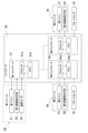
- the conceptual diagram which shows the structure of the air supply system which mounted the fan unit which concerns on one Embodiment of this disclosure.
- a block diagram for explaining the configuration of the controller. A graph showing the relationship between air volume and duct resistance with the duct length as a parameter. The graph which shows the result of having measured the amount of change of the air volume when the rotation speed of a fan motor was changed by 1 [r / m] by changing the front-rear differential pressure of the 2nd unit.
- a graph showing the relationship between the air volume and the rotation speed of the fan motor with the front-rear differential pressure as a parameter.
- FIG. 1 is a configuration diagram of an air supply system 10 equipped with a fan unit according to an embodiment of the present disclosure.
- the air supply system 10 includes a first unit 20, a plurality of second units 30, a duct 40, and a controller 50.
- the fan unit is referred to as a second unit for convenience of explanation.
- the first unit 20 has a first fan 21.
- Each second unit 30 has a second fan 31.
- Each second fan 31 supplies air from the second unit 30 to the target space 100.
- the target space 100 is, for example, a room in a building.
- a room is, for example, a space in which the movement of air is restricted by floors, ceilings and walls.
- a plurality of second units 30 are arranged for one or a plurality of target spaces 100.
- FIG. 1 shows an example in which an air supply system 10 including two second units 30 is arranged with respect to one target space 100 as a typical example of an air supply system 10 including a plurality of second units 30. It is shown.
- the number of the second units 30 may be 3 or more, and is appropriately set.
- the target space 100 in which the second unit 30 is arranged may be two or more.
- the duct 40 distributes the first air SA sent from the first unit 20 by the first fan 21 to a plurality of second units 30.
- the duct 40 includes a main pipe 41 and a branch pipe 42 branched from the main pipe 41.
- FIG. 1 shows a case where the main pipe 41 is arranged outside the first unit 20, the main pipe 41 may be arranged inside the first unit 20 and may be arranged in the first unit 20. It may be arranged so as to extend from the inside to the outside of the first unit 20.
- FIG. 1 shows an example in which the inlet 41a of the main pipe 41 is connected to the first unit 20.
- the first fan 21 is arranged in the first unit 20. Here, all the air blown out from the first fan 21 is configured to flow into the duct 40.
- the outlet 41b of the main pipe 41 of the duct 40 is connected to the inlet 42a of the branch pipe 42.
- a configuration for branching from the main pipe 41 to the branch pipe 42 a configuration using a branch chamber may be used.
- the casing 33 of the second unit 30 has a suction port 33a and an outlet 33b, and the plurality of outlets 42b of the branch pipe 42 are connected to the suction ports 33a of the plurality of second units 30.
- Each second unit 30 and the target space 100 are connected by a ventilation passage 81.
- the inlet 81a of the ventilation passage 81 is connected to the outlet 33b of the second unit 30.
- Each second fan 31 generates an air flow from the outlet 42b of the duct 40 toward the inlet 81a of the ventilation passage 81 in the second unit 30. Therefore, each second fan 31 sucks the first air SA from the outlet 42b of the branch pipe 42.
- Each second fan 31 can change the front-rear differential pressure, which is the pressure difference between the suction port 33a and the outlet 33b of each second unit 30, by changing the rotation speed of the motor. Assuming that the static pressure of the duct 40 is constant, each second fan 31 can increase the front-rear differential pressure of each second unit 30 by increasing the rotation speed.
- the controller 50 includes a first controller 51 and a plurality of second controllers 52.
- the first controller 51 and the plurality of second controllers 52 are connected to each other.
- the first controller 51 controls the rotation speed of the first fan 21. As the rotation speed of the first fan 21 increases, the amount of air blown by the first fan 21 increases.
- One second controller 52 is provided for one second unit 30. Each second controller 52 controls the air volume of the corresponding second fan 31. Each second controller 52 stores the air volume target value received from the first controller 51.
- Each second controller 52 increases the rotation speed of the second fan 31 if the supply air volume is insufficient with respect to the air volume target value. On the contrary, if the supply air amount is excessive with respect to the air volume target value, the second controller 52 reduces the rotation speed of the second fan 31.
- the controller 50 obtains information on the amount of air supplied to the target space 100 by the plurality of second fans 31.
- the air amount information is, for example, the required supply air amount to be supplied to the target space 100 per second or per minute.
- Each second controller 52 outputs information on the amount of air to the first controller 51. Based on the obtained information on the amount of air, the output to be requested by the first fan 21 is determined.
- First unit 20 includes a first fan 21, a heat exchanger 22, a first air volume detecting means 23, a temperature sensor 24, and a water volume adjusting valve 25.
- Heat exchanger 22 For example, cold water or hot water is supplied to the heat exchanger 22 as a heat medium from the heat source unit 60.
- the heat medium supplied to the heat exchanger 22 may be something other than cold water or hot water, for example brine.
- First air volume detecting means 23 For the first air volume detecting means 23, for example, an air volume sensor, a wind speed sensor, or a differential pressure sensor can be used. In the present embodiment, the first air volume detecting means 23 detects the air volume blown by the first fan 21.
- the first air volume detecting means 23 is connected to the first controller 51.
- the air volume value detected by the first air volume detecting means 23 is transmitted from the first air volume detecting means 23 to the first controller 51.
- the air volume detected by the first air volume detecting means 23 is the air volume flowing through the main pipe 41 of the duct 40, and is also the total amount of the supply air air volume supplied from the plurality of second units 30 to the target space 100.
- Temperature sensor 24 detects the temperature of the first air SA sent from the first fan 21 to the duct 40.
- the temperature sensor 24 is connected to the first controller 51.
- the value detected by the temperature sensor 24 is input to the first controller 51.
- (2-1-4) Water volume adjusting valve 25 The first unit 20 is connected to the target space 100 via the ventilation passage 82.
- the second air RA returned from the target space 100 through the ventilation passage 82 is sent out to the duct 40 through the heat exchanger 22 by the first fan 21.
- This second air RA returned from the target space 100 is the air that was in the target space 100.
- the returned second air RA exchanges heat with the cold water or hot water flowing through the heat exchanger 22 to become conditioned air.
- the amount of heat given to the first air SA that exchanges heat with the heat exchanger 22 and is sent to the duct 40 is adjusted by the water amount adjusting valve 25.
- the opening degree of the water amount adjusting valve 25 is controlled by the first controller 51. As the opening degree of the water amount adjusting valve 25 increases, the amount of water flowing through the heat exchanger 22 increases, and the amount of heat exchanged between the heat exchanger 22 and the first air SA per unit time increases. On the contrary, when the opening degree of the water amount adjusting valve 25 becomes small, the amount of water flowing through the heat exchanger 22 decreases, and the amount of heat exchanged between the heat exchanger 22 and the first air SA per unit time decreases.
- the second unit 30 has a second fan 31, a fan motor 31b for rotating the second fan 31, and a second air volume detecting means 32.
- Each fan motor 31b is connected to one corresponding second controller 52, and the rotation speed is sent from the fan motor 31b to the second controller 52.
- Each second air volume detecting means 32 is connected to one corresponding second controller 52.
- the second air volume detecting means 32 for example, an air volume sensor, a wind speed sensor, or a differential pressure sensor can be used. In the present embodiment, the second air volume detecting means 32 detects the air volume blown by the second fan 31.
- the air volume value detected by the second air volume detecting means 32 is input to the second controller 52.
- the air volume detected by the second air volume detecting means 32 is the air volume flowing through the ventilation passage 81, and is also the air supply air volume supplied from each of the second units 30 to the target space 100.
- Remote sensor 70 The plurality of remote sensors 70 have the function of a temperature sensor. Each remote sensor 70 is configured to transmit data indicating the temperature of the second air RA in the target space 100 to the corresponding second controller 52.
- FIG. 2 is a block diagram for explaining the configuration of the controller 50.
- the controller 50 includes a first controller 51 and a plurality of second controllers 52.
- the first controller 51 and the plurality of second controllers 52 are connected to each other.
- the first controller 51 includes a processor 51a and a memory 51b.
- the processor 51a reads the air volume control program of the first fan 21 stored in the memory 51b, and outputs a command required for the first fan 21 and each second controller 52.
- the memory 51b stores the detection values of the first air volume detecting means 23 and the temperature sensor 24 at any time in addition to the air volume control program of the first fan 21.
- the processor 51a reads the detection values of the first air volume detecting means 23 and the temperature sensor 24 stored in the memory 51b, and calculates the air volume target value (total amount of the target air volume to be supplied to the target space 100) of the first fan 21. ..
- the second controller 52 includes a processor 52a and a memory 52b.
- the processor 52a reads the air volume control program of the second fan 31 stored in the memory 52b, and outputs a command required for the second fan 31.
- the memory 52b stores the air volume target value output from the first controller 51 and the detection value of the second air volume detecting means 32 at any time, in addition to the air volume control program of the second fan 31.
- the processor 52a reads the air volume target value stored in the memory 52b and the detection value of the second air volume detecting means 32, and calculates the rotation speed target value of the second fan 31.
- Each second controller 52 receives a temperature measurement value of the target space 100 from a remote sensor 70 connected to each second controller 52. Each second controller 52 holds data indicating the set temperature as a temperature set value.
- Each second controller 52 transmits a temperature set value and a temperature measured value to the first controller 51.
- the first controller 51 determines the air volume target value of each second unit 30 based on the temperature set value and the temperature measured value.
- the first controller 51 transmits the value of the air volume target value to each second controller 52.
- the first controller 51 determines the air volume target value of the first fan 21 according to the total amount of the target air volume to be supplied to the target space 100, and transmits the air volume target value to each of the second controllers 52.
- the rotation speed of the second fan 31 is adjusted by the corresponding second controller 52.
- the rotation speeds of the plurality of second fans 31 are adjusted independently of each other.
- Each second controller 52 controls the rotation speed of each second fan 31 in order to match the supplied air volume with the air volume target value.
- the plurality of second controllers 52 control the rotation speeds of the plurality of second fans 31 independently of each other. If the air volume detected by the second air volume detecting means 32 is smaller than the air volume target value, each second controller 52 increases the rotation speed of each second fan 31. If the air volume detected by the second air volume detecting means 32 is larger than the air volume target value, each second controller 52 reduces the rotation speed of each second fan 31.
- Duct resistance (4-1) Duct resistance characteristics
- the length of the duct 40 that connects the first unit 20 and the second unit 30 differs depending on the position of the outlet of the second unit 30, and the first It also depends on the property where the 1st unit 20 and the 2nd unit 30 are installed.
- duct resistance resistance between the air flowing in the duct 40 and the inner surface of the duct 40, and the static pressure of the air flowing in the duct 40 is reduced by friction.
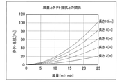
- FIG. 3 is a graph showing the relationship between the air volume and the duct resistance with the duct length as a parameter.
- the duct resistance changes non-linearly with respect to the air volume of the air flowing in the duct 40. Therefore, the air volume is not proportional to the rotation speed of the fan. Therefore, the number of revolutions that achieves the target air volume value cannot be calculated proportionally.
- FIG. 4 is a graph showing the results of measuring the amount of change in air volume when the rotation speed of the fan motor 31b is changed by 1 [r / m] by changing the front-rear differential pressure of the second unit 30.
- the rotation speed of the fan motor 31b before the change is 100 [r / m].
- the front-rear differential pressure of the second unit 30 changes the air volume of the other second unit 30. It is also affected by the air discharge pressure of the first unit 20.
- the second unit 30 also needs an air volume maintaining function in consideration of the change in the front-rear differential pressure.
- Air volume control As described above, the air volume control of the second unit 30 requires a function to maintain the air volume in consideration of the duct resistance, the air volume of the other second unit 30, and the air discharge pressure of the first unit 20. I understand that.
- the duct length changes depending on the property where the first unit 20 and the second unit 30 are installed, or the installation position of the second unit 30, and the duct resistance also varies depending on the duct length and the air volume of the air flowing in the duct. .. Therefore, it is difficult to digitize the relationship between the rotation speed of the fan motor 31b and the air volume by the conventional test run adjustment.
- the applicant pays attention to the fact that the change in the duct resistance appears as the front-rear differential pressure, acquires the information of the air volume, the wind speed, or the front-rear differential pressure of the second unit 30, and obtains the rotation speed and the target of the fan motor 31b. It has been found that the rotation speed target value of the fan motor 31b or the rotation speed change amount of the fan motor 31b is calculated by a function using a variable to which the air volume value is added.
- FIG. 7 is a graph showing the relationship between the wind speed V and the rotation speed N of the fan motor 31b with the front-rear differential pressure ⁇ P as a parameter.
- the rotation speed N of the fan motor 31b can be expressed by a linear expression of the wind speed V using the coefficient a and the constant term b.
- N a ⁇ V + b [1]
- the equation [1] can be derived by carrying out a test for obtaining a value of at least 3 points.
- FIG. 8 is a graph showing the relationship between the front-rear differential pressure ⁇ P derived from FIG. 7 and the coefficient a and the constant term b.
- Equation [5] means that the front-rear differential pressure ⁇ P can be calculated by measuring the wind speed V when the fan motor 31b of the second fan 31 is operated at the rotation speed N.
- the rotation speed N of the fan motor 31b, the wind speed V or the air volume Q of the second fan 31, and the front-rear differential pressure ⁇ P are parameters having a relationship in which the remaining one value is derived from two of them. Is.
- FIG. 9 is a graph showing the relationship between the air volume and the rotation speed of the fan motor 31b with the front-rear differential pressure ⁇ P as a parameter.
- the change in duct resistance appears as a change in the front-rear differential pressure ⁇ P.
- the rotation speed of the fan motor 31b for maintaining the air volume of 10 [m 3 / min] at the front-rear differential pressure of 50 [Pa] is 920 [r / m]. If the duct resistance is constant regardless of the air volume, when changing the air volume to 15 [m 3 / min], the rotation speed may be simply set to 1100 [r / m].
- the duct resistance changes by changing the air volume.
- the front-rear differential pressure increases to 109.9 [Pa] due to the change in duct resistance.
- the rotation speed of the fan motor 31b it is necessary to maintain the rotation speed of the fan motor 31b at 1348 [r / m].
- the second controller 52 calculates the rotation speed target value of the fan motor 31b of the second fan 31 using the first function. do.
- FIG. 10 is a graph showing the relationship between the wind speed and the rotation speed of the fan motor 31b.
- the rotation speed of the fan motor 31b required to maintain the wind speed target value Vy at a front-rear differential pressure of 50 [Pa] is 980 [r / m].
- the rotation speed change amount ⁇ N of the fan motor 31b is obtained from the equations [2] and [4].
- ⁇ N a ⁇ (Vy ⁇ Vx) [9] Will be.
- this equation [9] is referred to as a second function.
- the scene where the second function is used is when the rotation speed change amount is calculated when the rotation speed of the fan motor 31b needs to be changed due to the fluctuation of the front-rear differential pressure ⁇ P, although the air volume target value Qy is not changed. ..
- FIG. 11 is a flowchart of air volume control. Hereinafter, air volume control will be described with reference to FIG. 11.
- Step S1 the second controller 52 determines in step S1 whether or not the air volume target value Qy has been received from the first controller 51. The second controller 52 proceeds to step S2 when the air volume target value Qy is received. Further, the second controller 52 proceeds to step S6 when the air volume target value Qy is not received.
- Step S2 the second controller 52 calculates the wind speed target value Vy that realizes the air volume target value Qy in step S2.
- Step S3 the second controller 52 updates the wind speed target value Vy to the value calculated in step S2 in step S3.
- Step S4 the second controller 52 calculates the rotation speed target value Ny of the fan motor 31b that realizes the wind speed target value Vy updated in step S3 by using the first function.
- step S5 the second controller 52 updates the rotation speed target value of the fan motor 31b to the value Ny calculated in step S4. After updating the rotation speed target value to Ny, the second controller 52 controls so that the rotation speed of the fan motor 31b becomes the target value.
- Step S6 the second controller 52 acquires the detected value of the second air volume detecting means 32 as the current wind speed value Vx.
- Step S7 the second controller 52 calculates the difference between the wind speed target value Vy and the current wind speed value Vx in step S7.
- Step S8 the second controller 52 calculates the front-rear differential pressure ⁇ P in step S8.
- Step S9 the second controller 52 calculates the coefficient a as a control parameter in step S9.
- Step S10 the second controller 52 rotates by applying the difference between the wind speed target value Vy calculated in step S7 and the current wind speed value Vx and the coefficient a calculated in step S9 to the second function. Calculate the number change amount ⁇ N.
- step S11 the second controller 52 calculates the rotation speed target value Ny based on the rotation speed change amount ⁇ N calculated in step S10.
- step S12 the second controller 52 updates the rotation speed to the rotation speed target value Ny calculated in step S11. Then, the second controller 52 returns to step S1.
- step S1 to step S5 the first program from step S1 to step S5 is executed, and when the first controller 51 does not instruct the air volume target value, steps S6 to step are executed.
- the second program up to S12 is executed.
- the first program is a program that calculates the rotation speed target value using the first function
- the second program is a program that calculates the rotation speed change amount using the second function.
- the rotation speed target value Ny can be calculated using the second function and the second controller 52 can switch between the first program and the second program, the second unit 30 has a new air volume. Even when the target value Qy or the wind velocity target value Vy is acquired, the rotation speed can be controlled while calculating the rotation speed change amount ⁇ N by the second function without using the first function.
- the second controller 52 has the rotation speed Nx of the fan motor 31b of the second fan 31, the air volume Qx of the second fan 31, the wind speed Vx or the front-rear differential pressure ⁇ Px, and the air volume target value Qy or the wind speed target of the second fan 31.
- the rotation number target value Ny is calculated.
- the first function and the second function are the rotation speed Nx of the fan motor 31b of the second fan 31, the air volume Qx or the wind speed Vx of the second fan 31, the front-rear differential pressure ⁇ P, and the air volume target value of the second fan 31.
- the variable is Qy or the wind speed target value Vy.
- the rotation speed of the fan motor 31b, the air volume or speed of the fan, and the front-rear differential pressure are parameters having a relationship in which the remaining one value is derived from two of them.
- the second unit 30 it is possible to calculate the rotation speed target value Ny or the rotation speed change amount ⁇ N by the first function and the second function, the pre-test man-hours are reduced, and the test run at the time of duct connection is performed. It becomes unnecessary.
- the coefficient and the constant can be calculated for each front-rear differential pressure based on the calculation formula obtained from the result of the wind speed measurement test performed by changing the rotation speed of the fan motor 31b in advance.
- the second controller 52 controls so that the amount of change in the rotation speed of the fan motor 31b per unit air volume becomes smaller as the front-rear differential pressure ⁇ P becomes larger.
- the second controller 52 uses the first function to calculate the rotation speed target value Ny of the fan motor 31b, and the second function to calculate the rotation speed change amount ⁇ N of the fan motor 31b. It is possible to switch between the program and the program. Further, in the second unit 30, when a new air volume target value Qy or wind speed target value Vy is acquired, either the first function or the second function may be used.
- the second controller 52 When the second controller 52 acquires the air volume target value Qy or the wind speed target value Vy from the first controller 51, the second controller 52 executes the first program to calculate the rotation speed target value Ny of the fan motor 31b. Further, the second controller 52 switches to the second program after acquiring the air volume target value Qy or the wind speed target value Vy from the first controller 51 until the next acquisition, and the rotation of the fan motor 31b by the second function. Calculate the number change amount ⁇ N.
- the first unit 20 has the first fan 21, but the first unit 20 does not necessarily require the first fan 21.
- the air volume control of the present disclosure is also applicable to a second unit connected to a first unit having no fan via a duct.
- FIG. 12 is a configuration diagram of an air supply system 110 equipped with a fan unit according to the first modification.
- the air supply system 110 is arranged behind the ceiling on one floor of the building BL to ventilate the room.
- the air supply system 110 includes a first unit 120 as an air processing unit, a second unit 130 as an air supply fan unit, and a third unit 135 as an exhaust fan unit.
- the air supply system 110 further includes an outside air duct 150, an air supply duct 160, a return air duct 170, and an exhaust duct 180.
- the outside air duct 150, the air supply duct 160, the return air duct 170, and the exhaust duct 180 are connected to the first unit 120.
- the outside air duct 150 constitutes an air flow path connecting the opening 104 leading to the outside of the building BL to the first unit 120.
- the air supply duct 160 constitutes an air flow path that connects the first unit 120 to the outlet 102 provided in the room.
- the return air duct 170 constitutes an air flow path that connects the suction port 103 provided in the room to the first unit 120.
- the exhaust duct 180 constitutes an air flow path leading from the first unit 120 to the opening 105 leading to the outside of the building BL.
- the air supply duct 160 is branched from one main duct 161 to a plurality of branch ducts 162 by the branch chamber 191.
- the return air duct 170 is branched from one main duct 171 to a plurality of branch ducts 172 by the branch chamber 192.
- the first unit 120 removes dust in the air, changes the temperature of the air, changes the humidity of the air, and removes predetermined chemical components and predetermined pathogens in the air from the air passing through the unit.
- the second unit 130 is connected to each air supply duct 160.
- the third unit 135 is connected to each return air duct 170.
- the second unit 130 and the third unit 135 generate the air flow in the first unit 120.
- the change in the front-rear differential pressure of the second unit 130 is mainly caused by the change in the air volume of the fan of the other second unit 130.
- the change in the front-rear differential pressure of the third unit 135 is mainly caused by the change in the air volume of the fan of the other third unit 135.
- front-rear differential pressure is introduced as a variable of the calculation formula of the rotation speed target value, so that the change of the duct resistance that changes every moment is used for the calculation of the air volume target value. It can be reflected, and the response time of the output value (air volume) with respect to the input value (rotation speed) can be shortened.
- FIG. 13 is a configuration diagram of an air supply system 210 equipped with a fan unit according to the second modified example.
- the air supply system 210 is arranged behind the ceiling on one floor of the building BL.
- the difference between the air supply system 210 and the air supply system 10 of FIG. 1 is that the first unit does not have the first fan, and the other configurations are the same as those of the air supply system 10 of FIG. .. Therefore, the same components as those of the air supply system 10 of FIG. 1 are designated by the same reference numerals, and the description thereof will be omitted.
- the user-side heat exchanger 22 of the first unit 220 is supplied with heat energy required for heat exchange from the heat source unit 60.
- the first unit 220 generates conditioned air by heat exchange in the utilization side heat exchanger 22.
- a duct 40 is connected to the first unit 220.
- the duct 40 includes a main pipe 41 and a branch pipe 42.
- One end of the main pipe 41 is connected to the first unit 220.
- the other end of the main pipe 41 is branched and connected to a plurality of branch pipes 42.
- One second unit 30 is connected to the end of one branch pipe 42.
- Each second unit 30 has a second fan 31. By rotating the second fan 31, the conditioned air generated by the first unit 20 is sucked into the second unit 30 through the duct 40, and then supplied to the target space 100.
- the fan motor 31a of each second fan 31 is configured so that the rotation speed can be changed individually. By individually changing the rotation speed of each fan motor 31a, the amount of supply air of each second unit 30 is individually changed.
- the second unit 30 since the first unit 220 does not have a fan, the second unit 30 generates an air flow in the first unit 220.
- the change in the front-rear differential pressure of the second unit 30 is mainly caused by the change in the air volume of the second fan 31 of the other second unit 30, but "front-back differential pressure" is introduced as a variable of the calculation formula of the rotation speed target value. Therefore, it is possible to reflect the ever-changing change in duct resistance in the calculation of the air volume target value, and it is possible to shorten the response time of the output value (air volume) with respect to the input value (rotation speed).
- the front-rear differential pressure is calculated based on the wind speed or the air volume value acquired from the second air volume detecting means 32.
- pressure sensors may be arranged at the suction port and the air outlet of the second unit, the front-rear differential pressure value may be calculated from the sensor value, and the wind speed value may be obtained from the front-rear differential pressure and the rotation speed.
- FIG. 7 shows the change in the wind speed of the fan when the rotation speed of the fan motor is changed at the five front-rear differential pressures. This is used as data for deriving the relational expression of rotation speed, wind speed, and front-rear differential pressure, but it does not necessarily require data at five front-rear differential pressures, and data at at least three front-rear differential pressures are available. If so, the relational expression can be derived.
Landscapes
- Engineering & Computer Science (AREA)
- General Engineering & Computer Science (AREA)
- Mechanical Engineering (AREA)
- Physics & Mathematics (AREA)
- Chemical & Material Sciences (AREA)
- Signal Processing (AREA)
- Combustion & Propulsion (AREA)
- Mathematical Physics (AREA)
- Fuzzy Systems (AREA)
- Fluid Mechanics (AREA)
- Automation & Control Theory (AREA)
- General Physics & Mathematics (AREA)
- Air Conditioning Control Device (AREA)
- Control Of Positive-Displacement Pumps (AREA)
Abstract
ファンユニットにおいて、事前の試験工数の低減、およびダクト接続時の試運転不要化を実現する。第2コントローラ(52)は、第2ファン(31)のファンモータ(31b)の回転数(Nx)と、第2ファン(31)の風量(Qx)、風速(Vx)または前後差圧(△Px)と、第2ファン(31)の風量目標値(Qy)または風速目標値(Vy)を取得して、第1関数:Ny=(Qy/Qx)2×△Px×{m×(Qy/Qx)×Vx+p}+n×(Qy/Qx)×Vx+qを用いてファンモータ31bの回転数目標値Nyを演算する。また、前後差圧(△P)が変動して風速がVtからVまで低下した場合には、第2関数:△N=a×(Vt-V)を用いて回転数目標値への回転数変更量(△N)を演算する。
Description
熱交換した空気を送風するファンを備えるファンユニットに関する。
従来、部屋の空気調和のために送風ファンの回転数を制御する空気調和システムが広く普及している。例えば、特許文献1(特開平10-253132号公報)に記載の空気調和システムでは、熱交換器および空調用ファンを有する空調ユニットと、送風ファンを有する複数の通気ユニットと、空調ユニットから通気ユニットに調和空気を分配するダクトとを備えている。
上記のような空気調和システムでは、風量目標値を実現するための回転数を決定するために、従来のような電流値制御を行った場合、事前の試験工数が多くなり、さらにダクト接続時に試運転を行いながら静圧を調整する必要があった。
それゆえ、事前の試験工数の低減、およびダクト接続時の試運転不要化、という課題が存在する。
第1観点のファンユニットは、第1ユニットにダクトを介して接続されるファンユニットであって、ファンと、ケーシングと、第1取得部と、第2取得部と、第3取得部と、制御部とを備えている。ファンは、空気を対象空間に供給する。ケーシングは、吸込口および吹出口が形成され、ファンを収容する。第1取得部は、ファンを駆動するファンモータの回転数を取得する。第2取得部は、ファンの風量、風速および前後差圧のうち少なくとも1つの情報を取得する。前後差圧とは、ケーシングの吸込口と吹出口との空気の圧力差である。第3取得部は、ファンの風量目標値または風速目標値を取得する。制御部は、ファンモータの回転数を、ファンの風量目標値または風速目標値に対応する回転数目標値へ制御する。制御部は、ファンモータの回転数と、ファンの風量、風速または前後差圧と、ファンの風量目標値または風速目標値とを変数とする第1関数または第2関数を用いて、第1関数によりファンモータの回転数目標値を演算し、第2関数によりファンモータの回転数から回転数目標値への回転数変更量を演算する。
このファンユニットでは、回転数目標値の演算に、従来では考慮されていなかった「前後差圧(△P)」を変数として導入した結果、従来の制御に比べて必要な風量を精度よく実現することができる。
第2観点のファンユニットは、第1観点のファンユニットであって、第1関数および第2関数が、ファンモータの回転数と、ファンの風量または風速と、前後差圧と、ファンの風量目標値または風速目標値とを変数としている。ファンモータの回転数と、ファンの風量または風速と、前後差圧とは、それらの内の2つの値から残り1つの値が導き出される関係を有するパラメータである。
目標風量値を実現する回転数を決定するために、従来のような電流値制御を行った場合、事前の試験工数が多くなる上に、ダクト接続時に試運転を行いながら静圧を調整する必要があった。
特に、ダクト抵抗の変化を考慮した風量制御を実現しようとした場合、ダクト長さが一定でも風速が変わればダクト抵抗も変化するので、ファンモータの回転数とダクト抵抗との相関を予め測定することは極めて困難である。
一方、ダクト抵抗の変化は、ファン前後の静圧の変化となって現れるので、ダクト抵抗の変化を前後差圧の変化で代用することはできる。ファンモータの回転数と前後差圧との相関は、風速センサを用いて比較的容易に測定できることは出願人の実験により確認されている。
このファンユニットでは、風量、風速または前後差圧の情報を取得することにより、回転数および目標風量値を加えた変数を用いる所定関数によって、回転数目標値または回転数変更量を算出することが可能となる。その結果、事前の試験工数が低減され、およびダクト接続時の試運転が不要となる。
また、回転数目標値の演算式の変数として「前後差圧」を導入することにより、刻々と変化するダクト抵抗の変化を風量目標値の演算に反映することができ、入力値(回転数)に対する出力値(風量)の応答時間の短縮を図ることができる。
第3観点のファンユニットは、第2観点のファンユニットであって、第1関数および第2関数が、前後差圧において、ファンモータの回転数を変化させた場合のファンの風量または風速のデータに基づき決定される。
同一の前後差圧の場合、ファンモータの回転数Nは、ファンの風速Vの一次式(N=a×V+b)で表すことができるので、前後差圧をパラメータとして、予め風速センサを用いて回転数Nと風速Vとの相関を取得することができる。取得した回転数Nと風速Vとの相関を基に、前後差圧ごとに係数a、定数項bをプロットすることによって、前後差圧に対する係数a、定数項bが線形的であることが理解できる。
したがって、このファンユニットでは、予めファンモータの回転数を変えて行われる風速の測定試験の結果から得られる演算式に基づき、前後差圧ごとに係数、定数項を算出することができる。
第4観点のファンユニットは、第1観点から第3観点のいずれか1つのファンユニットであって、制御部が、前後差圧が大きくなるほど、単位風量当たりの前記ファンモータの変化量が小さくなるように制御する。
第5観点のファンユニットは、第1観点から第4観点のいずれか1つのファンユニットであって、制御部が、第1プログラムと第2プログラムとを切換可能である。第1プログラムは、第1関数を用いて、ファンモータの回転数目標値を演算する。第2プログラムは、第2関数を用いて、ファンモータの回転数変更量を演算する。
このファンユニットでは、第1プログラムでファンモータの回転数目標値を演算し、第2プログラムでファンモータの回転数変更量を演算するが、第1プログラムと第2プログラムとが切換可能であるため、新たな風量目標値または風速目標値を取得した場合、第1関数および第2関数のいずれの関数を用いてもよい。例えば、新たな風量目標値または風速目標値を取得した場合、第1関数を用いずに、第2関数で回転数変更量を演算しながら回転数を制御することができる。
第6観点のファンユニットは、第5観点のファンユニットであって、第3取得部が、風量目標値または風速目標値を複数回取得する。制御部は、第3取得部が風量目標値または風速目標値を取得した場合、第1プログラムを実行して、ファンモータの回転数目標値を演算する。また、制御部は、第3取得部が風量目標値または風速目標値を取得後、次に取得するまでの間は、第2プログラムに切り換え、第2関数によるファンモータの回転数変更量を演算する。
例えば、制御部は、風量目標値の指示の有無にかかわらず、所定時間間隔で風量目標値を取得する構成の場合、次に取得するまでの間は、第2プログラムに切り換えて、第2関数によりファンモータの回転数変更量を演算すればよい。
(1)全体構成
図1は、本開示の一実施形態に係るファンユニットを搭載した給気システム10の構成図である。図1において、給気システム10は、第1ユニット20と、複数の第2ユニット30と、ダクト40と、コントローラ50とを備えている。本願では、説明の便宜上、ファンユニットを第2ユニットと呼ぶ。
図1は、本開示の一実施形態に係るファンユニットを搭載した給気システム10の構成図である。図1において、給気システム10は、第1ユニット20と、複数の第2ユニット30と、ダクト40と、コントローラ50とを備えている。本願では、説明の便宜上、ファンユニットを第2ユニットと呼ぶ。
第1ユニット20は、第1ファン21を有する。各第2ユニット30は、第2ファン31を有する。各第2ファン31は、空気を第2ユニット30から対象空間100に供給する。
対象空間100は、例えば、建物内の部屋である。部屋は、例えば、床、天井及び壁によって空気の移動が制限された空間である。1つまたは複数の対象空間100に対して、複数の第2ユニット30が配設される。
図1には、複数の第2ユニット30を備える給気システム10の代表例として、2つの第2ユニット30を備える給気システム10が1つの対象空間100に対して配設されている例が示されている。
第2ユニット30の個数は、3以上であってもよく、適宜設定されるものである。第2ユニット30が配設される対象空間100は、2以上であってもよい。
ダクト40は、第1ユニット20から第1ファン21により送出される第1空気SAを、複数の第2ユニット30に分配する。ダクト40は、主管41と、主管41から分岐した枝管42とを含んでいる。
図1では、主管41が、第1ユニット20の外に配置されている場合が示されているが、主管41は、第1ユニット20の中に配置されてもよく、また第1ユニット20の中から第1ユニット20の外まで延びるように配置されてもよい。
主管41は、第1ユニット20の中に配置されている場合には、第1ユニット20のケーシング26の一部が主管41として機能する場合も含む。図1では、主管41の入口41aは、第1ユニット20に接続されている例が示されている。
第1ファン21は、第1ユニット20内に配置されている。ここでは、第1ファン21から吹出される空気は、全てダクト40に流れ込むように構成されている。
ダクト40の主管41の出口41bは、枝管42の入口42aに接続されている。主管41から枝管42に分岐させる構成として、分岐チャンバを用いた構成であってもよい。
第2ユニット30のケーシング33は、吸込口33aと吹出口33bとを有し、枝管42の複数の出口42bは、複数の第2ユニット30の吸込口33aに接続されている。
各第2ユニット30と、対象空間100とは、通風路81により繋がっている。通風路81の入口81aが第2ユニット30の吹出口33bに接続されている。各第2ファン31は、第2ユニット30の中で、ダクト40の出口42bから通風路81の入口81aに向う気流を発生させる。したがって、各第2ファン31は、枝管42の出口42bから第1空気SAを吸引している。
各第2ファン31は、モータの回転数を変更することにより各第2ユニット30の吸込口33aと吹出口33bとの空気の圧力差である前後差圧を変更することができる。各第2ファン31は、ダクト40の静圧が一定であるとすると、回転数を大きくすることにより、各第2ユニット30の前後差圧を大きくすることができる。
第2ユニット30の前後差圧が大きくなると、通風路81を流れる第1空気SAの空気量が多くなる。このように流れる空気量が変わることによって、各通風路81の出口81bから対象空間100に吹出される給気風量が変わる。
コントローラ50は、第1コントローラ51と複数の第2コントローラ52とを含んでいる。第1コントローラ51と複数の第2コントローラ52とは互いに接続されている。
第1コントローラ51は、第1ファン21の回転数を制御する。第1ファン21の回転数が増加すると、第1ファン21の送風量が多くなる。
1つの第2ユニット30に対して、1つの第2コントローラ52が設けられている。各第2コントローラ52は、対応する第2ファン31の風量を制御する。各第2コントローラ52は、第1コントローラ51から受信する風量目標値を記憶する。
各第2コントローラ52は、風量目標値に対して給気風量が不足していれば第2ファン31の回転数を増加させる。逆に、第2コントローラ52は、風量目標値に対して給気風量が過剰であれば、第2ファン31の回転数を減少させる。
コントローラ50は、複数の第2ファン31により対象空間100に供給される空気の空気量の情報を得る。空気量の情報は、例えば、1秒間当たり、または1分間当たりに対象空間100に供給すべき必要給気風量である。
各第2コントローラ52は、空気量の情報を第1コントローラ51に出力する。得られた空気量の情報を基に、第1ファン21の要求すべき出力を決定する。
(2)詳細構成
(2-1)第1ユニット20
第1ユニット20は、第1ファン21、熱交換器22、第1風量検出手段23、温度センサ24及び水量調整弁25を有している。
(2-1)第1ユニット20
第1ユニット20は、第1ファン21、熱交換器22、第1風量検出手段23、温度センサ24及び水量調整弁25を有している。
(2-1-1)熱交換器22
熱交換器22には、熱源ユニット60から熱媒体として例えば冷水または温水が供給される。熱交換器22に供給される熱媒体は、冷水または温水以外のもの、例えばブラインであってもよい。
熱交換器22には、熱源ユニット60から熱媒体として例えば冷水または温水が供給される。熱交換器22に供給される熱媒体は、冷水または温水以外のもの、例えばブラインであってもよい。
(2-1-2)第1風量検出手段23
第1風量検出手段23には、例えば、風量センサ、風速センサまたは差圧センサを用いることができる。本実施形態では、第1風量検出手段23は、第1ファン21が送風する風量を検出する。
第1風量検出手段23には、例えば、風量センサ、風速センサまたは差圧センサを用いることができる。本実施形態では、第1風量検出手段23は、第1ファン21が送風する風量を検出する。
第1風量検出手段23は、第1コントローラ51に接続されている。第1風量検出手段23が検出した風量値は、第1風量検出手段23から第1コントローラ51に送信される。
第1風量検出手段23が検出した風量は、ダクト40の主管41を流れる風量であり、複数の第2ユニット30から対象空間100に供給される給気風量の総量でもある。
(2-1-3)温度センサ24
温度センサ24は、第1ファン21からダクト40に送られる第1空気SAの温度を検出する。温度センサ24は、第1コントローラ51に接続されている。温度センサ24が検出した値は、第1コントローラ51に入力される。
温度センサ24は、第1ファン21からダクト40に送られる第1空気SAの温度を検出する。温度センサ24は、第1コントローラ51に接続されている。温度センサ24が検出した値は、第1コントローラ51に入力される。
(2-1-4)水量調整弁25
第1ユニット20は、通風路82を介して、対象空間100に繋がっている。通風路82を通って対象空間100から戻ってきた第2空気RAは、第1ファン21により、熱交換器22を通ってダクト40に送り出される。
第1ユニット20は、通風路82を介して、対象空間100に繋がっている。通風路82を通って対象空間100から戻ってきた第2空気RAは、第1ファン21により、熱交換器22を通ってダクト40に送り出される。
対象空間100から戻ってきたこの第2空気RAは、対象空間100の中に在った空気である。熱交換器22を通るときに、戻ってきた第2空気RAは、熱交換器22を流れる冷水または温水と熱交換して調和空気になる。
熱交換器22で熱交換をしてダクト40に送り出される第1空気SAに与えられる熱量は、水量調整弁25によって調整される。水量調整弁25の開度は、第1コントローラ51により制御される。水量調整弁25の開度が大きくなれば、熱交換器22に流れる水量が多くなり、熱交換器22と第1空気SAとの間で単位時間あたりに交換される熱量が多くなる。逆に、水量調整弁25の開度が小さくなれば、熱交換器22に流れる水量が少なくなり、熱交換器22と第1空気SAとの間の単位時間あたりの熱交換量が少なくなる。
(2-2)第2ユニット30
第2ユニット30は、第2ファン31と、第2ファン31を回転させるファンモータ31bと、第2風量検出手段32とを有している。
第2ユニット30は、第2ファン31と、第2ファン31を回転させるファンモータ31bと、第2風量検出手段32とを有している。
各ファンモータ31bは、対応する1つの第2コントローラ52に接続されており、ファンモータ31bから回転数が第2コントローラ52に送られる。各第2風量検出手段32は、対応する1つの第2コントローラ52に接続されている。
第2風量検出手段32には、例えば、風量センサ、風速センサまたは差圧センサを用いることができる。本実施形態では、第2風量検出手段32は、第2ファン31が送風する風量を検出する。
第2風量検出手段32が検出した風量値は、第2コントローラ52に入力される。第2風量検出手段32が検出した風量は、通風路81を流れる風量であり、各第2ユニット30から対象空間100に供給される給気風量でもある。
(2-3)リモートセンサ70
複数のリモートセンサ70は、温度センサの機能を有している。各リモートセンサ70は、対応する第2コントローラ52に、対象空間100の第2空気RAの温度を示すデータを送信できるように構成されている。
複数のリモートセンサ70は、温度センサの機能を有している。各リモートセンサ70は、対応する第2コントローラ52に、対象空間100の第2空気RAの温度を示すデータを送信できるように構成されている。
(2-4)コントローラ50
図2は、コントローラ50の構成を説明するためのブロック図である。図2において、コントローラ50は、第1コントローラ51と複数の第2コントローラ52とを含んでいる。第1コントローラ51と複数の第2コントローラ52とは互いに接続されている。
図2は、コントローラ50の構成を説明するためのブロック図である。図2において、コントローラ50は、第1コントローラ51と複数の第2コントローラ52とを含んでいる。第1コントローラ51と複数の第2コントローラ52とは互いに接続されている。
(2-4-1)第1コントローラ51
第1コントローラ51は、プロセッサ51aと、メモリ51bとを含む。プロセッサ51aは、メモリ51bに記憶されている第1ファン21の風量制御プログラムを読み取り、第1ファン21、各第2コントローラ52に必要な指令を出力する。
第1コントローラ51は、プロセッサ51aと、メモリ51bとを含む。プロセッサ51aは、メモリ51bに記憶されている第1ファン21の風量制御プログラムを読み取り、第1ファン21、各第2コントローラ52に必要な指令を出力する。
メモリ51bは、第1ファン21の風量制御プログラムの他、第1風量検出手段23および温度センサ24の検出値を随時記憶する。
プロセッサ51aは、メモリ51bに記憶された第1風量検出手段23および温度センサ24の検出値を読み取り、第1ファン21の風量目標値(対象空間100に供給すべき目標風量の総量)を演算する。
上記の記載は、一例であって、上記記載内容に限定されるものではない。
(2-4-2)第2コントローラ52
第2コントローラ52は、プロセッサ52aと、メモリ52bとを含む。プロセッサ52aは、メモリ52bに記憶されている第2ファン31の風量制御プログラムを読み取り、第2ファン31に必要な指令を出力する。
第2コントローラ52は、プロセッサ52aと、メモリ52bとを含む。プロセッサ52aは、メモリ52bに記憶されている第2ファン31の風量制御プログラムを読み取り、第2ファン31に必要な指令を出力する。
メモリ52bは、第2ファン31の風量制御プログラムの他、第1コントローラ51から出力される風量目標値、第2風量検出手段32の検出値を随時記憶する。
プロセッサ52aは、メモリ52bに記憶された風量目標値および第2風量検出手段32の検出値を読み取り、第2ファン31の回転数目標値を演算する。
上記の記載は、一例であって、上記記載内容に限定されるものではない。
(3)給気システム10の動作の概要
各第2コントローラ52は、それぞれに接続されているリモートセンサ70から対象空間100の温度測定値を受信する。各第2コントローラ52は、設定温度を示すデータを温度設定値として保持している。
各第2コントローラ52は、それぞれに接続されているリモートセンサ70から対象空間100の温度測定値を受信する。各第2コントローラ52は、設定温度を示すデータを温度設定値として保持している。
各第2コントローラ52は温度設定値と温度測定値を第1コントローラ51に送信する。第1コントローラ51は、温度設定値と温度測定値に基づき、各第2ユニット30の風量目標値を決定する。第1コントローラ51は、風量目標値の値を各第2コントローラ52に送信する。
第1コントローラ51は、対象空間100に供給すべき目標風量の総量に応じて、第1ファン21の風量目標値を決定して各第2コントローラ52に送信する。各第2ユニット30では、対応する第2コントローラ52によって第2ファン31の回転数が調整される。複数の第2ファン31の回転数の調整は互いに独立して行われる。
各第2コントローラ52は、給気風量を風量目標値に一致させるべく、各第2ファン31の回転数を制御する。複数の第2コントローラ52は、互いに独立して、複数の第2ファン31の回転数を制御する。各第2コントローラ52は、風量目標値に対して、第2風量検出手段32が検出した風量が小さければ、各第2ファン31の回転数を増加させる。各第2コントローラ52は、風量目標値に対して、第2風量検出手段32が検出した風量が多ければ、各第2ファン31の回転数を減少させる。
具体的な風量制御については、「(5)風量制御」の節で述べる。
(4)ダクト抵抗について
(4-1)ダクト抵抗の特性
第1ユニット20と第2ユニット30とを接続するダクト40の長さは、第2ユニット30の吹出口の位置によって異なり、また、第1ユニット20と第2ユニット30とが据え付けられる物件によっても異なる。
(4-1)ダクト抵抗の特性
第1ユニット20と第2ユニット30とを接続するダクト40の長さは、第2ユニット30の吹出口の位置によって異なり、また、第1ユニット20と第2ユニット30とが据え付けられる物件によっても異なる。
ダクト40内を流れる空気とダクト40の内面との間には抵抗(以後、ダクト抵抗という。)があり、ダクト40内を流れる空気の静圧は摩擦により減少する。ダクト40が長いほど、ダクト抵抗は大きくなる。
図3は、ダクト長さをパラメータとして、風量とダクト抵抗との関係を示したグラフである。図3において、ダクト抵抗は、ダクト40内を流れる空気の風量に対して非線形に変化している。したがって、風量はファンの回転数に比例しない。それゆえ、目標風量値を実現する回転数は比例的に計算できない。
(4-2)第2ユニット30の送風特性
第2ユニット30の吹出口における静圧と吸込口における静圧の差を、第2ユニット30の前後差圧という。
第2ユニット30の吹出口における静圧と吸込口における静圧の差を、第2ユニット30の前後差圧という。
図4は、ファンモータ31bの回転数を1[r/m]変更したときの風量変化量を、第2ユニット30の前後差圧を変えて測定した結果を示すグラフである。変更前のファンモータ31bの回転数は100[r/m]である。
図3および図4において、温度調節をするために風量を変化させると、ダクト抵抗が変動するので、第2ユニット30の前後差圧が変化する。ファン回転数を1[r/m]変えたときに変化する風量がそのときの状況(前後差圧)によって異なるので、調整が困難である。それゆえ、ダクト抵抗の変化分を考慮してファン回転数を調整しなければ、目標風量に到達しない可能性がある。
例えば、図5に示すように、風量を10[m3/min]から15[m3/min]に変更する場合でも、ダクト抵抗が異なれば同じ風量変化量であっても、必要となるファンモータ31bの回転数変更量は異なる。なぜなら、風量変化によってダクト抵抗も変化するからである。したがって、ダクト抵抗の変化を考慮した風量調整機能が必要となる。
また、図1のように、主管41から分岐した枝管42がそれぞれ第2ユニット30に接続されている場合には、第2ユニット30の前後差圧が、他の第2ユニット30の風量変化や、第1ユニット20の空気吐出圧の影響を受ける。
また、図6に示すように、他の第2ユニット30の風量や、第1ユニット20からの空気吐出圧が変化して、前後差圧が図6の点線ラインまで増加した場合、ファンモータ31bの回転数を維持しただけでは、風量は10[m3/min]から5[m3/min]まで低下するので、当初の風量10[m3/min]を維持するためには、ファンモータ31bの回転数を増加させなければならない。
一方、前後差圧が図6の2点鎖線ラインまで低下した場合、ファンモータ31bの回転数を維持し続けると、風量は10[m3/min]から15[m3/min]まで増加するので、当初の風量10[m3/min]を維持するためには、ファンモータ31bの回転数を減少させなければならない。
したがって、第2ユニット30は、前後差圧の変化を考慮した風量維持機能も必要となる。
(5)風量制御
上記の通り、第2ユニット30の風量制御には、ダクト抵抗、他の第2ユニット30の風量、および第1ユニット20の空気吐出圧を考慮した風量維持機能が必要であることは分かった。しかしながら、第1ユニット20および第2ユニット30が据え付けられる物件、または第2ユニット30の据え付け位置によってダクト長さは変わり、そのダクト抵抗もダクト長さ、そのダクト内を流れる空気の風量によって変動する。それゆえ、従来の試運転調整によってファンモータ31bの回転数と風量との関係をデータ化することは困難である。
上記の通り、第2ユニット30の風量制御には、ダクト抵抗、他の第2ユニット30の風量、および第1ユニット20の空気吐出圧を考慮した風量維持機能が必要であることは分かった。しかしながら、第1ユニット20および第2ユニット30が据え付けられる物件、または第2ユニット30の据え付け位置によってダクト長さは変わり、そのダクト抵抗もダクト長さ、そのダクト内を流れる空気の風量によって変動する。それゆえ、従来の試運転調整によってファンモータ31bの回転数と風量との関係をデータ化することは困難である。
そこで、出願人は、ダクト抵抗の変化は前後差圧となって現れることに着目し、第2ユニット30の風量、風速または前後差圧の情報を取得して、ファンモータ31bの回転数および目標風量値を加えた変数を用いる関数によって、ファンモータ31bの回転数目標値またはファンモータ31bの回転数変更量を算出することを見出した。
これによって、事前の試験工数が低減され、およびダクト接続時の試運転が不要となる。以下、風量制御ロジックについて説明する。
(5-1)前後差圧△Pの導出
図7は、前後差圧△Pをパラメータとして、風速Vとファンモータ31bの回転数Nとの関係を示すグラフである。図7において、前後差圧△Pが同じ場合、ファンモータ31bの回転数Nは、係数aおよび定数項bを用いて、風速Vの一次式で表すことができる。
N=a×V+b [1]
図7は、前後差圧△Pをパラメータとして、風速Vとファンモータ31bの回転数Nとの関係を示すグラフである。図7において、前後差圧△Pが同じ場合、ファンモータ31bの回転数Nは、係数aおよび定数項bを用いて、風速Vの一次式で表すことができる。
N=a×V+b [1]
図7に示す通り、前後差圧一定の場合、少なくとも3点の値を得る試験を実施することにより、[1]式を導き出すことができる。
また、図8は、図7から導き出した前後差圧△Pと係数aおよび定数項bとの関係を示すグラフである。図8において、前後差圧△Pと係数aおよび定数項bとの関係は、以下の式で表すことができる。
a=m×△P+n [2]
b=p×△P+q [3]
a=m×△P+n [2]
b=p×△P+q [3]
上記[1]、[2]および[3]式から、回転数N、風速V、前後差圧△Pの関係は、次式で表される。
N=(m×△P+n)×V+(p×△P+q) [4]
N=(m×△P+n)×V+(p×△P+q) [4]
[4]式から、さらに次式が導き出される。
△P=(N-n×V-q)/(m×V+p) [5]
△P=(N-n×V-q)/(m×V+p) [5]
[5]式は、第2ファン31のファンモータ31bが回転数Nで運転したときの風速Vを計測すれば前後差圧△Pを計算することができることを意味している。
したがって、ファンモータ31bの回転数Nと、第2ファン31の風速Vまたは風量Qと、前後差圧△Pとは、それらの内の2つの値から残り1つの値が導き出される関係を有するパラメータである。
(5-2)ダクト抵抗変化を考慮した風量調整機能
上記[5]式とファンの理論式とから、回転数目標値Nyを算出する計算式を導き出すことができる。現在の前後差圧△Px、現在の風量Qx、前後差圧目標値△Pyおよび風量目標値Qyの関係は、ファンの理論式より、
△Py/△Px=(Qy/Qx)2 [6]
となる。
上記[5]式とファンの理論式とから、回転数目標値Nyを算出する計算式を導き出すことができる。現在の前後差圧△Px、現在の風量Qx、前後差圧目標値△Pyおよび風量目標値Qyの関係は、ファンの理論式より、
△Py/△Px=(Qy/Qx)2 [6]
となる。
上記[5]式および[6]式より、
(Ny-n×Vy-q)/(m×Vy+p)=(Qy/Qx)2×△Px [7]
となる。また、Vy=(Qy/Qx)×Vxであるので、
Ny=(Qy/Qx)2×△Px×{m×(Qy/Qx)×Vx+p}+n×(Qy/Qx)×Vx+q [8]
となる。以下、この[8]式を第1関数とよぶ。
(Ny-n×Vy-q)/(m×Vy+p)=(Qy/Qx)2×△Px [7]
となる。また、Vy=(Qy/Qx)×Vxであるので、
Ny=(Qy/Qx)2×△Px×{m×(Qy/Qx)×Vx+p}+n×(Qy/Qx)×Vx+q [8]
となる。以下、この[8]式を第1関数とよぶ。
第1関数の技術的意義を、図9を参照しながら説明する。図9は、前後差圧△Pをパラメータとして、風量とファンモータ31bの回転数との関係を示すグラフである。図9において、ダクト抵抗の変化は前後差圧△Pの変化として現れる。
例えば、前後差圧50[Pa]で風量10[m3/min]を維持するためのファンモータ31bの回転数は920[r/m]である。仮に、風量に関係なくダクト抵抗が一定であるならば、風量を15[m3/min]に変更する場合、単に回転数を1100[r/m]にすればよい。
しかしながら、風量を変化させることによってダクト抵抗が変化する。図9によれば、風量を15[m3/min]に変更することによって、ダクト抵抗の変化に起因して前後差圧が109.9[Pa]まで増加する。前後差圧が109.9[Pa]のときに風量15[m3/min]を維持するためには、ファンモータ31bの回転数を1348[r/m]に維持する必要がある。
したがって、ダクト抵抗の変化を考慮した風量調整機能が必要であり、第1関数(上記[8]式)の回転数Nyはダクト抵抗の変化を考慮した回転数である。
第2コントローラ52は、第1コントローラ51からの風量指示値である風量目標値Qyが変更されたときは、第1関数を用いて、第2ファン31のファンモータ31bの回転数目標値を計算する。
(5-3)前後差圧の変化を考慮した風量調整機能
ファンモータ31bの回転数が回転数目標値に到達した後も前後差圧△Pが変動しなければ、その回転数が維持されるが、他の第2ユニット30の風量や、第1ユニット20の空気吐出圧が変化した場合に、前後差圧△Pが変動する。
ファンモータ31bの回転数が回転数目標値に到達した後も前後差圧△Pが変動しなければ、その回転数が維持されるが、他の第2ユニット30の風量や、第1ユニット20の空気吐出圧が変化した場合に、前後差圧△Pが変動する。
図10は、風速とファンモータ31bの回転数との関係を示すグラフである。図10において、例えば、前後差圧50[Pa]で風速目標値Vyを維持するために必要なファンモータ31bの回転数は、980[r/m]である。
ここで、前後差圧△Pが図10の点線ラインまで増加した場合、ファンモータ31bの回転数980[r/m]を維持しただけでは、風速Vxまで低下するので風量が不足する。
風量目標値を維持するためには、風速をVxからVyまで戻す必要があり、ファンモータ31bの回転数を200r/m増加させて1180[r/m]にする必要がある。
このファンモータ31bの回転数変更量△Nは、[2]式および[4]式から、
△N=a×(Vy-Vx) [9]
となる。以下、この[9]式を第2関数とよぶ。
△N=a×(Vy-Vx) [9]
となる。以下、この[9]式を第2関数とよぶ。
第2関数が用いられる場面は、風量目標値Qyに変更がないが、前後差圧△Pの変動でファンモータ31bの回転数の変更が必要なときの回転数変更量を計算するときである。
図11は、風量制御のフローチャートである。以下、図11を参照しながら、風量制御について説明する。
(ステップS1)
先ず、第2コントローラ52は、ステップS1において、第1コントローラ51から風量目標値Qyを受信したか否かを判定する。第2コントローラ52は、風量目標値Qyを受信したときにステップS2へ進む。また、第2コントローラ52は、風量目標値Qyを受信していないときにステップS6へ進む。
先ず、第2コントローラ52は、ステップS1において、第1コントローラ51から風量目標値Qyを受信したか否かを判定する。第2コントローラ52は、風量目標値Qyを受信したときにステップS2へ進む。また、第2コントローラ52は、風量目標値Qyを受信していないときにステップS6へ進む。
(ステップS2)
次に、第2コントローラ52は、ステップS2において、風量目標値Qyを実現する風速目標値Vyを算出する。
次に、第2コントローラ52は、ステップS2において、風量目標値Qyを実現する風速目標値Vyを算出する。
(ステップS3)
次に、第2コントローラ52は、ステップS3において、風速目標値VyをステップS2で算出した値に更新する。
次に、第2コントローラ52は、ステップS3において、風速目標値VyをステップS2で算出した値に更新する。
(ステップS4)
次に、第2コントローラ52は、ステップS4において、ステップS3で更新された風速目標値Vyを実現するファンモータ31bの回転数目標値Nyを、第1関数を用いて算出する。
次に、第2コントローラ52は、ステップS4において、ステップS3で更新された風速目標値Vyを実現するファンモータ31bの回転数目標値Nyを、第1関数を用いて算出する。
(ステップS5)
次に、第2コントローラ52は、ステップS5において、ファンモータ31bの回転数目標値をステップS4で計算された値Nyへ更新する。第2コントローラ52は、回転数目標値をNyへ更新した後、ファンモータ31bの回転数が目標値になるように制御する。
次に、第2コントローラ52は、ステップS5において、ファンモータ31bの回転数目標値をステップS4で計算された値Nyへ更新する。第2コントローラ52は、回転数目標値をNyへ更新した後、ファンモータ31bの回転数が目標値になるように制御する。
(ステップS6)
次に、第2コントローラ52は、ステップS6において、第2風量検出手段32の検出値を現在の風速値Vxとして取得する。
次に、第2コントローラ52は、ステップS6において、第2風量検出手段32の検出値を現在の風速値Vxとして取得する。
(ステップS7)
次に、第2コントローラ52は、ステップS7において、風速目標値Vyと現在の風速値Vxとの差を算出する。
次に、第2コントローラ52は、ステップS7において、風速目標値Vyと現在の風速値Vxとの差を算出する。
(ステップS8)
次に、第2コントローラ52は、ステップS8において、前後差圧△Pを算出する。
次に、第2コントローラ52は、ステップS8において、前後差圧△Pを算出する。
(ステップS9)
次に、第2コントローラ52は、ステップS9において、制御パラメータとしての係数aを算出する。
次に、第2コントローラ52は、ステップS9において、制御パラメータとしての係数aを算出する。
(ステップS10)
次に、第2コントローラ52は、ステップS10において、ステップS7で算出した風速目標値Vyと現在の風速値Vxとの差と、ステップS9で算出した係数aとを第2関数に適用して回転数変更量△Nを算出する。
次に、第2コントローラ52は、ステップS10において、ステップS7で算出した風速目標値Vyと現在の風速値Vxとの差と、ステップS9で算出した係数aとを第2関数に適用して回転数変更量△Nを算出する。
(ステップS11)
次に、第2コントローラ52は、ステップS11において、ステップS10で算出した回転数変更量△Nに基づき回転数目標値Nyを算出する。
次に、第2コントローラ52は、ステップS11において、ステップS10で算出した回転数変更量△Nに基づき回転数目標値Nyを算出する。
(ステップS12)
次に、第2コントローラ52は、ステップS12において、回転数をステップS11で算出した回転数目標値Nyへ更新する。そして、第2コントローラ52は、ステップS1へ戻る。
次に、第2コントローラ52は、ステップS12において、回転数をステップS11で算出した回転数目標値Nyへ更新する。そして、第2コントローラ52は、ステップS1へ戻る。
上記の通り、第1コントローラ51から風量目標値の指示があるときはステップS1からステップS5までの第1プログラムを実行し、第1コントローラ51から風量目標値の指示がないときはステップS6からステップS12までの第2プログラムを実行する。
第1プログラムは第1関数を用いて回転数目標値を算出するプログラムであり、第2プログラムは第2関数を用いて回転数変更量を算出するプログラムである。
また、第2関数を用いて回転数目標値Nyを算出することもでき、且つ第2コントローラ52は第1プログラムと第2プログラムとを切換可能であるので、第2ユニット30では、新たな風量目標値Qyまたは風速目標値Vyを取得した場合でも、第1関数を用いずに、第2関数で回転数変更量△Nを演算しながら回転数を制御することができる。
(6)特徴
(6-1)
第2コントローラ52は、第2ファン31のファンモータ31bの回転数Nxと、第2ファン31の風量Qx、風速Vxまたは前後差圧△Pxと、第2ファン31の風量目標値Qyまたは風速目標値Vyを取得して、第1関数:Ny=(Qy/Qx)2×△Px×{m×(Qy/Qx)×Vx+p}+n×(Qy/Qx)×Vx+qを用いてファンモータ31bの回転数目標値Nyを演算する。また、前後差圧△Pが変動して風速がVyからVxまで低下した場合には、第2関数:△N=a×(Vy-Vx)を用いて回転数目標値への回転数変更量△Nを演算する。
(6-1)
第2コントローラ52は、第2ファン31のファンモータ31bの回転数Nxと、第2ファン31の風量Qx、風速Vxまたは前後差圧△Pxと、第2ファン31の風量目標値Qyまたは風速目標値Vyを取得して、第1関数:Ny=(Qy/Qx)2×△Px×{m×(Qy/Qx)×Vx+p}+n×(Qy/Qx)×Vx+qを用いてファンモータ31bの回転数目標値Nyを演算する。また、前後差圧△Pが変動して風速がVyからVxまで低下した場合には、第2関数:△N=a×(Vy-Vx)を用いて回転数目標値への回転数変更量△Nを演算する。
このファンユニットでは、回転数目標値の演算に、従来では考慮されていなかった「前後差圧(△P)」を変数として導入した結果、従来の制御に比べて必要な風量を精度よく実現することができる。
(6-2)
第1関数および第2関数は、第2ファン31のファンモータ31bの回転数Nxと、第2ファン31の風量Qxまたは風速Vxと、前後差圧△Pと、第2ファン31の風量目標値Qyまたは風速目標値Vyとを変数としている。ファンモータ31bの回転数と、ファンの風量または風速と、前後差圧とは、それらの内の2つの値から残り1つの値が導き出される関係を有するパラメータである。
第1関数および第2関数は、第2ファン31のファンモータ31bの回転数Nxと、第2ファン31の風量Qxまたは風速Vxと、前後差圧△Pと、第2ファン31の風量目標値Qyまたは風速目標値Vyとを変数としている。ファンモータ31bの回転数と、ファンの風量または風速と、前後差圧とは、それらの内の2つの値から残り1つの値が導き出される関係を有するパラメータである。
第2ユニット30では、第1関数および第2関数によって、回転数目標値Nyまたは回転数変更量△Nを算出することが可能となり、事前の試験工数が低減され、およびダクト接続時の試運転が不要となる。
(6-3)
同一の前後差圧△Pの場合、ファンモータ31bの回転数Nは、ファンの風速Vの一次式(N=a×V+b)で表すことができるので、前後差圧をパラメータとして、予め風速センサを用いて回転数Nと風速Vとの相関を取得することができる。取得した回転数Nと風速Vとの相関を基に、前後差圧ごとに係数、定数をプロットすることによって、前後差圧に対する係数、定数が線形的であることが理解できる。
同一の前後差圧△Pの場合、ファンモータ31bの回転数Nは、ファンの風速Vの一次式(N=a×V+b)で表すことができるので、前後差圧をパラメータとして、予め風速センサを用いて回転数Nと風速Vとの相関を取得することができる。取得した回転数Nと風速Vとの相関を基に、前後差圧ごとに係数、定数をプロットすることによって、前後差圧に対する係数、定数が線形的であることが理解できる。
したがって、この第2ユニット30では、予めファンモータ31bの回転数を変えて行われる風速の測定試験の結果から得られる演算式に基づき、前後差圧ごとに係数、定数を算出することができる。
(6-4)
第2ユニット30では、第2コントローラ52が、前後差圧△Pが大きくなるほど、単位風量当たりのファンモータ31bの回転数変更量が小さくなるように制御する。
第2ユニット30では、第2コントローラ52が、前後差圧△Pが大きくなるほど、単位風量当たりのファンモータ31bの回転数変更量が小さくなるように制御する。
(6-5)
第2コントローラ52は、第1関数を用いてファンモータ31bの回転数目標値Nyを演算する第1プログラムと、第2関数を用いてファンモータ31bの回転数変更量△Nを演算する第2プログラムとを切換可能である。また、第2ユニット30では、新たな風量目標値Qyまたは風速目標値Vyを取得した場合、第1関数および第2関数のいずれの関数を用いてもよい。
第2コントローラ52は、第1関数を用いてファンモータ31bの回転数目標値Nyを演算する第1プログラムと、第2関数を用いてファンモータ31bの回転数変更量△Nを演算する第2プログラムとを切換可能である。また、第2ユニット30では、新たな風量目標値Qyまたは風速目標値Vyを取得した場合、第1関数および第2関数のいずれの関数を用いてもよい。
(6-6)
第2コントローラ52は、第1コントローラ51から風量目標値Qyまたは風速目標値Vyを取得した場合、第1プログラムを実行して、ファンモータ31bの回転数目標値Nyを演算する。また、第2コントローラ52は、第1コントローラ51から風量目標値Qyまたは風速目標値Vyを取得後、次に取得するまでの間は、第2プログラムに切り換え、第2関数によるファンモータ31bの回転数変更量△Nを演算する。
第2コントローラ52は、第1コントローラ51から風量目標値Qyまたは風速目標値Vyを取得した場合、第1プログラムを実行して、ファンモータ31bの回転数目標値Nyを演算する。また、第2コントローラ52は、第1コントローラ51から風量目標値Qyまたは風速目標値Vyを取得後、次に取得するまでの間は、第2プログラムに切り換え、第2関数によるファンモータ31bの回転数変更量△Nを演算する。
(7)変形例
上記実施形態では、第1ユニット20が第1ファン21を有しているが、必ずしも第1ユニット20が第1ファン21を必要とするものではない。本開示の風量制御は、ファンを有しない第1ユニットにダクトを介して接続される第2ユニットにも適用可能である。
上記実施形態では、第1ユニット20が第1ファン21を有しているが、必ずしも第1ユニット20が第1ファン21を必要とするものではない。本開示の風量制御は、ファンを有しない第1ユニットにダクトを介して接続される第2ユニットにも適用可能である。
以下、具体例を挙げて説明する。
(7-1)第1変形例
図12は、第1変形例に係るファンユニットを搭載した給気システム110の構成図である。図12において、給気システム110は、建物BLの一フロアの天井裏に配置されており、部屋の換気を行う。給気システム110は、空気処理ユニットとしての第1ユニット120と、給気ファンユニットとしての第2ユニット130と、排気ファンユニットとしての第3ユニット135とを備えている。
図12は、第1変形例に係るファンユニットを搭載した給気システム110の構成図である。図12において、給気システム110は、建物BLの一フロアの天井裏に配置されており、部屋の換気を行う。給気システム110は、空気処理ユニットとしての第1ユニット120と、給気ファンユニットとしての第2ユニット130と、排気ファンユニットとしての第3ユニット135とを備えている。
給気システム110は、外気ダクト150と給気ダクト160と還気ダクト170と排気ダクト180とをさらに備えている。外気ダクト150と給気ダクト160と還気ダクト170と排気ダクト180は、第1ユニット120に接続されている。
外気ダクト150は、建物BLの外へ通じる開口部104から第1ユニット120に繋がる空気流路を構成する。給気ダクト160は、第1ユニット120から部屋に設けられた吹出口102に繋がる空気流路を構成する。
還気ダクト170は、部屋に設けられた吸込口103から第1ユニット120に繋がる空気流路を構成する。排気ダクト180は、第1ユニット120から建物BLの外へ通じる開口部105に繋がる空気流路を構成する。
給気ダクト160は、分岐チャンバ191により、1つの主ダクト161から複数の分岐ダクト162に枝分かれしている。
還気ダクト170は、分岐チャンバ192により、1つの主ダクト171から複数の分岐ダクト172に枝分かれしている。
第1ユニット120は、ユニット内を通過する空気に対して、空気の中の塵埃を除去、空気の温度の変更、空気の湿度の変更、空気中の所定化学成分および所定病原体の除去を行う。
第2ユニット130は、各給気ダクト160に接続されている。第3ユニット135は、各還気ダクト170に接続されている。
給気システム110では、第1ユニット120がファンを有していないので、第1ユニット120内の空気の流れを、第2ユニット130と第3ユニット135が発生させる。
したがって、第2ユニット130の前後差圧の変化は主に他の第2ユニット130のファンの風量変化により生じる。また、第3ユニット135の前後差圧の変化は主に他の第3ユニット135のファンの風量変化により生じる。
第1変形例では、上記実施形態と同様に、回転数目標値の演算式の変数として「前後差圧」を導入しているので、刻々と変化するダクト抵抗の変化を風量目標値の演算に反映することができ、入力値(回転数)に対する出力値(風量)の応答時間の短縮を図ることができる。
(7-2)第2変形例
図13は、第2変形例に係るファンユニットを搭載した給気システム210の構成図である。図13において、給気システム210は、建物BLの一フロアの天井裏に配置されている。
図13は、第2変形例に係るファンユニットを搭載した給気システム210の構成図である。図13において、給気システム210は、建物BLの一フロアの天井裏に配置されている。
給気システム210と図1の給気システム10との相違点は、第1ユニットが第1ファンを有していないことであり、それ以外の構成は図1の給気システム10と同じである。それゆえ、図1の給気システム10と同じ構成には同一符号を付して、説明を省略する。
第1ユニット220の利用側熱交換器22は、熱源ユニット60から熱交換に要する熱エネルギーを供給される。第1ユニット220は、利用側熱交換器22での熱交換によって調和空気を生成する。
第1ユニット220には、ダクト40が接続されている。ダクト40は、主管41および枝管42を含む。主管41の一端は、第1ユニット220に接続されている。主管41の他端は、分岐されて複数の枝管42と接続されている。1つの枝管42の終端に1つの第2ユニット30が接続されている。
各第2ユニット30は、第2ファン31を有している。第2ファン31が回転することによって、第1ユニット20で生成された調和空気がダクト40を介して第2ユニット30内に吸引され、その後、対象空間100に供給される。
各第2ファン31のファンモータ31aは個別に回転数を変更できるように構成されている。各ファンモータ31aの回転数が個別に変更されることによって、各第2ユニット30の供給空気量が個別に変更される。
給気システム210では、第1ユニット220がファンを有していないので、第1ユニット220内の空気の流れを、第2ユニット30が発生させる。
したがって、第2ユニット30の前後差圧の変化は主に他の第2ユニット30の第2ファン31の風量変化により生じるが、回転数目標値の演算式の変数として「前後差圧」を導入しているので、刻々と変化するダクト抵抗の変化を風量目標値の演算に反映することができ、入力値(回転数)に対する出力値(風量)の応答時間の短縮を図ることができる。
(8)その他
(8-1)
上記実施形態および変形例では、第2風量検出手段32から取得した風速又は風量値に基づき、前後差圧を算出している。但し、第2ユニットの吸込口と吹出口にそれぞれ圧力センサを配置し、前後差圧値をセンサ値から計算し、前後差圧と回転数とから風速値を求めても良い。
(8-1)
上記実施形態および変形例では、第2風量検出手段32から取得した風速又は風量値に基づき、前後差圧を算出している。但し、第2ユニットの吸込口と吹出口にそれぞれ圧力センサを配置し、前後差圧値をセンサ値から計算し、前後差圧と回転数とから風速値を求めても良い。
(8-2)
図7では、5つの前後差圧において、ファンモータの回転数を変化させた場合の、ファンの風速変化をみている。これは、回転数、風速、前後差圧の関係式を導くためのデータとして利用されるが、必ずしも5つの前後差圧におけるデータを必要とするものではなく、少なくとも3つの前後差圧におけるデータがあれば当該関係式を導き出すことができる。
図7では、5つの前後差圧において、ファンモータの回転数を変化させた場合の、ファンの風速変化をみている。これは、回転数、風速、前後差圧の関係式を導くためのデータとして利用されるが、必ずしも5つの前後差圧におけるデータを必要とするものではなく、少なくとも3つの前後差圧におけるデータがあれば当該関係式を導き出すことができる。
以上、本開示の実施形態を説明したが、特許請求の範囲に記載された本開示の趣旨及び範囲から逸脱することなく、形態や詳細の多様な変更が可能なことが理解されるであろう。
20 第1ユニット
30 第2ユニット(ファンユニット)
31 第2ファン(ファン)
31b ファンモータ
32 第2風量検知手段(第2取得部)
33 ケーシング
33a 吸込口
33b 吹出口
40 ダクト
50 コントローラ(制御部)
51 第1コントローラ(第3取得部)
52 第2コントローラ(第1取得部)
120 第1ユニット
130 第2ユニット(ファンユニット)
135 第3ユニット(ファンユニット)
160 給気ダクト(ダクト)
170 換気ダクト(ダクト)
30 第2ユニット(ファンユニット)
31 第2ファン(ファン)
31b ファンモータ
32 第2風量検知手段(第2取得部)
33 ケーシング
33a 吸込口
33b 吹出口
40 ダクト
50 コントローラ(制御部)
51 第1コントローラ(第3取得部)
52 第2コントローラ(第1取得部)
120 第1ユニット
130 第2ユニット(ファンユニット)
135 第3ユニット(ファンユニット)
160 給気ダクト(ダクト)
170 換気ダクト(ダクト)
Claims (6)
- 第1ユニット(20)にダクト(40)を介して接続されるファンユニットであって、
空気を対象空間に供給するファン(31)と、
吸込口(33a)および吹出口(33b)が形成され、前記ファン(31)を収容するケーシング(33)と、
前記ファン(31)を駆動するファンモータ(31b)の回転数(Nx)を取得する第1取得部と、
前記ファン(31)の風量(Qx)、風速(Vx)および前記ケーシング(33)の前記吸込口と前記吹出口との空気の圧力差である前後差圧(△Px)のうち少なくとも1つの情報を取得する第2取得部(32)と、
前記ファン(31)の風量目標値(Qy)または風速目標値(Vy)を取得する第3取得部と、
前記ファンモータ(31b)の回転数(Nx)を、前記ファン(31)の風量目標値(Qy)または風速目標値(Vy)に対応する回転数目標値(Ny)へ制御する制御部(50)と、
を備え、
前記制御部(50)は、前記ファンモータ(31b)の回転数(Nx)と、前記ファン(31)の風量(Qx)、風速(Vx)または前記前後差圧(△Px)と、前記ファン(31)の風量目標値(Qy)または風速目標値(Vy)とを変数とする第1関数または第2関数を用いて、前記第1関数により前記ファンモータ(31b)の回転数目標値(Ny)を演算し、前記第2関数により前記ファンモータ(31b)の回転数(Nx)から回転数目標値(Ny)への回転数変更量を演算する、
ファンユニット(30)。 - 前記第1関数および前記第2関数は、前記ファンモータ(31b)の回転数(Nx)と、前記ファン(31)の風量(Qx)または風速(Vx)と、前記前後差圧(△Px)と、前記ファン(31)の風量目標値(Qy)または風速目標値(Vy)とを変数としており、
前記ファンモータ(31b)の回転数(Nx)と、前記ファン(31)の風量(Qx)または風速(Vx)と、前記前後差圧(△Px)とは、それらの内の2つの値から残り1つの値が導き出される関係を有するパラメータである、
請求項1に記載のファンユニット(30)。 - 前記第1関数および前記第2関数は、前記前後差圧(△Px)において、前記ファンモータ(31b)の回転数(Nx)を変化させた場合の前記ファン(31)の風量(Qx)または風速(Vx)のデータに基づき決定される、
請求項2に記載のファンユニット(30)。 - 前記制御部(50)は、前記前後差圧(△Px)が大きくなるほど、単位風量当たりの前記ファンモータ(31b)の変化量が小さくなるように制御する、
請求項1から請求項3のいずれか1項に記載のファンユニット(30)。 - 前記制御部(50)は、
前記第1関数を用いて、前記ファンモータ(31b)の回転数目標値(Ny)を演算する第1プログラムと、
前記第2関数を用いて、前記ファンモータ(31b)の回転数変更量を演算する第2プログラムと、
を切換可能である、
請求項1から請求項4のいずれか1項に記載のファンユニット(30)。 - 前記第3取得部は、風量目標値(Qy)または風速目標値(Vy)を複数回取得し、
前記制御部(50)は、
前記第3取得部が風量目標値(Qy)または風速目標値(Vy)を取得した場合、前記第1プログラムを実行して、前記ファンモータ(31b)の回転数目標値(Ny)を演算し、
前記第3取得部が風量目標値(Qy)または風速目標値(Vy)を取得後、次に取得するまでの間は、前記第2プログラムに切り換え、前記第2関数による前記ファンモータ(31b)の回転数変更量を演算する、
請求項5に記載のファンユニット(30)。
Priority Applications (3)
| Application Number | Priority Date | Filing Date | Title |
|---|---|---|---|
| EP21853455.0A EP4194765B1 (en) | 2020-08-07 | 2021-08-03 | Fan unit |
| CN202180057283.1A CN116057326B (zh) | 2020-08-07 | 2021-08-03 | 风机单元 |
| US18/106,178 US12044426B2 (en) | 2020-08-07 | 2023-02-06 | Fan unit |
Applications Claiming Priority (2)
| Application Number | Priority Date | Filing Date | Title |
|---|---|---|---|
| JP2020-134853 | 2020-08-07 | ||
| JP2020134853A JP7078866B2 (ja) | 2020-08-07 | 2020-08-07 | ファンユニット |
Related Child Applications (1)
| Application Number | Title | Priority Date | Filing Date |
|---|---|---|---|
| US18/106,178 Continuation US12044426B2 (en) | 2020-08-07 | 2023-02-06 | Fan unit |
Publications (1)
| Publication Number | Publication Date |
|---|---|
| WO2022030490A1 true WO2022030490A1 (ja) | 2022-02-10 |
Family
ID=80118064
Family Applications (1)
| Application Number | Title | Priority Date | Filing Date |
|---|---|---|---|
| PCT/JP2021/028771 Ceased WO2022030490A1 (ja) | 2020-08-07 | 2021-08-03 | ファンユニット |
Country Status (5)
| Country | Link |
|---|---|
| US (1) | US12044426B2 (ja) |
| EP (1) | EP4194765B1 (ja) |
| JP (1) | JP7078866B2 (ja) |
| CN (1) | CN116057326B (ja) |
| WO (1) | WO2022030490A1 (ja) |
Cited By (1)
| Publication number | Priority date | Publication date | Assignee | Title |
|---|---|---|---|---|
| CN119022432A (zh) * | 2023-05-23 | 2024-11-26 | 青岛海尔空调电子有限公司 | 用于控制空调的方法及装置、空调、存储介质 |
Citations (4)
| Publication number | Priority date | Publication date | Assignee | Title |
|---|---|---|---|---|
| JPH06257841A (ja) * | 1993-03-04 | 1994-09-16 | Ebara Corp | 空調用ブースタファンの運転方法 |
| JPH10253132A (ja) | 1997-03-14 | 1998-09-25 | Toshiba Corp | 空気調和システム |
| JP2009264622A (ja) * | 2008-04-23 | 2009-11-12 | Panasonic Corp | 換気装置 |
| JP2015212610A (ja) * | 2014-04-18 | 2015-11-26 | ダイキン工業株式会社 | 空気調和装置 |
Family Cites Families (29)
| Publication number | Priority date | Publication date | Assignee | Title |
|---|---|---|---|---|
| US4255089A (en) | 1979-03-22 | 1981-03-10 | Dravo Corporation | Method of controlling series fans driving a variable load |
| JPH0432634A (ja) | 1990-05-29 | 1992-02-04 | Toshiba Corp | 空気調和機 |
| JP3015551B2 (ja) * | 1991-10-30 | 2000-03-06 | 三洋電機株式会社 | 空気調和装置 |
| JP3269792B2 (ja) * | 1997-08-20 | 2002-04-02 | 株式会社東芝 | 非同期ネットワーク型制御システム、このシステムにおけるプロセス管理方法およびプロセス管理プログラムを記録した記録媒体 |
| JP4374634B2 (ja) | 1998-12-28 | 2009-12-02 | 株式会社Ihi | ターボ圧縮機のサージング予測装置 |
| JP3736415B2 (ja) * | 2001-10-04 | 2006-01-18 | トヨタ自動車株式会社 | 燃焼装置付き内燃機関の制御装置 |
| JP3716826B2 (ja) * | 2002-11-21 | 2005-11-16 | 株式会社ノーリツ | ファンモータ制御装置 |
| JP2005107862A (ja) * | 2003-09-30 | 2005-04-21 | Casio Comput Co Ltd | グラフ表示制御装置及びプログラム |
| JP2007010216A (ja) * | 2005-06-30 | 2007-01-18 | Daikin Ind Ltd | 換気装置 |
| US20070032187A1 (en) * | 2005-08-03 | 2007-02-08 | Mingsheng Liu | Air handling unit fan control systems and methods |
| US7625277B2 (en) * | 2006-05-24 | 2009-12-01 | American Innovative Research Corp. | Positive air pressure isolation system |
| US8814639B1 (en) | 2008-10-29 | 2014-08-26 | Climatecraft Technologies, Inc. | Fan system comprising fan array with surge control |
| US9322568B2 (en) | 2010-10-07 | 2016-04-26 | Field Controls, Llc | Whole house ventilation system |
| DE102010053923A1 (de) | 2010-12-09 | 2012-06-14 | Hydac Ag | Fluidkühlvorrichtung |
| CH705466A1 (de) | 2011-09-05 | 2013-03-15 | Belimo Holding Ag | Verfahren zum Betreiben und/oder Überwachen einer HVAC-Anlage sowie HVAC-Anlage zur Durchführung des Verfahrens. |
| AU2011383986B2 (en) * | 2011-12-23 | 2017-04-20 | Schneider Electric It Corporation | Dropped ceiling system cooling prediction |
| CN103375419B (zh) * | 2012-04-26 | 2015-10-28 | 中山大洋电机股份有限公司 | 一种电机及空调风机系统的恒风量控制方法 |
| CN104344492B (zh) * | 2013-07-25 | 2018-03-27 | 广东美的制冷设备有限公司 | 管道式通风装置及其风量控制方法 |
| US9862495B2 (en) | 2013-12-18 | 2018-01-09 | Hamilton Sundstrand Corporation | Aircraft air-conditioning heat exchanger contamination detection |
| JP6297176B2 (ja) | 2015-02-03 | 2018-03-20 | 三菱電機株式会社 | 室内機及びこれを用いた空気調和装置 |
| JP6453115B2 (ja) | 2015-03-09 | 2019-01-16 | 日立ジョンソンコントロールズ空調株式会社 | 空気調和装置室内機 |
| CN106288135A (zh) * | 2015-06-05 | 2017-01-04 | 青岛海尔空调电子有限公司 | 空调的风机转速的调整方法 |
| CN107062511A (zh) * | 2017-06-29 | 2017-08-18 | 中铁第四勘察设计院集团有限公司 | 一种分布式变风量送风系统及其控制方法 |
| CN110220267B (zh) | 2018-03-01 | 2022-01-11 | 维谛技术有限公司 | 空调机组、空调系统及空调机组的风机运行方法与装置 |
| JP6700621B2 (ja) | 2018-03-30 | 2020-05-27 | ダイキン工業株式会社 | 空気調和機の室内機 |
| CN208012003U (zh) * | 2018-04-03 | 2018-10-26 | 武汉理工大学 | 一种通过无线信号改变风量的风量控制系统 |
| DE102018117514B4 (de) | 2018-07-19 | 2025-07-03 | LUNOS Lüftungstechnik GmbH & Co. KG für Raumluftsysteme | Zusatzsteuergerät, Lüftungsanordnung, Lüftungssystem, Betriebsverfahren für ein Zusatzsteuergerät, Computerprogramm-Produkt |
| CN109654675A (zh) * | 2018-12-17 | 2019-04-19 | 珠海格力电器股份有限公司 | 风机控制方法、空调系统、风道系统及计算机可读存储介质 |
| US12163711B2 (en) | 2021-06-25 | 2024-12-10 | Carrier Corporation | Surge prevention in a chiller with centrifugal compressor |
-
2020
- 2020-08-07 JP JP2020134853A patent/JP7078866B2/ja active Active
-
2021
- 2021-08-03 WO PCT/JP2021/028771 patent/WO2022030490A1/ja not_active Ceased
- 2021-08-03 CN CN202180057283.1A patent/CN116057326B/zh active Active
- 2021-08-03 EP EP21853455.0A patent/EP4194765B1/en active Active
-
2023
- 2023-02-06 US US18/106,178 patent/US12044426B2/en active Active
Patent Citations (4)
| Publication number | Priority date | Publication date | Assignee | Title |
|---|---|---|---|---|
| JPH06257841A (ja) * | 1993-03-04 | 1994-09-16 | Ebara Corp | 空調用ブースタファンの運転方法 |
| JPH10253132A (ja) | 1997-03-14 | 1998-09-25 | Toshiba Corp | 空気調和システム |
| JP2009264622A (ja) * | 2008-04-23 | 2009-11-12 | Panasonic Corp | 換気装置 |
| JP2015212610A (ja) * | 2014-04-18 | 2015-11-26 | ダイキン工業株式会社 | 空気調和装置 |
Non-Patent Citations (1)
| Title |
|---|
| See also references of EP4194765A4 |
Cited By (1)
| Publication number | Priority date | Publication date | Assignee | Title |
|---|---|---|---|---|
| CN119022432A (zh) * | 2023-05-23 | 2024-11-26 | 青岛海尔空调电子有限公司 | 用于控制空调的方法及装置、空调、存储介质 |
Also Published As
| Publication number | Publication date |
|---|---|
| US20230184456A1 (en) | 2023-06-15 |
| CN116057326B (zh) | 2024-01-30 |
| EP4194765B1 (en) | 2025-07-02 |
| US12044426B2 (en) | 2024-07-23 |
| JP7078866B2 (ja) | 2022-06-01 |
| EP4194765A1 (en) | 2023-06-14 |
| JP2022030686A (ja) | 2022-02-18 |
| EP4194765A4 (en) | 2024-01-24 |
| CN116057326A (zh) | 2023-05-02 |
Similar Documents
| Publication | Publication Date | Title |
|---|---|---|
| US20220214071A1 (en) | Air supply system | |
| AU2020258187B2 (en) | Air conditioning system | |
| JP7078866B2 (ja) | ファンユニット | |
| JP7078867B2 (ja) | ファンユニット、およびそれを備えた空気処理システム | |
| JP6985631B1 (ja) | ファンユニット | |
| US12163680B2 (en) | Fan unit and air treatment system including the same | |
| WO2022030491A1 (ja) | ファンユニット、およびそれを備えた空気処理システム | |
| US20230019149A1 (en) | Air conditioning system | |
| JP3087486B2 (ja) | 空調システム | |
| JP7167081B2 (ja) | 給気システム | |
| JP2001263757A (ja) | 空気調和装置、及び、空気調和方法 | |
| JP7185147B2 (ja) | ファンユニットの選定方法 | |
| JP2021001711A (ja) | 空気調和システム | |
| JP5919045B2 (ja) | 空気調和装置 | |
| JP2025057090A (ja) | 建物の空調システム | |
| WO2022269685A1 (ja) | 換気システム | |
| JPS6237633A (ja) | 空気調和機 |
Legal Events
| Date | Code | Title | Description |
|---|---|---|---|
| 121 | Ep: the epo has been informed by wipo that ep was designated in this application |
Ref document number: 21853455 Country of ref document: EP Kind code of ref document: A1 |
|
| NENP | Non-entry into the national phase |
Ref country code: DE |
|
| ENP | Entry into the national phase |
Ref document number: 2021853455 Country of ref document: EP Effective date: 20230307 |
|
| WWG | Wipo information: grant in national office |
Ref document number: 2021853455 Country of ref document: EP |