WO2022045180A1 - 医療デバイス - Google Patents
医療デバイス Download PDFInfo
- Publication number
- WO2022045180A1 WO2022045180A1 PCT/JP2021/031128 JP2021031128W WO2022045180A1 WO 2022045180 A1 WO2022045180 A1 WO 2022045180A1 JP 2021031128 W JP2021031128 W JP 2021031128W WO 2022045180 A1 WO2022045180 A1 WO 2022045180A1
- Authority
- WO
- WIPO (PCT)
- Prior art keywords
- hole
- end side
- electrode
- extending
- expansion
- Prior art date
- Legal status (The legal status is an assumption and is not a legal conclusion. Google has not performed a legal analysis and makes no representation as to the accuracy of the status listed.)
- Ceased
Links
Images











Classifications
-
- A—HUMAN NECESSITIES
- A61—MEDICAL OR VETERINARY SCIENCE; HYGIENE
- A61B—DIAGNOSIS; SURGERY; IDENTIFICATION
- A61B18/00—Surgical instruments, devices or methods for transferring non-mechanical forms of energy to or from the body
- A61B18/04—Surgical instruments, devices or methods for transferring non-mechanical forms of energy to or from the body by heating
- A61B18/12—Surgical instruments, devices or methods for transferring non-mechanical forms of energy to or from the body by heating by passing a current through the tissue to be heated, e.g. high-frequency current
- A61B18/14—Probes or electrodes therefor
- A61B18/1492—Probes or electrodes therefor having a flexible, catheter-like structure, e.g. for heart ablation
-
- A—HUMAN NECESSITIES
- A61—MEDICAL OR VETERINARY SCIENCE; HYGIENE
- A61B—DIAGNOSIS; SURGERY; IDENTIFICATION
- A61B17/00—Surgical instruments, devices or methods
- A61B17/00234—Surgical instruments, devices or methods for minimally invasive surgery
- A61B2017/00238—Type of minimally invasive operation
- A61B2017/00243—Type of minimally invasive operation cardiac
- A61B2017/00247—Making holes in the wall of the heart, e.g. laser Myocardial revascularization
-
- A—HUMAN NECESSITIES
- A61—MEDICAL OR VETERINARY SCIENCE; HYGIENE
- A61B—DIAGNOSIS; SURGERY; IDENTIFICATION
- A61B18/00—Surgical instruments, devices or methods for transferring non-mechanical forms of energy to or from the body
- A61B2018/00053—Mechanical features of the instrument of device
- A61B2018/0016—Energy applicators arranged in a two- or three dimensional array
-
- A—HUMAN NECESSITIES
- A61—MEDICAL OR VETERINARY SCIENCE; HYGIENE
- A61B—DIAGNOSIS; SURGERY; IDENTIFICATION
- A61B18/00—Surgical instruments, devices or methods for transferring non-mechanical forms of energy to or from the body
- A61B2018/00053—Mechanical features of the instrument of device
- A61B2018/00214—Expandable means emitting energy, e.g. by elements carried thereon
- A61B2018/00267—Expandable means emitting energy, e.g. by elements carried thereon having a basket shaped structure
-
- A—HUMAN NECESSITIES
- A61—MEDICAL OR VETERINARY SCIENCE; HYGIENE
- A61B—DIAGNOSIS; SURGERY; IDENTIFICATION
- A61B18/00—Surgical instruments, devices or methods for transferring non-mechanical forms of energy to or from the body
- A61B2018/00315—Surgical instruments, devices or methods for transferring non-mechanical forms of energy to or from the body for treatment of particular body parts
- A61B2018/00345—Vascular system
- A61B2018/00351—Heart
- A61B2018/00357—Endocardium
-
- A—HUMAN NECESSITIES
- A61—MEDICAL OR VETERINARY SCIENCE; HYGIENE
- A61B—DIAGNOSIS; SURGERY; IDENTIFICATION
- A61B18/00—Surgical instruments, devices or methods for transferring non-mechanical forms of energy to or from the body
- A61B2018/00315—Surgical instruments, devices or methods for transferring non-mechanical forms of energy to or from the body for treatment of particular body parts
- A61B2018/00345—Vascular system
- A61B2018/00351—Heart
- A61B2018/00386—Coronary vessels
-
- A—HUMAN NECESSITIES
- A61—MEDICAL OR VETERINARY SCIENCE; HYGIENE
- A61B—DIAGNOSIS; SURGERY; IDENTIFICATION
- A61B18/00—Surgical instruments, devices or methods for transferring non-mechanical forms of energy to or from the body
- A61B2018/00571—Surgical instruments, devices or methods for transferring non-mechanical forms of energy to or from the body for achieving a particular surgical effect
- A61B2018/00577—Ablation
-
- A—HUMAN NECESSITIES
- A61—MEDICAL OR VETERINARY SCIENCE; HYGIENE
- A61B—DIAGNOSIS; SURGERY; IDENTIFICATION
- A61B18/00—Surgical instruments, devices or methods for transferring non-mechanical forms of energy to or from the body
- A61B2018/00571—Surgical instruments, devices or methods for transferring non-mechanical forms of energy to or from the body for achieving a particular surgical effect
- A61B2018/00601—Cutting
-
- A—HUMAN NECESSITIES
- A61—MEDICAL OR VETERINARY SCIENCE; HYGIENE
- A61B—DIAGNOSIS; SURGERY; IDENTIFICATION
- A61B18/00—Surgical instruments, devices or methods for transferring non-mechanical forms of energy to or from the body
- A61B18/04—Surgical instruments, devices or methods for transferring non-mechanical forms of energy to or from the body by heating
- A61B18/12—Surgical instruments, devices or methods for transferring non-mechanical forms of energy to or from the body by heating by passing a current through the tissue to be heated, e.g. high-frequency current
- A61B18/14—Probes or electrodes therefor
- A61B2018/1405—Electrodes having a specific shape
- A61B2018/142—Electrodes having a specific shape at least partly surrounding the target, e.g. concave, curved or in the form of a cave
Definitions
- the present invention relates to a medical device that imparts energy to living tissue.
- Chronic heart failure is known as one of the heart diseases. Chronic heart failure is roughly classified into systolic failure and diastolic failure based on the index of cardiac function. In patients suffering from diastolic dysfunction, the myocardium becomes hypertrophied and stiffness increases, resulting in an increase in blood pressure in the left atrium and a decrease in the pumping function of the heart. As a result, the patient presents with symptoms of heart failure such as pulmonary edema. In addition, there is also a heart disease in which the blood pressure on the right atrium side increases due to pulmonary hypertension or the like, and the pump function of the heart decreases, resulting in heart failure symptoms.
- shunt treatment has been attracting attention for these heart failure patients by forming a shunt (through hole) in the atrial septum, which is an escape route for increased atrial pressure, and enabling alleviation of heart failure symptoms.
- Shunt treatment uses a transvenous approach to access the atrial septum and form a through hole of the desired size.
- a medical device for performing shunt treatment for such an atrial septum for example, there is one listed in Patent Document 1.
- the electrode portion is fixed in the concave portion of the extended body.
- the vicinity of the bottom portion of the recess is greatly deformed, so that it is difficult to arrange the electrode portion near the bottom portion. If the electrode portion is placed away from the bottom of the recess, it may not be possible to sufficiently heat and cauterize the edge portion of the through hole when high-frequency energy is applied from the electrode portion to the through hole of the atrial septum. be. Insufficient cauterization of the edges of the through holes will prevent the desired size of through holes from being obtained after cauterization.
- the present invention has been made to solve the above-mentioned problems, and an object of the present invention is to provide a medical device capable of arranging an electrode portion provided on an extended body at a position close to the bottom of a recess.
- the medical device that achieves the above object includes an expansion body that can be expanded and contracted in the radial direction, a long shaft portion having a tip portion including a proximal end fixing portion in which the proximal end of the expansion body is fixed, and a long shaft portion. It comprises a plurality of electrode assemblies extending from the proximal end fixing portion of the shaft portion along at least a part of the expansion body, and the expansion body is recessed radially inward and receives biological tissue when the expansion body is expanded.
- the recess has a bottom portion located on the innermost side in the radial direction including the proximal end side curved portion and the distal end side curved portion, and the concave portion radially outward from the proximal end side curved portion. It has a proximal end side upright portion extending radially outward from the distal end side curved portion, and the plurality of electrode assemblies are respectively facing the receiving space at the proximal end side. It has an electrode portion arranged along the expansion body from the side standing portion or the tip side standing portion to the bottom portion, and the proximal end side bending portion and the tip end side bending portion correspond to the expansion and contraction of the expansion body. The electrode portion is deformed and is in an idle state with respect to the distal end side curved portion and the proximal end side curved portion.
- the electrode portion since the electrode portion is provided in the electrode assembly separate from the expansion body, the electrode portion can be arranged at a position close to the bottom which is the innermost radial direction of the recess. Further, since the electrode portion is not fixed to the proximal end side curved portion and the distal end side curved portion that are deformed by the expansion and contraction of the expanded body and is in a floating state, the electrode portion arranged at a position close to the bottom portion is provided. , It is possible to prevent damage due to deformation of the extended body.
- the expansion body has a plurality of electrode engaging portions for engaging each of the plurality of electrode assemblies with the expansion body, and the plurality of electrode assemblies are engaged with each other to engage with the electrode engaging portions.
- the electrode engaging portion may be provided on at least one of the bottom portion, the proximal end side upright portion, and the distal end side upright portion.
- the expansion body has a proximal end side expansion portion extending radially outward from the proximal end fixing portion of the shaft portion, and the proximal end side expansion portion has a tip end portion of the proximal end side upright portion. It has an outwardly curved portion that is connected to the outer end of the body and is curved outward in a radial direction, and the base end side upright portion has a first through hole that penetrates the extended body. At least one of the plurality of electrode assemblies extends from the tip portion of the shaft portion to the first through hole via the vicinity of the outward curved portion of the proximal end side expansion portion along the inside of the expansion body.
- It has an inner arrangement portion and an outer arrangement portion extending from the first through hole to at least the bottom portion along the expansion body so as to face the receiving space, and an outward curved portion of the proximal end side expansion portion. Is deformed according to the expansion and contraction of the expansion body, and the inner arrangement portion is separated from the outward curved portion of the proximal end side expansion portion at least when the expansion body is expanded, and the outer arrangement portion is It may be in a floating state with respect to the distal end side curved portion and the proximal end side curved portion. As a result, it is possible to prevent the electrode assembly from interfering with the expansion body and being damaged.
- the extended body has a second through hole in the base end side curved portion and a third through hole in the tip end side curved portion, and the plurality of electrode engaging portions have the second through hole in the bottom portion.
- a first engaging portion is provided between the hole and the third through hole, and at least one of the plurality of electrode assemblies passes through the second through hole from the extending end of the outer arrangement portion.
- the engaged portion that engages with the first engaging portion by passing through the third through hole from the first engaging portion via the inner side in the radial direction and extending to the outside of the extended body. It may have a first hook portion that functions as a.
- the extended body has a fourth through hole in the tip-side upright portion, and the plurality of electrode engaging portions have a second engaging portion formed from an edge portion of the fourth through hole.
- the at least one of the plurality of electrode assemblies extends from the extending end of the first hook portion and passes through the fourth through hole from the outside to the inside of the expansion body to pass the second engaging portion. It may have a second hook portion that engages with the engaged portion and functions as the engaged portion. As a result, the electrode assembly can be more strongly fixed to the expanded body, and the displacement of the electrode portion can be prevented.
- the second hook portion may have a folded portion that passes through the fourth through hole and extends inside the expansion body toward the bottom portion. This makes it possible to more reliably fix the electrode assembly to the extension body.
- the at least one of the plurality of electrode assemblies extends from the extending end of the second hook portion to the outside of the expansion body through the inside of the expansion body and the second through hole. It may have a third hook portion that engages with the first engaging portion and functions as the engaged portion.
- the electrode assembly can be fixed to the expansion body at a portion extending further from the electrode portion to the tip end side, so that the displacement of the electrode portion can be prevented more effectively.
- the first one of the plurality of electrode assemblies extends from the extending end of the third hook portion and extends between the outer arrangement portion and the proximal end side upright portion toward the first through hole.
- the medical device may further include a first cover covering the proximal upright portion and the first extension.
- At least one of the plurality of electrode assemblies has the electrode portion in the outer arrangement portion, and the first cover is arranged so as to be sandwiched between the outer arrangement portion and the first extension portion. You may do it.
- the electrode assembly can be made to follow the expansion and contraction of the expansion body while exposing the electrode portion to the outside of the first cover.
- the plurality of electrode engaging portions have a third engaging portion formed from the edge portion of the first through hole, and at least one of the plurality of electrode assemblies is an extension of the third hook portion.
- a first extension extending from an end and extending between the outer arrangement portion and the base end side upright portion toward the first through hole, and the first penetration extending from the extending end of the first extension portion. It may have a fourth hook portion that passes through the hole and engages with the third engaging portion, which functions as the engaged portion.
- the fourth hook portion may have a crank portion extending from the extending end of the first extension portion through the first through hole and along the inside of the expansion body. This makes it possible to more reliably engage the electrode assembly with the extension body.
- the at least one of the plurality of electrode assemblies has a second extension portion extending from the extending end of the crank portion and extending radially inward from the inner arrangement portion along the inner arrangement portion, and the medical device. Further may be provided with a second cover that covers the second extension portion, the inner arrangement portion, and the proximal end side expansion portion. As a result, the electrode assembly can be moved following the base end side expansion portion when the expansion body is expanded or contracted, so that it is possible to prevent the electrode assembly from coming into contact with an unintended portion and being damaged.
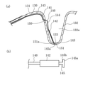
- the extended body has a second through hole at the bottom thereof, and the plurality of electrode engaging portions have a first engaging portion formed from an edge portion of the second through hole, and the plurality of electrodes have the first engaging portion.
- the at least one of the assemblies has a first hook portion that functions as the engaged portion and extends radially inward from the bottom portion through the second through hole from the extending end of the outer arrangement portion.
- the first hook portion may be wider than the portion of the first hook portion that passes through the second through hole, and may have a wide portion that engages with the first engaging portion.
- the plurality of electrode engaging portions have a second engaging portion formed from the edge portion of the third through hole, and the first hook portion passes through the third through hole of the first hook portion. It may have a wide portion that is wider than the portion to be engaged and engages with the second engaging portion. As a result, the electrode assembly is engaged with the second engaging portion by the wide portion while being engaged with the first engaging portion, so that the electrode assembly can be more reliably fixed to the expansion body.
- the expansion body has a second through hole in the base end side curved portion and a fourth through hole in the tip end side upright portion, and the plurality of electrode engaging portions are edges of the second through hole. It has a first engaging portion formed from the portions and a second engaging portion formed from the edge portion of the fourth through hole, and at least one of the plurality of electrode assemblies is arranged outside.
- the first It has a first hook portion that engages with one engaging portion and functions as the engaged portion, and the first hook portion has a width wider than a portion of the first hook portion that passes through the fourth through hole.
- the electrode assembly can be fixed to the expansion body at a portion extending further from the electrode portion to the tip end side, so that the displacement of the electrode portion can be prevented more effectively.
- the extended body has a second through hole in the distal end side curved portion and a third through hole in the proximal end side curved portion, and the plurality of electrode engaging portions are the second through hole and the said. It has a first engaging portion formed between the third through hole and a fourth engaging portion formed from the edge portion of the first through hole, and at least one of the plurality of electrode assemblies.
- the first hook portion that engages with the first engaging portion and functions as the engaged portion, and extends from the extending end of the first hook portion, and extends from the outer arrangement portion and the base end side.
- a first extension portion extending from the upright portion toward the first through hole, and extending from the extending end of the first extension portion to pass through the first through hole and engaging with the fourth engaging portion. It may have a fourth hook portion that functions as the engaged portion.
- At least one of the plurality of electrode assemblies may be adhesively fixed to the extended body at the proximal end side upright portion or the distal end side upright portion.
- the electrode portion can be fixed to the expansion body while the portion on the bottom side of the electrode portion is in a floating state with respect to the expansion body.
- the extended body has a first through hole in the tip-side upright portion, and at least one of the plurality of electrode assemblies extends from the tip end portion of the shaft portion to the proximal end-side upright portion and extends to the tip end-side upright portion.
- An inner arrangement portion extending along the inside of the expansion body to the first through hole of the portion, and a portion from the first through hole to the bottom portion so as to be folded back with respect to the inner arrangement portion and face the receiving space. It may have an outer arrangement portion extending along the extension.
- the electrode portion can be arranged on the side of the upright portion on the tip side with a simple structure.
- the shaft portion has a shaft extension portion extending from the base end fixing portion to the inside of the expansion body along the central axis of the expansion body, and a tip fixing portion to which the tip of the expansion body is fixed.
- the expansion body has a tip side expansion portion extending radially outward from the tip fixing portion of the shaft portion toward the proximal end direction, and the distal end side expansion portion has a proximal end at the outer end of the distal end side standing portion. It has an outwardly curved portion that is connected and curved outward in the radial direction, the tip-side upright portion has a first through hole, and at least one of the plurality of electrode assemblies is said to have the same.
- the shaft arrangement portion extending from the base end fixing portion of the shaft portion to the tip fixing portion along the shaft extension portion, and the extending end of the shaft arrangement portion via the vicinity of the outward curved portion of the tip end side expansion portion.
- An inner arrangement portion extending along the inside of the expansion body to the first through hole, and an outer arrangement portion extending from the first through hole to at least the bottom portion along the expansion body so as to face the receiving space.
- the outward curved portion of the tip-side expansion portion is deformed according to the expansion and contraction of the expansion body, and the inner arrangement portion is at least the outward-facing portion of the tip-side expansion portion when the expansion body is expanded.
- the outer arrangement portion may be in a floating state with respect to the distal end side curved portion and the proximal end side curved portion.
- the extended body has a second through hole in the base end side curved portion, a third through hole in the tip end side curved portion, and a fourth through hole in the tip end side upright portion, and the plurality of electrodes are provided.
- the engaging portion is a first engaging portion formed between the second through hole and the third through hole at the bottom, and a second engaging portion formed at the edge of the fourth through hole.
- at least one of the plurality of electrode assemblies passes through the second through hole from the extending end of the outer arrangement portion, and passes through the radial inner side of the first engagement portion.
- a first hook portion that functions as the engaged portion and engages with the first engaging portion by passing through the third through hole and extending to the outside of the expansion body, and the first hook portion.
- a second hook portion that extends from the extending end and passes through the fourth through hole from the outside to the inside of the expansion body to engage with the second engaging portion and functions as the engaged portion.
- the electrode portion may be arranged between the first hook portion and the second hook portion.
- the expansion body may be formed of a mesh in which a large number of wires are knitted, and at least one of the plurality of electrode assemblies may be inserted between the wires so as to be engaged and fixed.
- the electrode assembly can be fixed to the expansion body formed of the mesh, and the electrode portion can be arranged near the bottom of the recess.
- FIG. 4 (a) a front view
- FIG. 4 (b) a sectional view
- FIG. 4 (b) a front view of an electrode assembly.
- FIG. 4 (a) a front view of the state which combined the electrode assembly with the wire rod part.
- FIG. 4 (b) sectional view of an electrode assembly.
- FIG. 4 (a) a front view of the state which combined the electrode assembly with the wire rod part.
- FIG. 4 (b) sectional drawing of the part near the concave part of the expansion body.
- the medical device is a front view and the living tissue is a cross-sectional view, respectively, schematically showing the state in which the dilated body is arranged in the interatrial septum.
- FIG. 7 is an enlarged view of the vicinity of the extended body in FIG. 7. It is explanatory drawing which shows the state which expanded the diameter of the dilated body in the interatrial septum from the state of FIG. It is sectional drawing of the part near the recess of the expansion body which concerns on 1st modification. It is the sectional view (FIG. 12 (a)) of the part near the recess of the expansion body which concerns on the 2nd modification, and the enlarged front view (FIG. 12 (b)) near the tip of the electrode assembly. It is sectional drawing near the concave part of the expansion body which changed the fixing structure of the 1st hook part from the form of FIG.
- the medical device in the following embodiments is capable of performing maintenance procedures to dilate the puncture hole Hh formed in the atrial septal HA of the patient's heart H and maintain the further dilated puncture hole Hh to its size. It is configured in.
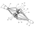
- the medical device 10 of the present embodiment has a long shaft portion 20, an expansion body 21 provided at the tip portion of the shaft portion 20, and an operation unit provided at the base end portion of the shaft portion 20. It has 23 and.
- the extension body 21 is provided with an electrode portion 61 which is an energy transfer element for performing the above-mentioned maintenance measures.
- the shaft portion 20 has a tip portion 30 including a base end fixing portion 31 to which the base end of the expansion body 21 is fixed and a tip fixing portion 33 to which the tip end of the expansion body 21 is fixed.
- the tip portion 30 of the shaft portion 20 has a shaft extension portion 32 extending in the extension body 21 from the base end fixing portion 31.
- the shaft portion 20 has a storage sheath 25 provided on the outermost peripheral portion.
- the expansion body 21 can move forward and backward in the axial direction with respect to the storage sheath 25.
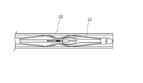
- the storage sheath 25 can store the expansion body 21 inside the storage sheath 25 in a state of being moved to the tip end side of the shaft portion 20. By moving the storage sheath 25 from the state in which the expansion body 21 is stored to the base end side, the expansion body 21 can be exposed.
- the shaft portion 20 has a tow shaft 26.
- the tow shaft 26 is provided from the base end of the shaft portion 20 to the shaft extension portion 32, and the tip portion thereof is fixed to the tip member 35.
- the tip member 35 to which the tip of the tow shaft 26 is fixed does not have to be fixed to the expansion body 21. As a result, the tip member 35 can pull the expansion body 21 in the compression direction. Further, when the expansion body 21 is stored in the storage sheath 25, the tip member 35 is separated from the expansion body 21 toward the tip side, so that the expansion body 21 can be easily moved in the extending direction and the storage property can be improved. can.
- the operation unit 23 has a housing 40 gripped by the operator, an operation dial 41 that can be rotated by the operator, and a conversion mechanism 42 that operates in conjunction with the rotation of the operation dial 41.
- the traction shaft 26 is held by the conversion mechanism 42 inside the operation unit 23.
- the conversion mechanism 42 can move the tow shaft 26 to be held forward and backward along the axial direction as the operation dial 41 rotates.
- a rack and pinion mechanism can be used as the conversion mechanism 42.
- the shaft portion 20 is preferably formed of a material having a certain degree of flexibility.
- a material having a certain degree of flexibility examples include polyolefins such as polyethylene, polypropylene, polybutene, ethylene-propylene copolymer, ethylene-vinyl acetate copolymer, ionomer, or a mixture of two or more thereof, and a soft polyvinyl chloride resin.
- fluororesins such as polyamide, polyamide elastomer, polyester, polyester elastomer, polyurethane and polytetrafluoroethylene, polyimide, PEEK, silicone rubber and latex rubber.
- the traction shaft 26 includes, for example, a superelastic alloy such as a nickel-titanium alloy or a copper-zinc alloy, a metal material such as stainless steel, a long wire such as a relatively rigid resin material, and a polyvinyl chloride or polyethylene. , Polyethylene, or a resin material such as an ethylene-propylene copolymer.
- a superelastic alloy such as a nickel-titanium alloy or a copper-zinc alloy
- a metal material such as stainless steel
- a long wire such as a relatively rigid resin material
- polyvinyl chloride or polyethylene polyethylene
- Polyethylene or a resin material such as an ethylene-propylene copolymer.
- the tip member 35 is, for example, a polymer material such as polyolefin, polyvinyl chloride, polyamide, polyamide elastomer, polyurethane, polyurethane elastomer, polyimide, fluororesin, or a mixture thereof, or a multilayer tube of two or more kinds of polymer materials. Can be formed.
- a polymer material such as polyolefin, polyvinyl chloride, polyamide, polyamide elastomer, polyurethane, polyurethane elastomer, polyimide, fluororesin, or a mixture thereof, or a multilayer tube of two or more kinds of polymer materials. Can be formed.
- the expansion body 21 has a plurality of wire rod portions 50 in the circumferential direction.
- four wire rod portions 50 are provided in the circumferential direction.
- Each of the wire rod portions 50 can be expanded and contracted in the radial direction.
- the base end of the wire rod portion 50 is fixed to the base end fixing portion 31, and extends from the base end fixing portion 31 toward the tip end side.
- the tip of the wire rod portion 50 is fixed to the tip fixing portion 33, and extends from the tip fixing portion 33 toward the base end side.
- the wire rod portion 50 is inclined so as to increase in the radial direction from both end portions in the axial direction toward the center portion.
- the wire rod portion 50 has a recess 51 recessed inward in the radial direction of the expansion body 21 in the central portion in the axial direction.
- the innermost portion in the radial direction of the recess 51 is the bottom portion 52.
- the wire rod portion 50 has a second through hole 81 and a third through hole 82 in a portion serving as a bottom portion 52, and a first engaging portion 83 serving as an electrode engaging portion between them. have.
- a first through hole 80 is formed on the proximal end side of the second through hole 81, and a fourth through hole 84 is formed on the distal end side of the third through hole 82.
- the tip side of the wire rod portion 50 from the bottom portion 52 has a slit-shaped central portion in the width direction, and has outer edge portions 58 on both sides and a back support portion 59 at the central portion.
- the wire rod portion 50 forming the expansion body 21 has, for example, a flat plate shape cut out from a cylinder.
- the wire rod forming the expansion body 21 can have a thickness of 50 to 500 ⁇ m and a width of 0.3 to 2.0 mm. However, it may have dimensions outside this range.
- the wire rod portion 50 may have a circular cross-sectional shape or a cross-sectional shape other than that.
- An electrode assembly 22 separate from the expansion body 21 is attached to the expansion body 21.
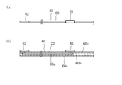
- the electrode assembly 22 is provided at the long wiring portion 60, the electrode portion 61 provided at the intermediate portion in the length direction of the wiring portion 60, and the base end portion of the wiring portion 60. It has a connection portion 62.
- the wiring portion 60 has a conductive wire portion 60a.
- the electric wire portion 60a, the electrode portion 61, and the connecting portion 62 can be formed of a metal material.
- the electric wire portion 60a is embedded in the adhesive layer 60b sandwiched between the insulating layers 60c provided on the surfaces of both sides of the wiring portion 60 in the thickness direction.
- the electrode portion 61 is provided so as to be exposed on the surface of the insulating layer 60c, and is electrically connected to the electric wire portion 60a.
- the connection portion 62 is a portion that electrically connects the electrode assembly 22 to a connection line (not shown) provided on the proximal end side of the medical device 1, and is connected to the surface of the insulating layer 60c like the electrode portion 61. It is exposed and is conducting with the electric wire portion 60a.
- the electrode unit 61 is composed of, for example, a bipolar electrode that receives electrical energy from an energy supply device (not shown) which is an external device. In this case, energization is performed between the electrode portions 61 arranged in each wire rod portion 50.
- the electrode portion 61 and the energy supply device are connected by a conducting wire (not shown) coated with an insulating coating material. The conducting wire is led out to the outside via the shaft portion 20 and the operating portion 23, and is connected to the energy supply device.
- the electrode portion 61 may also be configured as a monopolar electrode. In this case, electricity is supplied to the counter electrode plate prepared outside the body. Further, instead of the electrode portion 61, a heat generating element (electrode chip) that receives high frequency electric energy from the energy supply device and generates heat may be used. In this case, energization is performed between the heat generating elements arranged in each wire rod portion 50. Further, the electrode portion 61 includes microwave energy, ultrasonic energy, coherent light such as a laser, a heated fluid, a cooled fluid, a material that exerts heating and cooling actions by a chemical medium, and a material that generates frictional heat. It can be configured by an energy transfer element capable of applying energy to the puncture hole Hh, such as a heater provided with an electric wire or the like, and the specific form is not particularly limited.
- an energy transfer element capable of applying energy to the puncture hole Hh, such as a heater provided with an electric wire or the like, and the specific form is not particularly limited.
- the wire rod portion 50 can be formed of a metal material.
- the metal material for example, titanium-based (Ti—Ni, Ti—Pd, Ti—Nb—Sn, etc.) alloys, copper-based alloys, stainless steels, ⁇ -titanium steels, and Co—Cr alloys can be used. .. It is better to use an alloy having a spring property such as a nickel-titanium alloy.
- the material of the wire rod portion 50 is not limited to these, and may be formed of other materials.
- the electrode assembly 22 is fixed by being engaged with the wiring portion 60 along the surface of the wire rod portion 50 so as to be hooked on a plurality of electrode engaging portions of the expansion body 21.
- the wire rod portion 50 is recessed inward in the radial direction, and has a recess 51 that defines a receiving space 51a that can receive a living tissue when the expanded body 21 is expanded.
- the wire rod portion 50 has a proximal end side curved portion 52a which is a portion on the proximal end side of the bottom portion 52 which is the innermost portion in the radial direction of the recess 51, and a distal end side curved portion 52b which is a portion on the distal end side of the bottom portion 52. ing.
- the wire rod portion 50 has a proximal end side upright portion 53 extending radially outward from the proximal end side curved portion 52a and a distal end side erecting portion extending radially outward from the distal end side curved portion 52b toward the distal end side. It has a portion 54 and. Further, the wire rod portion 50 has a proximal end side expansion portion 55 extending radially outward from the proximal end fixing portion 31 of the shaft portion 20 and the distal end fixing portion 33 of the shaft portion 20 toward the proximal end side. It has a tip-side expansion portion 56 extending radially outward.
- the base end side expansion portion 55 has an outward bending portion whose tip is connected to the outer end of the base end side upright portion 53 and which is curved outward in a radial direction and deforms according to the expansion and contraction of the expansion body 21.
- the distal end side expansion portion 56 has a base end connected to the outer end of the distal end side upright portion 54 and is curved outward in a radial direction, and is deformed outward according to the expansion and contraction of the expansion body 21. It has a portion 57.
- the base end side upright portion 53 has a first through hole 80, and a third engaging portion 80a as an electrode engaging portion for engaging the electrode assembly 22 is formed by the edge portion thereof.
- the base end side curved portion 52a has a second through hole 81
- the tip end side curved portion 52b has a third through hole 82
- an electrode engagement is provided between the second through hole 81 and the third through hole 82.
- the first engaging portion 83 as a joint is formed.
- the first engaging portion 83 has a form in which both ends in the width direction are crosslinked at the bottom portion 52 of the wire rod portion 50.
- the tip-side upright portion 54 has a fourth through hole 84, and a second engaging portion 84a as an electrode engaging portion is formed by the edge portion thereof.
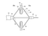
- the electrode assembly 22 runs from the tip portion 30 of the shaft portion 20 toward the tip end along the inside of the expansion body 21 to the first through hole 80 via the vicinity of the outward curved portion 57 of the proximal end side expansion portion 55. It has an inner arrangement portion 70 extending from the inside. The inner arrangement portion 70 is separated from the outward curved portion 57 of the wire rod portion 50 when the expansion body 21 is expanded. Therefore, even if the outward curved portion 57 is deformed when the expansion body 21 is expanded or contracted, it is possible to prevent the electrode assembly 22 from being damaged.
- the electrode assembly 22 has an outer arrangement portion 71 extending from the first through hole 80 to the bottom portion 52 of the recess 51 along the expansion body 21 so as to face the receiving space 51a.
- the electrode portion 61 is arranged in the outer arrangement portion 71 and faces the receiving space 51a.
- the electrode assembly 22 passes through the second through hole 81 from the extending end of the outer arrangement portion 71, passes through the third through hole 82 via the radial inside from the first engaging portion 83, and passes through the third through hole 82 of the expansion body 21. It has a first hook portion 72 that engages with the first engaging portion 83 so as to be hooked by extending outward.
- the first hook portion 72 functions as an engaged portion that engages with the first engaging portion 83, which is an electrode engaging portion.
- extended end refers to the "extended end” in the extending direction when the plurality of electrode assemblies 22 extend from the tip of the shaft portion 20 or the tip of the extended body 21 along the extended body 21, respectively. It shows the end. It should be noted that one of the plurality of electrode assemblies 22 may extend from the tip end portion of the expansion body 21, and the other electrode assembly 22 may extend from the tip end portion of the shaft portion 20.
- the electrode portion 61 is provided in the electrode assembly 22 which is separate from the wire rod portion 50 forming the expansion body 21, the electrode portion 61 is arranged at a position close to the bottom portion 52 which is the innermost radial direction of the recess 51. Can be done. Further, since the electrode portion 61 is not fixed to the proximal end side curved portion 52a and the distal end side curved portion 52b that are deformed by the expansion and contraction of the expansion body 21 and is in an idle state, the electrode portion 61 is the expansion body 21. It can be prevented from being damaged by the deformation of.
- the electrode assembly 22 extends from the extending end of the first hook portion 72 and passes through the fourth through hole 84 from the outside to the inside of the expansion body 21 to engage with the second engaging portion 84a. It has a hook portion 73.
- the second hook portion 73 functions as an engaged portion that engages with the second engaging portion 84a, which is an electrode engaging portion.
- the second hook portion 73 has a folded portion 73a that passes through the fourth through hole 84 and extends inside the expansion body 21 toward the bottom portion 52. The second hook portion 73 securely fixes the electrode assembly 22 to the wire rod portion 50, and can prevent the electrode portion 61 from being displaced.
- the electrode assembly 22 engages with the first engaging portion 83 by extending from the extending end of the second hook portion 73, passing through the inside of the expansion body 21, passing through the second through hole 81, and extending to the outside of the expansion body 21. It has a matching third hook portion 74.
- the third hook portion 74 functions as an engaged portion that engages with the first engaging portion 83, which is an electrode engaging portion.
- the electrode assembly 22 has a first extension portion 84 extending from the extending end of the third hook portion 74 and extending between the outer arrangement portion 71 and the proximal end side upright portion 53 toward the first through hole 80. is doing.
- the base end side upright portion 53 and the first extension portion 84 are covered with the first cover 65.
- a heat-shrinkable tube or the like can be used for the first cover 65.
- the first cover 65 allows the electrode assembly 22 to reliably follow the movement of the base end side upright portion 53 when the expansion body 21 is expanded or contracted. As a result, it is possible to prevent the electrode assembly 22 from coming into contact with an unintended portion and being damaged. Further, since the portion of the electrode assembly 22 covered by the first cover 65 can be slidably moved in the length direction, an excessive deformation force is locally applied to the electrode assembly 22 when the expansion body 21 is expanded or contracted. This can be prevented.
- the electrode assembly 22 has a fourth hook portion 76 that extends from the extending end of the first extension portion 84, passes through the first through hole 80, and engages with the third engaging portion 80a.
- the fourth hook portion 76 functions as an engaged portion that engages with the third engaging portion 80a, which is an electrode engaging portion.
- the fourth hook portion 76 has a crank portion 76a extending from the extending end of the first extension portion 84 through the first through hole 80 and along the inside of the expansion body 21.
- the electrode assembly 22 has a second extension portion 77 that extends from the extending end of the crank portion 76a and extends radially inside from the inner arrangement portion 70 along the inner arrangement portion 70.
- the second extension portion 77, the inner arrangement portion 70, and the proximal end side expansion portion 55 are covered with the second cover 66.
- a heat-shrinkable tube or the like can be used for the second cover 66.
- the second cover 66 also prevents the electrode assembly 22 from coming into contact with an unintended portion, and when the expansion body 21 is expanded or contracted, an excessive deformation force is locally applied to the electrode assembly 22. This can be prevented.
- the expansion body 21 housed in the storage sheath 25 is in a state of being contracted in the radial direction.
- the expansion body 21 and the storage sheath 25 move in the axial direction with each other, the expansion body 21 is exposed to the outside of the storage sheath 25 and expands in the radial direction.
- the treatment method using the medical device 10 will be described.
- the treatment method of this embodiment is performed on a patient suffering from heart failure (left heart failure). More specifically, as shown in FIG. 8, for patients suffering from chronic heart failure in which the blood pressure of the left atrium HLa increases due to the enlargement of the myocardium of the left ventricle of the heart H and the increase in stiffness (hardness). This is the method of treatment performed.
- the treatment method of the present embodiment includes a step (S1) of forming a puncture hole Hh in the atrial septal HA, a step (S2) of arranging the dilator 21 in the puncture hole Hh, and a diameter of the puncture hole Hh by the dilator 21.
- Step (S3) step to confirm hemodynamics in the vicinity of the puncture hole Hh (S4), step to perform maintenance measures to maintain the size of the puncture hole Hh (S5), and maintenance measures are performed. It has a step (S6) for confirming hemodynamics in the vicinity of the puncture hole Hh after the puncture hole has been performed.
- the surgeon delivers the introducer 310, which is a combination of a guiding sheath and a dilator, to the vicinity of the atrial septal HA when forming the puncture hole Hh.
- the introducer 310 can be delivered to the right atrium HRa, for example, via the inferior vena cava Iv. Further, the delivery of the introducer can be performed by using the guide wire 11.
- the surgeon can insert the guide wire 11 through the dilator and deliver the introducer along the guide wire 11. It should be noted that the insertion of the introducer into the living body, the insertion of the guide wire 11 and the like can be performed by a known method such as using an introducer for introducing a blood vessel.
- the operator penetrates the puncture device (not shown) from the right atrium HRa side toward the left atrium HLa side to form a puncture hole Hh.
- the puncture device for example, a device such as a wire having a sharp tip can be used.
- the puncture device is inserted through a dilator and delivered to the atrial septal HA.
- the puncture device can be delivered to the atrial septal HA in place of the guide wire 11 after removing the guide wire 11 from the dilator.
- the medical device 10 is delivered to the vicinity of the atrial septal HA along the guide wire 11 inserted in advance. At this time, the tip of the medical device 10 penetrates the atrial septum HA and reaches the left atrium HLa. Further, when the medical device 10 is inserted, the expansion body 21 is in a state of being housed in the storage sheath 25.
- the expansion body 21 is exposed by moving the storage sheath 25 toward the base end side.
- the dilated body 21 is expanded in diameter, and the recess 51 is arranged in the puncture hole Hh of the atrial septum HA to receive the biological tissue surrounding the puncture hole Hh in the receiving space 51a.
- the biological tissue is sandwiched between the proximal end side upright portion 53 having the electrode portion 61 and the distal end side upright portion 54.
- the operator operates the operation unit 23 in a state where the receiving space 51a receives the living tissue, and moves the traction shaft 26 to the proximal end side.
- the expansion body 21 is further expanded in the radial direction, and the puncture hole Hh is expanded in the radial direction.
- the operator After expanding the puncture hole Hh, check the hemodynamics in the step of S4. As shown in FIG. 8, the operator delivers the hemodynamic confirmation device 320 to the right atrium HRa via the inferior vena cava Iv.
- the hemodynamic confirmation device 320 for example, a known echo catheter can be used. The surgeon can display the echo image acquired by the hemodynamic confirmation device 320 on a display device such as a display, and confirm the blood volume passing through the puncture hole Hh based on the display result.
- the operator performs a maintenance procedure to maintain the size of the puncture hole Hh.
- the maintenance procedure high-frequency energy is applied to the edge of the puncture hole Hh through the electrode portion 61, so that the edge of the puncture hole Hh is cauterized (heated and cauterized) by the high-frequency energy.
- the puncture hole Hh When the biological tissue near the edge of the puncture hole Hh is cauterized through the electrode portion 61, a degenerated portion in which the biological tissue is denatured is formed near the edge. Since the biological tissue in the degenerated portion loses its elasticity, the puncture hole Hh can maintain its shape when expanded by the dilator 21.
- the hemodynamics are confirmed again in the step of S6, and when the amount of blood passing through the puncture hole Hh is a desired amount, the operator reduces the diameter of the dilator 21 and stores it in the storage sheath 25. Then, it is removed from the puncture hole Hh. Further, the entire medical device 10 is removed from the living body, and the treatment is completed.
- the wire rod portion 101 of the expansion body 100 has a proximal end side curved portion 103a and a distal end side curved portion 103b at the bottom portion 103 of the recess 102.
- a second through hole 121 is formed in the distal end side curved portion 103b, and a third through hole 122 is formed in the proximal end side curved portion 103a.
- 1 Engagement portion 123 is formed. The first engaging portion 123 is arranged slightly closer to the base end side in the bottom portion 103 of the recess 102.
- a first through hole 120 is formed in the base end side upright portion 104 of the wire rod portion 101.
- the electrode assembly 110 has an inner arrangement portion 113 on the proximal end side of the first through hole 120 and an outer arrangement portion 114 on the distal end side of the first through hole 120, respectively.
- An electrode portion 112 is arranged in the outer arrangement portion 114 so as to face the receiving space 102b.
- the electrode assembly 110 passes through the second through hole 121 of the distal end side curved portion 103b from the extending end of the outer arrangement portion 114, passes through the radial inside from the first engaging portion 123, and is the proximal end side curved portion 103a. It has a first hook portion 115 that engages with the first engaging portion 123 by passing through the third through hole 122 and extending to the outside of the expansion body 100. Since the first engaging portion 123 is arranged closer to the proximal end side than the bottom portion 102a, the electrode portion 112 can be arranged along the proximal end side standing portion 104.
- the wiring portion 111 has a first extension portion 116 extending from the extending end of the first hook portion 115 and extending from the outer arrangement portion 114 and the base end side upright portion 104 toward the first through hole 120. There is. Further, the wiring portion 111 extends from the extending end of the first extension portion 116, passes through the first through hole 120, and engages with the fourth engagement portion 120a formed at the edge portion of the first through hole 120. It has a fourth hook portion 117. In this way, the electrode assembly 110 may be folded back at the first engaging portion 123 formed in the bottom portion 102a of the recess 102.
- the wire rod portion 131 of the expansion body 130 has a recess 132.
- a second through hole 151 is formed in the bottom 133 of the recess 132.
- a first engaging portion 152 is formed at the edge of the second through hole 151.
- the electrode assembly 140 has an inner arrangement portion 143 on the proximal end side of the first through hole 150 and an outer arrangement portion 144 on the distal end side of the first through hole 150, respectively.
- An electrode portion 142 is arranged in the outer arrangement portion 114 so as to face the receiving space 132a.
- the wiring portion 141 has a first hook portion 145 extending radially inward from the bottom portion 133 through the second through hole 151 from the extending end of the outer arrangement portion 114.
- the first hook portion 145 is wider than the passing portion 145b passing through the second through hole 151 of the first hook portion 145, and is wider to engage with the first engaging portion 152.
- It has a portion 145a.
- the first hook portion 145 is fixed to the wire rod portion 131 by engaging the wide portion 145a so as to be hooked on the first engaging portion 152.
- the electrode assembly 140 may use the wide portion 145a provided at the tip end portion as the engaged portion.
- the fixed structure of the first hook portion 145 having the wide portion 145a may be another form.
- the expansion body 130 has a second through hole 155 in the proximal end side curved portion 133a and a third through hole 156 in the distal end side curved portion 133b, respectively, and has a second through hole 155 and a second through hole 156.
- a first engaging portion 157 is formed between the three through holes 156.
- the first hook portion 145 passes through the second through hole 155 from the extending end of the outer arrangement portion 144, passes through the third through hole 156 via the radial inside from the first engaging portion 157, and passes through the expansion body. By extending to the outside of 130, it engages with the first engaging portion 157. Further, the wide portion 145a of the first hook portion 145 is caught and engaged with the second engaging portion 156a formed by the edge portion of the third through hole 156.
- the expansion body 130 may have a fourth through hole 158 in the tip-side upright portion 135, and a second engagement portion 158a may be formed at the edge portion of the fourth through hole 158.
- the first hook portion 145 that has passed through the second through hole 155 may be extended to the fourth through hole 158 so that the wide portion 145a engages with the second engaging portion 158a.
- the expansion body 170 and the electrode assembly 180 according to the third modification will be described.
- the configuration of the expansion body 170 is the same as that in FIG. 6, the first through hole 190 is provided in the proximal end side upright portion 174, the second through hole 191 is provided in the proximal end side curved portion 173a, and the distal end side is provided.
- the curved portion 173b has a third through hole 192, and the tip-side upright portion 175 has a fourth through hole 194.
- the expansion body 170 is formed as an electrode engaging portion by a first engaging portion 193 formed between the second through hole 191 and the third through hole 192 of the bottom portion 173 and an edge portion of the fourth through hole 194. It has a second engaging portion 194a and the like.
- the electrode assembly 180 passes through the second through hole 191 from the extending end of the outer arrangement portion 184, passes through the third through hole 192 via the radial inside from the first engaging portion 193, and passes through the third through hole 192 of the expansion body 170. It has a first hook portion 185 that engages with the first engaging portion 193 by extending outward. Further, the electrode assembly 180 extends from the extending end of the first hook portion 185 and passes through the fourth through hole 194 from the outside to the inside of the expansion body 170 to engage with the second engaging portion 194a. It has a second hook portion 187. The electrode portion 182 is arranged between the first hook portion 185 and the second hook portion 187. Therefore, the electrode portion 182 is arranged along the tip-side upright portion 175 of the recess 172. In this way, the electrode portion 182 may be arranged on the tip end side of the recess 172.
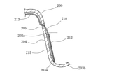
- the expansion body 200 has a first through hole 205 in the base end side upright portion 204.
- the electrode assembly 210 has an inner arrangement portion 213 and an outer arrangement portion 214 with the first through hole 205 interposed therebetween, and the outer arrangement portion 214 is arranged along the proximal end side upright portion 204.
- An electrode portion 212 is arranged on the outer arrangement portion 214. The electrode portion 212 faces the receiving space 202a, and the back side thereof is adhesively fixed to the expansion body 200 by the adhesive portion 215.
- the adhesive portion 215 is provided in the radial outer region of the electrode portion 212, and is arranged so as not to reach the proximal end side curved portion 203a and the distal end side curved portion 203b of the expansion body 200. Therefore, the outer arrangement portion 214 in which the electrode portion 212 is arranged is in an idle state with respect to the proximal end side bending portion 203a and the distal end side bending portion 203b. In this way, the electrode assembly 200 may be fixed by adhesive, and in this case as well, the adhesive portion 215 is formed so that the electrode portion 212 is in a floating state with respect to the proximal end side curved portion 203a and the distal end side curved portion 203b. By doing so, the electrode portion 212 can be arranged so as to extend to the vicinity of the bottom portion 203.
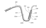
- the expansion body 220 and the electrode assembly 230 according to the fifth modification will be described.
- the expansion body 220 has a first through hole 226 in the tip-side upright portion 225.
- the electrode assembly 230 has an inner arrangement portion 233 extending along the inside of the expansion body 220 from the tip portion 30 of the shaft portion 20 to the first through hole 226 of the distal end side upright portion 230 beyond the proximal end side upright portion 224. is doing.
- the expansion body 220 has an outer arrangement portion 234 extending along the expansion body 220 from the first through hole 226 to the bottom portion 223 so as to be folded back with respect to the inner arrangement portion 233 and face the receiving space 222a. There is.
- the electrode portion 232 is arranged along the outer arrangement portion 234, and is fixed to the outer arrangement portion 234 by the adhesive portion 235.
- the adhesive portion 235 is arranged so as not to reach the proximal end side curved portion 223a and the distal end side curved portion 223b, and the region on the bottom portion 223 side of the outer arrangement portion 234 in which the electrode portion 232 is arranged is curved toward the proximal end side. It is in an idle state with respect to the portion 223a and the distal end side curved portion 223b.
- the inner arrangement portion 233 may be long and the electrode portion 232 may be arranged along the tip side upright portion 225.
- the fixing of the electrode assembly 230 is not limited to adhesion, and may be fixed by a plurality of electrode engaging portions described above.
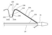
- the tip-side upright portion 245 of the expansion body 240 has a first through hole 246.
- the electrode assembly 250 has a shaft arranging portion 253 extending along the shaft extension portion 32 from the base end fixing portion 31 of the shaft portion 20 to the tip fixing portion 33.
- the electrode assembly 250 extends from the extending end of the shaft arrangement portion 253 to the first through hole 246 via the vicinity of the outward curved portion 248 of the distal end side expansion portion 247 along the inner arrangement portion 254 of the extension body 240.
- an outer arrangement portion 255 extending from the first through hole 246 to the vicinity of the bottom portion 243 along the expansion body 240 so as to face the receiving space 242a.
- the inner arrangement portion 254 is separated from the outward curved portion 248 of the distal end side expansion portion 247 when the expansion body 240 is expanded.
- the outer arrangement portion 255 having the electrode portion 252 is adhesively fixed to the expansion body 240 by the adhesive portion 256.
- the adhesive portion 256 is arranged so as not to reach the proximal end side curved portion 243a and the distal end side curved portion 243b, and the region on the bottom portion 243 side of the outer arrangement portion 255 is the proximal end side curved portion 243a and the distal end side curved portion.
- the electrode assembly 250 may have a portion along the shaft portion 20.
- the fixing of the electrode assembly 250 is not limited to adhesion, and may be fixed by a plurality of electrode engaging portions described above.
- the expansion body 260 and the electrode assembly 270 according to the seventh modification will be described.
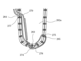
- the expansion body 260 is formed of a mesh in which a large number of wire rods 261 are knitted.
- the expansion body 260 has a recess 262, and an electrode portion 272 is arranged in the base end side upright portion 264 thereof.
- the electrode assembly 270 is engaged with the expansion body 260 by being inserted into the space between the wire rods 261.
- the electrode assembly 270 has a first hook portion 274 that engages with the bottom portion 263, a second hook portion 275 that engages with the tip side upright portion 265, and a first hook portion 274. It has a third hook portion 276 that passes through the inside in the radial direction and engages with the bottom portion 263, and a fourth hook portion 277 that engages with the base end side upright portion 264. Further, the outer arrangement portion 273 having the electrode portion 272 is arranged so as to face the receiving space 262a, and is in a floating state with respect to the bottom portion 263.
- the electrode assembly 270 can be fixed so as to follow the outer shape of the expansion body 260 formed of the mesh.
- the fixing of the electrode assembly 270 is not limited to this example, and any of the fixing by the plurality of electrode engaging portions described above may be applied.
- the expansion body includes an expansion body 21 in which a plurality of wire rod portions 50 are fixed to the base end fixing portion 31 and the tip fixing portion 33 of the shaft portion 20, respectively, and an expansion formed of a mesh. It may be different from the body 260.
- an expansion body having a plurality of wire rod portions has a proximal end side expansion portion and a distal end side expansion portion, the proximal end side expansion portion is fixed to the proximal end fixing portion of the shaft portion, and the distal end side expansion portion is bundled. It may not be fixed.
- the expansion body having a plurality of wire rod portions may have a proximal end side expansion portion fixed to the proximal end fixing portion and may not have the distal end side expansion portion.
- the electrode assembly may have a wide portion having a width larger than the electrode engaging portion of the extended body at the end or the intermediate position in the extending direction to be the engaged portion.
- a wide portion may be provided in the fourth hook portion 76 to serve as the end of the electrode assembly 22.
- wide portions may be provided in the front and rear portions of the second hook portion 73 before and after passing through the fourth through hole 84 so as to engage with the second engaging portion 84a.
- the plurality of electrode assemblies 22 may have different fixing structures.
- the structure of the electrode assembly 22 shown in FIG. 6 may be adopted for two of the four wire rod portions 50, and the structure of the electrode assembly 180 shown in FIG. 15 may be adopted for the remaining two wire rod portions 50. can.
- the electrode assembly 22 may adopt a combination other than this.
- the medical device 10 is a long length having an expansion body 21 that can be expanded and contracted in the radial direction and a tip portion 30 including a proximal end fixing portion 31 to which the proximal end of the expansion body 21 is fixed.
- a shaft portion 20 and a plurality of electrode assemblies 22 extending from a base end fixing portion 31 of the shaft portion 20 along at least a part of the expansion body 21.
- the expansion body 21 is recessed inward in the radial direction and is an expansion body.
- the recess 51 has a recess 51 that defines a receiving space 51a that can receive the biological tissue when the 21 is expanded, and the recess 51 is a bottom portion located on the innermost side in the radial direction including the proximal end side curved portion 52a and the distal end side curved portion 52b.
- a plurality of electrode assemblies 22 having a base end side upright portion 53 extending radially outward from the proximal end side curved portion 52a, and a distal end side upright portion 54 extending radially outward from the distal end side curved portion 52b.
- Each has an electrode portion 61 arranged along the extension body 21 from the proximal end side upright portion 53 or the distal end side upright portion 54 to the bottom portion 52 so as to face the receiving space 51a, and has a proximal end side curved portion 52a.
- the distal end side curved portion 52b is deformed according to the expansion and contraction of the expansion body 21, and the electrode portion 61 is in an idle state with respect to the distal end side curved portion 52b and the proximal end side curved portion 52a.
- the electrode portion 61 is provided in the electrode assembly 22 separate from the expansion body 21, the electrode portion 61 is arranged at a position close to the bottom portion 52 which is the innermost radial direction of the recess 51.
- the electrode portion 61 is not fixed to the proximal end side curved portion 52a and the distal end side curved portion 52b that are deformed by the expansion and contraction of the expansion body 21 and is in an idle state, the electrode portion 61 is arranged at a position close to the bottom portion 52. It is possible to prevent the electrode portion 61 from being damaged due to deformation of the expansion body 21.
- the expansion body 21 has a plurality of electrode engaging portions for engaging each of the plurality of electrode assemblies 22 with the expansion body 21, and the plurality of electrode assemblies 22 are engaged with each other to engage with the electrode engaging portions. It has a joint portion, and the electrode engaging portion may be provided on at least one of the bottom portion 52, the proximal end side upright portion 52a, and the distal end side upright portion 52b. As a result, the electrode assembly is engaged with and fixed to the plurality of electrode engaging portions of the expansion body 21, so that the electrode portion 61 can be fixed so as not to be displaced with respect to the expansion body 21.
- the expansion body 21 has a proximal end side expansion portion 55 extending radially outward from the proximal end fixing portion 31 of the shaft portion 20, and the distal end of the proximal end side expansion portion 55 is on the proximal end side.
- a first through hole 80 that is connected to the outer end of the upright portion 53 and has an outward curved portion 57 that is curved outward in the radial direction, and the base end side upright portion 53 penetrates the expansion body 21.
- At least one of the plurality of electrode assemblies 22 of the expansion body 21 extends from the tip portion 30 of the shaft portion 20 to the first through hole 80 via the vicinity of the outward curved portion 57 of the proximal end side expansion portion 55.
- the outer arrangement portion 71 may be idle with respect to the distal end side curved portion 52b and the proximal end side curved portion 51a. As a result, it is possible to prevent the electrode assembly 22 from interfering with the expansion body 21 and being damaged.
- the expansion body 21 has a second through hole 81 in the base end side curved portion 52a and a third through hole 82 in the tip end side curved portion 52b, and the plurality of electrode engaging portions are the second through portions of the bottom portion 52.
- a first engaging portion 83 is provided between the two through holes 81 and the third through hole 82, and at least one of the plurality of electrode assemblies 22 has a second through hole 81 from the extending end of the outer arrangement portion 71. Passes through the third through hole 82 from the first engaging portion 83 via the inside in the radial direction, and extends to the outside of the expansion body 21 to engage with the first engaging portion 83. It may have a first hook portion 72 that functions as a joint portion.
- the electrode assembly 22 can be made to follow the expansion and contraction of the expansion body 21 while the electrode portion 61 is arranged near the bottom portion 52 of the expansion body 21, and both can be prevented from rubbing against each other and being damaged.
- the expansion body 21 has a fourth through hole 84 in the tip-side upright portion 54, and the plurality of electrode engaging portions have a second engaging portion 84a formed from the edge portion of the fourth through hole 84.
- at least one of the plurality of electrode assemblies 22 extends from the extending end of the first hook portion 72 and passes through the fourth through hole 84 from the outside to the inside of the expansion body 21 to perform the second engagement.
- a second hook portion 73 that functions as an engaged portion that engages with the portion 84a may be provided.
- the electrode assembly 22 can be more strongly fixed to the expansion body 21, and the misalignment of the electrode portion 61 can be prevented.
- the second hook portion 73 may have a folded portion 73a that passes through the fourth through hole 84 and extends inside the expansion body 21 toward the bottom portion 52. As a result, the electrode assembly 22 can be more reliably fixed to the expansion body 21.
- At least one of the plurality of electrode assemblies 22 extends from the extending end of the second hook portion 73 to the outside of the expansion body 21 through the inside of the expansion body 21 and the second through hole 81. It may have a third hook portion 74 that engages with the first engaging portion 83 and functions as an engaged portion.
- the electrode assembly 22 can be fixed to the expansion body 21 at a portion extending further from the electrode portion 61 to the tip end side, so that the misalignment of the electrode portion 61 can be prevented more effectively.
- At least one of the plurality of electrode assemblies 22 extends from the extending end of the third hook portion 74, and extends between the outer arrangement portion 71 and the proximal end side upright portion 53 toward the first through hole 80.
- One extension portion 75 may be provided, and the medical device 10 may further include a first cover 65 that covers the proximal end side upright portion 53 and the first extension portion 75.
- At least one of the plurality of electrode assemblies 22 has an electrode portion 61 in the outer arrangement portion 71, and the first cover 65 is arranged so as to be sandwiched between the outer arrangement portion 71 and the first extension portion 75. You may do so. As a result, the electrode assembly 22 can be made to follow the expansion and contraction of the expansion body 21 while exposing the electrode portion 61 to the outside of the first cover 65.
- the plurality of electrode engaging portions have a third engaging portion 80a formed from the edge portion of the first through hole 80, and at least one of the plurality of electrode assemblies 22 is an extension of the third hook portion 74.
- a first extension portion 75 extending from the existing end and extending between the outer arrangement portion 71 and the base end side upright portion 53 toward the first through hole 80, and a first extending portion extending from the extending end of the first extension portion 75. It may have a fourth hook portion 76 that passes through the through hole 80 and engages with the third engaging portion 80a and functions as an engaged portion.
- the fourth hook portion 76 may have a crank portion 76a extending from the extending end of the first extension portion 75 through the first through hole 80 and along the inside of the expansion body 21. As a result, the electrode assembly 22 can be more reliably engaged with the expansion body 21.
- At least one of the plurality of electrode assemblies 22 has a second extension portion 77 extending from the extending end of the crank portion 76a and extending radially inside from the inner arrangement portion 70 along the inner arrangement portion 70.
- the medical device 10 may further include a second cover 66 that covers the second extension 77, the inner disposition 70, and the proximal extension 55.
- the expansion body 130 has a second through hole 151 in the bottom portion 133, and the plurality of electrode engaging portions have a first engaging portion 152 formed from the edge portion of the second through hole 151, and a plurality of electrode engaging portions.
- At least one of the electrode assemblies 140 of the outer arrangement portion 144 has a first hook portion 145 that functions as an engaged portion and extends radially inward from the bottom portion 133 through the second through hole 155 from the extending end of the outer arrangement portion 144. Even if the first hook portion 145 has a wider portion than the portion of the first hook portion 145 that passes through the second through hole 151 and has a wide portion 145a that engages with the first engaging portion 152. good.
- the electrode portion 142 is arranged near the bottom portion 133 of the expansion body 130, the electrode assembly 140 can be made to follow the expansion and contraction of the expansion body 130, and both can be prevented from rubbing against each other and being damaged.
- the plurality of electrode engaging portions have a second engaging portion 156a formed from the edge portion of the third through hole 156, and the first hook portion 145 is a third through hole of the first hook portion 145. It may be wider than the portion passing through 156 and may have a wide portion 145a that engages with the second engaging portion 156a. As a result, the electrode assembly 140 is engaged with the second engaging portion 156a by the wide portion 145a while being engaged with the first engaging portion 157, so that the electrode assembly 140 can be more reliably fixed to the expansion body 130.
- the expansion body 130 has a second through hole 155 in the base end side curved portion 133a and a fourth through hole 158 in the tip end side upright portion 134, and the plurality of electrode engaging portions have a second through hole. It has a first engaging portion 157 formed from the edge portion of the 155 and a second engaging portion 158a formed from the edge portion of the fourth through hole 158, and at least one of the plurality of electrode assemblies 140 has. , Passing through the second through hole 155 from the extending end of the outer arrangement portion 144, passing through the fourth through hole 158 from the first engaging portion 157 via the radial inner side, and extending to the outside of the expansion body 130.
- first hook portion 145 that engages with the first engaging portion 157 and functions as an engaged portion, and the first hook portion 145 passes through the fourth through hole 158 of the first hook portion 145. It may have a wide portion 145a that is wider than the portion to be engaged and engages with the second engaging portion 158a. As a result, the electrode assembly 140 can be extended further to the tip side from the electrode portion 142 and fixed to the expansion body 130, so that the misalignment of the electrode portion 142 can be prevented more effectively.
- the expansion body 100 has a second through hole 121 in the distal end side curved portion 103b and a third through hole 122 in the proximal end side curved portion 103a, and the plurality of electrode engaging portions have a second through hole. It has a first engaging portion 123 formed between the 121 and the third through hole 122, and a fourth engaging portion 120a formed from the edge portion of the first through hole 120, and has a plurality of electrode assemblies. At least one of 110 passes through the second through hole 121 from the extending end of the outer arrangement portion 114, passes through the third through hole 122 via the radial inside from the first engaging portion 123, and passes through the expansion body.
- a first hook portion 115 that functions as an engaged portion that engages with the first engaging portion 123 by extending to the outside of the 100, and an outer arrangement portion 114 that extends from the extending end of the first hook portion 115.
- the first extension portion 116 extending from the base end side upright portion 104 toward the first through hole 120 and the first extension portion 116 extending from the extending end of the first extension portion 116 and passing through the first through hole 120, and passing through the fourth through hole 120.
- a fourth hook portion 117 which functions as an engaged portion and engages with the joint portion 120a, may be provided.
- At least one of the plurality of electrode assemblies 210 may be adhesively fixed to the extension body 200 at the proximal end side upright portion 204 or the distal end side upright portion.
- the electrode portion 212 can be fixed to the expansion body 200 while the portion on the bottom portion 203 side of the electrode portion 212 is in a floating state with respect to the expansion body 200.
- the expansion body 220 has a first through hole 226 in the tip end side upright portion 225, and at least one of the plurality of electrode assemblies 230 extends from the tip end portion 30 of the shaft portion 20 to the base end side upright portion 224.
- the inner arrangement portion 233 extending along the inside of the expansion body 220 to the first through hole 226 of the tip side upright portion 225, and the first through hole so as to be folded back with respect to the inner arrangement portion 233 and face the receiving space 222a. It may have an outer arrangement 234 extending along the extension 220 from 226 to the bottom 223.
- the electrode portion 232 can be arranged on the side of the tip side upright portion 225 with a simple structure.
- the shaft portion 20 includes a shaft extension portion 32 extending from the base end fixing portion 31 to the inside of the expansion body 240 along the central axis of the expansion body 240, and a tip fixing portion 33 to which the tip of the expansion body 240 is fixed.
- the expansion body 240 has a tip end side expansion portion 247 extending radially outward from the tip end fixing portion 33 of the shaft portion 20, and the tip end side expansion portion 247 has a base end standing upright on the tip end side.
- the distal end side upright portion 245 has a first through hole 246 and has a plurality of electrode assemblies, which are connected to the outer end of the portion 245 and have an outward curved portion 248 curved outward in the radial direction.
- At least one of the 250 is a shaft arrangement portion 253 extending from the base end fixing portion 31 of the shaft portion 20 to the tip fixing portion 33 along the shaft extension portion 32, and an extension portion 247 on the tip side from the extending end of the shaft arrangement portion 253.
- An inner arrangement portion 254 extending along the inside of the expansion body 240 to the first through hole 246 via the vicinity of the outward curved portion 248 of the above, and a receiving space along the expansion body 240 from the first through hole 246 to at least the bottom 243.
- the outer arrangement portion 255 extending so as to face 242a, the outward curved portion 248 of the distal end side expansion portion 247 is deformed according to the expansion and contraction of the expansion body 240, and the inner arrangement portion 254 is at least the expansion body.
- the 240 is expanded, it is separated from the outward curved portion 248 of the distal end side expanding portion 247, and the outer arrangement portion 255 is idle with respect to the distal end side curved portion 243b and the proximal end side curved portion 243a. good.
- the electrode assembly 250 can be arranged while using the shaft portion 20, and the electrode assembly 250 can be made less likely to interfere with the expansion and contraction of the expansion body 240.
- the expansion body 170 has a second through hole 191 in the base end side curved portion 173a, a third through hole 192 in the tip end side curved portion 173b, and a fourth through hole 194 in the tip end side upright portion 175, respectively.
- the plurality of electrode engaging portions are formed by a first engaging portion 193 formed between the second through hole 191 and the third through hole 192 of the bottom portion 173 and an edge portion of the fourth through hole 194. It has a second engaging portion 194a, and at least one of the plurality of electrode assemblies 180 passes through the second through hole 191 from the extending end of the outer arrangement portion 184 and is radially from the first engaging portion 193.
- a first hook portion 185 that functions as an engaged portion and engages with the first engaging portion 193 by passing through the third through hole 192 via the inside and extending to the outside of the expansion body 170, and a first hook portion. 1 Extends from the extending end of the hook portion 185 and passes through the fourth through hole 194 from the outside to the inside of the expansion body 170, thereby functioning as an engaged portion that engages with the second engaging portion 194a.
- the second hook portion 187 and the electrode portion 182 may be arranged between the first hook portion 185 and the second hook portion 187.
- the expansion body 260 may be formed of a mesh in which a large number of wire rods 261 are knitted, and at least one of the plurality of electrode assemblies 270 may be inserted between the wire rods 261 and engaged and fixed. Thereby, the electrode assembly 270 can be fixed to the expansion body 260 formed of the mesh, and the electrode portion 272 can be arranged in the vicinity of the bottom portion 263 of the recess 262.
Landscapes
- Health & Medical Sciences (AREA)
- Life Sciences & Earth Sciences (AREA)
- Surgery (AREA)
- Engineering & Computer Science (AREA)
- Plasma & Fusion (AREA)
- Medical Informatics (AREA)
- Otolaryngology (AREA)
- Physics & Mathematics (AREA)
- Cardiology (AREA)
- Biomedical Technology (AREA)
- Heart & Thoracic Surgery (AREA)
- Nuclear Medicine, Radiotherapy & Molecular Imaging (AREA)
- Molecular Biology (AREA)
- Animal Behavior & Ethology (AREA)
- General Health & Medical Sciences (AREA)
- Public Health (AREA)
- Veterinary Medicine (AREA)
- Surgical Instruments (AREA)
Abstract
拡張体(21)と、長尺なシャフト部(20)と、複数の電極アッセンブリ(22)と、を備え、拡張体(21)は、径方向内側に窪んだ凹部(51)を有し、凹部(51)は、基端側湾曲部(52a)および先端側湾曲部(52b)を含む径方向の最も内側に位置する底部(52)と、基端側起立部(53)と、先端側起立部(54)と、を有し、複数の電極アッセンブリ(22)は、それぞれ凹部(51)で画成される受容空間(51a)に面するように、基端側起立部(53)または先端側起立部(54)から底部(52)にかけて拡張体(21)に沿って配置される電極部(61)を有し、基端側湾曲部(52a)および先端側湾曲部(52b)は、拡張体(21)の拡縮に応じて変形し、電極部(61)は、先端側湾曲部(52b)および基端側湾曲部(52a)に対して遊動状態である医療デバイス(10)。
Description
本発明は、生体組織にエネルギーを付与する医療デバイスに関する。
心臓疾患の一つとして、慢性心不全が知られている。慢性心不全は、心機能の指標に基づいて収縮不全と拡張不全に大別される。拡張不全に罹患した患者は、心筋が肥大化してスティッフネス(硬さ)が増すことで、左心房の血圧が高まり、心臓のポンプ機能が低下する。これにより、患者は、肺水腫などの心不全症状を呈することとなる。また、肺高血圧症等により右心房側の血圧が高まり、心臓のポンプ機能が低下することで心不全症状を呈するような心臓疾患もある。
近年、これらの心不全患者に対し、上昇した心房圧の逃げ道となるシャント(貫通孔)を心房中隔に形成し、心不全症状の緩和を可能にするシャント治療が注目されている。シャント治療は、経静脈アプローチで心房中隔にアクセスし、所望のサイズの貫通孔を形成する。このような心房中隔に対するシャント治療を行うための医療デバイスとして、例えば特許文献1に挙げるようなものがある。
特許文献1の医療デバイスは、拡張体の凹部に電極部が固定されている。拡張体は、径方向に拡張、収縮する際に、凹部の底部付近が大きく変形するため、底部付近に電極部を配置することが困難である。電極部を凹部の底部から離れた位置に配置すると、電極部から心房中隔の貫通孔に対し高周波エネルギーを付与した際に、貫通孔の縁部分を十分に加熱焼灼することができない可能性がある。貫通孔の縁部分の焼灼が不十分であると、焼灼後に所望のサイズの貫通孔を得ることができない。
本発明は、上述した課題を解決するためになされたものであり、拡張体に設けられる電極部を、凹部の底部に近い位置に配置できる医療デバイスを提供することを目的とする。
上記目的を達成する本発明に係る医療デバイスは、径方向に拡縮可能な拡張体と、前記拡張体の基端が固定された基端固定部を含む先端部を有する長尺なシャフト部と、前記シャフト部の基端固定部から前記拡張体の少なくとも一部に沿って延びる複数の電極アッセンブリと、を備え、前記拡張体は、径方向内側に窪み、前記拡張体の拡張時に生体組織を受容可能な受容空間を画成する凹部を有し、前記凹部は、基端側湾曲部および先端側湾曲部を含む径方向の最も内側に位置する底部と、前記基端側湾曲部から径方向外側に延びる基端側起立部と、前記先端側湾曲部から径方向外側に延びる先端側起立部と、を有し、前記複数の電極アッセンブリは、それぞれ前記受容空間に面するように、前記基端側起立部または前記先端側起立部から前記底部にかけて前記拡張体に沿って配置される電極部を有し、前記基端側湾曲部および前記先端側湾曲部は、前記拡張体の拡縮に応じて変形し、前記電極部は、前記先端側湾曲部および前記基端側湾曲部に対して遊動状態である。
上記のように構成した医療デバイスは、電極部が拡張体と別体の電極アッセンブリに設けられるので、電極部を凹部の最も径方向内側である底部に近い位置に配置することができる。また、電極部は、拡張体の拡縮によって変形する基端側湾曲部および先端側湾曲部に対して固定されておらず、遊動状態であることから、底部に近い位置に配置された電極部が、拡張体の変形によって破損することを防止できる。
前記拡張体は、前記複数の電極アッセンブリのそれぞれを前記拡張体に係合させる複数の電極係合部を有し、前記複数の電極アッセンブリは、それぞれ前記電極係合部に係合する被係合部を有し、前記電極係合部は、前記底部、前記基端側起立部、前記先端側起立部の少なくともいずれか1つに設けられるようにしてもよい。これにより、電極アッセンブリが拡張体の複数の電極係合部に係合して固定されるので、電極部を拡張体に対し位置ずれしないように固定できる。
前記拡張体は、前記シャフト部の前記基端固定部から先端方向に向かって径方向外側に延びる基端側拡張部を有し、前記基端側拡張部は、先端が前記基端側起立部の外端に連結されるとともに、径方向外向きの凸状に湾曲した外向き湾曲部を有し、前記基端側起立部は、前記拡張体を貫通する第1貫通孔を有し、前記複数の電極アッセンブリの少なくとも1つは、前記シャフト部の前記先端部から前記基端側拡張部の前記外向き湾曲部近傍を経由して前記第1貫通孔まで前記拡張体の内側に沿って延びる内側配置部と、前記第1貫通孔から少なくとも前記底部まで前記拡張体に沿って前記受容空間に面するように延びる外側配置部と、を有し、 前記基端側拡張部の外向き湾曲部は、前記拡張体の拡縮に応じて変形し、前記内側配置部は、少なくとも前記拡張体の拡張時に前記基端側拡張部の前記外向き湾曲部から離間しており、前記外側配置部は、前記先端側湾曲部および前記基端側湾曲部に対して遊動状態であるようにしてもよい。これにより、電極アッセンブリが拡張体に干渉して破損することを防止できる。
前記拡張体は、前記基端側湾曲部に第2貫通孔を、前記先端側湾曲部に第3貫通孔を、それぞれ有し、前記複数の電極係合部は、前記底部の前記第2貫通孔と前記第3貫通孔との間に、第1係合部を有し、前記複数の電極アッセンブリの前記少なくとも1つは、前記外側配置部の延在端から前記第2貫通孔を通過し、前記第1係合部より径方向内側を経由して前記第3貫通孔を通過し、前記拡張体の外側に延びることで、前記第1係合部と係合する、前記被係合部として機能する第1フック部を有するようにしてもよい。これにより、電極部を拡張体の底部の近くに配置しつつ、拡張体の拡縮に電極アッセンブリを追従させて、両者が擦れ合って破損することを防止できる。
前記拡張体は、前記先端側起立部に第4貫通孔を有し、前記複数の電極係合部は、前記第4貫通孔の縁部から形成される第2係合部を有し、前記複数の電極アッセンブリの前記少なくとも1つは、前記第1フック部の延在端から延び、前記拡張体の外側から内側に向かって前記第4貫通孔を通過することで、前記第2係合部と係合する、前記被係合部として機能する第2フック部を有するようにしてもよい。これにより、電極アッセンブリを拡張体に対しより強く固定することができ、電極部の位置ずれを防止できる。
前記第2フック部は、前記第4貫通孔を通過し前記拡張体の内側を前記底部に向かって延びる折り返し部を有するようにしてもよい。これにより、電極アッセンブリを拡張体に対しより確実に固定できる。
前記複数の電極アッセンブリの前記少なくとも1つは、前記第2フック部の延在端から前記拡張体の内側を経由し前記第2貫通孔を通過して前記拡張体の外側に延びることで、前記第1係合部と係合する、前記被係合部として機能する第3フック部を有するようにしてもよい。これにより、電極アッセンブリを電極部よりさらに先端側まで延ばした部分で拡張体に固定できるので、電極部の位置ずれをより効果的に防止できる。
前記複数の電極アッセンブリの前記少なくとも1つは、前記第3フック部の延在端から延び、前記外側配置部と前記基端側起立部との間を前記第1貫通孔に向かって延びる第1延長部を有し、前記医療デバイスはさらに、前記基端側起立部と前記第1延長部とを覆う第1カバーを備えるようにしてもよい。これにより、拡張体の拡縮時において、電極アッセンブリを基端側起立部の移動に確実に追従させることができて、電極アッセンブリが意図しない箇所に接触して破損することを防止できる。
前記複数の電極アッセンブリの前記少なくとも1つは、前記外側配置部に前記電極部を有し、前記第1カバーは、前記外側配置部と前記第1延長部とに挟まれるように配置されるようにしてもよい。これにより、電極部を第1カバーの外部に露出させつつ、電極アッセンブリを拡張体の拡縮に追従させることができる。
前記複数の電極係合部は、前記第1貫通孔の縁部から形成される第3係合部を有し、前記複数の電極アッセンブリの前記少なくとも1つは、前記第3フック部の延在端から延び、前記外側配置部と前記基端側起立部との間を前記第1貫通孔に向かって延びる第1延長部と、該第1延長部の延在端から延びて前記第1貫通孔を通過し、前記第3係合部と係合する、前記被係合部として機能する第4フック部と、を有するようにしてもよい。これにより、電極アッセンブリを拡張体に対しより確実に固定して、電極部の位置ずれを防止できる。
前記第4フック部は、前記第1延長部の延在端から前記第1貫通孔を通過して前記拡張体の内側に沿って延びるクランク部を有するようにしてもよい。これにより、電極アッセンブリを拡張体に対しより確実に係合させることができる。
前記複数の電極アッセンブリの前記少なくとも1つは、前記クランク部の延在端から延び、前記内側配置部より径方向内側を当該内側配置部に沿って延びる第2延長部を有し、前記医療デバイスはさらに、前記第2延長部と前記内側配置部と前記基端側拡張部とを覆う第2カバーを備えるようにしてもよい。これにより、拡張体の拡縮時に、電極アッセンブリを基端側拡張部に追従して移動させることができるので、電極アッセンブリが意図しない箇所に接触して破損することを防止できる。
前記拡張体は、前記底部に第2貫通孔を有し、前記複数の電極係合部は、前記第2貫通孔の縁部から形成される第1係合部を有し、前記複数の電極アッセンブリの前記少なくとも1つは、前記外側配置部の延在端から前記第2貫通孔を通過して前記底部の径方向内側に延びる、前記被係合部として機能する第1フック部を有し、前記第1フック部は、当該第1フック部の前記第2貫通孔を通過する部分より幅が広く、前記第1係合部と係合する幅広部を有するようにしてもよい。これにより、電極部を拡張体の底部の近くに配置しつつ、拡張体の拡縮に電極アッセンブリを追従させて、両者が擦れ合って破損することを防止できる。
前記複数の電極係合部は、前記第3貫通孔の縁部から形成される第2係合部を有し、前記第1フック部は、当該第1フック部の前記第3貫通孔を通過する部分より幅が広く、前記第2係合部と係合する幅広部を有するようにしてもよい。これにより、電極アッセンブリを第1係合部に係合させつつ、幅広部によって第2係合部に係合させるため、電極アッセンブリをより確実に拡張体に対し固定できる。
前記拡張体は、前記基端側湾曲部に第2貫通孔を、前記先端側起立部に第4貫通孔を、それぞれ有し、前記複数の電極係合部は、前記第2貫通孔の縁部から形成される第1係合部と、前記第4貫通孔の縁部から形成される第2係合部と、を有し、前記複数の電極アッセンブリの前記少なくとも1つは、前記外側配置部の延在端から前記第2貫通孔を通過し、前記第1係合部より径方向内側を経由して前記第4貫通孔を通過し、前記拡張体の外側に延びることで、前記第1係合部と係合する、前記被係合部として機能する第1フック部を有し、前記第1フック部は、当該第1フック部の前記第4貫通孔を通過する部分より幅が広く、前記第2係合部と係合する幅広部を有するようにしてもよい。これにより、電極アッセンブリを電極部よりさらに先端側まで延ばした部分で拡張体に固定できるので、電極部の位置ずれをより効果的に防止できる。
前記拡張体は、前記先端側湾曲部に第2貫通孔を、前記基端側湾曲部に第3貫通孔を、それぞれ有し、前記複数の電極係合部は、前記第2貫通孔と前記第3貫通孔との間に形成される第1係合部と、前記第1貫通孔の縁部から形成される第4係合部と、を有し、前記複数の電極アッセンブリの前記少なくとも1つは、前記外側配置部の延在端から前記第2貫通孔を通過し、前記第1係合部より径方向内側を経由して前記第3貫通孔を通過し、前記拡張体の外側に延びることで、前記第1係合部と係合する、前記被係合部として機能する第1フック部と、該第1フック部の延在端から延び、前記外側配置部と前記基端側起立部との間を前記第1貫通孔に向かって延びる第1延長部と、該第1延長部の延在端から延びて前記第1貫通孔を通過し、前記第4係合部と係合する、前記被係合部として機能する第4フック部と、を有するようにしてもよい。これにより、電極アッセンブリは、第1係合部と第4係合部の2カ所で係合固定され、簡単な構造で電極部を固定できる。
前記複数の電極アッセンブリの少なくとも1つは、前記基端側起立部または前記先端側起立部で前記拡張体に対し接着固定されているようにしてもよい。これにより、電極部の底部側の部分を拡張体に対し遊動状態にしつつ、電極部を拡張体に固定できる。
前記拡張体は、前記先端側起立部に第1貫通孔を有し、前記複数の電極アッセンブリの少なくとも1つは、前記シャフト部の前記先端部から基端側起立部を超えて前記先端側起立部の前記第1貫通孔まで前記拡張体の内側に沿って延びる内側配置部と、前記内側配置部に対して折り返されて前記受容空間に面するように、前記第1貫通孔から前記底部まで前記拡張体に沿って延びる外側配置部と、を有するようにしてもよい。これにより、簡単な構造で電極部を先端側起立部の側に配置することができる。
前記シャフト部は前記基端固定部から前記拡張体の中心軸に沿って前記拡張体の内側を延びるシャフト延長部と、前記拡張体の先端が固定された先端固定部と、を有し、前記拡張体は、前記シャフト部の先端固定部から基端方向に向かって径方向外側に延びる先端側拡張部を有し、前記先端側拡張部は、基端が前記先端側起立部の外端に連結されるとともに、径方向外向きに凸状に湾曲した外向き湾曲部を有し、前記先端側起立部は、第1貫通孔を有し、前記複数の電極アッセンブリの少なくとも1つは、前記シャフト部の前記基端固定部から前記先端固定部まで前記シャフト延長部に沿って延びるシャフト配置部と、該シャフト配置部の延在端から前記先端側拡張部の外向き湾曲部近傍を経由して前記第1貫通孔まで前記拡張体の内側に沿って延びる内側配置部と、前記第1貫通孔から少なくとも前記底部まで前記拡張体に沿って前記受容空間に面するように延びる外側配置部と、を有し、前記先端側拡張部の外向き湾曲部は、前記拡張体の拡縮に応じて変形し、前記内側配置部は、少なくとも前記拡張体の拡張時に前記先端側拡張部の前記外向き湾曲部から離間しており、前記外側配置部は、前記先端側湾曲部および前記基端側湾曲部に対して遊動状態であるようにしてもよい。これにより、シャフト部を利用しつつ電極アッセンブリを配置することができ、電極アッセンブリを拡張体21の拡縮に干渉しにくくすることができる。
前記拡張体は、前記基端側湾曲部に第2貫通孔を、前記先端側湾曲部に第3貫通孔を、前記先端側起立部に第4貫通孔を、それぞれ有し、前記複数の電極係合部は、前記底部の前記第2貫通孔と前記第3貫通孔との間に形成される第1係合部と、前記第4貫通孔の縁部で形成される第2係合部と、を有し、前記複数の電極アッセンブリの前記少なくとも1つは、前記外側配置部の延在端から前記第2貫通孔を通過し、前記第1係合部より径方向内側を経由して前記第3貫通孔を通過し、前記拡張体の外側に延びることで、前記第1係合部と係合する、前記被係合部として機能する第1フック部と、該第1フック部の延在端から延び、前記拡張体の外側から内側に向かって前記第4貫通孔を通過することで、前記第2係合部と係合する、前記被係合部として機能する第2フック部と、を有し、前記電極部は、前記第1フック部と前記第2フック部との間に配置されるようにしてもよい。これにより、電極部を先端側起立部の側に配置する場合に、電極アッセンブリを拡張体に強固に係合固定させて、電極部の位置ずれを防止できる。
前記拡張体は、多数の線材を編んだメッシュで形成され、前記複数の電極アッセンブリの少なくとも1つは、前記線材間に挿通されて係合固定されるようにしてもよい。これにより、メッシュで形成された拡張体にも電極アッセンブリを固定して、電極部を凹部の底部近傍に配置することができる。
以下、図面を参照して、本発明の実施の形態を説明する。なお、図面の寸法比率は、説明の都合上、誇張されて実際の比率とは異なる場合がある。また、本明細書では、医療デバイス10の生体内腔に挿入する側を「先端」若しくは「先端側」、操作する手元側を「基端」若しくは「基端側」と称することとする。
以下の実施形態における医療デバイスは、患者の心臓Hの心房中隔HAに形成された穿刺孔Hhを拡張し、さらに拡張した穿刺孔Hhをその大きさに維持する維持処置を行うことができるように構成されている。
図1に示すように、本実施形態の医療デバイス10は、長尺なシャフト部20と、シャフト部20の先端部に設けられる拡張体21と、シャフト部20の基端部に設けられる操作部23とを有している。拡張体21には、前述の維持処置を行うためのエネルギー伝達要素である電極部61が設けられる。
シャフト部20は、拡張体21の基端が固定される基端固定部31と、拡張体21の先端が固定される先端固定部33とを含む先端部30を有している。シャフト部20の先端部30は、基端固定部31から拡張体21内を延びるシャフト延長部32を有している。シャフト部20は、最外周部に設けられる収納シース25を有している。拡張体21は、収納シース25に対して軸方向に進退移動可能である。収納シース25は、シャフト部20の先端側に移動した状態で、その内部に拡張体21を収納することができる。拡張体21を収納した状態から、収納シース25を基端側に移動させることで、拡張体21を露出させることができる。
シャフト部20は、牽引シャフト26を有している。牽引シャフト26は、シャフト部20の基端からシャフト延長部32に渡って設けられており、先端部が先端部材35に固定されている。
牽引シャフト26の先端部が固定されている先端部材35は、拡張体21には固定されていなくてよい。これにより、先端部材35は、拡張体21を圧縮方向に牽引することが可能である。また、拡張体21を収納シース25に収納する際、先端部材35を拡張体21から先端側に離すことによって、拡張体21の延伸方向への移動が容易になり、収納性を向上させることができる。
操作部23は、術者が把持する筐体40と、術者が回転操作可能な操作ダイヤル41と、操作ダイヤル41の回転に連動して動作する変換機構42とを有している。牽引シャフト26は、操作部23の内部において、変換機構42に保持されている。変換機構42は、操作ダイヤル41の回転に伴い、保持する牽引シャフト26を軸方向に沿って進退移動させることができる。変換機構42としては、例えばラックピニオン機構を用いることができる。
シャフト部20は、ある程度の可撓性を有する材料により形成されるのが好ましい。そのような材料としては、例えば、ポリエチレン、ポリプロピレン、ポリブテン、エチレン-プロピレン共重合体、エチレン-酢酸ビニル共重合体、アイオノマー、あるいはこれら二種以上の混合物等のポリオレフィンや、軟質ポリ塩化ビニル樹脂、ポリアミド、ポリアミドエラストマー、ポリエステル、ポリエステルエラストマー、ポリウレタン、ポリテトラフルオロエチレン等のフッ素樹脂、ポリイミド、PEEK、シリコーンゴム、ラテックスゴム等が挙げられる。
牽引シャフト26は、例えば、ニッケル-チタン合金、銅-亜鉛合金等の超弾性合金、ステンレス鋼等の金属材料、比較的剛性の高い樹脂材料などの長尺状の線材に、ポリ塩化ビニル、ポリエチレン、ポリプロピレン、エチレン-プロピレン共重合体などの樹脂材料を被覆したもので形成することができる。
先端部材35は、例えば、ポリオレフィン、ポリ塩化ビニル、ポリアミド、ポリアミドエラストマー、ポリウレタン、ポリウレタンエラストマー、ポリイミド、フッ素樹脂等の高分子材料またはこれらの混合物、あるいは2種以上の高分子材料の多層チューブ等で形成することができる。
拡張体21についてより詳細に説明する。図2に示すように、拡張体21は、周方向に複数の線材部50を有している。本実施形態において線材部50は、周方向に4本が設けられている。線材部50は、それぞれ径方向に拡縮可能である。線材部50の基端は基端固定部31に固定され、この基端固定部31から先端側に延出している。線材部50の先端は先端固定部33に固定され、この先端固定部33から基端側に延出している。線材部50は、軸方向の両端部から中央部に向かって、径方向に大きくなるように傾斜している。また、線材部50は、軸方向中央部に、拡張体21の径方向内側に窪んだ凹部51を有する。凹部51の径方向において最も内側の部分は底部52である。
図3に示すように、線材部50は、底部52となる部分に第2貫通孔81と第3貫通孔82とを有し、これらの間に電極係合部となる第1係合部83を有している。第2貫通孔81より基端側には第1貫通孔80が、第3貫通孔82より先端側には第4貫通孔84が、それぞれ形成される。線材部50のうち底部52より先端側は、幅方向中央部がスリット状となっており、両側の外縁部58と中央部の背当て部59とを有している。
拡張体21を形成する線材部50は、例えば、円筒から切り出した平板形状を有する。拡張体21を形成する線材は、厚み50~500μm、幅0.3~2.0mmとすることができる。ただし、この範囲外の寸法を有していてもよい。また、線材部50はその他にも円形の断面形状や、それ以外の断面形状を有していてもよい。
拡張体21には、当該拡張体21とは別体の電極アッセンブリ22が取付けられる。図4(a)に示すように、電極アッセンブリ22は、長尺な配線部60と、配線部60の長さ方向中間部に設けられる電極部61と、配線部60の基端部に設けられる接続部62とを有している。図4(b)に示すように、配線部60は、導通性を有する電線部60aを有している。電線部60aと電極部61および接続部62は金属材で形成できる。電線部60aは、配線部60の厚み方向両側の表面に設けられる絶縁層60cに挟まれた接着剤層60bの中に埋設されている。電極部61は、絶縁層60cの表面に露出するように設けられ、電線部60aと導通している。また、接続部62は、電極アッセンブリ22を医療デバイス1の基端側に設けられる接続線(図示しない)に対し電気的に接続する部分であり、電極部61と同様、絶縁層60cの表面に露出し、電線部60aと導通している。
電極部61は、例えば、外部装置であるエネルギー供給装置(図示しない)から電気エネルギーを受けるバイポーラ電極で構成される。この場合、各線材部50に配置された電極部61間で通電がなされる。電極部61とエネルギー供給装置とは、絶縁性被覆材で被覆された導線(図示しない)により接続される。導線は、シャフト部20及び操作部23を介して外部に導出され、エネルギー供給装置に接続される。
電極部61は、他にも、モノポーラ電極として構成されていてもよい。この場合、体外に用意される対極板との間で通電がなされる。また、電極部61に代えて、エネルギー供給装置から高周波の電気エネルギーを受給して発熱する発熱素子(電極チップ)を用いてもよい。この場合、各線材部50に配置された発熱素子間で通電がなされる。さらに、電極部61は、マイクロ波エネルギー、超音波エネルギー、レーザー等のコヒーレント光、加熱した流体、冷却された流体、化学的な媒体により加熱や冷却作用を及ぼすもの、摩擦熱を生じさせるもの、電線等を備えるヒーター等のように、穿刺孔Hhに対してエネルギーを付与可能なエネルギー伝達要素により構成することができ、具体的な形態は特に限定されない。
線材部50は、金属材料で形成することができる。この金属材料としては、例えば、チタン系(Ti-Ni、Ti-Pd、Ti-Nb-Sn等)の合金、銅系の合金、ステンレス鋼、βチタン鋼、Co-Cr合金を用いることができる。なお、ニッケルチタン合金等のバネ性を有する合金等を用いるとよりよい。ただし、線材部50の材料はこれらに限られず、その他の材料で形成してもよい。
図5、6に示すように、電極アッセンブリ22は、線材部50の表面に沿い、配線部60を拡張体21が有する複数の電極係合部に対し引っ掛けるように係合されることで固定されている。線材部50は、径方向内側に窪み、拡張体21の拡張時に生体組織を受容可能な受容空間51aを画成する凹部51を有している。線材部50は、凹部51の径方向最も内側である底部52の基端側の部分である基端側湾曲部52aと、底部52の先端側の部分である先端側湾曲部52bとを有している。線材部50は、基端側湾曲部52aから基端側に向かって径方向外側に延びる基端側起立部53と、先端側湾曲部52bから先端側に向かって径方向外側に延びる先端側起立部54と、を有している。また、線材部50は、シャフト部20の基端固定部31から先端側に向かって径方向外側に延びる基端側拡張部55と、シャフト部20の先端固定部33から基端側に向かって径方向外側に延びる先端側拡張部56と、を有している。基端側拡張部55は、先端が基端側起立部53の外端に連結されると共に、径方向外向きの凸状に湾曲し、拡張体21の拡縮に応じて変形する外向き湾曲部57を有する。また、先端側拡張部56は、基端が先端側起立部54の外端に連結されると共に、径方向外向きの凸状に湾曲し、拡張体21の拡縮に応じて変形する外向き湾曲部57を有する。
基端側起立部53は第1貫通孔80を有し、その縁部により電極アッセンブリ22を係合させる電極係合部としての第3係合部80aが形成される。基端側湾曲部52aは第2貫通孔81を有し、先端側湾曲部52bは第3貫通孔82を有し、第2貫通孔81と第3貫通孔82との間には、電極係合部としての第1係合部83が形成される。第1係合部83は、線材部50の底部52において幅方向両端部を架橋した形態を有している。先端側起立部54は第4貫通孔84を有し、その縁部により電極係合部としての第2係合部84aが形成される。
電極アッセンブリ22は、シャフト部20の先端部30から先端方向に向かって、基端側拡張部55の外向き湾曲部57の近傍を経由して第1貫通孔80まで拡張体21の内側に沿って延びる内側配置部70を有している。内側配置部70は、拡張体21の拡張時において、線材部50の外向き湾曲部57から離間している。このため、拡張体21の拡縮時に外向き湾曲部57が変形しても、電極アッセンブリ22が破損することを防止できる。
電極アッセンブリ22は、第1貫通孔80から凹部51の底部52まで拡張体21に沿って受容空間51aに面するように延びる外側配置部71を有している。電極部61は、外側配置部71に配置されて、受容空間51aに面する。
電極アッセンブリ22は、外側配置部71の延在端から第2貫通孔81を通過し、第1係合部83より径方向内側を経由して第3貫通孔82を通過し、拡張体21の外側に延びることで、第1係合部83と引っ掛かるように係合する第1フック部72を有している。第1フック部72は、電極係合部である第1係合部83と係合する被係合部として機能する。ここで、本明細書において「延在端」は、複数の電極アッセンブリ22がそれぞれ、シャフト部20の先端部または拡張体21の先端部から拡張体21に沿って延びる際の、延在方向における末端を示している。なお、複数の電極アッセンブリ22のうち1つが拡張体21の先端部から延び、他の電極アッセンブリ22がシャフト部20の先端部から延びていてもよい。
電極部61は、拡張体21を形成する線材部50とは別体である電極アッセンブリ22に設けられるため、電極部61を凹部51の最も径方向内側である底部52に近い位置に配置することができる。また、電極部61は、拡張体21の拡縮によって変形する基端側湾曲部52aおよび先端側湾曲部52bに対して固定されておらず、遊動状態であることから、電極部61が拡張体21の変形によって破損することを防止できる。
電極アッセンブリ22は、第1フック部72の延在端から延び、拡張体21の外側から内側に向かって第4貫通孔84を通過することで、第2係合部84aと係合する第2フック部73を有している。第2フック部73は、電極係合部である第2係合部84aと係合する被係合部として機能する。第2フック部73は、第4貫通孔84を通過し、拡張体21の内側を底部52に向かって延びる折り返し部73aを有している。第2フック部73により、電極アッセンブリ22を線材部50に対し確実に固定し、電極部61の位置ずれを防止できる。
電極アッセンブリ22は、第2フック部73の延在端から拡張体21の内側を経由し第2貫通孔81を通過して拡張体21の外側に延びることで、第1係合部83と係合する第3フック部74を有している。第3フック部74は、電極係合部である第1係合部83と係合する被係合部として機能する。さらに、電極アッセンブリ22は、第3フック部74の延在端から延び、外側配置部71と基端側起立部53との間を第1貫通孔80に向かって延びる第1延長部84を有している。基端側起立部53と第1延長部84は、第1カバー65で覆われている。第1カバー65には、熱収縮チューブ等を用いることができる。
第1カバー65により、拡張体21の拡縮時において、電極アッセンブリ22を基端側起立部53の移動に確実に追従させることができる。これにより、電極アッセンブリ22が意図しない箇所に接触して破損することを防止できる。また、電極アッセンブリ22の第1カバー65に覆われた部分は、長さ方向にはスライド移動可能であるため、拡張体21の拡縮時において、電極アッセンブリ22に対し局所的に過度な変形力がかかることを防止できる。
電極アッセンブリ22は、第1延長部84の延在端から延びて第1貫通孔80を通過し、第3係合部80aと係合する第4フック部76を有している。第4フック部76は、電極係合部である第3係合部80aと係合する被係合部として機能する。第4フック部76は、第1延長部84の延在端から第1貫通孔80を通過して拡張体21の内側に沿って延びるクランク部76aを有している。
電極アッセンブリ22は、クランク部76aの延在端から延び、内側配置部70より径方向内側を、内側配置部70に沿って延びる第2延長部77を有している。第2延長部77と内側配置部70と基端側拡張部55は、第2カバー66で覆われている。第2カバー66には、熱収縮チューブ等を用いることができる。第2カバー66も、第1カバー65と同様、電極アッセンブリ22が意図しない箇所に接触することを防止すると共に、拡張体21の拡縮時において、電極アッセンブリ22に対し局所的に過度な変形力がかかることを防止できる。
収納シース25に納められた拡張体21は、図7に示すように、径方向に収縮した状態となっている。拡張体21と収納シース25とが互いに軸方向に移動することで、拡張体21は収納シース25の外部に露出し、径方向に拡張する。
医療デバイス10を使用した処置方法について説明する。本実施形態の処置方法は、心不全(左心不全)に罹患した患者に対して行われる。より具体的には、図8に示すように、心臓Hの左心室の心筋が肥大化してスティッフネス(硬さ)が増すことで、左心房HLaの血圧が高まる慢性心不全に罹患した患者に対して行われる処置の方法である。
本実施形態の処置方法は、心房中隔HAに穿刺孔Hhを形成するステップ(S1)と、穿刺孔Hhに拡張体21を配置するステップ(S2)と、拡張体21によって穿刺孔Hhの径を拡張させるステップ(S3)と、穿刺孔Hh付近における血行動態を確認するステップ(S4)と、穿刺孔Hhの大きさを維持するための維持処置を行うステップ(S5)と、維持処置が施された後の穿刺孔Hh付近における血行動態を確認するステップ(S6)と、を有している。
術者は、穿刺孔Hhの形成に際し、ガイディングシース及びダイレータが組み合わされたイントロデューサ310を心房中隔HA付近まで送達する。イントロデューサ310は、例えば、下大静脈Ivを介して右心房HRaに送達することができる。また、イントロデューサの送達は、ガイドワイヤ11を使用して行うことができる。術者は、ダイレータにガイドワイヤ11を挿通し、ガイドワイヤ11に沿わせて、イントロデューサを送達させることができる。なお、生体に対するイントロデューサの挿入、ガイドワイヤ11の挿入等は、血管導入用のイントロデューサを用いるなど、公知の方法で行うことができる。
S1のステップにおいて、術者は、右心房HRa側から左心房HLa側に向かって、穿刺デバイス(図示しない)を貫通させ、穿刺孔Hhを形成する。穿刺デバイスとしては、例えば、先端が尖ったワイヤ等のデバイスを使用することができる。穿刺デバイスは、ダイレータに挿通させて心房中隔HAまで送達する。穿刺デバイスは、ダイレータからガイドワイヤ11を抜去した後、ガイドワイヤ11に代えて心房中隔HAまで送達することができる。
S2のステップにおいては、まず、予め挿入されたガイドワイヤ11に沿って、医療デバイス10を心房中隔HA付近に送達する。このとき、医療デバイス10の先端部は、心房中隔HAを貫通して、左心房HLaに達するようにする。また、医療デバイス10の挿入の際、拡張体21は、収納シース25に収納された状態となっている。
次に、図9に示すように、収納シース25を基端側に移動させることにより、拡張体21を露出させる。これにより、拡張体21は拡径し、凹部51は心房中隔HAの穿刺孔Hhに配置されて、受容空間51aに穿刺孔Hhを取り囲む生体組織を受容する。これにより、電極部61を有する基端側起立部53と先端側起立部54とで、生体組織を挟み込む。
S3のステップにおいて、術者は、受容空間51aが生体組織を受容した状態で操作部23を操作し、牽引シャフト26を基端側に移動させる。これにより、図10に示すように、拡張体21は径方向にさらに拡張し、穿刺孔Hhは径方向に押し広げられる。
穿刺孔Hhを拡張させたら、S4のステップにおいて血行動態の確認を行う。術者は、図8に示すように、下大静脈Iv経由で右心房HRaに対し、血行動態確認用デバイス320を送達する。血行動態確認用デバイス320としては、例えば、公知のエコーカテーテルを使用することができる。術者は、血行動態確認用デバイス320で取得されたエコー画像を、ディスプレイ等の表示装置に表示させ、その表示結果に基づいて穿刺孔Hhを通る血液量を確認することができる。
次に、S5のステップにおいて、術者は、穿刺孔Hhの大きさを維持するために維持処置を行う。維持処置では、電極部61を通して穿刺孔Hhの縁部に高周波エネルギーを付与することにより、穿刺孔Hhの縁部を高周波エネルギーによって焼灼(加熱焼灼)する。
電極部61を通して穿刺孔Hhの縁部付近の生体組織が焼灼されると、縁部付近には生体組織が変性した変性部が形成される。変性部における生体組織は弾性を失った状態となるため、穿刺孔Hhは拡張体21により押し広げられた際の形状を維持できる。
維持処置後には、S6のステップにおいて再度血行動態を確認し、穿刺孔Hhを通る血液量が所望の量となっている場合、術者は、拡張体21を縮径させ、収納シース25に収納した上で、穿刺孔Hhから抜去する。さらに、医療デバイス10全体を生体外に抜去し、処置を終了する。
次に、拡張体および電極アッセンブリの変形例について説明する。図11に示すように、第1変形例に係る拡張体100の線材部101は、凹部102の底部103に基端側湾曲部103aと先端側湾曲部103bとを有している。先端側湾曲部103bには第2貫通孔121が、基端側湾曲部103aには第3貫通孔122が、それぞれ形成され、第2貫通孔121と第3貫通孔122との間には第1係合部123が形成される。第1係合部123は、凹部102の底部103においてやや基端側寄りに配置される。線材部101の基端側起立部104には、第1貫通孔120が形成される。
電極アッセンブリ110は、第1貫通孔120より基端側に内側配置部113を、第1貫通孔120より先端側に外側配置部114を、それぞれ有している。外側配置部114には、受容空間102bに面するように電極部112が配置される。電極アッセンブリ110は、外側配置部114の延在端から先端側湾曲部103bの第2貫通孔121を通過し、第1係合部123より径方向内側を経由して基端側湾曲部103aの第3貫通孔122を通過し、拡張体100の外側に延びることで、第1係合部123と係合する第1フック部115を有している。第1係合部123が底部102aより基端側寄りに配置されていることで、電極部112を基端側起立部104に沿うように配置できる。
配線部111は、第1フック部115の延在端から延び、外側配置部114と基端側起立部104との間を第1貫通孔120に向かって延びる第1延長部116を有している。さらに、配線部111は、第1延長部116の延在端から延びて第1貫通孔120を通過し、第1貫通孔120の縁部で形成される第4係合部120aに係合する第4フック部117を有している。このように、電極アッセンブリ110は、凹部102の底部102aに形成される第1係合部123で折り返すようにしてもよい。
次に、第2変形例に係る拡張体130および電極アッセンブリ140について説明する。図12(a)に示すように、拡張体130の線材部131は、凹部132を有している。凹部132の底部133には第2貫通孔151が形成される。第2貫通孔151の縁部には第1係合部152が形成される。
電極アッセンブリ140は、第1貫通孔150より基端側に内側配置部143を、第1貫通孔150より先端側に外側配置部144を、それぞれ有している。外側配置部114には受容空間132aに面するように電極部142が配置される。配線部141は、外側配置部114の延在端から第2貫通孔151を通過して底部133の径方向内側に延びる第1フック部145を有している。第1フック部145は、図12(b)に示すように、第1フック部145の第2貫通孔151を通過する通過部145bより幅が広く、第1係合部152と係合する幅広部145aを有している。幅広部145aが第1係合部152に引っ掛かるように係合することで、第1フック部145が線材部131に固定される。このように、電極アッセンブリ140は、先端部に設けられる幅広部145aを被係合部としてもよい。
幅広部145aを有する第1フック部145の固定構造は、別の形態でもよい。図13に示すように、拡張体130は、基端側湾曲部133aに第2貫通孔155を、先端側湾曲部133bに第3貫通孔156を、それぞれ有し、第2貫通孔155と第3貫通孔156との間には第1係合部157が形成される。第1フック部145は、外側配置部144の延在端から第2貫通孔155を通過し、第1係合部157より径方向内側を経由して第3貫通孔156を通過し、拡張体130の外側に延びることで、第1係合部157と係合する。また、第1フック部145の幅広部145aは、第3貫通孔156の縁部で形成される第2係合部156aに引っ掛かって係合する。
図14に示すように、拡張体130は、先端側起立部135に第4貫通孔158を有し、この第4貫通孔158の縁部に第2係合部158aが形成されてもよい。第2貫通孔155を通過した第1フック部145を第4貫通孔158まで延ばし、幅広部145aにおいて第2係合部158aに係合させるようにしてもよい。
次に、第3変形例に係る拡張体170および電極アッセンブリ180について説明する。図15に示すように、拡張体170の構成は図6と同様であり、基端側起立部174に第1貫通孔190を、基端側湾曲部173aに第2貫通孔191を、先端側湾曲部173bに第3貫通孔192を、先端側起立部175に第4貫通孔194を、それぞれ有している。拡張体170は、電極係合部として、底部173の第2貫通孔191と第3貫通孔192との間に形成される第1係合部193と、第4貫通孔194の縁部で形成される第2係合部194aと、を有している。
電極アッセンブリ180は、外側配置部184の延在端から第2貫通孔191を通過し、第1係合部193より径方向内側を経由して第3貫通孔192を通過し、拡張体170の外側に延びることで、第1係合部193と係合する第1フック部185を有する。また、電極アッセンブリ180は、第1フック部185の延在端から延び、拡張体170の外側から内側に向かって第4貫通孔194を通過することで、第2係合部194aと係合する第2フック部187を有する。電極部182は、第1フック部185と第2フック部187との間に配置される。このため、電極部182は、凹部172の先端側起立部175に沿うように配置される。このように、電極部182は凹部172の先端側に配置されてもよい。
次に、第4変形例に係る拡張体200および電極アッセンブリ210について説明する。図16に示すように、拡張体200は、基端側起立部204に第1貫通孔205を有している。電極アッセンブリ210は、第1貫通孔205を挟んで内側配置部213と外側配置部214を有し、外側配置部214は基端側起立部204に沿うように配置される。外側配置部214には、電極部212が配置されている。電極部212は、受容空間202aに面しており、その裏側は、接着部215によって拡張体200に対して接着固定されている。接着部215は、電極部212のうち径方向外側の領域に設けられており、拡張体200の基端側湾曲部203aおよび先端側湾曲部203bには達しないように配置されている。このため、電極部212が配置される外側配置部214は、基端側湾曲部203aおよび先端側湾曲部203bに対して遊動状態である。このように、電極アッセンブリ200は、接着で固定されてもよく、この場合も電極部212が基端側湾曲部203aおよび先端側湾曲部203bに対して遊動状態となるように接着部215を形成することで、電極部212を底部203の近傍まで延びるように配置できる。
次に、第5変形例に係る拡張体220および電極アッセンブリ230について説明する。図17に示すように、拡張体220は、先端側起立部225に第1貫通孔226を有している。電極アッセンブリ230は、シャフト部20の先端部30から基端側起立部224を超えて先端側起立部230の第1貫通孔226まで、拡張体220の内側に沿って延びる内側配置部233を有している。また、拡張体220は、内側配置部233に対して折り返されて受容空間222aに面するように、第1貫通孔226から底部223まで拡張体220に沿って延びる外側配置部234を有している。電極部232は、外側配置部234に沿うように配置され、接着部235で外側配置部234に固定される。接着部235は、基端側湾曲部223aおよび先端側湾曲部223bに達しないように配置されており、電極部232が配置される外側配置部234の底部223側の領域は、基端側湾曲部223aおよび先端側湾曲部223bに対して遊動状態である。このように、内側配置部233を長く取って電極部232を先端側起立部225に沿うように配置してもよい。この場合に、電極アッセンブリ230の固定は、接着に限られず、先に説明した複数の電極係合部による固定であってもよい。
次に、第6変形例に係る拡張体240および電極アッセンブリ250について説明する。図18に示すように拡張体240の先端側起立部245は、第1貫通孔246を有している。電極アッセンブリ250は、シャフト部20の基端固定部31から先端固定部33までシャフト延長部32に沿って延びるシャフト配置部253を有している。電極アッセンブリ250は、シャフト配置部253の延在端から先端側拡張部247の外向き湾曲部248近傍を経由して、第1貫通孔246まで拡張体240の内側に沿って延びる内側配置部254と、第1貫通孔246から底部243の近傍まで拡張体240に沿って受容空間242aに面するように延びる外側配置部255と、を有している。内側配置部254は、拡張体240の拡張時に先端側拡張部247の外向き湾曲部248から離間している。また、電極部252を有する外側配置部255は、接着部256によって拡張体240に接着固定されている。接着部256は、基端側湾曲部243aおよび先端側湾曲部243bに達しないように配置されており、外側配置部255の底部243側の領域は、基端側湾曲部243aおよび先端側湾曲部243bに対して遊動状態である。このように、電極アッセンブリ250はシャフト部20に沿う部分を有していてもよい。この場合に、電極アッセンブリ250の固定は、接着に限られず、先に説明した複数の電極係合部による固定であってもよい。
次に、第7変形例に係る拡張体260および電極アッセンブリ270について説明する。図19に示すように、拡張体260は、多数の線材261を編んだメッシュで形成される。拡張体260は、凹部262を有し、その基端側起立部264に電極部272が配置される。電極アッセンブリ270は、図20に示すように、線材261間の空間に挿通されることで、拡張体260に係合される。
図21に示すように、本例において電極アッセンブリ270は、底部263に係合する第1フック部274と、先端側起立部265に係合する第2フック部275と、第1フック部274の径方向内側を通って底部263に係合する第3フック部276と、基端側起立部264に係合する第4フック部277とを有している。また、電極部272を有する外側配置部273は、受容空間262aに面するように配置されると共に、底部263に対しては遊動状態となっている。
このように、メッシュで形成される拡張体260の外形状に沿うように電極アッセンブリ270を固定することができる。電極アッセンブリ270の固定は、本例に限られず、先に説明した複数の電極係合部による固定のいずれかを適用してもよい。
また、拡張体は、先に説明したように、複数の線材部50がそれぞれシャフト部20の基端固定部31と先端固定部33に固定されている拡張体21や、メッシュで形成された拡張体260とは異なるものであってもよい。例えば、複数の線材部を有する拡張体は、基端側拡張部と先端側拡張部を有し、基端側拡張部はシャフト部の基端固定部に固定され、先端側拡張部は束ねられず、固定されないものであってもよい。また、複数の線材部を有する拡張体は、基端固定部に固定される基端側拡張部を有し、先端側拡張部は有していないものであってもよい。
また、電極アッセンブリは、被係合部となる延在方向の末端または中間位置に、拡張体の電極係合部より幅の大きい幅広部を有していてもよい。例えば、図6の例において、第4フック部76に幅広部を設けて電極アッセンブリ22の末端としてもよい。また、第2フック部73の第4貫通孔84を通過する前後の部分に、それぞれ幅広部を設けて第2係合部84aに係合させるようにしてもよい。
また、複数の電極アッセンブリ22について、それぞれ異なる固定構造を有するようにしてもよい。例えば、4本の線材部50のうち2本について、図6に示す電極アッセンブリ22の構造を採用し、残り2本の線材部50について、図15に示す電極アッセンブリ180の構造を採用することができる。また、電極アッセンブリ22は、これ以外の組み合わせを採用してもよい。
以上のように、本実施形態に係る医療デバイス10は、径方向に拡縮可能な拡張体21と、拡張体21の基端が固定された基端固定部31を含む先端部30を有する長尺なシャフト部20と、シャフト部20の基端固定部31から拡張体21の少なくとも一部に沿って延びる複数の電極アッセンブリ22と、を備え、拡張体21は、径方向内側に窪み、拡張体21の拡張時に生体組織を受容可能な受容空間51aを画成する凹部51を有し、凹部51は、基端側湾曲部52aおよび先端側湾曲部52bを含む径方向の最も内側に位置する底部52と、基端側湾曲部52aから径方向外側に延びる基端側起立部53と、先端側湾曲部52bから径方向外側に延びる先端側起立部54と、を有し、複数の電極アッセンブリ22は、それぞれ受容空間51aに面するように、基端側起立部53または先端側起立部54から底部52にかけて拡張体21に沿って配置される電極部61を有し、基端側湾曲部52aおよび先端側湾曲部52bは、拡張体21の拡縮に応じて変形し、電極部61は、先端側湾曲部52bおよび基端側湾曲部52aに対して遊動状態である。このように構成した医療デバイス10は、電極部61が拡張体21と別体の電極アッセンブリ22に設けられるので、電極部61を凹部51の最も径方向内側である底部52に近い位置に配置することができる。また、電極部61は、拡張体21の拡縮によって変形する基端側湾曲部52aおよび先端側湾曲部52bに対して固定されておらず、遊動状態であることから、底部52に近い位置に配置された電極部61が、拡張体21の変形によって破損することを防止できる。
また、拡張体21は、複数の電極アッセンブリ22のそれぞれを拡張体21に係合させる複数の電極係合部を有し、複数の電極アッセンブリ22は、それぞれ電極係合部に係合する被係合部を有し、電極係合部は、底部52、基端側起立部52a、先端側起立部52bの少なくともいずれか1つに設けられるようにしてもよい。これにより、電極アッセンブリが拡張体21の複数の電極係合部に係合して固定されるので、電極部61を拡張体21に対し位置ずれしないように固定できる。
また、拡張体21は、シャフト部20の基端固定部31から先端方向に向かって径方向外側に延びる基端側拡張部55を有し、基端側拡張部55は、先端が基端側起立部53の外端に連結されるとともに、径方向外向きの凸状に湾曲した外向き湾曲部57を有し、基端側起立部53は、拡張体21を貫通する第1貫通孔80を有し、複数の電極アッセンブリ22の少なくとも1つは、シャフト部20の先端部30から基端側拡張部55の外向き湾曲部57近傍を経由して第1貫通孔80まで拡張体21の内側に沿って延びる内側配置部70と、第1貫通孔80から少なくとも底部52まで拡張体21に沿って受容空間51aに面するように延びる外側配置部71と、を有し、 基端側拡張部55の外向き湾曲部57は、拡張体21の拡縮に応じて変形し、内側配置部70は、少なくとも拡張体21の拡張時に基端側拡張部53の外向き湾曲部57から離間しており、外側配置部71は、先端側湾曲部52bおよび基端側湾曲部51aに対して遊動状態であるようにしてもよい。これにより、電極アッセンブリ22が拡張体21に干渉して破損することを防止できる。
また、拡張体21は、基端側湾曲部52aに第2貫通孔81を、先端側湾曲部52bに第3貫通孔82を、それぞれ有し、複数の電極係合部は、底部52の第2貫通孔81と第3貫通孔82との間に、第1係合部83を有し、複数の電極アッセンブリ22の少なくとも1つは、外側配置部71の延在端から第2貫通孔81を通過し、第1係合部83より径方向内側を経由して第3貫通孔82を通過し、拡張体21の外側に延びることで、第1係合部83と係合する、被係合部として機能する第1フック部72を有するようにしてもよい。これにより、電極部61を拡張体21の底部52の近くに配置しつつ、拡張体21の拡縮に電極アッセンブリ22を追従させて、両者が擦れ合って破損することを防止できる。
また、拡張体21は、先端側起立部54に第4貫通孔84を有し、複数の電極係合部は、第4貫通孔84の縁部から形成される第2係合部84aを有し、複数の電極アッセンブリ22の少なくとも1つは、第1フック部72の延在端から延び、拡張体21の外側から内側に向かって第4貫通孔84を通過することで、第2係合部84aと係合する、被係合部として機能する第2フック部73を有するようにしてもよい。これにより、電極アッセンブリ22を拡張体21に対しより強く固定することができ、電極部61の位置ずれを防止できる。
また、第2フック部73は、第4貫通孔84を通過し拡張体21の内側を底部52に向かって延びる折り返し部73aを有するようにしてもよい。これにより、電極アッセンブリ22を拡張体21に対しより確実に固定できる。
また、複数の電極アッセンブリ22の少なくとも1つは、第2フック部73の延在端から拡張体21の内側を経由し第2貫通孔81を通過して拡張体21の外側に延びることで、第1係合部83と係合する、被係合部として機能する第3フック部74を有するようにしてもよい。これにより、電極アッセンブリ22を電極部61よりさらに先端側まで延ばした部分で拡張体21に固定できるので、電極部61の位置ずれをより効果的に防止できる。
また、複数の電極アッセンブリ22の少なくとも1つは、第3フック部74の延在端から延び、外側配置部71と基端側起立部53との間を第1貫通孔80に向かって延びる第1延長部75を有し、医療デバイス10はさらに、基端側起立部53と第1延長部75とを覆う第1カバー65を備えるようにしてもよい。これにより、拡張体21の拡縮時において、電極アッセンブリ22を基端側起立部53の移動に確実に追従させることができて、電極アッセンブリ22が意図しない箇所に接触して破損することを防止できる。
また、複数の電極アッセンブリ22の少なくとも1つは、外側配置部71に電極部61を有し、第1カバー65は、外側配置部71と第1延長部75とに挟まれるように配置されるようにしてもよい。これにより、電極部61を第1カバー65の外部に露出させつつ、電極アッセンブリ22を拡張体21の拡縮に追従させることができる。
また、複数の電極係合部は、第1貫通孔80の縁部から形成される第3係合部80aを有し、複数の電極アッセンブリ22の少なくとも1つは、第3フック部74の延在端から延び、外側配置部71と基端側起立部53との間を第1貫通孔80に向かって延びる第1延長部75と、第1延長部75の延在端から延びて第1貫通孔80を通過し、第3係合部80aと係合する、被係合部として機能する第4フック部76と、を有するようにしてもよい。これにより、電極アッセンブリ22を拡張体21に対しより確実に固定して、電極部61の位置ずれを防止できる。
また、第4フック部76は、第1延長部75の延在端から第1貫通孔80を通過して拡張体21の内側に沿って延びるクランク部76aを有するようにしてもよい。これにより、電極アッセンブリ22を拡張体21に対しより確実に係合させることができる。
また、複数の電極アッセンブリ22の少なくとも1つは、クランク部76aの延在端から延び、内側配置部70より径方向内側を当該内側配置部70に沿って延びる第2延長部77を有し、医療デバイス10はさらに、第2延長部77と内側配置部70と基端側拡張部55とを覆う第2カバー66を備えるようにしてもよい。これにより、拡張体21の拡縮時に、電極アッセンブリ22を基端側拡張部55に追従して移動させることができるので、電極アッセンブリ22が意図しない箇所に接触して破損することを防止できる。
また、拡張体130は、底部133に第2貫通孔151を有し、複数の電極係合部は、第2貫通孔151の縁部から形成される第1係合部152を有し、複数の電極アッセンブリ140の少なくとも1つは、外側配置部144の延在端から第2貫通孔155を通過して底部133の径方向内側に延びる、被係合部として機能する第1フック部145を有し、第1フック部145は、当該第1フック部145の第2貫通孔151を通過する部分より幅が広く、第1係合部152と係合する幅広部145aを有するようにしてもよい。これにより、電極部142を拡張体130の底部133の近くに配置しつつ、拡張体130の拡縮に電極アッセンブリ140を追従させて、両者が擦れ合って破損することを防止できる。
また、複数の電極係合部は、第3貫通孔156の縁部から形成される第2係合部156aを有し、第1フック部145は、当該第1フック部145の第3貫通孔156を通過する部分より幅が広く、第2係合部156aと係合する幅広部145aを有するようにしてもよい。これにより、電極アッセンブリ140を第1係合部157に係合させつつ、幅広部145aによって第2係合部156aに係合させるため、電極アッセンブリ140をより確実に拡張体130に対し固定できる。
また、拡張体130は、基端側湾曲部133aに第2貫通孔155を、先端側起立部134に第4貫通孔158を、それぞれ有し、複数の電極係合部は、第2貫通孔155の縁部から形成される第1係合部157と、第4貫通孔158の縁部から形成される第2係合部158aと、を有し、複数の電極アッセンブリ140の少なくとも1つは、外側配置部144の延在端から第2貫通孔155を通過し、第1係合部157より径方向内側を経由して第4貫通孔158を通過し、拡張体130の外側に延びることで、第1係合部157と係合する、被係合部として機能する第1フック部145を有し、第1フック部145は、当該第1フック部145の第4貫通孔158を通過する部分より幅が広く、第2係合部158aと係合する幅広部145aを有するようにしてもよい。これにより、電極アッセンブリ140を電極部142よりさらに先端側まで延ばして拡張体130に固定できるので、電極部142の位置ずれをより効果的に防止できる。
また、拡張体100は、先端側湾曲部103bに第2貫通孔121を、基端側湾曲部103aに第3貫通孔122を、それぞれ有し、複数の電極係合部は、第2貫通孔121と第3貫通孔122との間に形成される第1係合部123と、第1貫通孔120の縁部から形成される第4係合部120aと、を有し、複数の電極アッセンブリ110の少なくとも1つは、外側配置部114の延在端から第2貫通孔121を通過し、第1係合部123より径方向内側を経由して第3貫通孔122を通過し、拡張体100の外側に延びることで、第1係合部123と係合する、被係合部として機能する第1フック部115と、第1フック部115の延在端から延び、外側配置部114と基端側起立部104との間を第1貫通孔120に向かって延びる第1延長部116と、第1延長部116の延在端から延びて第1貫通孔120を通過し、第4係合部120aと係合する、被係合部として機能する第4フック部117と、を有するようにしてもよい。これにより、電極アッセンブリ110は、第1係合部123と第4係合部102aの2カ所で係合固定され、簡単な構造で電極部を固定できる。
また、複数の電極アッセンブリ210の少なくとも1つは、基端側起立部204または先端側起立部で拡張体200に対し接着固定されているようにしてもよい。これにより、電極部212の底部203側の部分を拡張体200に対し遊動状態にしつつ、電極部212を拡張体200に固定できる。
また、拡張体220は、先端側起立部225に第1貫通孔226を有し、複数の電極アッセンブリ230の少なくとも1つは、シャフト部20の先端部30から基端側起立部224を超えて先端側起立部225の第1貫通孔226まで拡張体220の内側に沿って延びる内側配置部233と、内側配置部233に対して折り返されて受容空間222aに面するように、第1貫通孔226から底部223まで拡張体220に沿って延びる外側配置部234と、を有するようにしてもよい。これにより、簡単な構造で電極部232を先端側起立部225の側に配置することができる。
また、シャフト部20は基端固定部31から拡張体240の中心軸に沿って拡張体240の内側を延びるシャフト延長部32と、拡張体240の先端が固定された先端固定部33と、を有し、拡張体240は、シャフト部20の先端固定部33から基端方向に向かって径方向外側に延びる先端側拡張部247を有し、先端側拡張部247は、基端が先端側起立部245の外端に連結されるとともに、径方向外向きに凸状に湾曲した外向き湾曲部248を有し、先端側起立部245は、第1貫通孔246を有し、複数の電極アッセンブリ250の少なくとも1つは、シャフト部20の基端固定部31から先端固定部33までシャフト延長部32に沿って延びるシャフト配置部253と、シャフト配置部253の延在端から先端側拡張部247の外向き湾曲部248近傍を経由して第1貫通孔246まで拡張体240の内側に沿って延びる内側配置部254と、第1貫通孔246から少なくとも底部243まで拡張体240に沿って受容空間242aに面するように延びる外側配置部255と、を有し、先端側拡張部247の外向き湾曲部248は、拡張体240の拡縮に応じて変形し、内側配置部254は、少なくとも拡張体240の拡張時に先端側拡張部247の外向き湾曲部248から離間しており、外側配置部255は、先端側湾曲部243bおよび基端側湾曲部243aに対して遊動状態であるようにしてもよい。これにより、シャフト部20を利用しつつ電極アッセンブリ250を配置することができ、電極アッセンブリ250を拡張体240の拡縮に干渉しにくくすることができる。
また、拡張体170は、基端側湾曲部173aに第2貫通孔191を、先端側湾曲部173bに第3貫通孔192を、先端側起立部175に第4貫通孔194を、それぞれ有し、複数の電極係合部は、底部173の第2貫通孔191と第3貫通孔192との間に形成される第1係合部193と、第4貫通孔194の縁部で形成される第2係合部194aと、を有し、複数の電極アッセンブリ180の少なくとも1つは、外側配置部184の延在端から第2貫通孔191を通過し、第1係合部193より径方向内側を経由して第3貫通孔192を通過し、拡張体170の外側に延びることで、第1係合部193と係合する、被係合部として機能する第1フック部185と、第1フック部185の延在端から延び、拡張体170の外側から内側に向かって第4貫通孔194を通過することで、第2係合部194aと係合する、被係合部として機能する第2フック部187と、を有し、電極部182は、第1フック部185と第2フック部187との間に配置されるようにしてもよい。これにより、電極部182を先端側起立部175の側に配置する場合に、電極アッセンブリ180を拡張体170に強固に係合固定させて、電極部182の位置ずれを防止できる。
また、拡張体260は、多数の線材261を編んだメッシュで形成され、複数の電極アッセンブリ270の少なくとも1つは、線材261間に挿通されて係合固定されるようにしてもよい。これにより、メッシュで形成された拡張体260にも電極アッセンブリ270を固定して、電極部272を凹部262の底部263近傍に配置することができる。
なお、本発明は、上述した実施形態のみに限定されるものではなく、本発明の技術的思想内において当業者により種々変更が可能である。
なお、本出願は、2020年8月26日に出願された日本特許出願2020-142445号に基づいており、それらの開示内容は、参照され、全体として、組み入れられている。
10 医療デバイス
11 ガイドワイヤ
20 シャフト部
21 拡張体
22 電極アッセンブリ
23 操作部
25 収納シース
26 牽引シャフト
30 先端部
31 基端固定部
32 シャフト延長部
33 先端固定部
35 先端部材
40 筐体
41 操作ダイヤル
42 変換機構
50 線材部
51 凹部
51a 受容空間
52 底部
52a 基端側湾曲部
52b 先端側湾曲部
53 基端側起立部
54 先端側起立部
55 基端側拡張部
57 外向き湾曲部
58 外縁部
59 背当て部
60 配線部
60a 電線部
60b 接着剤層
60c 絶縁層
61 電極部
62 接続部
65 第1カバー
66 第2カバー
70 内側配置部
71 外側配置部
72 第1フック部
73 第2フック部
73a 折り返し部
74 第3フック部
75 第1延長部
76 第4フック部
76a クランク部
77 第2延長部
80 第1貫通孔
80a 第3係合部
81 第2貫通孔
82 第3貫通孔
83 第1係合部
84 第4貫通孔
84a 第2係合部
11 ガイドワイヤ
20 シャフト部
21 拡張体
22 電極アッセンブリ
23 操作部
25 収納シース
26 牽引シャフト
30 先端部
31 基端固定部
32 シャフト延長部
33 先端固定部
35 先端部材
40 筐体
41 操作ダイヤル
42 変換機構
50 線材部
51 凹部
51a 受容空間
52 底部
52a 基端側湾曲部
52b 先端側湾曲部
53 基端側起立部
54 先端側起立部
55 基端側拡張部
57 外向き湾曲部
58 外縁部
59 背当て部
60 配線部
60a 電線部
60b 接着剤層
60c 絶縁層
61 電極部
62 接続部
65 第1カバー
66 第2カバー
70 内側配置部
71 外側配置部
72 第1フック部
73 第2フック部
73a 折り返し部
74 第3フック部
75 第1延長部
76 第4フック部
76a クランク部
77 第2延長部
80 第1貫通孔
80a 第3係合部
81 第2貫通孔
82 第3貫通孔
83 第1係合部
84 第4貫通孔
84a 第2係合部
Claims (21)
- 径方向に拡縮可能な拡張体と、
前記拡張体の基端が固定された基端固定部を含む先端部を有する長尺なシャフト部と、
前記シャフト部の基端固定部から前記拡張体の少なくとも一部に沿って延びる複数の電極アッセンブリと、
を備え、
前記拡張体は、径方向内側に窪み、前記拡張体の拡張時に生体組織を受容可能な受容空間を画成する凹部を有し、
前記凹部は、基端側湾曲部および先端側湾曲部を含む径方向の最も内側に位置する底部と、前記基端側湾曲部から径方向外側に延びる基端側起立部と、前記先端側湾曲部から径方向外側に延びる先端側起立部と、を有し、
前記複数の電極アッセンブリは、それぞれ前記受容空間に面するように、前記基端側起立部または前記先端側起立部から前記底部にかけて前記拡張体に沿って配置される電極部を有し、
前記基端側湾曲部および前記先端側湾曲部は、前記拡張体の拡縮に応じて変形し、
前記電極部は、前記先端側湾曲部および前記基端側湾曲部に対して遊動状態である医療デバイス。 - 前記拡張体は、前記複数の電極アッセンブリのそれぞれを前記拡張体に係合させる複数の電極係合部を有し、
前記複数の電極アッセンブリは、それぞれ前記電極係合部に係合する被係合部を有し、
前記電極係合部は、前記底部、前記基端側起立部、前記先端側起立部の少なくともいずれか1つに設けられる請求項1に記載の医療デバイス。 - 前記拡張体は、前記シャフト部の前記基端固定部から先端方向に向かって径方向外側に延びる基端側拡張部を有し、前記基端側拡張部は、先端が前記基端側起立部の外端に連結されるとともに、径方向外向きの凸状に湾曲した外向き湾曲部を有し、
前記基端側起立部は、前記拡張体を貫通する第1貫通孔を有し
前記複数の電極アッセンブリの少なくとも1つは、前記シャフト部の前記先端部から前記基端側拡張部の前記外向き湾曲部近傍を経由して前記第1貫通孔まで前記拡張体の内側に沿って延びる内側配置部と、前記第1貫通孔から少なくとも前記底部まで前記拡張体に沿って前記受容空間に面するように延びる外側配置部と、を有し、
前記基端側拡張部の外向き湾曲部は、前記拡張体の拡縮に応じて変形し、
前記内側配置部は、少なくとも前記拡張体の拡張時に前記基端側拡張部の前記外向き湾曲部から離間しており、
前記外側配置部は、前記先端側湾曲部および前記基端側湾曲部に対して遊動状態である請求項2に記載の医療デバイス。 - 前記拡張体は、前記基端側湾曲部に第2貫通孔を、前記先端側湾曲部に第3貫通孔を、それぞれ有し、
前記複数の電極係合部は、前記底部の前記第2貫通孔と前記第3貫通孔との間に、第1係合部を有し、
前記複数の電極アッセンブリの前記少なくとも1つは、前記外側配置部の延在端から前記第2貫通孔を通過し、前記第1係合部より径方向内側を経由して前記第3貫通孔を通過し、前記拡張体の外側に延びることで、前記第1係合部と係合する、前記被係合部として機能する第1フック部を有する請求項3に記載の医療デバイス。 - 前記拡張体は、前記先端側起立部に第4貫通孔を有し、
前記複数の電極係合部は、前記第4貫通孔の縁部から形成される第2係合部を有し、
前記複数の電極アッセンブリの前記少なくとも1つは、前記第1フック部の延在端から延び、前記拡張体の外側から内側に向かって前記第4貫通孔を通過することで、前記第2係合部と係合する、前記被係合部として機能する第2フック部を有する請求項4に記載の医療デバイス。 - 前記第2フック部は、前記第4貫通孔を通過し前記拡張体の内側を前記底部に向かって延びる折り返し部を有する請求項5に記載の医療デバイス。
- 前記複数の電極アッセンブリの前記少なくとも1つは、前記第2フック部の延在端から前記拡張体の内側を経由し前記第2貫通孔を通過して前記拡張体の外側に延びることで、前記第1係合部と係合する、前記被係合部として機能する第3フック部を有する請求項5または6に記載の医療デバイス。
- 前記複数の電極アッセンブリの前記少なくとも1つは、前記第3フック部の延在端から延び、前記外側配置部と前記基端側起立部との間を前記第1貫通孔に向かって延びる第1延長部を有し、
前記医療デバイスはさらに、前記基端側起立部と前記第1延長部とを覆う第1カバーを備える請求項7に記載の医療デバイス。 - 前記複数の電極アッセンブリの前記少なくとも1つは、前記外側配置部に前記電極部を有し、
前記第1カバーは、前記外側配置部と前記第1延長部とに挟まれるように配置される請求項8に記載の医療デバイス。 - 前記複数の電極係合部は、前記第1貫通孔の縁部から形成される第3係合部を有し、
前記複数の電極アッセンブリの前記少なくとも1つは、前記第3フック部の延在端から延び、前記外側配置部と前記基端側起立部との間を前記第1貫通孔に向かって延びる第1延長部と、該第1延長部の延在端から延びて前記第1貫通孔を通過し、前記第3係合部と係合する、前記被係合部として機能する第4フック部と、を有する請求項7~9のいずれか1項に記載の医療デバイス。 - 前記第4フック部は、前記第1延長部の延在端から前記第1貫通孔を通過して前記拡張体の内側に沿って延びるクランク部を有する請求項10に記載の医療デバイス。
- 前記複数の電極アッセンブリの前記少なくとも1つは、前記クランク部の延在端から延び、前記内側配置部より径方向内側を当該内側配置部に沿って延びる第2延長部を有し、
前記医療デバイスはさらに、前記第2延長部と前記内側配置部と前記基端側拡張部とを覆う第2カバーを備える請求項11に記載の医療デバイス。 - 前記拡張体は、前記底部に第2貫通孔を有し、
前記複数の電極係合部は、前記第2貫通孔の縁部から形成される第1係合部を有し、
前記複数の電極アッセンブリの前記少なくとも1つは、前記外側配置部の延在端から前記第2貫通孔を通過して前記底部の径方向内側に延びる、前記被係合部として機能する第1フック部を有し、
前記第1フック部は、当該第1フック部の前記第2貫通孔を通過する部分より幅が広く、前記第1係合部と係合する幅広部を有する請求項3に記載の医療デバイス。 - 前記複数の電極係合部は、前記第3貫通孔の縁部から形成される第2係合部を有し、
前記第1フック部は、当該第1フック部の前記第3貫通孔を通過する部分より幅が広く、前記第2係合部と係合する幅広部を有する請求項4に記載の医療デバイス。 - 前記拡張体は、前記基端側湾曲部に第2貫通孔を、前記先端側起立部に第4貫通孔を、それぞれ有し、
前記複数の電極係合部は、前記第2貫通孔の縁部から形成される第1係合部と、前記第4貫通孔の縁部から形成される第2係合部と、を有し、
前記複数の電極アッセンブリの前記少なくとも1つは、前記外側配置部の延在端から前記第2貫通孔を通過し、前記第1係合部より径方向内側を経由して前記第4貫通孔を通過し、前記拡張体の外側に延びることで、前記第1係合部と係合する、前記被係合部として機能する第1フック部を有し、
前記第1フック部は、当該第1フック部の前記第4貫通孔を通過する部分より幅が広く、前記第2係合部と係合する幅広部を有する請求項3に記載の医療デバイス。 - 前記拡張体は、前記先端側湾曲部に第2貫通孔を、前記基端側湾曲部に第3貫通孔を、それぞれ有し、
前記複数の電極係合部は、前記第2貫通孔と前記第3貫通孔との間に形成される第1係合部と、前記第1貫通孔の縁部から形成される第4係合部と、を有し、
前記複数の電極アッセンブリの前記少なくとも1つは、前記外側配置部の延在端から前記第2貫通孔を通過し、前記第1係合部より径方向内側を経由して前記第3貫通孔を通過し、前記拡張体の外側に延びることで、前記第1係合部と係合する、前記被係合部として機能する第1フック部と、該第1フック部の延在端から延び、前記外側配置部と前記基端側起立部との間を前記第1貫通孔に向かって延びる第1延長部と、該第1延長部の延在端から延びて前記第1貫通孔を通過し、前記第4係合部と係合する、前記被係合部として機能する第4フック部と、を有する請求項3に記載の医療デバイス。 - 前記複数の電極アッセンブリの少なくとも1つは、前記基端側起立部または前記先端側起立部で前記拡張体に対し接着固定されている請求項1に記載の医療デバイス。
- 前記拡張体は、前記先端側起立部に第1貫通孔を有し、
前記複数の電極アッセンブリの少なくとも1つは、前記シャフト部の前記先端部から基端側起立部を超えて前記先端側起立部の前記第1貫通孔まで前記拡張体の内側に沿って延びる内側配置部と、前記内側配置部に対して折り返されて前記受容空間に面するように、前記第1貫通孔から前記底部まで前記拡張体に沿って延びる外側配置部と、を有する請求項1、2、17のいずれか1項に記載の医療デバイス。 - 前記シャフト部は前記基端固定部から前記拡張体の中心軸に沿って前記拡張体の内側を延びるシャフト延長部と、前記拡張体の先端が固定された先端固定部と、を有し、
前記拡張体は、前記シャフト部の先端固定部から基端方向に向かって径方向外側に延びる先端側拡張部を有し、
前記先端側拡張部は、基端が前記先端側起立部の外端に連結されるとともに、径方向外向きに凸状に湾曲した外向き湾曲部を有し、
前記先端側起立部は、第1貫通孔を有し、
前記複数の電極アッセンブリの少なくとも1つは、前記シャフト部の前記基端固定部から前記先端固定部まで前記シャフト延長部に沿って延びるシャフト配置部と、該シャフト配置部の延在端から前記先端側拡張部の外向き湾曲部近傍を経由して前記第1貫通孔まで前記拡張体の内側に沿って延びる内側配置部と、前記第1貫通孔から少なくとも前記底部まで前記拡張体に沿って前記受容空間に面するように延びる外側配置部と、を有し、
前記先端側拡張部の外向き湾曲部は、前記拡張体の拡縮に応じて変形し、
前記内側配置部は、少なくとも前記拡張体の拡張時に前記先端側拡張部の前記外向き湾曲部から離間しており、
前記外側配置部は、前記先端側湾曲部および前記基端側湾曲部に対して遊動状態である請求項1、2、17のいずれか1項に記載の医療デバイス。 - 前記拡張体は、前記基端側湾曲部に第2貫通孔を、前記先端側湾曲部に第3貫通孔を、前記先端側起立部に第4貫通孔を、それぞれ有し、
前記複数の電極係合部は、前記底部の前記第2貫通孔と前記第3貫通孔との間に形成される第1係合部と、前記第4貫通孔の縁部で形成される第2係合部と、を有し、
前記複数の電極アッセンブリの前記少なくとも1つは、前記外側配置部の延在端から前記第2貫通孔を通過し、前記第1係合部より径方向内側を経由して前記第3貫通孔を通過し、前記拡張体の外側に延びることで、前記第1係合部と係合する、前記被係合部として機能する第1フック部と、該第1フック部の延在端から延び、前記拡張体の外側から内側に向かって前記第4貫通孔を通過することで、前記第2係合部と係合する、前記被係合部として機能する第2フック部と、を有し、
前記電極部は、前記第1フック部と前記第2フック部との間に配置される請求項3に記載の医療デバイス。 - 前記拡張体は、多数の線材を編んだメッシュで形成され、
前記複数の電極アッセンブリの少なくとも1つは、前記線材間に挿通されて係合固定される請求項1に記載の医療デバイス。
Priority Applications (3)
| Application Number | Priority Date | Filing Date | Title |
|---|---|---|---|
| JP2022545663A JP7756090B2 (ja) | 2020-08-26 | 2021-08-25 | 医療デバイス |
| EP21861603.5A EP4205676A4 (en) | 2020-08-26 | 2021-08-25 | MEDICAL DEVICE |
| US18/174,134 US12616516B2 (en) | 2020-08-26 | 2023-02-24 | Medical device |
Applications Claiming Priority (2)
| Application Number | Priority Date | Filing Date | Title |
|---|---|---|---|
| JP2020142445 | 2020-08-26 | ||
| JP2020-142445 | 2020-08-26 |
Related Child Applications (1)
| Application Number | Title | Priority Date | Filing Date |
|---|---|---|---|
| US18/174,134 Continuation US12616516B2 (en) | 2020-08-26 | 2023-02-24 | Medical device |
Publications (1)
| Publication Number | Publication Date |
|---|---|
| WO2022045180A1 true WO2022045180A1 (ja) | 2022-03-03 |
Family
ID=80355295
Family Applications (1)
| Application Number | Title | Priority Date | Filing Date |
|---|---|---|---|
| PCT/JP2021/031128 Ceased WO2022045180A1 (ja) | 2020-08-26 | 2021-08-25 | 医療デバイス |
Country Status (4)
| Country | Link |
|---|---|
| US (1) | US12616516B2 (ja) |
| EP (1) | EP4205676A4 (ja) |
| JP (1) | JP7756090B2 (ja) |
| WO (1) | WO2022045180A1 (ja) |
Cited By (1)
| Publication number | Priority date | Publication date | Assignee | Title |
|---|---|---|---|---|
| WO2026070589A1 (ja) * | 2024-09-27 | 2026-04-02 | テルモ株式会社 | 医療デバイス |
Citations (5)
| Publication number | Priority date | Publication date | Assignee | Title |
|---|---|---|---|---|
| US20140114304A1 (en) * | 2012-10-18 | 2014-04-24 | The Board Of Trustees Of The Leland Stanford Junior University | Ablation catheter system and method for deploying same |
| WO2019188916A1 (ja) * | 2018-03-29 | 2019-10-03 | テルモ株式会社 | 医療デバイス及び処置方法 |
| WO2019189079A1 (ja) * | 2018-03-29 | 2019-10-03 | テルモ株式会社 | 医療デバイス |
| US20200238059A1 (en) * | 2017-10-31 | 2020-07-30 | Hangzhou Noya Medtech Co., Ltd | Devices, systems, and methods for interatrial shunts |
| JP2020142445A (ja) | 2019-03-07 | 2020-09-10 | 極東産機株式会社 | 壁紙糊付機用糊供給装置 |
Family Cites Families (4)
| Publication number | Priority date | Publication date | Assignee | Title |
|---|---|---|---|---|
| US9795442B2 (en) * | 2008-11-11 | 2017-10-24 | Shifamed Holdings, Llc | Ablation catheters |
| EP2699153B1 (en) * | 2011-04-22 | 2015-12-16 | Topera, Inc. | Flexible electrode assembly for insertion into body lumen or organ |
| WO2019179447A1 (zh) | 2018-03-19 | 2019-09-26 | 杭州诺生医疗科技有限公司 | 经导管介入的房间隔造口装置 |
| WO2020259492A1 (zh) * | 2019-06-25 | 2020-12-30 | 杭州诺生医疗科技有限公司 | 房间隔造口装置 |
-
2021
- 2021-08-25 EP EP21861603.5A patent/EP4205676A4/en active Pending
- 2021-08-25 JP JP2022545663A patent/JP7756090B2/ja active Active
- 2021-08-25 WO PCT/JP2021/031128 patent/WO2022045180A1/ja not_active Ceased
-
2023
- 2023-02-24 US US18/174,134 patent/US12616516B2/en active Active
Patent Citations (5)
| Publication number | Priority date | Publication date | Assignee | Title |
|---|---|---|---|---|
| US20140114304A1 (en) * | 2012-10-18 | 2014-04-24 | The Board Of Trustees Of The Leland Stanford Junior University | Ablation catheter system and method for deploying same |
| US20200238059A1 (en) * | 2017-10-31 | 2020-07-30 | Hangzhou Noya Medtech Co., Ltd | Devices, systems, and methods for interatrial shunts |
| WO2019188916A1 (ja) * | 2018-03-29 | 2019-10-03 | テルモ株式会社 | 医療デバイス及び処置方法 |
| WO2019189079A1 (ja) * | 2018-03-29 | 2019-10-03 | テルモ株式会社 | 医療デバイス |
| JP2020142445A (ja) | 2019-03-07 | 2020-09-10 | 極東産機株式会社 | 壁紙糊付機用糊供給装置 |
Non-Patent Citations (1)
| Title |
|---|
| See also references of EP4205676A4 |
Cited By (1)
| Publication number | Priority date | Publication date | Assignee | Title |
|---|---|---|---|---|
| WO2026070589A1 (ja) * | 2024-09-27 | 2026-04-02 | テルモ株式会社 | 医療デバイス |
Also Published As
| Publication number | Publication date |
|---|---|
| JPWO2022045180A1 (ja) | 2022-03-03 |
| EP4205676A1 (en) | 2023-07-05 |
| EP4205676A4 (en) | 2024-03-06 |
| US20230218341A1 (en) | 2023-07-13 |
| US12616516B2 (en) | 2026-05-05 |
| JP7756090B2 (ja) | 2025-10-17 |
Similar Documents
| Publication | Publication Date | Title |
|---|---|---|
| JP7538283B2 (ja) | 医療デバイス | |
| EP4042960B1 (en) | Medical device | |
| JP7543293B2 (ja) | 医療デバイス | |
| JP7270605B2 (ja) | 医療デバイス | |
| JP7595017B2 (ja) | 医療デバイス | |
| WO2021065912A1 (ja) | 医療デバイス | |
| WO2023167125A1 (ja) | 医療デバイス | |
| WO2023282335A1 (ja) | 医療デバイスおよびシャント形成方法 | |
| WO2022071168A1 (ja) | 医療デバイスおよびシャント形成方法 | |
| JP7824954B2 (ja) | 医療デバイス | |
| JP7797477B2 (ja) | 医療デバイス | |
| US12616516B2 (en) | Medical device | |
| WO2022071179A1 (ja) | 医療デバイスおよびシャント形成方法 | |
| WO2022071169A1 (ja) | 医療デバイスシステムおよび電極部接触検出方法 | |
| US20240122644A1 (en) | Medical device | |
| JP2023112882A (ja) | 医療デバイスおよびシャント形成方法 | |
| JP2022038122A (ja) | 医療デバイスおよびシャント形成方法 | |
| WO2022071170A1 (ja) | 医療デバイスおよびシャント形成方法 | |
| WO2022071180A1 (ja) | 医療デバイスおよびその制御方法 | |
| WO2025173710A1 (ja) | 医療デバイス | |
| WO2026070589A1 (ja) | 医療デバイス | |
| JP2022042116A (ja) | 医療デバイスおよび方法 |
Legal Events
| Date | Code | Title | Description |
|---|---|---|---|
| 121 | Ep: the epo has been informed by wipo that ep was designated in this application |
Ref document number: 21861603 Country of ref document: EP Kind code of ref document: A1 |
|
| ENP | Entry into the national phase |
Ref document number: 2022545663 Country of ref document: JP Kind code of ref document: A |
|
| NENP | Non-entry into the national phase |
Ref country code: DE |
|
| ENP | Entry into the national phase |
Ref document number: 2021861603 Country of ref document: EP Effective date: 20230327 |