WO2022052873A1 - 一种定子、风机及清洁设备 - Google Patents
一种定子、风机及清洁设备 Download PDFInfo
- Publication number
- WO2022052873A1 WO2022052873A1 PCT/CN2021/116434 CN2021116434W WO2022052873A1 WO 2022052873 A1 WO2022052873 A1 WO 2022052873A1 CN 2021116434 W CN2021116434 W CN 2021116434W WO 2022052873 A1 WO2022052873 A1 WO 2022052873A1
- Authority
- WO
- WIPO (PCT)
- Prior art keywords
- stator
- coil
- winding
- diffuser
- phase
- Prior art date
- Legal status (The legal status is an assumption and is not a legal conclusion. Google has not performed a legal analysis and makes no representation as to the accuracy of the status listed.)
- Ceased
Links
Images




Classifications
-
- H—ELECTRICITY
- H02—GENERATION; CONVERSION OR DISTRIBUTION OF ELECTRIC POWER
- H02K—DYNAMO-ELECTRIC MACHINES
- H02K3/00—Details of windings
- H02K3/46—Fastening of windings on the stator or rotor structure
- H02K3/52—Fastening salient pole windings or connections thereto
- H02K3/521—Fastening salient pole windings or connections thereto applicable to stators only
- H02K3/522—Fastening salient pole windings or connections thereto applicable to stators only for generally annular cores with salient poles
-
- H—ELECTRICITY
- H02—GENERATION; CONVERSION OR DISTRIBUTION OF ELECTRIC POWER
- H02K—DYNAMO-ELECTRIC MACHINES
- H02K3/00—Details of windings
- H02K3/46—Fastening of windings on the stator or rotor structure
- H02K3/52—Fastening salient pole windings or connections thereto
- H02K3/521—Fastening salient pole windings or connections thereto applicable to stators only
-
- A—HUMAN NECESSITIES
- A47—FURNITURE; DOMESTIC ARTICLES OR APPLIANCES; COFFEE MILLS; SPICE MILLS; SUCTION CLEANERS IN GENERAL
- A47L—DOMESTIC WASHING OR CLEANING; SUCTION CLEANERS IN GENERAL
- A47L9/00—Details or accessories of suction cleaners, e.g. mechanical means for controlling the suction or for effecting pulsating action; Storing devices specially adapted to suction cleaners or parts thereof; Carrying-vehicles specially adapted for suction cleaners
- A47L9/0081—Means for exhaust-air diffusion; Means for sound or vibration damping
-
- A—HUMAN NECESSITIES
- A47—FURNITURE; DOMESTIC ARTICLES OR APPLIANCES; COFFEE MILLS; SPICE MILLS; SUCTION CLEANERS IN GENERAL
- A47L—DOMESTIC WASHING OR CLEANING; SUCTION CLEANERS IN GENERAL
- A47L9/00—Details or accessories of suction cleaners, e.g. mechanical means for controlling the suction or for effecting pulsating action; Storing devices specially adapted to suction cleaners or parts thereof; Carrying-vehicles specially adapted for suction cleaners
- A47L9/22—Mountings for motor fan assemblies
-
- F—MECHANICAL ENGINEERING; LIGHTING; HEATING; WEAPONS; BLASTING
- F04—POSITIVE - DISPLACEMENT MACHINES FOR LIQUIDS; PUMPS FOR LIQUIDS OR ELASTIC FLUIDS
- F04D—NON-POSITIVE-DISPLACEMENT PUMPS
- F04D17/00—Radial-flow pumps, e.g. centrifugal pumps; Helico-centrifugal pumps
- F04D17/08—Centrifugal pumps
-
- F—MECHANICAL ENGINEERING; LIGHTING; HEATING; WEAPONS; BLASTING
- F04—POSITIVE - DISPLACEMENT MACHINES FOR LIQUIDS; PUMPS FOR LIQUIDS OR ELASTIC FLUIDS
- F04D—NON-POSITIVE-DISPLACEMENT PUMPS
- F04D25/00—Pumping installations or systems
- F04D25/02—Units comprising pumps and their driving means
- F04D25/06—Units comprising pumps and their driving means the pump being electrically driven
- F04D25/0606—Units comprising pumps and their driving means the pump being electrically driven the electric motor being specially adapted for integration in the pump
-
- F—MECHANICAL ENGINEERING; LIGHTING; HEATING; WEAPONS; BLASTING
- F04—POSITIVE - DISPLACEMENT MACHINES FOR LIQUIDS; PUMPS FOR LIQUIDS OR ELASTIC FLUIDS
- F04D—NON-POSITIVE-DISPLACEMENT PUMPS
- F04D25/00—Pumping installations or systems
- F04D25/02—Units comprising pumps and their driving means
- F04D25/06—Units comprising pumps and their driving means the pump being electrically driven
- F04D25/0693—Details or arrangements of the wiring
-
- F—MECHANICAL ENGINEERING; LIGHTING; HEATING; WEAPONS; BLASTING
- F04—POSITIVE - DISPLACEMENT MACHINES FOR LIQUIDS; PUMPS FOR LIQUIDS OR ELASTIC FLUIDS
- F04D—NON-POSITIVE-DISPLACEMENT PUMPS
- F04D29/00—Details, component parts, or accessories
- F04D29/26—Rotors specially for elastic fluids
- F04D29/28—Rotors specially for elastic fluids for centrifugal or helico-centrifugal pumps for radial-flow or helico-centrifugal pumps
- F04D29/281—Rotors specially for elastic fluids for centrifugal or helico-centrifugal pumps for radial-flow or helico-centrifugal pumps for fans or blowers
-
- F—MECHANICAL ENGINEERING; LIGHTING; HEATING; WEAPONS; BLASTING
- F04—POSITIVE - DISPLACEMENT MACHINES FOR LIQUIDS; PUMPS FOR LIQUIDS OR ELASTIC FLUIDS
- F04D—NON-POSITIVE-DISPLACEMENT PUMPS
- F04D29/00—Details, component parts, or accessories
- F04D29/40—Casings; Connections of working fluid
- F04D29/42—Casings; Connections of working fluid for radial or helico-centrifugal pumps
- F04D29/44—Fluid-guiding means, e.g. diffusers
- F04D29/441—Fluid-guiding means, e.g. diffusers especially adapted for elastic fluid pumps
-
- F—MECHANICAL ENGINEERING; LIGHTING; HEATING; WEAPONS; BLASTING
- F04—POSITIVE - DISPLACEMENT MACHINES FOR LIQUIDS; PUMPS FOR LIQUIDS OR ELASTIC FLUIDS
- F04D—NON-POSITIVE-DISPLACEMENT PUMPS
- F04D29/00—Details, component parts, or accessories
- F04D29/40—Casings; Connections of working fluid
- F04D29/42—Casings; Connections of working fluid for radial or helico-centrifugal pumps
- F04D29/44—Fluid-guiding means, e.g. diffusers
- F04D29/441—Fluid-guiding means, e.g. diffusers especially adapted for elastic fluid pumps
- F04D29/444—Bladed diffusers
-
- H—ELECTRICITY
- H02—GENERATION; CONVERSION OR DISTRIBUTION OF ELECTRIC POWER
- H02K—DYNAMO-ELECTRIC MACHINES
- H02K1/00—Details of the magnetic circuit
- H02K1/06—Details of the magnetic circuit characterised by the shape, form or construction
- H02K1/12—Stationary parts of the magnetic circuit
- H02K1/14—Stator cores with salient poles
- H02K1/146—Stator cores with salient poles consisting of a generally annular yoke with salient poles
-
- H—ELECTRICITY
- H02—GENERATION; CONVERSION OR DISTRIBUTION OF ELECTRIC POWER
- H02K—DYNAMO-ELECTRIC MACHINES
- H02K1/00—Details of the magnetic circuit
- H02K1/06—Details of the magnetic circuit characterised by the shape, form or construction
- H02K1/12—Stationary parts of the magnetic circuit
- H02K1/16—Stator cores with slots for windings
- H02K1/165—Shape, form or location of the slots
-
- H—ELECTRICITY
- H02—GENERATION; CONVERSION OR DISTRIBUTION OF ELECTRIC POWER
- H02K—DYNAMO-ELECTRIC MACHINES
- H02K11/00—Structural association of dynamo-electric machines with electric components or with devices for shielding, monitoring or protection
- H02K11/30—Structural association with control circuits or drive circuits
- H02K11/33—Drive circuits, e.g. power electronics
-
- H—ELECTRICITY
- H02—GENERATION; CONVERSION OR DISTRIBUTION OF ELECTRIC POWER
- H02K—DYNAMO-ELECTRIC MACHINES
- H02K21/00—Synchronous motors having permanent magnets; Synchronous generators having permanent magnets
- H02K21/12—Synchronous motors having permanent magnets; Synchronous generators having permanent magnets with stationary armatures and rotating magnets
- H02K21/14—Synchronous motors having permanent magnets; Synchronous generators having permanent magnets with stationary armatures and rotating magnets with magnets rotating within the armatures
- H02K21/20—Synchronous motors having permanent magnets; Synchronous generators having permanent magnets with stationary armatures and rotating magnets with magnets rotating within the armatures having windings each turn of which co-operates only with poles of one polarity, e.g. homopolar machine
-
- H—ELECTRICITY
- H02—GENERATION; CONVERSION OR DISTRIBUTION OF ELECTRIC POWER
- H02K—DYNAMO-ELECTRIC MACHINES
- H02K3/00—Details of windings
- H02K3/04—Windings characterised by the conductor shape, form or construction, e.g. with bar conductors
- H02K3/28—Layout of windings or of connections between windings
-
- H—ELECTRICITY
- H02—GENERATION; CONVERSION OR DISTRIBUTION OF ELECTRIC POWER
- H02K—DYNAMO-ELECTRIC MACHINES
- H02K3/00—Details of windings
- H02K3/46—Fastening of windings on the stator or rotor structure
- H02K3/48—Fastening of windings on the stator or rotor structure in slots
-
- H—ELECTRICITY
- H02—GENERATION; CONVERSION OR DISTRIBUTION OF ELECTRIC POWER
- H02K—DYNAMO-ELECTRIC MACHINES
- H02K3/00—Details of windings
- H02K3/46—Fastening of windings on the stator or rotor structure
- H02K3/50—Fastening of winding heads, equalising connectors, or connections thereto
-
- H—ELECTRICITY
- H02—GENERATION; CONVERSION OR DISTRIBUTION OF ELECTRIC POWER
- H02K—DYNAMO-ELECTRIC MACHINES
- H02K5/00—Casings; Enclosures; Supports
- H02K5/04—Casings or enclosures characterised by the shape, form or construction thereof
- H02K5/16—Means for supporting bearings, e.g. insulating supports or means for fitting bearings in the bearing-shields
- H02K5/173—Means for supporting bearings, e.g. insulating supports or means for fitting bearings in the bearing-shields using bearings with rolling contact, e.g. ball bearings
- H02K5/1735—Means for supporting bearings, e.g. insulating supports or means for fitting bearings in the bearing-shields using bearings with rolling contact, e.g. ball bearings radially supporting the rotary shaft at only one end of the rotor
-
- H—ELECTRICITY
- H02—GENERATION; CONVERSION OR DISTRIBUTION OF ELECTRIC POWER
- H02K—DYNAMO-ELECTRIC MACHINES
- H02K9/00—Arrangements for cooling or ventilating
- H02K9/02—Arrangements for cooling or ventilating by ambient air flowing through the machine
- H02K9/04—Arrangements for cooling or ventilating by ambient air flowing through the machine having means for generating a flow of cooling medium
- H02K9/06—Arrangements for cooling or ventilating by ambient air flowing through the machine having means for generating a flow of cooling medium with fans or impellers driven by the machine shaft
-
- F—MECHANICAL ENGINEERING; LIGHTING; HEATING; WEAPONS; BLASTING
- F05—INDEXING SCHEMES RELATING TO ENGINES OR PUMPS IN VARIOUS SUBCLASSES OF CLASSES F01-F04
- F05D—INDEXING SCHEME FOR ASPECTS RELATING TO NON-POSITIVE-DISPLACEMENT MACHINES OR ENGINES, GAS-TURBINES OR JET-PROPULSION PLANTS
- F05D2250/00—Geometry
- F05D2250/50—Inlet or outlet
- F05D2250/52—Outlet
-
- H—ELECTRICITY
- H02—GENERATION; CONVERSION OR DISTRIBUTION OF ELECTRIC POWER
- H02K—DYNAMO-ELECTRIC MACHINES
- H02K1/00—Details of the magnetic circuit
- H02K1/06—Details of the magnetic circuit characterised by the shape, form or construction
- H02K1/12—Stationary parts of the magnetic circuit
- H02K1/14—Stator cores with salient poles
- H02K1/146—Stator cores with salient poles consisting of a generally annular yoke with salient poles
- H02K1/148—Sectional cores
-
- H—ELECTRICITY
- H02—GENERATION; CONVERSION OR DISTRIBUTION OF ELECTRIC POWER
- H02K—DYNAMO-ELECTRIC MACHINES
- H02K2203/00—Specific aspects not provided for in the other groups of this subclass relating to the windings
- H02K2203/06—Machines characterised by the wiring leads, i.e. conducting wires for connecting the winding terminations
-
- H—ELECTRICITY
- H02—GENERATION; CONVERSION OR DISTRIBUTION OF ELECTRIC POWER
- H02K—DYNAMO-ELECTRIC MACHINES
- H02K2203/00—Specific aspects not provided for in the other groups of this subclass relating to the windings
- H02K2203/12—Machines characterised by the bobbins for supporting the windings
-
- H—ELECTRICITY
- H02—GENERATION; CONVERSION OR DISTRIBUTION OF ELECTRIC POWER
- H02K—DYNAMO-ELECTRIC MACHINES
- H02K2211/00—Specific aspects not provided for in the other groups of this subclass relating to measuring or protective devices or electric components
- H02K2211/03—Machines characterised by circuit boards, e.g. pcb
-
- H—ELECTRICITY
- H02—GENERATION; CONVERSION OR DISTRIBUTION OF ELECTRIC POWER
- H02K—DYNAMO-ELECTRIC MACHINES
- H02K2213/00—Specific aspects, not otherwise provided for and not covered by codes H02K2201/00 - H02K2211/00
- H02K2213/03—Machines characterised by numerical values, ranges, mathematical expressions or similar information
-
- Y—GENERAL TAGGING OF NEW TECHNOLOGICAL DEVELOPMENTS; GENERAL TAGGING OF CROSS-SECTIONAL TECHNOLOGIES SPANNING OVER SEVERAL SECTIONS OF THE IPC; TECHNICAL SUBJECTS COVERED BY FORMER USPC CROSS-REFERENCE ART COLLECTIONS [XRACs] AND DIGESTS
- Y02—TECHNOLOGIES OR APPLICATIONS FOR MITIGATION OR ADAPTATION AGAINST CLIMATE CHANGE
- Y02E—REDUCTION OF GREENHOUSE GAS [GHG] EMISSIONS, RELATED TO ENERGY GENERATION, TRANSMISSION OR DISTRIBUTION
- Y02E10/00—Energy generation through renewable energy sources
- Y02E10/70—Wind energy
- Y02E10/72—Wind turbines with rotation axis in wind direction
Definitions
- the present disclosure belongs to the technical field of mechanical design, and in particular relates to a stator, a fan and a cleaning device.
- the fan is a machine that relies on the input mechanical energy to increase the gas pressure and discharge the gas. It is a driven fluid machine. Fan is the habitual abbreviation for gas compression and gas conveying machinery in China. Generally speaking, fans include ventilators, blowers, and wind generators.
- the fan includes a stator and a rotor, but the existing stator coils are chaotically arranged between the coils, and the lines of each phase are also arranged in disorder, and the phase lines are easily staggered, which is easy to cause the phase lines to conduct, resulting in stator failure. As a result, the fan cannot discharge air, and the service life of the fan is shortened.
- the purpose of the present disclosure is to provide a stator and a fan, wherein the depths of the first lead grooves of the insulation bobbins corresponding to the same-phase winding coils are the same, and the insulation bobbins corresponding to the different-phase winding set coils have the same depth.
- the depths of the first lead slots are different, so that in the circumferential direction of the outer ring of the stator, the wires of different phases are staggered in height, so that the wires of each phase of the stator are arranged neatly, and the stator will not be turned on due to staggering. risk, improve the service life and safety of the stator.
- a first aspect of the present disclosure provides a stator, comprising: an annular stator outer ring; a plurality of uniformly distributed stator teeth are connected on the inner side of the stator outer ring in the circumferential direction; the stator teeth are along the The radial arrangement of the outer ring of the stator; each coil of the winding group is correspondingly provided with an insulating wire frame, and each of the insulating wire frames is arranged on the axial direction of the outer ring of the stator; the insulating wire frame is provided with a first lead slot , the first lead slot is used to lead out one end of the coil of the winding set and connect it with the winding set coil belonging to the same phase in the circumferential direction around the outer circumference of the outer ring of the stator; the corresponding winding set coil belonging to the same phase
- the depths of the first lead grooves of the insulating bobbins are the same, and the depths of the first lead grooves of the insulating bobbins corresponding to the
- the span of the stator is one.
- the number of stator teeth is even.
- the outer ring of the stator is surrounded by a plurality of stator units in the shape of a ring sector connected in a chain; each of the stator units is connected with the stator teeth, and each of the insulating wire frames is arranged on the on the stator unit.
- stator outer ring is after the stator teeth are wound to form the winding coil, and one end of the winding coil is drawn out through the insulating bobbin and surrounds the stator outer ring After the outer circumferential extension of the outer part and the coils belonging to the same phase are connected, the first stator unit and the last stator unit are connected, and the connecting lines of all adjacent stator units are formed by welding.
- stator teeth away from the outer ring of the stator is recessed inward to form an arc-shaped structure; the circle enclosed by the arc-shaped structure of the stator teeth is used to accommodate a rotor with two poles; the The number of stator teeth is 6;
- the number of phases of the stator is three-phase.
- the outer ring of the stator sequentially includes a first winding set coil, a second winding set coil, a third winding set coil, a fourth winding set coil, a fifth winding set coil and A sixth winding coil; wherein the first end of the first winding coil and one end of the fourth winding coil are connected to form the first phase of the stator, the first end of the second winding coil and the fifth winding One end of the winding set coil is connected to form the second phase of the stator, the first end of the third winding set coil and one end of the sixth winding set coil are connected to form the third phase of the stator, so that the same phase The included angle between the two coils of the winding set is 180°.
- the wire clamping portion is arranged on a side of the sixth insulating wire frame corresponding to the coil of the sixth winding group that is far away from the stator teeth; the sixth insulating wire frame includes a second lead slot, so The second lead slot is used to lead the outgoing end of each phase to the wire clamping portion.
- the insulating bobbins corresponding to the coils of the first winding group, the coils of the third winding group and the coils of the fifth winding group are all provided with a third lead slot, and the third lead slot is used to connect the The outlet end is drawn out; the outlet end of each phase is connected to the circuit board through the lead wire.
- the 6 coils of the winding group are connected in a "Y" or delta connection to form three phases of the stator.
- the number of branches in the winding coils belonging to the same phase is 1.
- the number of parallel branches in the winding coils belonging to the same phase is 2.
- the yoke of the stator is provided with a semicircular hole for positioning the axial diffuser of the fan; the semicircular hole is provided on the center line of the stator teeth.
- a connecting column matching the connecting hole of the axial diffuser is provided, and the connecting column is used for assembling the axial diffuser. press.
- a fan including a rotor and the stator provided by the above embodiments; the rotor is a permanent magnet with two poles.
- circuit board is also included; the outgoing terminals of each phase of the stator are connected to the circuit board through lead wires.
- the axial diffuser which is fixedly connected to the stator, the axial diffuser includes an outer cylinder, a main body part arranged in the outer cylinder, and a connection between the outer cylinder and the main body part.
- the diffuser blade, the diffuser blade divides the annular space between the outer cylinder and the main body part into a plurality of diffuser air ducts, the main body part has a central shaft hole;
- the axial diffuser is fixedly connected, an impeller chamber and an annular grid-free channel surrounding the impeller chamber are formed between the air cover and the axial diffuser, and the annular grid-free channel communicates with the impeller chamber and the diffuser air duct, the hood has an air inlet; an impeller is arranged in the impeller chamber, the impeller is used to introduce air from the air inlet, and is driven by the impeller to pass through the air.
- the annular non-grid channel enters the diffuser air duct and flows out from the other end of the diffuser air duct.
- a cleaning device including the blower provided in the second aspect.
- the depths of the first lead slots of the insulating bobbins corresponding to the same-phase winding coils are the same, and the first leads of the insulating bobbins corresponding to the different-phase winding coils
- the depths of the slots are different, so that in the circumferential direction outside the outer ring of the stator, the heights of the wires of different phases are staggered, so that the wires of each phase of the stator are arranged neatly, and the risk of conduction of the stator due to staggering will not be caused. the service life and safety of the stator.
- FIG. 1a is a schematic structural diagram of a stator according to an embodiment of the present disclosure
- Figure 1b is a side view of the stator shown in Figure 1a;
- Fig. 1c is a perspective view of the stator shown in Fig. 1b;
- FIG. 2a is a schematic structural diagram of a chain-connected stator unit according to an embodiment of the present disclosure
- FIG. 2b is a partial schematic view of a chain-connected stator unit according to an embodiment of the present disclosure
- Fig. 2c is a schematic diagram of a plurality of stator units enclosing a stator according to an embodiment of the present disclosure
- FIG. 3 is a schematic circuit diagram of a three-phase stator provided according to an embodiment of the present disclosure
- FIG. 4 is a schematic circuit diagram of a three-phase stator according to an embodiment of the present disclosure.
- FIG. 5 is a schematic exploded view of the structure of a fan provided according to an embodiment of the present disclosure
- FIG. 6 shows a schematic cross-sectional structure diagram of a fan according to an embodiment of the present application
- Fig. 7 shows the enlarged view of part A in Fig. 6;
- Fig. 8 shows the enlarged view of part B in Fig. 6;
- FIG. 9 shows a schematic end view of the assembly of an impeller and a diffuser in a fan according to an embodiment of the present disclosure
- FIG. 10 shows a schematic cross-sectional structure diagram of a fan according to another embodiment of the present disclosure.
- stator 1: stator; 11: stator outer ring; 111: stator unit; 1111: insulated wire frame; 112: semi-circular hole; 113: connecting column; 12: stator tooth; 121: arc structure; 13: winding coil: 13A: lead wire; 13B: terminal of the winding coil; 131: first coil; 132: second coil; 133: third coil; 134: fourth coil; 135: fifth coil; 136: sixth coil; 14: Stator slot; 141: Stator slot slot; 15: Wire clip; 16: Jumper; 2: Rotor; 3: Axial diffuser; 31: Outer cylinder; 32: Main body; 33: Diffuser Blade; 34: Diffuser duct; 35: Center shaft hole; 36: Positioning column; 37: Connecting hole; 4: Air cover; 41: Air inlet; 42: Second annular protrusion; 5: Impeller; 6: Bearing ;7: circuit board; 8: annular channel without grid; 9: impeller chamber; 10: motor shaft.
- FIG. 1 A schematic diagram of a layer structure according to an embodiment of the present disclosure is shown in the accompanying drawings.
- the figures are not to scale, some details are exaggerated for clarity, and some details may have been omitted.
- the shapes of the various regions and layers shown in the figures, as well as their relative sizes and positional relationships are only exemplary, and in practice, there may be deviations due to manufacturing tolerances or technical limitations, and those skilled in the art should Regions/layers with different shapes, sizes, relative positions can be additionally designed as desired.
- Fig. 1a is a schematic structural diagram of a stator according to an embodiment of the present disclosure
- Fig. 1b is a side view of the stator shown in Fig. 1a
- Fig. 1c is a perspective view of the stator shown in Fig. 1b.
- the stator 1 includes: an annular stator outer ring 11 , stator teeth 12 , and a winding coil 13 sleeved outside the stator teeth 12 .
- the inner side of the stator outer ring 11 is connected with a plurality of stator teeth evenly distributed in the circumferential direction.
- the stator teeth 12 are arranged along the radial direction of the stator outer ring 11 ; the outer portion of each of the stator teeth is sleeved with a winding set coil.
- Each of the winding coils 13 is provided with an insulating wire frame 1111 correspondingly, and each of the insulating wire frames 1111 is arranged in the axial direction of the stator outer ring 11 .
- the insulating bobbin 1111 is provided with a first lead slot, and the first lead slot is used to lead out one end of the winding coil and surround the outer circumferential direction of the outer ring of the stator 11 with the windings belonging to the same phase. Group coil connections.
- the depths of the first lead grooves of the insulating wire frame 1111 corresponding to the winding coils belonging to the same phase are the same, and the depths of the first lead grooves of the insulating wire frame 1111 corresponding to the winding coils of different phases are different, so that the In the circumferential direction of the outer portion of the stator outer ring 11 , the lines of different phases are staggered in height. In this way, the lines of each phase of the stator can be arranged neatly, and the risk of conduction of the stator due to staggering is not caused, and the service life and safety of the stator are improved.
- the one winding coil 13 is only sleeved on the outside of one of the stator teeth 12 .
- the span of the coil of the winding set is 1, wherein the coil of the winding set adopts a span of 1, which can improve production efficiency, and the coil is bundled on one tooth, which can improve the stiffness of the coil and the iron core at the same time, and reduce noise.
- the rotor of the motor is a magnet with two poles, which is located inside the outer ring of the stator, and the rotor is a columnar structure, and the S pole and the N pole are both semi-cylindrical.
- the magnetic field direction of the rotor of this motor is in the circumferential direction of the outer ring of the stator, that is, the winding coils in the axial direction of the outer ring of the stator are effective, and the windings perpendicular to the axial direction of the outer ring of the stator are effective.
- the coil of the wire group is invalid, so the coil with a span greater than 1, because the length of the coil in the vertical axis is relatively long, and crosses many stator slots, which will cause the invalid copper wire to be relatively long, resulting in waste of copper wire and resistance. large, the copper loss is high, and the efficiency is relatively low.
- a coil with a span of 1 Although the winding coefficient is low (that is, the output torque of this coil under the same current is smaller), but because the span is 1, that is, one such coil
- the coil of the winding set is only wound on one stator tooth, which can make the ineffective copper wire of the winding set coil short, the copper loss of the copper wire is small, and the efficiency is high.
- a coil with a span greater than 1 has a high winding coefficient, it needs to span multiple stator teeth and stator slots, which will lead to ineffective copper wire length, large resistance, and high copper loss.
- the efficiency of causing the rotation of the stator is not much different from the efficiency of the coil with a span of 1 in the present disclosure, but the coil in the present disclosure has a span of 1, which reduces the use of connecting wires, reduces the amount of copper used, and can be bundled in On the stator teeth, the stiffness of the stator teeth is improved, so that the production efficiency and the use efficiency of the stator are improved.
- the number of stator teeth of the stator is an even number.
- the outer ring of the stator is connected with an even number of stator teeth evenly distributed, and the number of stator slots in the present disclosure is the same as the number of stator teeth, which is also an even number, that is, the number of stator slots in the present disclosure is also an even number.
- An even number can reduce the unbalanced radial magnetic pulling force of the stator during rotation, reduce electromagnetic vibration, and reduce the noise of the motor during use.
- FIG. 2a is a schematic structural diagram of a chain-connected stator unit according to an embodiment of the present disclosure.
- the outer ring of the stator is surrounded by a plurality of stator units 111 in the shape of a ring sector connected in a chain; each of the stator units 111 is connected with the stator teeth, and each of the insulated wires
- the frames 1111 are all arranged on the stator unit 111 .
- the stator unit is made of high-frequency silicon steel material, and the outer ring of the stator is set to be surrounded by a plurality of stator units in the shape of a ring sector connected by a chain, so that when the outer ring of the stator is processed , it is possible to set two chain-type stator outer rings to cross, that is, to set the stator teeth of the second stator outer ring between the two stator teeth of the first stator outer ring, so that the die can be stamped to produce two stator outer rings at one time, Moreover, the two stator outer rings are staggered, which can greatly save silicon steel sheets compared to producing one stator outer ring at a time.
- the outer ring of the stator is connected in a chain, the wire can be directly wound on each stator tooth, so that all the stator teeth are wound at the same time, which improves the production efficiency and avoids embedding the coil in the stator slot.
- the stator outer ring provided by the embodiment of the present disclosure can also make the coil neatly and tightly wrap the stator teeth, improve the stiffness of the stator teeth, and protect the stator teeth. And tight coils can also be reduced.
- the coil of the winding group is embedded in the stator slot, and then the position of the winding group is fixed in the stator slot.
- the present disclosure obtains a compact winding group by directly winding the wires on the stator teeth, while obtaining the same slot filling rate, it can use more Fewer copper wires.
- FIG. 2b is a partial schematic view of a chain-connected stator unit according to an embodiment of the present disclosure
- FIG. 2c is a schematic view of a plurality of stator units enclosing a stator according to an embodiment of the present disclosure.
- the stator outer ring 11 is formed after the stator teeth 12 are wound to form the winding coil 13 , and the insulating bobbin 1111 is used to separate the stator outer ring 11 .
- the first stator unit and the last stator unit are connected, and all phases are connected.
- the connecting wires of the adjacent stator units are formed by welding.
- welding is used for the connecting lines of adjacent stator units.
- the winding of the stator teeth and the connection of the same phase wire are completed first, and then the chain-connected stator units are welded.
- the outgoing wires of one end of the stator unit and the fourth stator unit are connected in a straight line along the length direction of the stator unit chain.
- the first stator unit and the fourth stator unit are outside the outer ring of the stator.
- the circumferential direction will be arranged along the arc of the outer ring of the stator, which can make the connecting wires of the same phase tight and not loose, and reduce the noise of the stator.
- point A in Figures 2b and 2c is one end of the insulation wire frame 1111 of the previous stator unit
- point B is one end of the insulation wire frame of the next stator unit close to point A
- point C is the welding point.
- the connecting line will directly go from point A to point B. After the stator unit is surrounded by the outer ring of the stator, the connecting line from point A to point B will be close to the arc of the outer circumference of the stator. , so that the connecting wire is tightened and will not loosen.
- one end of the stator teeth of the present disclosure away from the outer ring of the stator is recessed inward to form an arc-shaped structure 121 .
- the arc-shaped structures of the two adjacent stator teeth are not connected, so that the stator slots 14 formed by the two adjacent stator teeth and the outer ring of the stator, and the circular arc-shaped structures 121 of the adjacent two stator teeth A predetermined distance in the circumferential direction, the space between the two arc-shaped structures in the circumferential direction is the slot 141 of the stator slot.
- the circle enclosed by the arc-like 121 structure of the stator teeth is used to accommodate the rotor 2 with two poles.
- the number of stator teeth is 6, and the number of stator slots is also 6.
- the number of phases of the stator is three-phase, that is, each phase is provided with 2 winding coils, and the number of parallel branches of the two winding coils is 1 or 2, that is, the two winding coils can be connected in series or in parallel.
- the included angles of the two coils belonging to the same phase differ by 180°.
- the stator also includes jumpers 16 . After both ends of the two winding coils belonging to the same phase are drawn out through the first lead slot of the insulating bobbin 1111, the two outgoing ends of the winding coils can be respectively connected through the jumper 16, so that the two coils form A phase line.
- the insulating wire frame 1111 may be integrally formed on the stator unit 111, or may be detachably disposed on the stator unit 111 (in the stator unit shown in FIG. 2, the insulating wire frame 1111 is not shown). ), for example, glued on the stator unit 111 by gluing, or may be fastened on the stator unit by means of fasteners, such as screws or stators.
- the insulating wire frame 1111 may include a base and three protruding parts disposed on the base, wherein the three protruding parts have the same height, and the three protruding parts form a line and are arranged at intervals to form A first lead slot and a second lead slot.
- the first lead slot is used to lead out one end of the winding coil and connect it to the winding coil belonging to the same phase in the circumferential direction around the outer portion of the stator outer ring 11 .
- the insulating wire frame 1111 may be a rectangular parallelepiped-shaped component, and two lead grooves are formed by etching in the length direction.
- the groove depths of the two lead grooves can be the same or different, and the widths of the two lead grooves can be the same or different.
- the outgoing terminals of the three phases are connected to the circuit board of the fan through the lead 13A.
- the stator outer ring 11 includes a first winding coil, a second winding coil, a third winding coil, a fourth winding coil, and a fifth winding in sequence along the circumferential direction of the stator outer ring 11 .
- the stator further includes: a wire clip portion.
- the wire clamping portion is arranged on the side of the sixth insulating wire frame corresponding to the sixth winding group coil away from the stator teeth 12; the sixth insulating wire frame includes a second lead slot, and the first Two lead grooves are used to lead out the outgoing end of each phase to the wire clamping part.
- the wire clamping portion may be a U-shaped groove structure.
- the depth of the first corresponding first lead groove is greater than the depth of the second corresponding lead groove, and the depth of the second corresponding first lead groove is greater than the depth of the third corresponding first lead groove depth.
- the above-mentioned six coils of the winding group are connected by "Y" connection or delta connection.
- the 6 coils of the winding group are connected by the Y connection method, and the two coils are connected in series through the lead wire 16 to form a phase line, and one end of the phase line is a coil's One end, the other end of the phase wire is one end of the other coil. Then, one end of each of the three phase wires is connected to a terminal through the wire clamping part 15, and the other end of each phase wire is used as the outlet end of the phase wire.
- the other ends of the first winding group coil, the third winding group coil and the fifth winding group coil are used as the outgoing end of the three-phase, thereby obtaining the three-phase of the stator, wherein the outgoing end of each phase line can pass the lead 13A Connect to the fan's circuit board.
- the insulating bobbins corresponding to the coils of the first winding group, the coils of the third winding group, and the coils of the fifth winding group are all provided with a third lead slot, and the third lead slot is used to connect the The outlet end of each phase is drawn out; the outlet end of each phase is connected to the circuit board of the fan through the lead wire 13A.
- the terminals are disposed outside of one side of the bobbin 1111 remote from the winding coils.
- the six winding coils are wired in a delta connection.
- three phase wires are obtained by connecting the coils of the same phase, and the six ends of the three phase wires are connected in sequence to obtain three phases.
- the three outlet ends of the first phase line are connected with the head end of the second phase line, the connected end is used as an outlet end of the three-phase line, and the tail end of the second phase line is connected with the head end of the third phase line.
- the connected end is used as the other outlet end of the three-phase line, the tail end of the third phase line is connected with the head end of the first phase line, and the connected end point is used as the last outlet end of the three-phase line.
- the six ends of the three phase wires may be connected by jumper wires 16 .
- FIG. 3 is a circuit diagram of a three-phase stator according to an embodiment of the present disclosure.
- the number of parallel branches in the winding coils belonging to the same phase is 1, that is, the tail end of one winding coil in the same phase and the other winding coil in the same phase are connected in parallel.
- the head ends are connected so that a branch is formed, that is, the coils of the windings of the same phase are connected in series.
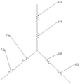
- the six stator coils respectively include: a first coil 131 , a second coil 132 , a third coil 133 , a clockwise direction or a counterclockwise direction along the circumferential direction of the outer ring of the stator, a first coil 131 , a second coil 132 , a third coil 133 , The fourth coil 134 , the fifth coil 135 , and the sixth coil 136 .
- the first coil and the fourth coil are set as U-phase
- the second coil and fifth coil are set as V-phase
- the third coil and sixth coil are set as W-phase
- the included angle between the two coils belonging to the same phase is 180°
- Two coils belonging to the same phase are connected in series to form a branch.
- FIG. 4 is a circuit diagram of a three-phase stator provided by an embodiment of the present disclosure.
- the number of parallel branches in the winding coils belonging to the same phase is 2, that is, the head end of one winding group coil in the same phase is connected to the head end of another winding group coil in the same phase.
- the tail end of one winding coil is connected to the tail end of the other winding coil of the same phase so that two branches are formed, ie the winding coils of the same phase are connected in parallel.
- the six stator coils respectively include: a first coil, a second coil, a third coil, a fourth coil, and a clockwise direction or a counterclockwise direction along the circumferential direction of the outer stator ring 11 .
- Coil, Fifth Coil, Sixth Coil are set as U-phase
- the second coil and the fifth coil are set as V-phase
- the third and sixth coils are set as W-phase
- the two coils belonging to the same phase are separated and connected in parallel to obtain two branches .
- the yoke of the stator is provided with a semicircular hole 112 for positioning the axial diffuser of the fan; the center of the semicircular hole 112 is set on the centerline of the stator teeth.
- FIG. 5 is a schematic exploded view of the structure of a fan provided by an embodiment of the present disclosure.
- the fan includes: the stator 1 and the rotor 2 provided in the foregoing embodiments, and the rotor 2 is a permanent magnet with two poles.
- the fan further includes a circuit board 7 .
- the outgoing terminals of each phase of the stator are connected to the circuit board through lead wires 13A.
- one outlet end of each phase of the coils of the stator is connected to the circuit board 7 after adopting "Y" connection or delta connection, and is connected to the power supply through the circuit board 7 .
- one outgoing terminal of each phase can be connected to the circuit board 7 through the lead 13A.
- the fan also includes: axial diffuser 3, air cover 4 and impeller 5.
- the axial diffuser 3 is fixedly connected to the stator 1, and the axial diffuser 3 includes an outer cylinder 31, a main body 32 arranged in the outer cylinder 31 and connecting the outer cylinder 31 and the main body
- the diffuser vanes 33 of the part 32 divide the annular space between the outer cylinder 31 and the main body 32 into a plurality of diffuser air ducts 34, the main body 32 having a center Axle hole 35.
- the air cover 4 is fixedly connected with the axial diffuser 3, and an impeller chamber 9 and an annular grating-free channel 8 surrounding the impeller chamber are formed between the air cover 4 and the axial diffuser 3.
- the annular grid-free channel communicates with the impeller chamber 9 and the diffuser air duct, and the air mask 4 has an air inlet;
- the impeller 5 is arranged in the impeller chamber 9 , and the impeller 5 is used to introduce air from the air inlet 41 , and is driven by the impeller 5 to enter the expansion chamber through the annular grating-free passage 8 .
- the compressed air duct flows out from the other end of the diffuser air duct.
- the radial diffuser is cancelled, and the axial diffuser 3 is used.
- the flow tends to be stable and the generation of vortices in the flow channel is reduced.
- Radial expansion is canceled. It can effectively reduce wind resistance, reduce energy loss, and improve the working efficiency of the fan. Increase the "dynamic and static gap", so that the "dynamic and static interference” effect of the fan when working is weakened, and the noise of the fan is reduced.
- the radial diffuser is generally provided with axial diffuser vanes at the position of the annular grating-free channel 8 of the present disclosure to form a radial air channel, which is often very close to the vanes. After the air comes out of the impeller 5, it directly hits the radial diffuser. On the leading edge of the blade 33, a strong "dynamic and static interference" occurs. A large number of documents have proved that the "dynamic and static interference" generated by the rotor 2 and stator 1 blades is an important part of the fan noise.
- the fan in the embodiment of the present disclosure cancels the radial diffuser, and adopts the axial diffuser 3 to increase the "dynamic and static gap", which is a very powerful means to improve the noise of the fan.
- the diameter of the fan can be reduced accordingly.
- the problems such as shortening the service life of the bearing 6 and increasing the noise of the fan caused by having to increase the power due to the increase of the diameter of the fan are avoided.
- the outer diameter of the main body 32 of the axial diffuser 3 is equal to the outer diameter of the stator 1 , so that the air flowing out from the diffuser air duct 34 flows through the outside of the stator 1 .
- the outer diameter of the main body 32 of the axial diffuser 3 is equal to the outer diameter of the stator 1 , so that the fluid can flow out from the axial diffuser 3 through the outer ring of the stator 1 without obstacles. Flowing from outside the stator 1 reduces wind resistance and improves fluid efficiency.
- the outer diameter of the main body portion 32 of the axial diffuser 3 is equal to the outer diameter of the stator 1 , not absolutely equal, and a certain error is allowed.
- the error between the two is 1%, 3%, 5%, 7%, 10% and so on.
- one of the axial diffuser 3 and the stator 1 includes a plurality of positioning posts 36
- the other of the axial diffuser 3 and the stator 1 includes a plurality of semicircular holes adapted to the positioning posts 36 . 112.
- the axial diffuser 3 and the stator 1 are respectively provided with positioning posts 36 and semi-circular holes 112 correspondingly to facilitate the connection and fixation of the axial diffuser 3 and the stator 1 .
- the positioning post 36 may be provided on either one of the axial diffuser 3 and the stator 1, and the semicircular hole 112 may be provided on the other.
- the positioning posts 36 may be provided on the axial diffuser 3 while the semicircular holes 112 are provided on the stator 1 .
- the positioning post 36 extends in the axial direction of the axial diffuser 3 .
- some of the diffuser vanes 33 of the diffuser vanes 33 of the axial diffuser 3 extend along the axial direction of the axial diffuser 3 to form the positioning posts 36
- the stator 1 includes the semi-circular holes 112 .
- the number of locating posts 36 is not the same as the number of diffuser vanes 33 . In general, the number of locating posts 36 may be less than the number of diffuser vanes 33 . Therefore, when the positioning column 36 is disposed on the axial diffuser 3 , the positioning column 36 may be formed by extending part of the diffuser vanes 33 in the axial direction.
- 3 diffuser vanes 33 out of 12 diffuser vanes 33 extend in the axial direction to form positioning posts 36 .
- the diffuser vanes 33 extend along the axial direction of the axial diffuser 3 to form the positioning posts 36 , which can make the positioning posts 36 have sufficient strength without affecting the structure of the axial diffuser 3 . And at the same time can reduce the consumption of materials.
- it is avoided that the thickness of the position where the positioning column 36 is located must be increased.
- the ends of the diffuser vanes 33 may integrally extend along the axial direction of the axial diffuser 3 to form the positioning posts 36 . Parts of the ends of the diffuser vanes 33 may also extend in the axial direction of the diffuser 3 to form the positioning posts 36 .
- the partial body of the end of the diffuser vane 33 extends along the axial direction of the diffuser 3 to form the positioning post 36
- the side of the diffuser vane 33 close to the main body 32 can be axially along the diffuser 3 .
- the axial extension of the locating post 36 is formed.
- the positioning posts 36 may be formed on the body portion 32 .
- the locating post 36 may be located on the body portion 32 at a location corresponding to the diffuser vane 33 .
- a positioning post may be partially formed on the body portion 32 and partially extended from the diffuser vanes 33 .
- the semicircular hole 112 may be a hole slot or an open slot.
- a semicircular hole 112 is concavely formed on the outer peripheral surface of the stator 1 .
- the outer peripheral surface of the semicircular hole 112 is concave to form an open groove, which not only ensures stable positioning, but also saves materials while ensuring strength.
- the wall surface of the semicircular hole 112 is a cylindrical surface, and the positioning post 36 has a cylindrical surface matching the wall surface of the semicircular hole 112 .
- the wall surface of the semicircular hole 112 and the corresponding matching surface of the positioning column 36 are cylindrical surfaces, which effectively ensures the stability of the combination of the two.
- the positioning post 36 is a semi-cylindrical body.
- One side of the positioning column 36 has a cylindrical surface matching with the wall surface of the semi-circular hole 112 , and the other side is matching with the peripheral surface of the stator 1 .
- the semicircular hole 112 may be set at any position on the circumferential surface of the stator 1 .
- the semicircular hole 112 is located on the outer peripheral surface corresponding to the tooth centerline of the stator 1 .
- the semicircular holes 112 are provided on the outer peripheral surface opposite to the teeth of the stator 1 . There is enough space for the semicircular hole 112 in this part, and the strength is ensured, and it is not necessary to increase the thickness and other dimensions of the part where the semicircular hole 112 is located, thereby increasing the material consumption.
- the numbers of the semicircular holes 112 and the positioning posts 36 are not specifically limited, for example, they may be 2, 3, 4, and so on.
- a plurality of semicircular holes 112 are distributed on a circumference.
- a plurality of positioning posts 36 are also distributed evenly on a circumference. The diameters of the two circles are the same.
- the semi-circular holes 112 and the positioning posts 36 are evenly distributed on their respective circumferences, and when the axial diffuser 3 and the stator 1 are connected, it is not necessary to limit the two in a specific orientation. Any one of the positioning posts 36 can be matched with any one of the semicircular holes 112 .
- the fixed connection manner between the axial diffuser 3 and the stator 1 is not limited.
- the axial diffuser 3 and the stator 1 may be bonded by glue, or connected by an interference fit, or connected by a threaded member, or the like.
- one or more connecting posts 113 in the axial diffuser 3 and one or more connecting holes 37 in the stator 1 are matched with the connecting posts 113 .
- one or more connecting holes in the axial diffuser 3 , and one or more connecting posts adapted to the connecting holes are arranged in the stator 1 .
- the connecting column 113 is provided in the stator as an example.
- the axial diffuser 3 and the stator 1 are connected together with the connecting hole 37 through the connecting column 113 .
- the connection post 113 and the hole wall of the connection hole 37 are fixedly connected by glue. In this way, glue can be applied in a specific position to avoid defects such as glue overflow.
- the connection post 113 and the connection hole 37 are fixedly connected by interference fit.
- the axial diffuser 3 includes a plurality of connecting holes 37
- the stator 1 includes a plurality of connecting posts 113 that are matched with the connecting holes 37 .
- a plurality of connection holes 37 may be provided on the main body portion 32 .
- the corresponding connecting column 113 and the connecting hole 37 and the corresponding positioning column 36 and the semicircular hole 112 may be included at the same time.
- the circles where the corresponding connecting posts 113 and the connecting holes 37 are located are collinear with the axis lines of the circles where the corresponding positioning posts 36 and the semicircular holes 112 are located.
- the radius of the circle where the corresponding connection post 113 and the connection hole 37 are located may be smaller than the radius of the circle where the corresponding positioning post 36 and the semicircular hole 112 are located.
- the length of the connecting post 113 is less than the length of the positioning post 36 .
- the end surface of the outer cylinder 31 close to the air cover 4 has a first annular protrusion 38, so that the end surface of the outer cylinder 31 forms a first stepped surface, and the outer wall surface of the outer cylinder 31 extends axially to form an annular shape.
- Protrusion; the air mask 4 has a second annular protrusion 42, so that the end face of the air mask 4 connected to the outer cylinder 31 forms a second stepped surface, and the second stepped surface is adapted to the first stepped surface.
- a stepped surface is provided at the part where the outer tube 31 is connected with the air cover 4, which can make the transition of the inner wall surface of the part where the air cover 4 and the outer tube 31 connect more smoothly, and reduce the interference to the fluid.
- the number of blades of the impeller 5 is odd.
- the number of blades of the impeller 5 is 3, 5, 7, 9, 11, and the like.
- the number of blades of the impeller 5 is an odd number, which can reduce asymmetrical injection residual stress and reduce resonance.
- the number of blades of the impeller 5 and the number of the diffuser blades 33 are not multiples of each other.
- the number of the diffuser vanes 33 is selected to be a number that cannot divide the number of vanes of the impeller 5 , so that air noise can be reduced.
- the number of vanes of the impeller 5 is seven, and the number of the diffuser vanes 33 is twelve.
- the number of diffuser vanes 33 is a multiple of three.
- the number of the diffuser vanes 33 is a multiple of 3 to facilitate the positioning of the positioning posts 36 .
- Three positioning columns 36 can ensure the positioning of the axial diffuser 3 and the stator 1 .
- the positioning posts 36 are evenly distributed on the circumference, using the assembly of the axial diffuser 3 and the stator 1 .
- the number of the diffuser vanes 33 being a multiple of 3 can ensure the uniform distribution of the positioning columns 36 .
- the number of diffuser vanes 33 may be, for example, 9, 12, 15, or the like. Of course, in the embodiment of the present disclosure, it is not excluded that the number of diffuser vanes 33 is a number other than a multiple of 3.
- the number of vanes of the impeller 5 is less than the number of the diffuser vanes 33 . While the blades of the impeller 5 meet the suction efficiency, the number of the diffuser blades 33 also meets the rectification efficiency.
- the diffuser vanes 33 may be inclined. That is, the diffuser vanes 33 are not parallel to the axis of the axial diffuser 3 .
- the axis of the diffuser air duct 34 is also not parallel to the axis of the axial diffuser 3 .
- the included angle formed between the axis of the diffuser air duct 34 and the axis of the axial diffuser 3 may be 10°-45°.
- the axial diffuser 3 is assembled on the motor shaft 10 through the bearing 6 .
- the impeller 5 is fixed on the motor.
- the fan in the embodiment of the present disclosure further includes a rotor 2 and a circuit board 7 .
- the rotor 2 is fixed on the motor shaft 10 .
- the circuit board 7 is connected to the stator 1 .
- An embodiment of the present disclosure provides a cleaning apparatus, which includes the blower of any of the foregoing embodiments.
- the fan in the cleaning device cancels the radial diffusion, and adopts the axial diffuser 3 , and the chaotic airflow from the impeller 5 passes through the annular grating-free channel 8 and directly enters the axial diffuser 3 , after the diversion of the diffuser vanes 33 of the axial diffuser 3, the flow tends to be stable and the generation of vortices in the flow channel is reduced.
- Radial expansion is canceled. It can effectively reduce wind resistance, reduce energy loss, and improve the working efficiency of the fan. Increase the "dynamic and static gap", so that the "dynamic and static interference" effect of the cleaning equipment is weakened, and the noise of the fan is reduced.
- the radial diffuser is generally arranged at the position of the annular non-grid channel 8, which is often very close to the blades. After the air comes out of the impeller 5, it directly hits the leading edge of the radial diffuser blade 33, resulting in strong "dynamic and static interference".
- the fan of the cleaning device of the embodiment of the present disclosure cancels the radial diffuser, and adopts the axial diffuser 3 to increase the "dynamic and static gap", which is a very powerful means to improve the noise of the fan.
- the diameter of the fan can be reduced accordingly.
- the problems such as shortening the service life of the bearing 6 and increasing the noise of the fan caused by having to increase the power due to the increase of the diameter of the fan are avoided.
- a cleaning device provided with the blower according to any one of the above technical solutions.
- the cleaning equipment in this embodiment includes a cleaning robot, a hand-held vacuum cleaner, and the like.
Landscapes
- Engineering & Computer Science (AREA)
- Power Engineering (AREA)
- Mechanical Engineering (AREA)
- General Engineering & Computer Science (AREA)
- Microelectronics & Electronic Packaging (AREA)
- Insulation, Fastening Of Motor, Generator Windings (AREA)
Abstract
Description
Claims (15)
- 一种定子,其特征在于,包括:呈圆环状的定子外圈(11);所述定子外圈(11)的内侧的周向上连接有均匀分布的多个定子齿(12);所述定子齿(12)沿着定子外圈(11)的径向设置;每个所述定子齿(12)的外部均缠绕有绕线组线圈(13);每个绕线组线圈(13)均对应设置有绝缘线架(1111),每个所述绝缘线架(1111)设置在定子外圈(11)的轴向上;所述绝缘线架(1111)设置有第一引线槽,所述第一引线槽用于将所述绕线组线圈的一端引出并围绕所述定子外圈(11)的外部的周向上与属于同相的绕线组线圈连接;属于同相的绕线组线圈对应的所述绝缘线架(1111)的第一引线槽的深度相同,不同相的绕线组线圈对应的所述绝缘线架(1111)的第一引线槽的深度彼此不同。
- 根据权利要求1所述的定子,其特征在于,所述定子外圈(11)是通过链式连接的多个呈环扇形的定子单元(111)围成的;每个所述定子单元(111)均连接有所述定子齿(12);每个所述绝缘线架(1111)均设置在所述定子单元(111)上。
- 根据权利要求2所述的定子,其特征在于,所述定子外圈(11)是在所述定子齿(12)完成绕线形成所述绕线组线圈(13)之后,且通过所述绝缘线架(1111)将所述绕线组线圈的一端引出并围绕所述定子外圈(11)的外部的周向延伸且与属于同相的绕线组线圈连接之后,将首位的所述定子单元和尾位的定子单元连接,并对所有相邻的定子单元的连接采用焊接形成。
- 根据权利要求1-3任一项所述的定子,其特征在于,所述定子齿(12)远离所述定子外圈(11)的一端向内凹陷形成圆弧状结构;由所述定子齿(12)的所述圆弧状结构围成的圆用于容纳具有两极的转子;所述定子齿(12)的个数为6;所述定子的相数为三相。
- 根据权利要求4所述的定子,其特征在于,沿着所述定子外圈(11)周向方向依次包括第一绕线组线圈、第二绕线组线圈、第三绕线组线圈、第四绕线组线圈、第五绕线组线圈和第六绕线组线圈;其中第一绕线组线圈的第一端和第四绕线组线圈的一端连接,以形成定子的第一相,第二绕线组线圈的第一端和第五绕线组线圈的一端连接,以形成定子的第二相,第三绕线组线圈的第一端和第六绕线组线圈的一端连接,以形成定子的第三相,以使同一相的两个所述绕线组线圈的夹角为180°。
- 根据权利要求5所述的定子,其特征在于,还包括:卡线部(15),所述卡线部(15)设置在与所述第六绕线组线圈对应的第六绝缘线架的远离所述定子 齿(12)的一侧;所述第六绝缘线架包括第二引线槽,所述第二引线槽用于将每相的出线端引出至所述卡线部,以被卡线部卡持。
- 根据权利要求5或6所述的定子,其特征在于,所述第一绕线组线圈、第三绕线组线圈和第五绕线组线圈对应的绝缘线架均设置有第三引线槽,所述第三引线槽用于将每相的出线端引出;每相的出线端通过引线(13A)连接至电路板上。
- 根据权利要求4-7任一项所述的定子,其特征在于,6个所述绕线组线圈(13)采用“Y”接法或三角形接法连接以形成定子的三相。
- 根据权利要求1-8任一项所述的定子,其特征在于,属于同一相的绕线组线圈(13)支路数为1;或者属于同一相的绕线组线圈(13)中并联的支路数为2。
- 根据权利要求1-9任一项所述的定子,其特征在于,所述定子的轭部设置有用于定位风机的轴向扩压器(3)的半圆孔(112);所述半圆孔(112)设置在所述定子齿(12)的中心线上。
- 根据权利要求10所述的定子,其特征在于,靠近所述轴向扩压器的所述定子外圈(11)的一面,设置有与所述轴向扩压器(3)的连接孔(37)匹配的连接柱(113),所述连接柱(113)用于装配所述轴向扩压器(3)。
- 一种风机,其特征在于,包括转子和如权利要求1-11任一项所述的定子(1);所述转子(2)为具有两极的永磁铁。
- 根据权利要求12所述的风机,其特征在于,还包括电路板(7);所述定子每相的出线端通过引线(13A)连接至所述电路板。
- 根据权利要求11-13任一项所述的风机,其特征在于,还包括:轴向扩压器(3),与所述定子(1)固定连接,所述轴向扩压器(3)包括外筒(31)、设于所述外筒(31)内的主体部(32)和连接所述外筒(31)和所述主体部(32)的扩压器叶片(33),所述扩压器叶片(33)将所述外筒(31)和所述主体部(32)之间的环形空间分隔成多个扩压风道(34),所述主体部(32)具有中心轴孔(35);风口罩(4),其与所述轴向扩压器(3)固定连接,所述风口罩(4)与所述轴向扩压器(3)之间形成叶轮室(9)和环绕所述叶轮室的(9)环形无栅通道(8),所述环形无栅通道连通(8)所述叶轮室(9)和所述扩压风道,所述风口罩(4)具有进风口;叶轮(5),其设于所述叶轮室(9)内,所述叶轮(5)用于将空气从所述进风口(41)引入,并在所述叶轮(5)的驱动下经所述环形无栅通道(8)进入所述扩压风道,并从所述扩压风道的另一端流出。
- 一种清洁设备,其特征在于,包括如权利要求11-14任一项所述的风机。
Priority Applications (4)
| Application Number | Priority Date | Filing Date | Title |
|---|---|---|---|
| US18/022,198 US12199486B2 (en) | 2020-09-14 | 2021-09-03 | Stator, fan, and cleaning device |
| KR1020227036369A KR102800087B1 (ko) | 2020-09-14 | 2021-09-03 | 고정자, 팬 및 청소 장치 |
| EP21865927.4A EP4213343A4 (en) | 2020-09-14 | 2021-09-03 | STATOR, FAN AND CLEANING DEVICE |
| JP2022560953A JP7743431B2 (ja) | 2020-09-14 | 2021-09-03 | ステータ、ファンおよびクリーニング装置 |
Applications Claiming Priority (2)
| Application Number | Priority Date | Filing Date | Title |
|---|---|---|---|
| CN202010963271.2 | 2020-09-14 | ||
| CN202010963271.2A CN114189065A (zh) | 2020-09-14 | 2020-09-14 | 一种定子、风机及清洁设备 |
Publications (1)
| Publication Number | Publication Date |
|---|---|
| WO2022052873A1 true WO2022052873A1 (zh) | 2022-03-17 |
Family
ID=80539317
Family Applications (1)
| Application Number | Title | Priority Date | Filing Date |
|---|---|---|---|
| PCT/CN2021/116434 Ceased WO2022052873A1 (zh) | 2020-09-14 | 2021-09-03 | 一种定子、风机及清洁设备 |
Country Status (6)
| Country | Link |
|---|---|
| US (1) | US12199486B2 (zh) |
| EP (1) | EP4213343A4 (zh) |
| JP (1) | JP7743431B2 (zh) |
| KR (1) | KR102800087B1 (zh) |
| CN (1) | CN114189065A (zh) |
| WO (1) | WO2022052873A1 (zh) |
Cited By (1)
| Publication number | Priority date | Publication date | Assignee | Title |
|---|---|---|---|---|
| CN114865820A (zh) * | 2022-03-23 | 2022-08-05 | 江门市邦特电子电器有限公司 | 一种三相直流无刷电机及电机线方法 |
Families Citing this family (3)
| Publication number | Priority date | Publication date | Assignee | Title |
|---|---|---|---|---|
| KR20220101409A (ko) * | 2021-01-11 | 2022-07-19 | 엘지전자 주식회사 | 모터 조립체용 커넥션링 및 그의 제조방법, 모터 조립체 |
| JP7604927B2 (ja) * | 2021-02-05 | 2024-12-24 | 株式会社デンソー | ステータ、回転電機、ステータの製造方法及び回転電機の製造方法 |
| CN115822877A (zh) * | 2022-11-24 | 2023-03-21 | 昆山岱屹精密机械有限公司 | 风力发电装置及新能源汽车 |
Citations (6)
| Publication number | Priority date | Publication date | Assignee | Title |
|---|---|---|---|---|
| CN102204062A (zh) * | 2008-11-03 | 2011-09-28 | 菲艾姆股份有限公司 | 电机 |
| CN107947398A (zh) * | 2016-10-13 | 2018-04-20 | 福特全球技术公司 | 电机的定子槽构造 |
| CN207753516U (zh) * | 2017-12-21 | 2018-08-21 | 上海海立电器有限公司 | 绝缘支架以及压缩机定子 |
| DE102017209931A1 (de) * | 2017-06-13 | 2018-12-13 | Robert Bosch Gmbh | Elektrische Maschine, Stator für eine elektrische Maschine, sowie Verfahren zur Herstellung eines solchen |
| CN209984154U (zh) * | 2019-01-31 | 2020-01-24 | 稻津电机(珠海)有限公司 | 一种高速吸尘器马达 |
| CN212543466U (zh) * | 2020-09-14 | 2021-02-12 | 北京石头世纪科技股份有限公司 | 一种定子、风机及清洁设备 |
Family Cites Families (14)
| Publication number | Priority date | Publication date | Assignee | Title |
|---|---|---|---|---|
| JP2000232745A (ja) | 1999-02-10 | 2000-08-22 | Toshiba Kyaria Kk | 圧縮機用電動機 |
| JP5468747B2 (ja) * | 2007-06-05 | 2014-04-09 | レスメド・モーター・テクノロジーズ・インコーポレーテッド | 軸受管を有するブロワ |
| JP4957614B2 (ja) * | 2008-03-28 | 2012-06-20 | ダイキン工業株式会社 | ステータ、モータおよび圧縮機 |
| JP2013211956A (ja) * | 2012-03-30 | 2013-10-10 | Mitsubishi Electric Corp | 回転電機 |
| JP5850431B2 (ja) | 2012-12-25 | 2016-02-03 | 三菱電機株式会社 | 電動機用固定子の製造方法 |
| JP2017163726A (ja) * | 2016-03-10 | 2017-09-14 | 日立オートモティブシステムズ株式会社 | 電動流体ポンプ |
| JP6635511B2 (ja) * | 2016-04-08 | 2020-01-29 | マブチモーター株式会社 | ブラシレスモータ |
| JP2018125950A (ja) * | 2017-01-31 | 2018-08-09 | 日本電産株式会社 | モータ及びそれを備えた送風装置 |
| JP6765542B2 (ja) * | 2017-08-29 | 2020-10-07 | 三菱電機株式会社 | モータ及び空気調和装置 |
| JP2018166399A (ja) * | 2018-07-10 | 2018-10-25 | 日立アプライアンス株式会社 | ロータ組立体 |
| CN109185196B (zh) * | 2018-09-30 | 2020-04-10 | 广东威灵电机制造有限公司 | 电风机 |
| DE102019200155A1 (de) * | 2019-01-09 | 2020-07-09 | Robert Bosch Gmbh | Elektromotor |
| CN112136264A (zh) * | 2019-03-13 | 2020-12-25 | 株式会社Top | 旋转机以及绝缘体 |
| KR102888410B1 (ko) * | 2020-07-27 | 2025-11-21 | 삼성전자주식회사 | 모터 어셈블리 및 이를 포함하는 청소기 |
-
2020
- 2020-09-14 CN CN202010963271.2A patent/CN114189065A/zh active Pending
-
2021
- 2021-09-03 WO PCT/CN2021/116434 patent/WO2022052873A1/zh not_active Ceased
- 2021-09-03 US US18/022,198 patent/US12199486B2/en active Active
- 2021-09-03 EP EP21865927.4A patent/EP4213343A4/en active Pending
- 2021-09-03 KR KR1020227036369A patent/KR102800087B1/ko active Active
- 2021-09-03 JP JP2022560953A patent/JP7743431B2/ja active Active
Patent Citations (6)
| Publication number | Priority date | Publication date | Assignee | Title |
|---|---|---|---|---|
| CN102204062A (zh) * | 2008-11-03 | 2011-09-28 | 菲艾姆股份有限公司 | 电机 |
| CN107947398A (zh) * | 2016-10-13 | 2018-04-20 | 福特全球技术公司 | 电机的定子槽构造 |
| DE102017209931A1 (de) * | 2017-06-13 | 2018-12-13 | Robert Bosch Gmbh | Elektrische Maschine, Stator für eine elektrische Maschine, sowie Verfahren zur Herstellung eines solchen |
| CN207753516U (zh) * | 2017-12-21 | 2018-08-21 | 上海海立电器有限公司 | 绝缘支架以及压缩机定子 |
| CN209984154U (zh) * | 2019-01-31 | 2020-01-24 | 稻津电机(珠海)有限公司 | 一种高速吸尘器马达 |
| CN212543466U (zh) * | 2020-09-14 | 2021-02-12 | 北京石头世纪科技股份有限公司 | 一种定子、风机及清洁设备 |
Non-Patent Citations (1)
| Title |
|---|
| See also references of EP4213343A4 * |
Cited By (1)
| Publication number | Priority date | Publication date | Assignee | Title |
|---|---|---|---|---|
| CN114865820A (zh) * | 2022-03-23 | 2022-08-05 | 江门市邦特电子电器有限公司 | 一种三相直流无刷电机及电机线方法 |
Also Published As
| Publication number | Publication date |
|---|---|
| JP2023520799A (ja) | 2023-05-19 |
| US20230307978A1 (en) | 2023-09-28 |
| KR20220158007A (ko) | 2022-11-29 |
| KR102800087B1 (ko) | 2025-04-28 |
| JP7743431B2 (ja) | 2025-09-24 |
| CN114189065A (zh) | 2022-03-15 |
| EP4213343A4 (en) | 2024-10-30 |
| US12199486B2 (en) | 2025-01-14 |
| EP4213343A1 (en) | 2023-07-19 |
Similar Documents
| Publication | Publication Date | Title |
|---|---|---|
| WO2022052873A1 (zh) | 一种定子、风机及清洁设备 | |
| US8106557B2 (en) | Permanent magnet synchronous motor and hermetic compressor | |
| CN212543466U (zh) | 一种定子、风机及清洁设备 | |
| JP2008131813A (ja) | 永久磁石式回転電機,風力発電システム,永久磁石の着磁方法 | |
| US11268532B2 (en) | Electric blower, electric vacuum cleaner, and hand dryer | |
| CN212536158U (zh) | 一种风机及清洁设备 | |
| CN112688522A (zh) | 一种高功率密度轴向磁场永磁电机结构 | |
| CN210724364U (zh) | 一种外转子开关磁阻轮毂电机的冷却装置 | |
| CN101567597A (zh) | 一种单相电容运转电机 | |
| CN108429365A (zh) | 定子组件、电机及压缩机 | |
| CN114183382B (zh) | 一种风机及清洁设备 | |
| US12253090B2 (en) | Fan and cleaning device | |
| CN111987855A (zh) | 定子模块与风扇电机 | |
| CN208142938U (zh) | 定子组件、电机及压缩机 | |
| CN217935209U (zh) | 一种高速风筒无刷电机 | |
| CN217643115U (zh) | 一种电机 | |
| CN113162262B (zh) | 定子铁芯单元、定子铁芯、电机及压缩机 | |
| JP2020129880A (ja) | 電動機及びそれを用いた電動送風機及びそれを用いた電気掃除機 | |
| WO2022193592A1 (zh) | 电机转子以及电机 | |
| CN217904126U (zh) | 电机转子结构、电机和车辆 | |
| CN219477702U (zh) | 转子铁芯及使用该转子铁芯的转子组件和永磁电机 | |
| CN212367091U (zh) | 一种永磁直流变频电机 | |
| CN201388132Y (zh) | 一种定、转子电机 | |
| CN209072164U (zh) | 一种具有配合极数的外转子电机 | |
| CN100536279C (zh) | 一种电机的双柱式磁极 |
Legal Events
| Date | Code | Title | Description |
|---|---|---|---|
| 121 | Ep: the epo has been informed by wipo that ep was designated in this application |
Ref document number: 21865927 Country of ref document: EP Kind code of ref document: A1 |
|
| ENP | Entry into the national phase |
Ref document number: 2022560953 Country of ref document: JP Kind code of ref document: A |
|
| ENP | Entry into the national phase |
Ref document number: 20227036369 Country of ref document: KR Kind code of ref document: A |
|
| WWE | Wipo information: entry into national phase |
Ref document number: 2021865927 Country of ref document: EP |
|
| NENP | Non-entry into the national phase |
Ref country code: DE |
|
| ENP | Entry into the national phase |
Ref document number: 2021865927 Country of ref document: EP Effective date: 20230414 |