WO2022054345A1 - 安全監視装置、安全監視方法、及び、プログラム - Google Patents
安全監視装置、安全監視方法、及び、プログラム Download PDFInfo
- Publication number
- WO2022054345A1 WO2022054345A1 PCT/JP2021/019575 JP2021019575W WO2022054345A1 WO 2022054345 A1 WO2022054345 A1 WO 2022054345A1 JP 2021019575 W JP2021019575 W JP 2021019575W WO 2022054345 A1 WO2022054345 A1 WO 2022054345A1
- Authority
- WO
- WIPO (PCT)
- Prior art keywords
- safety monitoring
- monitoring device
- event
- unit
- safety
- Prior art date
- Legal status (The legal status is an assumption and is not a legal conclusion. Google has not performed a legal analysis and makes no representation as to the accuracy of the status listed.)
- Ceased
Links
Images













Classifications
-
- G—PHYSICS
- G08—SIGNALLING
- G08B—SIGNALLING SYSTEMS, e.g. PERSONAL CALLING SYSTEMS; ORDER TELEGRAPHS; ALARM SYSTEMS
- G08B21/00—Alarms responsive to a single specified undesired or abnormal condition and not otherwise provided for
- G08B21/02—Alarms for ensuring the safety of persons
-
- H—ELECTRICITY
- H04—ELECTRIC COMMUNICATION TECHNIQUE
- H04N—PICTORIAL COMMUNICATION, e.g. TELEVISION
- H04N7/00—Television systems
- H04N7/18—Closed-circuit television [CCTV] systems, i.e. systems in which the video signal is not broadcast
- H04N7/188—Capturing isolated or intermittent images triggered by the occurrence of a predetermined event, e.g. an object reaching a predetermined position
-
- F—MECHANICAL ENGINEERING; LIGHTING; HEATING; WEAPONS; BLASTING
- F16—ENGINEERING ELEMENTS AND UNITS; GENERAL MEASURES FOR PRODUCING AND MAINTAINING EFFECTIVE FUNCTIONING OF MACHINES OR INSTALLATIONS; THERMAL INSULATION IN GENERAL
- F16P—SAFETY DEVICES IN GENERAL; SAFETY DEVICES FOR PRESSES
- F16P3/00—Safety devices acting in conjunction with the control or operation of a machine; Control arrangements requiring the simultaneous use of two or more parts of the body
- F16P3/12—Safety devices acting in conjunction with the control or operation of a machine; Control arrangements requiring the simultaneous use of two or more parts of the body with means, e.g. feelers, which in case of the presence of a body part of a person in or near the danger zone influence the control or operation of the machine
- F16P3/14—Safety devices acting in conjunction with the control or operation of a machine; Control arrangements requiring the simultaneous use of two or more parts of the body with means, e.g. feelers, which in case of the presence of a body part of a person in or near the danger zone influence the control or operation of the machine the means being photocells or other devices sensitive without mechanical contact
- F16P3/142—Safety devices acting in conjunction with the control or operation of a machine; Control arrangements requiring the simultaneous use of two or more parts of the body with means, e.g. feelers, which in case of the presence of a body part of a person in or near the danger zone influence the control or operation of the machine the means being photocells or other devices sensitive without mechanical contact using image capturing devices
-
- G—PHYSICS
- G01—MEASURING; TESTING
- G01S—RADIO DIRECTION-FINDING; RADIO NAVIGATION; DETERMINING DISTANCE OR VELOCITY BY USE OF RADIO WAVES; LOCATING OR PRESENCE-DETECTING BY USE OF THE REFLECTION OR RERADIATION OF RADIO WAVES; ANALOGOUS ARRANGEMENTS USING OTHER WAVES
- G01S17/00—Systems using the reflection or reradiation of electromagnetic waves other than radio waves, e.g. lidar systems
- G01S17/86—Combinations of lidar systems with systems other than lidar, radar or sonar, e.g. with direction finders
-
- G—PHYSICS
- G01—MEASURING; TESTING
- G01S—RADIO DIRECTION-FINDING; RADIO NAVIGATION; DETERMINING DISTANCE OR VELOCITY BY USE OF RADIO WAVES; LOCATING OR PRESENCE-DETECTING BY USE OF THE REFLECTION OR RERADIATION OF RADIO WAVES; ANALOGOUS ARRANGEMENTS USING OTHER WAVES
- G01S17/00—Systems using the reflection or reradiation of electromagnetic waves other than radio waves, e.g. lidar systems
- G01S17/88—Lidar systems specially adapted for specific applications
- G01S17/89—Lidar systems specially adapted for specific applications for mapping or imaging
-
- G—PHYSICS
- G01—MEASURING; TESTING
- G01S—RADIO DIRECTION-FINDING; RADIO NAVIGATION; DETERMINING DISTANCE OR VELOCITY BY USE OF RADIO WAVES; LOCATING OR PRESENCE-DETECTING BY USE OF THE REFLECTION OR RERADIATION OF RADIO WAVES; ANALOGOUS ARRANGEMENTS USING OTHER WAVES
- G01S7/00—Details of systems according to groups G01S13/00, G01S15/00, G01S17/00
- G01S7/48—Details of systems according to groups G01S13/00, G01S15/00, G01S17/00 of systems according to group G01S17/00
- G01S7/4808—Evaluating distance, position or velocity data
-
- G—PHYSICS
- G06—COMPUTING OR CALCULATING; COUNTING
- G06T—IMAGE DATA PROCESSING OR GENERATION, IN GENERAL
- G06T7/00—Image analysis
- G06T7/10—Segmentation; Edge detection
- G06T7/11—Region-based segmentation
-
- G—PHYSICS
- G06—COMPUTING OR CALCULATING; COUNTING
- G06T—IMAGE DATA PROCESSING OR GENERATION, IN GENERAL
- G06T7/00—Image analysis
- G06T7/10—Segmentation; Edge detection
- G06T7/194—Segmentation; Edge detection involving foreground-background segmentation
-
- G—PHYSICS
- G06—COMPUTING OR CALCULATING; COUNTING
- G06V—IMAGE OR VIDEO RECOGNITION OR UNDERSTANDING
- G06V10/00—Arrangements for image or video recognition or understanding
- G06V10/70—Arrangements for image or video recognition or understanding using pattern recognition or machine learning
- G06V10/764—Arrangements for image or video recognition or understanding using pattern recognition or machine learning using classification, e.g. of video objects
-
- G—PHYSICS
- G06—COMPUTING OR CALCULATING; COUNTING
- G06V—IMAGE OR VIDEO RECOGNITION OR UNDERSTANDING
- G06V20/00—Scenes; Scene-specific elements
- G06V20/50—Context or environment of the image
- G06V20/52—Surveillance or monitoring of activities, e.g. for recognising suspicious objects
-
- G—PHYSICS
- G08—SIGNALLING
- G08B—SIGNALLING SYSTEMS, e.g. PERSONAL CALLING SYSTEMS; ORDER TELEGRAPHS; ALARM SYSTEMS
- G08B21/00—Alarms responsive to a single specified undesired or abnormal condition and not otherwise provided for
- G08B21/18—Status alarms
- G08B21/22—Status alarms responsive to presence or absence of persons
-
- G—PHYSICS
- G06—COMPUTING OR CALCULATING; COUNTING
- G06T—IMAGE DATA PROCESSING OR GENERATION, IN GENERAL
- G06T2207/00—Indexing scheme for image analysis or image enhancement
- G06T2207/10—Image acquisition modality
- G06T2207/10028—Range image; Depth image; 3D point clouds
-
- G—PHYSICS
- G06—COMPUTING OR CALCULATING; COUNTING
- G06T—IMAGE DATA PROCESSING OR GENERATION, IN GENERAL
- G06T2207/00—Indexing scheme for image analysis or image enhancement
- G06T2207/30—Subject of image; Context of image processing
- G06T2207/30196—Human being; Person
-
- G—PHYSICS
- G06—COMPUTING OR CALCULATING; COUNTING
- G06T—IMAGE DATA PROCESSING OR GENERATION, IN GENERAL
- G06T2207/00—Indexing scheme for image analysis or image enhancement
- G06T2207/30—Subject of image; Context of image processing
- G06T2207/30232—Surveillance
-
- G—PHYSICS
- G08—SIGNALLING
- G08B—SIGNALLING SYSTEMS, e.g. PERSONAL CALLING SYSTEMS; ORDER TELEGRAPHS; ALARM SYSTEMS
- G08B13/00—Burglar, theft or intruder alarms
- G08B13/18—Actuation by interference with heat, light, or radiation of shorter wavelength; Actuation by intruding sources of heat, light, or radiation of shorter wavelength
- G08B13/189—Actuation by interference with heat, light, or radiation of shorter wavelength; Actuation by intruding sources of heat, light, or radiation of shorter wavelength using passive radiation detection systems
- G08B13/194—Actuation by interference with heat, light, or radiation of shorter wavelength; Actuation by intruding sources of heat, light, or radiation of shorter wavelength using passive radiation detection systems using image scanning and comparing systems
- G08B13/196—Actuation by interference with heat, light, or radiation of shorter wavelength; Actuation by intruding sources of heat, light, or radiation of shorter wavelength using passive radiation detection systems using image scanning and comparing systems using television cameras
- G08B13/19665—Details related to the storage of video surveillance data
- G08B13/19669—Event triggers storage or change of storage policy
-
- G—PHYSICS
- G08—SIGNALLING
- G08B—SIGNALLING SYSTEMS, e.g. PERSONAL CALLING SYSTEMS; ORDER TELEGRAPHS; ALARM SYSTEMS
- G08B13/00—Burglar, theft or intruder alarms
- G08B13/18—Actuation by interference with heat, light, or radiation of shorter wavelength; Actuation by intruding sources of heat, light, or radiation of shorter wavelength
- G08B13/189—Actuation by interference with heat, light, or radiation of shorter wavelength; Actuation by intruding sources of heat, light, or radiation of shorter wavelength using passive radiation detection systems
- G08B13/194—Actuation by interference with heat, light, or radiation of shorter wavelength; Actuation by intruding sources of heat, light, or radiation of shorter wavelength using passive radiation detection systems using image scanning and comparing systems
- G08B13/196—Actuation by interference with heat, light, or radiation of shorter wavelength; Actuation by intruding sources of heat, light, or radiation of shorter wavelength using passive radiation detection systems using image scanning and comparing systems using television cameras
- G08B13/19665—Details related to the storage of video surveillance data
- G08B13/19671—Addition of non-video data, i.e. metadata, to video stream
-
- G—PHYSICS
- G08—SIGNALLING
- G08B—SIGNALLING SYSTEMS, e.g. PERSONAL CALLING SYSTEMS; ORDER TELEGRAPHS; ALARM SYSTEMS
- G08B13/00—Burglar, theft or intruder alarms
- G08B13/18—Actuation by interference with heat, light, or radiation of shorter wavelength; Actuation by intruding sources of heat, light, or radiation of shorter wavelength
- G08B13/189—Actuation by interference with heat, light, or radiation of shorter wavelength; Actuation by intruding sources of heat, light, or radiation of shorter wavelength using passive radiation detection systems
- G08B13/194—Actuation by interference with heat, light, or radiation of shorter wavelength; Actuation by intruding sources of heat, light, or radiation of shorter wavelength using passive radiation detection systems using image scanning and comparing systems
- G08B13/196—Actuation by interference with heat, light, or radiation of shorter wavelength; Actuation by intruding sources of heat, light, or radiation of shorter wavelength using passive radiation detection systems using image scanning and comparing systems using television cameras
- G08B13/19678—User interface
- G08B13/19682—Graphic User Interface [GUI] presenting system data to the user, e.g. information on a screen helping a user interacting with an alarm system
-
- G—PHYSICS
- G08—SIGNALLING
- G08B—SIGNALLING SYSTEMS, e.g. PERSONAL CALLING SYSTEMS; ORDER TELEGRAPHS; ALARM SYSTEMS
- G08B13/00—Burglar, theft or intruder alarms
- G08B13/18—Actuation by interference with heat, light, or radiation of shorter wavelength; Actuation by intruding sources of heat, light, or radiation of shorter wavelength
- G08B13/189—Actuation by interference with heat, light, or radiation of shorter wavelength; Actuation by intruding sources of heat, light, or radiation of shorter wavelength using passive radiation detection systems
- G08B13/194—Actuation by interference with heat, light, or radiation of shorter wavelength; Actuation by intruding sources of heat, light, or radiation of shorter wavelength using passive radiation detection systems using image scanning and comparing systems
- G08B13/196—Actuation by interference with heat, light, or radiation of shorter wavelength; Actuation by intruding sources of heat, light, or radiation of shorter wavelength using passive radiation detection systems using image scanning and comparing systems using television cameras
- G08B13/19678—User interface
- G08B13/19691—Signalling events for better perception by user, e.g. indicating alarms by making display brighter, adding text, creating a sound
Definitions
- the present invention relates to a safety monitoring device, a safety monitoring method, and a program.
- Patent Document 1 uses an object detection sensor to arbitrarily apply various known image processing methods, machine learning-based classifiers, and the like to detect a person.
- the technique described in Patent Document 2 is to obtain the distance between a person and a mobile crane in a three-dimensional space.
- the technique described in Patent Document 2 divides a moving object into a plurality of cubes (cuboids) by depth map data, and subtracts the radius of the circumscribed sphere of each cube from the distance between the center points of the two cubes. The distance between cubes.
- the technique described in Patent Document 2 obtains the minimum value of the combination of distances between all cubes as the shortest distance between objects (the shortest distance between a person and a mobile crane).
- Patent Documents 1 and 2 has been required to have a good grasp of the relationship between a person and an object.
- Patent Document 1 does not describe a specific human detection technology, so that it is not convenient and it is not easy to construct a system. Therefore, the technique described in Patent Document 1 has been required to have a good grasp of the relationship between a person and an object.
- the technique described in Patent Document 2 may not be able to detect a danger even when a person is directly under the crane vehicle, for example, if the distance between the person and the crane vehicle is larger than a predetermined distance. There was sex. In other words, if a person is directly under the mobile crane, it is possible that the person has entered the dangerous area. In this case, even if the distance between the person and the mobile crane is larger than the predetermined distance, it may not be safe. The technique described in Patent Document 2 may be overlooked as unsafe in such a case. Therefore, it has been requested that the technology described in Patent Document 2 have a good grasp of the relationship between a person and an object so that it is not overlooked that it is not safe.
- the present invention has been made in view of the above-mentioned problems of the prior art, and an object of the present invention is a safety monitoring device, a safety monitoring method, and a safety monitoring method capable of satisfactorily grasping the relationship between a person and an object. To provide a program.
- An area setting unit that is a safety monitoring device and can set a plurality of alarm target areas for the detection target area of the safety sensor, and an arbitrary alarm function for each of the alarm target areas.
- a safety monitoring device having an alarm type setting unit capable of setting a type and a moving object recognition analysis unit that recognizes the movement of a moving object based on sensor data measured by the safety sensor.
- the alarm type setting unit has a function of issuing a warning to all moving objects, a function of issuing a warning only to a person, and a distance between a person and a large object larger than a person within a certain distance.
- a function to issue a warning when a person enters a function to issue a warning when a person enters in the direction of travel of the large object, a function to issue a warning only to a moving object having a certain speed or higher, and a moving object having a constant speed or less.
- a function that issues a warning only to a warning a function that combines any two or more functions to obtain a logical sum, or a function that combines any two or more functions to create a logical product.
- the safety monitoring device according to (1) or (2) above, wherein two or more of them can be selected as the type of the alarm function.
- the moving object recognition analysis unit extracts point cloud data representing a moving object from the three-dimensional data measured by the rider as the safety sensor, and creates a bounding box of a size required to enclose the point cloud data. Create and use any one or more or all of the five data of the width, depth and height of the bounding box, as well as the height of the bottom surface and the height of the top surface of the bounding box, as the size of each person.
- the minimum value and the maximum value are determined, and it is a human judgment condition that the size of the moving body is within the determined range, and the size of the moving body continuously meets the judgment condition for a certain period of time arbitrarily determined.
- the safety monitoring device according to any one of (1) to (4) above, which identifies the moving object as a person when the moving object is used.
- the moving object recognition analysis unit uses one or more or all of five data of the width, depth, and height of the bounding box, and the height of the bottom surface and the height of the top surface of the bounding box. , Identifying a large object larger than a person and from the minimum distance between the center of the bottom or top surface of the person's bounding box and each side of the bottom or top surface of the large object's bounding box. The distance obtained by subtracting the radius of the circumscribing circle on the bottom surface or the top surface of the above is calculated as the distance between the person and the large object, and the distance between the person and the large object is smaller than an arbitrarily determined constant distance.
- the safety monitoring device according to (5) above, which issues a warning when the error occurs.
- the moving object recognition analysis unit issues a warning to the above (6) when the time when the distance between the person and the large object becomes smaller than the fixed distance continues for an arbitrarily set fixed time.
- the moving object recognition analysis unit stops the warning when the time when the distance between the person and the large object becomes larger than the fixed distance continues for a certain period or more arbitrarily determined (6). Or the safety monitoring device according to (7).
- the safety monitoring device according to any one of (1) to (11) above, which has a video processing unit that superimposes the position of a moving object detected by the safety sensor on video data.
- an event list includes a record management unit that records and manages video data obtained by capturing all or part of the detection target area in a storage unit, and an event including the alarm data when a warning is issued. It has an event list processing unit that is added to and managed in the event list, and the recording management unit constantly records the video data in the storage unit, and an arbitrary alarm location is designated from the event list.
- the safety monitoring device according to any one of (1) to (12) above, wherein the event list processing unit displays video data for a certain period of time before and after the designated alarm location on the display unit.
- the record management unit has a record management unit that records and manages the video data of the detection target area in the storage unit, and the record management unit has an event to be warned according to the type of the alarm function.
- the safety monitoring device according to any one of (1) to (12) above, which records the video data before and after the base point in the storage unit with the time point of occurrence as the base point.
- the alarm type setting unit can specify a process of detecting the characteristics of the moving object from the video data of the detection target area as the alarm function according to any one of (1) to (15) above.
- the described safety monitoring device can specify a process of detecting the characteristics of the moving object from the video data of the detection target area as the alarm function according to any one of (1) to (15) above.
- the safety monitoring device is one of the above (1) to (17), which notifies the warning data detected by the set alarm function to an external device equipped with a program for performing camera image processing.
- the event list has a recording management unit that divides video data into files at predetermined time intervals and records them in a storage unit, and an event list processing unit that creates and manages an event list that can be selected for each event.
- the processing unit controls not to automatically delete the file containing the video within the video playback time range of the event for the event selected by the safety observer, or saves the file in another area of the storage unit.
- the safety monitoring device according to any one of (1) to (24) above, which performs any of the re-controls.
- the event list processing unit has a function of automatically deleting the file based on a predetermined rule, and the predetermined rule secures a certain amount of free space of the recording means or is constant.
- the safety monitoring device according to (25) above which is either the passage of time.
- the event list processing unit acquires sensor data including one or both of the start time and the end time of the event generated in the detection target area from the safety sensor, and the video reproduction time range of the event list.
- the safety monitoring device according to (25) or (26) above.
- the display screen including the video playback time range of the specified event is displayed on the display unit.
- the event list processing unit starts from a certain time before the start time of the event for which no automatic deletion is selected and the event to which the important mark is added in advance at the timing of selecting whether or not to automatically delete the file.
- the safety monitoring device according to (31) above which controls not to automatically delete a file including a period up to a certain time later.
- the event list processing unit is concerned when the event for which no automatic erasure is selected is selected and changed to with automatic erasure, or when the important mark is removed from the event to which the important mark is added in advance.
- the event list processing unit deletes an event of the file from the event list when automatically deleting a file for which a predetermined time has elapsed since it was recorded, and selects whether or not to automatically delete the file.
- the safety monitoring according to any one of (31) to (33) above, which controls not to delete the event for which no automatic deletion is selected at the timing and the event to which the important mark is added in advance from the event list. Device.
- the safety monitoring unit has a safety monitoring unit that monitors the entry of the object into the monitoring area of the safety sensor, and the safety monitoring unit uses the time when the object enters the monitoring area as the start time of the event.
- the time when the object leaves the monitoring area or a time when a certain time has elapsed from the start time of the event is set as the end time of the event, and the start time and end time of the event are notified to the event list processing unit (25).
- the safety monitoring device according to any one of (34).
- a safety monitoring method including a notification type setting step in which a type can be set, and a moving object recognition analysis step of recognizing the movement of a moving object based on sensor data measured by the safety sensor.
- the relationship between a person and an object can be grasped well.
- L-Shape shape data point cloud data
- FIG. 1 is a configuration diagram of a safety monitoring system S including a safety monitoring device 10 according to the present embodiment.
- FIG. 2 is a configuration diagram of the safety monitoring device 10.
- the safety monitoring system S includes one or more safety monitoring devices 10, one or more riders 51, one or more surveillance cameras 61, and one or more Web terminals 62. I have.
- the safety monitoring device 10 is a device that monitors the safety of the detection target area (measurement space) of the safety sensor.
- the safety monitoring device 10 is composed of a personal computer (PC) or the like.
- the rider 51 is a three-dimensional sensor that is installed around the measurement space to be used as a safety sensor and detects an object.
- the surveillance camera 61 is an imaging unit that is opposed to the periphery of the measurement space and photographs the measurement space. Like the surveillance camera 61z, the surveillance camera 61 may have a setting receiving unit 61a, a setting processing unit 61b, and a notification unit 61c.
- the surveillance camera 61z is an external device equipped with a program (not shown) for processing camera images.
- the setting receiving unit 61a is a means for receiving settings for camera image processing.
- the setting processing unit 61b is a means for executing camera image processing received by the setting reception unit 61a on the video data.
- the setting processing unit 61b may be set so as to determine the safety of the measurement space.
- the notification unit 61c is a means for notifying the safety monitoring device 10 and the Web terminal 62 of the image processed by the camera image and the determination result of the safety of the measurement space.
- the Web terminal 62 is an external device equipped with a program (not shown) for performing camera image processing. In the present embodiment, it is assumed that the Web terminal 62 has the notification acquisition unit 62a.
- the notification acquisition unit 62a is a means for acquiring the safety determination result of the image processed by the camera image and the measurement space from the safety monitoring device 10 and the monitoring camera 61z.
- the safety monitoring device 10 includes a control unit 11, a storage unit 30, and a communication unit 39. Further, the safety monitoring device 10 includes an operation unit 41, a display 42 (display unit), a warning lamp 43, and a speaker 44 (sound alarm unit).
- the control unit 11 includes an area setting unit 12, an alarm type setting unit 13, a video acquisition unit 14, a rider data acquisition unit 15, a moving object recognition analysis unit 16, a result output unit 17, and a video processing unit 18. It has a record management unit 19, a video display processing unit 20, a safety sensor input unit 21, a safety monitoring unit 22, and an event list processing unit 23.
- the area setting unit 12 is a means for setting an area having an arbitrary attribute (for example, a report target area described later, a report exclusion area, etc.) with respect to the detection target area (measurement space) of the rider 51 which is a safety sensor.
- the alerting type setting unit 13 is a means for setting an arbitrary alerting function type for each area.
- the image acquisition unit 14 is a means for acquiring image data in the measurement space.
- the rider data acquisition unit 15 is a sensor data acquisition unit that acquires sensor data from the rider 51 as a safety sensor arranged around the measurement space.
- the moving body recognition analysis unit 16 extracts a moving body from the three-dimensional data based on the sensor data measured by the safety sensor (rider 51 in this embodiment), recognizes the movement of the moving body, analyzes the traveling direction, and issues a warning. It is a means to emit.
- the moving object recognition analysis unit 16 includes a foreground data extraction unit 16a, a clustering processing unit 16b, a bounding box generation unit 16c, an angle smoothing unit 16d, an image recognition unit 16e, and an alarm analysis unit 16f. There is.
- the foreground data extraction unit 16a is a means for extracting foreground data from the input three-dimensional data.
- the clustering processing unit 16b is a means for grouping data based on the degree of similarity between the data in unsupervised learning.
- the bounding box generation unit 16c is a means for generating a bounding box.
- the "bounding box” means the smallest rectangular or rectangular parallelepiped area surrounding an object.
- the angle smoothing portion 16d is a means for performing averaging processing with a predetermined number of frames or a processing method.
- the image recognition unit 16e is a means for recognizing an image from video data.
- the image recognition unit 16e is a means for performing person determination, gender determination, posture determination, and the like by identifying faces.
- the alarm analysis unit 16f is a means for issuing a warning by performing processing according to the type of the alarm function using the result of the moving object detected by the clustering process.
- the result output unit 17 is a means for transmitting a warning issued by detecting a moving object by the moving object recognition analysis unit 16 to the video processing unit 18 as event data.
- the image processing unit 18 is a means for creating a display screen to be displayed on the display 42.
- the video processing unit 18 can perform processing such as superimposing event data on the video data.
- the image processing unit 18 can perform arbitrary camera image processing such as superimposing a human detection frame on a camera image.
- the record management unit 19 is a means for recording and managing video data in a storage unit.
- the image display processing unit 20 is a means for processing a file divided into predetermined time intervals to create an image and displaying it on the display 42.
- the safety sensor input unit 21 is a means for inputting a signal output from a safety sensor such as a rider, a camera, a motion sensor, and a touch sensor.
- the safety monitoring unit 22 is a means for monitoring the entry of an object into the monitoring area.
- the event list processing unit 23 is a means for creating and managing an event list that can be selected for each event.
- the event list includes issue data, custom data, and the like as events.
- the storage unit 30 stores the control program Pr, the setting recording data 31, the video recording data 32, and the processed image data 33.
- the control program Pr is a program that causes the computer to function as the safety monitoring device 10.
- the setting record data 31 is data set in the safety monitoring device 10 via the user interface.
- the video recording data 32 is video data taken by the surveillance camera 61.
- the processed image data 33 is image data obtained by performing arbitrary processing on the video data.
- FIG. 3 is an explanatory diagram of a notification target area and a notification exclusion area.
- the area setting unit 12 of the safety monitoring device 10 sets the alarm target area and the alarm exclusion area for the detection target area (measurement space).
- the detection target area is a measurement space in which an object is measured by the rider 51.
- the detection target area is an area in which the movement of a moving object existing within the detectable range of the rider 51 is monitored by the safety monitoring device 10.
- the area subject to notification is an area where an event is issued (warning is issued) when an intruder is detected.
- An event is data indicating that a warning has been issued.
- the safety monitoring device 10 continues to issue a warning while an intruder is present in the alarm target area. Further, the safety monitoring device 10 does not issue a warning even if it detects a moving object outside the alarm target area. Multiple reporting areas can be set.
- the setting of the alarm target area is valid only within the detection target area. When the alarm target area is set to overlap with the alarm exclusion area, the alert exclusion area has priority, so that the safety monitoring device 10 does not issue a warning.
- the alert exclusion area is an area where an event is not issued (warning issuance) even if an intruder is detected.
- the alert exclusion area is specified when the detection of moving objects is intentionally excluded from the monitoring target.
- the safety monitoring device 10 detects an intruder and issues an event (warning issuance) even if it is within the detection target area or the alarm target area, as long as it is within the range designated as the alarm exclusion area. Do not do. For example, if there is a tree in the detection target area and there is a possibility that the tree will be erroneously detected as an intruder due to the tree shaking due to the wind, the area around the tree can be set as the alarm exclusion area.
- the safety monitoring device 10 can prevent erroneous detection. Multiple notification exclusion areas can be set.
- the area setting unit 12 can set a plurality of alarm target areas for one detection target area (measurement space).
- two alarm target areas A61a and A61b are set for the detection target area (measurement space) indicated by the alternate long and short dash line.
- only one alarm exclusion area A62 is set, but the area setting unit 12 sets a plurality of alarm exclusion areas for one detection target area (measurement space). be able to.
- the place where the walking path R11 and the alarm exclusion area A62 overlap is set as the exclusion place B62. Then, a portion where the walking path R11 and the alarm target area A61a overlap and do not overlap with the alarm exclusion area A62 is set as the alert location B61a. Further, a portion where the walking path R11 and the alarm target area A61b overlap is set as the alarm location B61b.
- the safety monitoring device 10 issues an event (warning issuance) when a person enters or is entering the warning points B61a and B61b.
- FIGS. 4A to 4C show an example of area setting.
- 4A to 4C are explanatory views of the display screen 100 of the safety monitoring device 10, respectively.
- the safety monitoring device 10 displays the display screen 100 on the display 42 and accepts the setting of the area by the safety monitoring person.
- the "safety observer" means a person who monitors the safety of each measurement space by the safety monitoring device 10.
- the display screen 100 is configured to include a 3D viewer unit 101, a setting unit 102, a rider selection unit 103, an alarm target area tab 104, and the like.
- the 3D viewer unit 101 is a column for displaying an image of the measurement space taken by the surveillance camera 61 and an image processed by processing the image.
- the setting unit 102 is a column for making various settings such as an area and a type of alarm function.
- the rider selection unit 103 is an instruction unit that selects three-dimensional data (distance measuring data) acquired by an arbitrary rider 51.
- the notification target area tab 104 is a tab for setting the notification target area.
- the screen of the alert target area tab 104 includes a block tab 104a, a valid check box 104b, an area selection unit 104c, a display color setting unit 104d, and the like.
- the block tab 104a is a tab for setting the specifications of the bounding box to be added to the object to be notified.
- the "bounding box” means the smallest rectangular or rectangular parallelepiped area surrounding an object.
- the valid check box 104b is a field for designating that a bounding box is added to the object to be notified.
- the area selection unit 104c is a column for selecting an area to be set as a notification target area.
- the display color setting unit 104d is a column for setting the alarm target area frame 101a (see FIG. 4C) displayed on the 3D viewer unit 101.
- the safety observer selects (designates) an arbitrary area with the area selection unit 104c, and the safety monitoring device 10 sets the selected area as the alarm target area. At this time, the safety monitoring device 10 changes the color of the alarm target area frame 101a (see FIG. 4C) displayed on the 3D viewer unit 101 to the color set by the display color setting unit 104d.
- the safety monitoring device 10 has various types of alarm functions.
- a case where the safety monitoring device 10 uses the following three types of alarm functions will be described as an example.
- FIG. 5 is an explanatory diagram showing an example of the area.
- FIG. 6 is an explanatory diagram showing an example of selection of an alarm function by a user interface.
- the first area is an empty area. Therefore, the safety observer can set an arbitrary alarm function for the first area according to the operation. Therefore, for example, the safety observer can set "(1) approach detection” for the first area and set the first area so that all moving objects are targeted for detection.
- the second area is a forklift workshop, which is a dangerous area when people enter. Therefore, the safety observer sets "(2) Entry detection (person)" for the second area.
- the third area is a crane work site, which is an area where it is dangerous for a person to approach the crane by a certain distance R or less. Therefore, the safety observer sets "(3) Proximity detection" for the third area in order to issue a warning to a person who is closer than a certain distance R from the crane.
- the display screen 100 (see FIG. 4A) of the safety monitoring device 10 has a configuration in which one of these three types of alarm functions can be selected by the setting unit 102. Further, the display screen 100 (see FIG. 4A) of the safety monitoring device 10 has a configuration in which a plurality of alarm target areas (no entry areas) can be selected, and each area can be independently set as an area of an arbitrary attribute. ..
- FIG. 7 is an explanatory diagram showing an example of the point cloud data of the bus and the bounding box.
- FIG. 8 is an explanatory diagram showing an example of the coordinates and configuration of the bounding box.
- FIG. 9 is an explanatory diagram showing an example of the bottom surface of the bounding box.
- 10A to 10C are explanatory views of a method for obtaining a rectangle of the (x, z) plane which is the bottom surface of the bounding box, respectively.
- FIG. 7 shows an example of a point cloud data (L-Shape shape data) of a bus measured by a rider 51 and a rectangular bounding box formed so as to surround the point cloud data.
- FIG. 8 shows an example of the coordinates and configuration of a rectangular parallelepiped bounding box formed along the three-dimensional shape of the bus.
- the horizontal plane is (x, z) and the height direction is the y coordinate.
- a bounding box consists of the smallest rectangular or rectangular parallelepiped area that surrounds an object.
- the length of the bottom surface in the long direction is defined as the width W
- the length in the narrow direction is defined as the depth D
- the length from the bottom surface to the top surface is defined as the height H.
- FIG. 9 shows an example of the bottom surface of a bus bounding box arranged at an angle with respect to the X axis.
- the angle formed with the X axis is shown as an angle ⁇ .
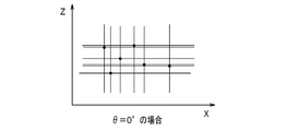
- FIGS. 10A to 10C show a method for obtaining a rectangle of the (x, z) plane which is the bottom surface of the bounding box, respectively.
- the pixel points indicated by black circles represent each pixel of the clustered point cloud.
- FIGS. 10A to 10C first, a straight line with a slope of an angle ⁇ is drawn through each black circle pixel point, and the outermost straight line is defined as two straight lines in the X-axis direction of the bounding box at an angle ⁇ .
- a straight line with an angle ⁇ + 90 ° is drawn passing through each black circle pixel point, and the outermost straight line is defined as two straight lines in the Z-axis direction of the bounding box at the angle ⁇ .
- the rectangle surrounded by these four straight lines is used as a bounding box at an angle ⁇ .
- FIG. 11 is an explanatory diagram showing an example of a bounding box.
- FIG. 12 is an explanatory diagram showing an example of determination conditions for a person (Person) and a large object (Large Object).
- FIG. 13A is an explanatory diagram showing an example of an attribute (in the case of a large object) considering the classification result of the detected moving object and the continuity.
- FIG. 13B is an explanatory diagram showing an example of an attribute (in the case of a person) considering the classification result of the detected moving object and the continuity.
- the safety monitoring device 10 detects the moving body 105 with the rider 51, and a bounding box in the shape of a rectangular parallelepiped region (rectangular parallelepiped region) so as to just surround the moving body 105 (surround it with the minimum volume). Generate a 105 box.
- the safety monitoring device 10 determines from the size (width, depth, height) of the bounding box 105 box whether the moving body 105 surrounded by the bounding box 105 box is a human being or a large object larger than a human being. The determination is performed based on, for example, the determination conditions shown in FIG.
- the height H is the distance from the upper surface to the lower surface of the bounding box 105box.
- the height Ht is the distance from the ground G to the upper surface of the bounding box 105box.
- the height Hb is the distance from the ground G to the lower surface of the bounding box 105box.
- Width W Range from a minimum value of 0.3 [m] to a maximum value of 1.2 [m].
- Depth D A range from a minimum value of 0.2 [m] to a maximum value of 1.0 [m].
- Height H Range from a minimum value of 0.5 [m] to a maximum value of 2.3 [m].
- Height Ht Range from a minimum value of 0.5 [m] to a maximum value of 3.0 [m].
- Height Hb Range from minimum value -1.0 [m] to maximum value 0.8 [m].
- all the values of each item are in the following range in the width W, depth D, height H, Ht, and Hb of the moving body 105 reflected in a certain frame in a series of video data. If it is inside, this moving body 105 is classified as a "person".
- the safety monitoring device 10 is, for example, when the respective values of the width W, depth D, height H, Ht, and Hb of the moving body 105 meet the determination conditions of the "large object" shown below. ,
- the moving body 105 is classified as a "large object".
- the following range is only an example and can be changed depending on the operation. (Judgment condition for "large object")
- all of the items are equal to or more than the minimum value of "person", and one or more items are equal to or more than the maximum value of "person”. ..
- the values of each item are the following first conditions and second conditions in the width W, depth D, height H, Ht, and Hb of the moving body 105 of a certain frame (bounding box 105 box). When the condition is satisfied, the moving body 105 is classified as a "large object”.
- First condition All values of each item must meet the following conditions. 0.3 [m] ⁇ width W 0.2 [m] ⁇ depth D 0.5 [m] ⁇ height H 0.5 [m] ⁇ height Ht -1.0 [m] ⁇ height Hb (Second condition)
- the value of any one or more items satisfies the following conditions. 1.2 [m] ⁇ width W 1.0 [m] ⁇ depth D 2.3 [m] ⁇ height H 3.0 [m] ⁇ height Ht 0.8 [m] ⁇ height Hb
- the safety monitoring device 10 determines that the moving body 105 does not meet the judgment conditions of a person and the judgment conditions of a large object in each of the items of width W, depth D, height H, Ht, and Hb of the moving body 105. Is classified as unknown (other).
- the safety monitoring device 10 preferably has a large threshold value in consideration of the case where a plurality of people are detected as one object. Further, the safety monitoring device 10 may preferably set a large threshold value in consideration of a case where the moving body 105 appears to float from the ground, such as when only the upper body of a person is visible.
- the safety monitoring device 10 can be classified into three types, "person”, “large object”, and “unknown (other)” for each frame.
- the moving object detected by the rider 51 may be split or its size may fluctuate during the clustering process due to variations in measurement. Therefore, a large object may momentarily become a human-sized mass. This can result in large objects being classified as "humans”. Therefore, for example, as shown in FIG. 13A, the safety monitoring device 10 preferably sets the attribute of the moving body 105 to "a large object (large moving body)" when the size of the moving body 105 is continuously maintained for a plurality of frames arbitrarily determined. ) ”. Thereby, the safety monitoring device 10 can prevent a large object from being classified as a "person”.
- the safety monitoring device 10 classifies the attribute of the moving body 105 into a "large object (large moving body)" when the size of the moving body 105 is maintained for three consecutive frames. After that, the safety monitoring device 10 maintains the attribute of the moving body 105 as a "large object (large moving body)” unless the frames of another attribute (for example, "person") size are continuous for three frames.
- a moving body 501 classified as a "human” may momentarily become a mass larger than a human (or a mass smaller than a human) due to the influence of some noise.
- the attributes of the moving body 501 should be reviewed only when a plurality of arbitrarily determined frames (for example, 3 frames) are continuous. You should do it.
- the time of one frame is 0.1 seconds, so three frames correspond to 0.3 seconds.
- the case where three frames are continuous has been described, but the optimum number of frames may be selected according to the site.
- the safety monitoring device 10 provides a warning target area (entry prohibited area) within the measurement range of the rider 51, and warns only when the moving object 501 identified as a "person" enters the notification target area. It may be emitted.
- FIG. 14 is a flowchart showing an operation at the time of detecting / issuing a person.
- step S101 the safety observer operates the safety monitoring device 10 while looking at the display screen 100 (see FIG. 4A) to set an area having an arbitrary attribute for the measurement space.
- the area setting unit 12 of the safety monitoring device 10 sets one or more alarm target areas and one or more alarm exclusion areas for one measurement space.
- step S102 the safety observer operates the safety monitoring device 10 while looking at the display screen 100 (see FIG. 4A) to specify the type of the alarm function for each alarm target area.
- the alarm type setting unit 13 of the safety monitoring device 10 sets the type of the alarm function for each alarm target area.
- the safety observer operates the safety monitoring device 10 to instruct the safety monitoring device 10 to start monitoring the measurement space.
- step S103 the video acquisition unit 14 of the safety monitoring device 10 acquires video data of each measurement space from each monitoring camera 61.
- step S105 the rider data acquisition unit 15 of the safety monitoring device 10 acquires ranging data ( ⁇ (i), ⁇ (j), R) as three-dimensional data (sensor data) from the rider 51.
- step S110 the foreground data extraction unit 16a of the motion recognition analysis unit 16 of the safety monitoring device 10 extracts the foreground data from the three-dimensional data by the background subtraction method. That is, the foreground data extraction unit 16a extracts the foreground data by calculating (three-dimensional data-reference background data).
- step S115 the clustering processing unit 16b of the moving object recognition analysis unit 16 of the safety monitoring device 10 obtains a mass of point cloud data (moving object) from the foreground data based on the distance data of the point cloud detected by the three-dimensional data. Extract and perform clustering processing.
- step S120 the bounding box generation unit 16c of the moving object recognition analysis unit 16 of the safety monitoring device 10 creates a rectangular parallelepiped region necessary for surrounding the clustered point cloud data (moving object) mass. Create a bounding box.
- step S125 the alarm analysis unit 16f of the moving object recognition analysis unit 16 of the safety monitoring device 10 determines whether or not the moving object conforms to the human determination condition based on the size (width, depth, height) of the bounding box. To confirm. When it is confirmed that the moving object conforms to the determination condition of a person, the alarm analysis unit 16f adds (sets) a flag (human flag) representing the person to the moving object. As a result, the safety monitoring device 10 recognizes a person with respect to the moving object.
- step S130 the alarm analysis unit 16f of the moving object recognition analysis unit 16 of the safety monitoring device 10 detects the size of the same moving object in the next frame. Then, when the size of the moving body continuously matches the size of the person for the specified number of frames, the alarm analysis unit 16f sets the attribute of the moving body to "person".
- step S135 the alarm analysis unit 16f of the motion recognition analysis unit 16 of the safety monitoring device 10 checks whether or not the motion has entered the alert target area. Then, when there is a moving object that has entered and the attribute of the moving object that has entered is "human", the alarm analysis unit 16f issues a warning.
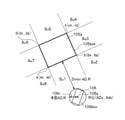
- FIG. 15 is an explanatory diagram showing an example of the distance between a “person” and a “large object” as seen from above.
- the safety monitoring device 10 can obtain (calculate) the distance between the classified "person” and the "large object” as follows.
- the safety monitoring device 10 sets the circumscribed circle surrounding the bounding box 106 box in the area of the person 106.
- the coordinates of the center point 106o of the bounding box 106box of the person 106 can be expressed as (ADx, ADz). Then, the radius of the circumscribed circle surrounding the bounding box 106box is set to AD_R.
- the bottom surface of the large object 105a is a rectangle with four points a, b, c, and d as vertices.
- the safety monitoring device 10 is a distance between the line segment ab of the large object 105a and the center point 106o of the person 106, a distance between the line segment bc of the large object 105a and the center point 106o of the person 106, and the large object 105a.
- the distance between the line segment cd and the center point 106o of the person 106 and the distance between the line segment da of the large object 105a and the center point 106o of the person 106 are obtained (calculated), respectively.
- the safety monitoring device 10 sets the minimum value of each obtained (calculated) value as the distance Dmin between each line segment ab, bc, cd, da and the center point 106o of the person 106.
- the safety monitoring device 10 can obtain (calculate) the distance between the person 106 and the large object 105a by (Dmin-AD_R).
- the safety monitoring device 10 calculates the distance of all combinations between the detected all people 106 and the large object 105a in each frame, and issues a warning when the calculated distance is shorter than the specified threshold distance. It is good to set it to.
- the safety monitoring device 10 may issue different types of warnings according to the calculated distance. For example, when the calculated distance is the following threshold distances Th1, Th2, Th3 (not shown), the following warning can be issued.
- the threshold distances Th1, Th2, Th3 have a relationship of Th1>Th2> Th3.
- the safety monitoring device 10 sets the level as a caution level when (Dmin-AD_R) ⁇ Th1. In this case, the safety monitoring device 10 lights the warning lamp 43 in yellow.
- the safety monitoring device 10 sets the level as the warning level when (Dmin-AD_R) ⁇ Th2. In this case, the safety monitoring device 10 turns on the warning lamp 43 in red.
- the safety monitoring device 10 sets the level as a dangerous level when (Dmin-AD_R) ⁇ Th3. In this case, the safety monitoring device 10 causes the warning lamp 43 to blink red and the speaker 44 to sound an alarm sound.
- FIG. 16 is a flowchart showing an operation at the time of detecting / issuing a report of a person and a large object.
- step S121 A point in which the determination process of step S121 is performed after step S120.
- step S125 A point at which the process proceeds to step S125 when the determination in step S121 determines "Yes”.
- step S121 When the determination in step S121 is "No", the safety monitoring device 10 performs the processes of steps S145 and S150.
- step S135 is deleted, and instead, the process of step S155 is performed after step S130 or step S150. Except for these differences, the operation at the time of detecting / issuing a person and a large object shown in FIG. 16 and the operation at the time of detecting / issuing a person shown in FIG. 14 are the same.
- step S121 the alarm analysis unit 16f of the motion recognition analysis unit 16 of the safety monitoring device 10 determines whether or not the object is a person. If it is determined in step S121 that the object is a person (in the case of "Yes"), the process proceeds to step S125. In this case, the processes from step S125 to step S130 are performed in the same manner as the operation at the time of detecting / issuing a person as shown in FIG. After step S130, the process proceeds to step S155.
- step S121 determines whether the object is a human (in the case of "No"). If it is determined in step S121 that the object is not a human (in the case of "No"), the process proceeds to step S145.
- step S145 the alarm analysis unit 16f of the moving object recognition analysis unit 16 of the safety monitoring device 10 confirms that the moving object conforms to the determination condition of a large object from the size (width, depth, height) of the bounding box. Then, a flag representing a large object (large object flag) is added (set) to the moving object. As a result, the safety monitoring device 10 recognizes a large object with respect to the moving object.
- step S150 the alarm analysis unit 16f of the moving object recognition analysis unit 16 of the safety monitoring device 10 detects the size of the same moving object in the next frame. Then, when the size of the moving body continuously meets the determination condition of the large object for the specified number of frames, the alarm analysis unit 16f sets the attribute of the moving body to "large object". After step S150, the process proceeds to step S155.
- step S155 the alarm analysis unit 16f of the motion recognition analysis unit 16 of the safety monitoring device 10 checks whether or not a motion object has entered the alert target area. Then, when both the "person” and the “large object” enter the alarm target area, the alarm analysis unit 16f measures the distance between the "person” and the “large object", and the distance is determined. When it is shorter than a certain distance, it issues a warning that the "person” has become dangerous.
- FIG. 17 is an explanatory diagram showing an example of a warning screen when the person 106 detected by the rider 51 enters the alarm target area (entry prohibited area) of the camera image.
- the safety monitoring device 10 projects the three-dimensional data acquired from the rider 51 onto the two-dimensional video data (camera video) acquired from the surveillance camera 61.
- the safety monitoring device 10 is set so that the positional relationship between the three-dimensional data and the video data matches. Then, as shown in FIG. 17, the safety monitoring device 10 detects a moving object, adds a bounding box 106 box to the moving object, and recognizes the moving object as a person 106 based on the size of the bounding box 106 box.
- the safety monitoring device 10 uses the color of the bounding box 106 box of the person 106 in the camera image to issue a warning when the person 106 enters the area subject to the notification (no entry area). May be changed to red, or a red frame may be superimposed on the part of the corresponding person 106.
- the safety monitoring device 10 can be configured to constantly record (record) the video data (camera video) acquired from the surveillance camera 61 in the storage unit 30. Such a safety monitoring device 10 can create a warning list by recording the video data (camera video) at the moment when the warning is issued without erasing it. In this case, the safety monitoring device 10 can specify and reproduce (display on the display 42) the video data (camera image) at the time of issuing the alarm for the required time based on the alarm list.
- the safety monitoring device 10 can be configured to operate as shown in FIG. 18A or FIG. 18B, for example. 18A and 18B are operation explanatory views of the safety monitoring device 10.
- the safety monitoring device 10 acquires the three-dimensional data (distance measuring data) measured by the rider 51 by the rider data acquisition unit 15.
- the rider data acquisition unit 15 outputs the acquired three-dimensional data (distance measurement data) to the moving object recognition analysis unit 16.
- the alarm analysis unit 16f detects a moving object based on the alarm function designated for each area. Then, the alarm analysis unit 16f determines whether or not any area is in a situation where a warning should be issued. When there is an area to issue a warning, the moving object recognition analysis unit 16 outputs a lighting instruction signal to the warning lamp so that the lamp is turned on according to the warning level. In response to this, the warning lamp turns on the lamp.
- the warning lamp may be composed of a plurality of lamps and may be specified for each area.
- the moving object recognition analysis unit 16 outputs the result of detecting the moving object to the video processing unit 18 via the result output unit 17.
- the video processing unit 18 creates a display screen 100 (see FIG. 4A) to be displayed on the display 42.
- the image processing unit 18 may perform arbitrary camera image processing such as superimposing a human detection frame on the camera image.
- the safety monitoring device 10 may be configured to include an image recognition unit 18a for camera image processing in the image processing unit 18.
- the image recognition unit 18a determines the person, gender, posture, etc. by face identification for the person recognized by the moving object recognition analysis unit 16 based on the video data (camera image) taken by the surveillance camera 61. I do.
- the safety monitoring device 10 can make a more detailed determination of the danger level.
- the safety monitoring device 10 preferably has a function of smoothing the bounding box.
- FIG. 19 is an operation explanatory diagram of the safety monitoring device 10.
- the safety monitoring device 10 outputs the three-dimensional data (distance measuring data) acquired from the rider 51 by the rider data acquisition unit 15 to the moving object recognition analysis unit 16.
- the foreground data extraction unit 16a takes the difference between the three-dimensional data (distance measuring data) which is the input data and the background data acquired in advance, and extracts the foreground data.
- the clustering processing unit 16b extracts point cloud data with a certain mass from the foreground data and sets it as a moving object candidate. Then, the clustering processing unit 16b verifies the continuity with all the frames from the point cloud data set as the moving object candidate, regards the continuous object as the moving object, and allocates the ID. After that, the bounding box generation unit 16c generates a bounding box for the point cloud data regarded as a moving object.
- the angle ⁇ between the frames in the (x, z) plane of the bottom surface of the created bounding box is a discrete value for each ⁇ . Therefore, the angle smoothing portion 16d performs averaging processing with a predetermined number of frames or a processing method. At that time, the safety observer may be able to change the number of frames, the processing method, and the like by the operation unit 41.
- the safety monitoring device 10 simultaneously displays the video data (camera video) and the bounding box obtained as the point cloud data on the display 42. Therefore, the safety monitoring device 10 can show the safety observer to the extent that the approximate outer shape can be visually seen by the bounding box even in the portion behind the rider 51 where there is no point cloud data.
- FIG. 20 is an explanatory diagram showing an example of angle smoothing processing.
- the angle ⁇ that can be obtained is discretely one of 0 °, 6 °, 12 °, 18 °, ..., 78 °, and 84 °.
- an example in which the angle ⁇ gradually bends from 6 ° to 12 ° is shown.
- the angles ⁇ are mixed at 6 ° and 12 ° due to the variation of the point cloud. The movement of the bounding box in such a state looks like a rattling visually.
- the average angle shown in FIG. 20 is the angle of the calculation result in the above equation (1).
- the average angle shown in FIG. 20 is the angle of smooth change. Therefore, the movement of the bounding box is stable in appearance and relatively close to the movement of an actual moving object (for example, a bus). However, for example, since the angle data between the past 4 frames and the current frame is used, the movement of the bounding box is slightly delayed. The movement of the bounding box can be improved in smoothness by increasing the number of smoothed frames, but the responsiveness is reduced. Therefore, it is better to select the number of smooth frames according to the circumstances of the moving object to be detected. For example, buses and trucks are unlikely to make sudden turns, so a large number of frames may be selected, and a car with many small turns such as a forklift may be selected with a small number of frames.
- FIG. 21 is an explanatory diagram showing an example of angle smoothing processing, as in FIG. 20.
- FIG. 20 shows an example of the case of obtaining by the simple average formula of 5 frames
- FIG. 21 shows the case of obtaining by the weighted average formula of 5 frames weighted by the following formula (2).
- An example is shown.
- the weighted average formula is a formula that emphasizes the current frame.
- ⁇ ave (i) (1 x ⁇ (i-4) + 2 x ⁇ (i-3) + 3 x ⁇ (i-2) + 4 x ⁇ (i-1) + 5 x ⁇ (i)) ⁇ 15 ... (2) )
- FIG. 22 is an explanatory diagram showing a setting example of the angle smoothing process.
- FIG. 22 shows an example in which the operation unit 41 is operated to set the averaging process by using a graphical user interface (GUI) (not shown).
- GUI graphical user interface
- the display screen is configured so that the setting of "Yes” or "No” to execute the angle smoothing process can be set by the radio button. Further, the display screen is configured so that the angle smoothing process can be set when the aspect ratio (wise / depth) of the moving object is less than a certain value. Further, the display screen is configured so that it can be set to perform the angle smoothing process when the size (width) of the object to be implemented is less than a certain size. The larger the value of the size (wise) of the object to be implemented is set, the more frequently the angle smoothing unit 16d performs the angle smoothing process on the moving body.
- the display screen is configured so that it can be set to perform angle smoothing processing when the number of averaged frames is less than a certain number. In the illustrated example, 5 frames are selected as the average number of frames, but this value can be freely changed. In addition, the display screen is configured so that either a simple average or a weighted average can be selected with a radio button.
- the angle smoothing portion 16d performs the angle smoothing process by the simple average, but the angle smoothing process may be performed by the weighted average. Further, the safety monitoring device 10 may perform the angle smoothing process and the center coordinate smoothing process at the same time by using a graphical user interface (not shown). Further, the safety monitoring device 10 may be provided with a graphical user interface which is not shown independently of the angle.
- the safety monitoring device 10 may be configured to constantly record (store in the storage unit 30) video data (camera video) acquired from the monitoring camera 61 and erase it after a certain period of time has elapsed.
- FIG. 23 is an operation explanatory diagram of such a safety monitoring device 10.
- the safety monitoring device 10 converts the video data (camera video) acquired from the monitoring camera 61 into manageable data such as MxPEG by the video processing unit 18 and outputs the data to the recording management unit 19. ..
- the record management unit 19 divides the converted data into files (file data) at predetermined time intervals and records them in a storage means (storage unit 30 or an external recording medium (not shown) so that the database can be managed. Further, the record management unit 19 acquires a file from the video processing unit 18 based on the instruction of the safety observer, and outputs the acquired file to the video display processing unit 20. Further, the recording management unit 19 reads out a file of a specified time from the file group recorded in the storage means (storage unit 30 or an external recording medium (not shown)) and outputs the file to the video display processing unit 20. .. The video display processing unit 20 creates an image based on the file and displays it on the display 42.
- the safety monitoring device 10 acquires a detection signal of an object in the measurement space from the safety sensor 50 such as a rider, a camera, a motion sensor, and a touch sensor by the safety sensor input unit 21, and transmits the detection signal to the safety monitoring unit 22. Output.
- the safety monitoring unit 22 detects the entry of a person, the entry of a dangerous object, or the like based on the detection signal, and issues an event. That is, the safety monitoring unit 22 monitors the entry of the object into the monitoring area of the safety sensor 50. Then, the safety monitoring unit 22 outputs the event to the event list processing unit 23.
- the safety monitoring unit 22 sets the time when the object enters the monitoring area of the safety sensor 50 as the start time of the event, and sets the time when the object leaves the monitoring area or the time when a certain time elapses from the start time of the event. Set as the end time. Then, the safety monitoring unit 22 notifies the event list processing unit 23 of the start time and the end time of the event.
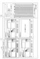
- the event list processing unit 23 creates and updates the event list, and displays, for example, the display screen 110 shown in FIG. 24 on the display 42.
- FIG. 24 is an explanatory diagram showing an example of the display screen 110.
- the display screen 110 has a configuration in which an image of each measurement space taken by the surveillance camera 61 and an updated event list are arranged at the same time.
- the safety observer operates the operation unit 41 while looking at the display screen 110.
- the event list processing unit 23 edits the event according to the operation of the safety observer.
- the display screen 110 has a configuration in which a video display unit 111 for displaying video is arranged on the left side and an event list display unit 112 for displaying an event list is arranged on the right side. There is.
- the video display unit 111 is divided into four screens.
- the safety monitoring device 10 is configured to be able to connect up to four surveillance cameras 61, and displays the video acquired from each surveillance camera 61 on an arbitrary screen of the video display unit 111.
- the safety monitoring device 10 may use the four screens of the video display unit 111 properly according to the operation. For example, the safety monitoring device 10 displays the live image from the surveillance camera 61 on the upper left screen of the image display unit 111, and displays the recorded / reproduced image from the storage means on the upper right screen of the image display unit 111. May be good.
- the safety monitoring device 10 is configured so that the video related to each event of the event list displayed on the event list display unit 112 can be reproduced on the video display unit 111.
- the safety observer selects an event to be played from the event list displayed on the event list display unit 112, double-clicks it with the mouse, or drags it to the screen to be played on the video display unit 111. ..
- the safety monitoring device 10 reproduces the video related to the selected event on the video display unit 111.
- FIG. 25 is an explanatory diagram showing an example of the event list.
- the event list 120 has an important mark column 121, a time stamp column 122, a camera name column 123, a type column 124, and an explanatory column 125 from the left.
- the important mark column 121 is a column to which an important mark indicating that it is an important event is added.
- the important mark has a star shape, but the shape of the important mark is not limited to the star shape and can be any shape.
- the time stamp column 122 is a display column for the start time of the event.
- the camera name column 123 is a display column for the name of the camera that captured the image.
- the type column 124 is a display column for the type of event (Intruder, CUSTOM, etc.).
- the explanation column 125 is a display column for explaining the event.
- the event list 120 can be configured to display the end time of the event, the cause of the event, and the like.
- the event list 120 is configured so that the important mark can be turned on / off by clicking the important mark column 121 of any event with the mouse.
- the safety observer plays the video of an arbitrary event, checks the video, and determines that an incident (important event) has occurred in the video being played, the important mark column for that event. An important mark is added to 121.
- the safety monitoring device 10 stores the video related to the event to which the important mark is added so as not to be erased.
- the safety monitoring device 10 edits the event by allowing the safety monitoring person to arbitrarily select one event from the event list 120 and perform an editing operation on the event editing screen 130 shown in FIG. 26. It can be carried out.
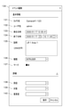
- FIG. 26 is an explanatory diagram showing an example of the event editing screen 130.
- the event editing screen 130 has a camera name column 131, a user name column 132, an occurrence date / time column 133, an end date / time column 134, an explanation column 135, a type column 136, a mark column 137, a cause column 138, and countermeasures. It is configured to include column 139 and importance column 140.
- the camera name column 131 is a display column for the name of the camera that captured the image.
- the user name field 132 is a user name display field.
- the occurrence date / time column 133 is a display column for the occurrence date / time of the event.
- the end date / time column 134 is a display column for the end date / time of the event.
- the explanation field 135 is an input field for explaining the event.
- the type field 136 is an input field for an event type (Intruder, CUSTOM, etc.).
- the mark column 137 is a display column for the type of important mark.
- the cause column 138 is an input field for the cause of the incident that has occurred.
- the countermeasure column 139 is an input field for countermeasures against an incident that has occurred.
- the importance column 140 is an input field for the importance of the incident that has occurred.
- the event editing screen 130 shown in FIG. 26 has contents that reflect the detailed data of the event to which the important mark shown in FIG. 25 is added.
- the event occurrence date / time (start time) displayed in the occurrence date / time column 133 is 12:05:41 on January 17, 2020.
- the end date and time (end time) of the event displayed in the end date and time column 134 is 12:11:20 on January 17, 2020.
- the safety observer may take a certain time (for example, 10 seconds before and after) longer than the event occurrence date / time (start time) and end date / time (end time).
- the safety observer edits the event occurrence date / time column 133 and the end date / time column 134 on the event edit screen 130, sets the event occurrence date / time to 12:05:31 on January 17, 2020, and sets the event. It is advisable to set the end date and time to 12:11:30 on January 17, 2020, and play the video.
- the fixed time for example, 10 seconds before and after applied to the change of the date and time can be arbitrarily changed.
- the safety observer can edit the occurrence date and time (event start time) of the occurrence date and time column 133 and the end date and time (event end time) of the end date and time column 134 from the event edit screen 130.
- the safety monitoring device 10 can limit the end time of the event to the time up to "the start time of the event + the longest time of the event" by setting the maximum time of the event.
- the safety monitoring device 10 can be configured to operate as follows. For example, a monitoring area is set in the rider 51 in advance, the time when a person enters the monitoring area is set as the event occurrence date and time (start time), and the time when the person leaves the monitoring area is set as the event end date and time (end time). And. Then, the safety monitoring device 10 can acquire the event occurrence date / time data and the event end date / time data from the rider 51 at the time of event registration, and can record and manage the acquired date / time data in the storage unit 30.
- the safety monitoring device 10 can limit the end time of the event to the time up to "the start time of the event + the longest time of the event" when the moving object stays in the monitoring area for a long time. Further, the safety monitoring device 10 may be configured so that other items can be edited from the event editing screen 130. Further, the safety monitoring device 10 may be configured so that an event can be newly created by playing back a video of an arbitrary time by using the event editing screen 130.
- FIG. 27 is an explanatory diagram showing an example of a format for storing video data in a storage means.
- FIG. 27 shows an example of using SQLite, which is one of the open source relational database management systems (RDBMS), for file management.
- SQLite which is one of the open source relational database management systems (RDBMS), for file management.
- a database management file called "archive.db” is created under the "Video folder", and a date folder indicating the date (for example, "2020/1/17 folder") is created.
- “2020/1/18 folder”, “2020/1/19 folder”, etc. are created one by one every day.
- Video_20200117_000000.mp4 is a video data file for 10 minutes from 0:00:00 on January 17, 2020.
- video_20200117_001000.mp4 is a video data file for 10 minutes from 0:10:00 on January 17, 2020.
- it is assumed that the video data file is created at intervals of 10 minutes in this way.
- 144 files of "24 hours x (6 files / 1 hour)" are created per day.
- the safety monitoring device 10 uses a large-capacity HDD (Hard Disk Drive) as a recording means (storage unit 30 or an external recording medium (not shown), the recorded data can be constantly stored for about 30 days. can.
- HDD Hard Disk Drive
- the safety monitoring device 10 constantly stores the recorded data (video data file) for 30 days, and once a day, the recorded data (video) for one day exceeding 30 days after recording. Data file) is automatically deleted. At this time, the safety monitoring device 10 automatically deletes the event that has been issued for more than 30 days from the event list.
- the safety monitoring device 10 saves the recorded data (video data file) related to the event to which the important mark shown in FIGS. 25 and 26 is added without erasing it. ..
- the recorded data whose time stamp shown in FIG. 25 is 12:05:41 on January 17, 2020 is automatically set when the retention period of 30 days is exceeded, unless the important mark is added. Is erased.
- the important mark is added to the recorded data whose time stamp shown in FIG. 25 is 12:05:41 on January 17, 2020. Therefore, this recorded data continues to be stored without being erased even at the timing of automatic erasure (that is, even if the storage period after recording exceeds 30 days).
- the event corresponding to the recorded data to which such an important mark is added is left without being deleted from the event list.
- the safety monitoring device 10 When the safety monitoring device 10 automatically erases the recorded data once a day, the safety monitoring device 10 checks the events with the important mark, obtains the playback time of the event with the important mark, and records the recorded data (video) including the time. Save the data file) without erasing it.
- the safety monitoring device 10 has a time stamp of 12:05:41 on January 17, 2020 with respect to the recorded data whose time stamp shown in FIG. 25 is 12:05:41 on January 17, 2020. Recorded data (video data data) including 31 seconds to 12:11:30 shall be saved without being erased.
- the recorded data including from 12:05:31 to 12:11:30 on January 17, 2020 are two files, "Video_20200117_120000.mp4" and “Video_20200117_121000.mp4".
- the safety monitoring device 10 leaves two files related to the event to which the important mark is added even when the recorded data is automatically deleted, and automatically deletes the other files.
- the important mark is turned off (deleted) from the event by subsequent editing
- the recorded data will be automatically deleted after that. It will be erased.
- the event for which the important mark is turned off (deleted) is also deleted from the event list.
- the safety monitoring device 10 has an area setting unit 12 capable of setting a plurality of alarm target areas for the detection target area of the safety sensor, and each alert. It has an alarm type setting unit 13 that can set an arbitrary alarm function type for the target area, and a moving object recognition analysis unit 16 that recognizes the movement of the moving object based on the sensor data measured by the safety sensor. It is configured.
- various management such as areas where heavy machinery (for example, cranes) work, areas where work vehicles such as forklifts move around, areas where all moving objects should not enter for vibration suppression and security, etc. Area is assumed.
- such various management areas are set as notification target areas, and a plurality of such management areas can be set for the detection target area of the safety sensor.
- the safety monitoring device 10 can set an arbitrary type of alarm function for each alarm target area. That is, the safety monitoring device 10 can independently set different alarm functions for each of the plurality of alarm target areas. Therefore, the safety monitoring device 10 can realize an optimum monitoring method. Further, the safety monitoring device 10 can satisfactorily grasp the relationship between a person and an object.
- the safety monitoring device 10 is a sensor data acquisition unit (rider data acquisition) that acquires three-dimensional data (distance measuring data) as sensor data from the rider 51 as a safety sensor. It has a part 15).
- the moving object recognition analysis unit 16 may be configured to extract moving objects from the detection target area based on three-dimensional data and detect the progress of the moving object to each reporting target area.
- the safety monitoring device 10 By using a safety sensor (for example, a rider 51) capable of measuring three-dimensional data, the safety monitoring device 10 according to the present embodiment can set a plurality of areas with measurement accuracy under the same conditions. Therefore, the safety monitoring device 10 can secure stable detection accuracy. Further, when the condition to be monitored changes, the safety monitoring device 10 can respond only by changing the area setting without physically changing the sensor such as reattachment.
- a safety sensor for example, a rider 51
- the alarm type setting unit 13 of the safety monitoring device 10 preferably has a function of issuing a warning to all moving objects, a function of issuing a warning only to a person, and more than a person to a person.
- a function that issues a warning when the distance between a large object and a large object is within a certain distance a function that issues a warning when a person enters in the direction of travel of the large object, and a warning only for moving objects at a certain speed or higher.
- a function that issues a warning a function that issues a warning only to moving objects below a certain speed, a function that combines any two or more functions to create a logical sum, and a combination of any two or more functions.
- any two or more of them may be configured to be selectable as the type of the alarm function.
- the safety monitoring device 10 can use various types of alarm functions depending on the operation. For example, in an area where a heavy machine (for example, a crane) moves, it is preferable to issue a warning when a person and the heavy machine approach each other. Further, in an area where a work vehicle such as a forklift moves, it is preferable to monitor the area so that the worker does not enter. Further, in an area where heavy machinery or the like running on a rail moves, it is preferable to issue a warning when a person enters in the traveling direction. Further, in an area where all moving objects should not enter for vibration suppression, security, etc., it is preferable to monitor the movement of all moving objects.
- a heavy machine for example, a crane
- a work vehicle such as a forklift moves
- the safety monitoring device 10 can realize suitable warning issuance in such an area.
- the condition for issuing a warning is a logical product condition of a person and a large object (for example, a car) at a certain speed or higher, so that the safety monitoring device 10 has a speed limit for the large object (for example, a car). It can be set to issue a warning when entering the area beyond. Further, by setting the condition for issuing a warning as a logical sum condition of the speed between a person and a large object, the safety monitoring device 10 can be set to issue a warning when the large object enters the area.
- the type of the alarm function may be configured to be able to be specified for each area via the user interface.
- the safety monitoring device 10 can realize an environment in which settings can be arbitrarily and easily changed via a user interface.
- the moving object recognition analysis unit 16 of the safety monitoring device 10 is a point cloud data representing a moving object from three-dimensional data measured by a rider 51 as a safety sensor.
- a bounding box of the size required to enclose the point cloud data, the width, depth and height of the bounding box, as well as the height of the bottom surface and the height of the top surface of the bounding box.
- the safety monitoring device 10 By detecting a person from the size of the bounding box, the safety monitoring device 10 according to the present embodiment can perform detection by a simple method without using a known image processing method or machine learning-based method. ..
- the point cloud data of the moving body measured by the rider 51 is subjected to clustering processing and processed as one mass (object).
- a large object for example, a car
- it may not be stably recognized as one object, but may be divided into a plurality of lumps and recognized. be.
- the size of one split mass may be the same as the size of a person. Therefore, if the attributes of a moving object are simply determined based on the size of the person, there is a possibility that a large object will be misidentified as a person.
- the safety monitoring device 10 the state in which a large object is divided into a plurality of lumps and recognized is often resolved in a short period of time, so that the size of the moving body (lump) is the size of a person.
- the moving body (lump) can be determined as a person. Even if such a safety monitoring device 10 misidentifies a large object as a person based on the size of the moving body (lump), the moving body (lump) depends on both the size of the moving body (lump) and the duration of the size. By determining whether or not) is a person, it is possible to greatly reduce the misidentification of a large object as a person.
- the safety monitoring device 10 is set on the condition that the height of the bottom surface of the bounding box is equal to or less than a certain height. Further, since the safety monitoring device 10 according to the present embodiment is about 2 m even if the height of the person is high, it is determined that the person is not a person if the height of the upper surface of the bounding box is higher than a certain height arbitrarily determined. By doing so, it is possible to prevent a moving object other than a human being from being mistakenly recognized as a human.
- the safety monitoring device 10 Since the safety monitoring device 10 according to the present embodiment detects a person by the size of the bounding box, it is possible to include moving objects other than humans by adjusting this size.
- the safety monitoring device 10 can adjust the size of the bounding box so as to include a person with luggage, a plurality of people in a mass, a small car, an object carried by a crane, and the like. Is.
- the moving object recognition analysis unit 16 of the safety monitoring device 10 has a width W, a depth D and a height H of the bounding box, and a height Hb of the bottom surface of the bounding box. And any one or all of the five data of height Ht on the top surface are used to identify large objects larger than humans. Then, as shown in FIG. 15, the moving object recognition analysis unit 16 minimizes the distance between the center point 106o of the bottom surface or the top surface of the bounding box 106 box of a person and each side of the bottom surface or the top surface of the bounding box 105 box of a large object.
- the distance (Dmin-AD_R) obtained by subtracting the radius of the circumscribed circle on the bottom surface or the top surface of the bounding box of a person from the value is calculated as the distance between the person and the large object, and the distance between the person and the large object is arbitrary.
- a warning may be issued when the distance becomes smaller than the fixed distance specified in.
- the moving object recognition analysis unit 16 of the safety monitoring device 10 may calculate the distance using the bottom surface (or the top surface) of each bounding box. As shown in FIG.
- the moving object recognition analysis unit 16 obtains the distance from the center to each line segment of the bottom surface of the bounding box 105 box of a large object with reference to the center point 106o of the bottom surface of the bounding box 106 box of a person, and the minimum thereof.
- the distance (Dmin-AD_R) obtained by subtracting the radius of the circumscribed circle at the bottom of the bounding box 106 box of a person from the value is calculated as the distance between the person and a large object.
- the safety monitoring device 10 calculates the distances of all combinations between a plurality of people and large objects existing in the alarm target area (no entry area), and the distances of those combinations become smaller than a certain distance. A warning can be issued at that time.
- Such a safety monitoring device 10 does not overlook the danger even when a dangerous object is hung above the head of a person such as the above-mentioned crane car and the danger is easily overlooked. In addition, it is possible to monitor without omission.
- the motion recognition analysis unit 16 of the safety monitoring device 10 has an arbitrary time when the distance between a person and a large object becomes smaller than a certain distance. It may be configured to issue a warning when it continues for a certain period of time specified in.
- the safety monitoring device 10 can prevent a large number of warnings from being continuously issued by issuing a warning when the warning is continued for a certain period of time.
- the motion recognition analysis unit 16 of the safety monitoring device 10 may be configured to stop the warning when the distance between a person and a large object becomes larger than a certain distance.
- the safety monitoring device 10 may stop warning when the distance between a person and a large object becomes larger than a certain distance.
- the moving object recognition analysis unit 16 of the safety monitoring device 10 warns when the time when the distance between a person and a large object becomes larger than a certain distance continues for a certain time or more arbitrarily determined. May be configured to stop.
- the safety monitoring device 10 may stop warning when the time when the distance between a person and a large object becomes larger than a certain distance continues for a certain time or more arbitrarily determined.
- the motion recognition analysis unit 16 of the safety monitoring device 10 may be configured to change the alarm level according to the distance between a person and a large object.
- Such a safety monitoring device 10 may change the warning level such as attention level, warning level, danger level, etc. according to the approach distance when a person approaches an object, for example. can.
- the safety monitoring device 10 changes the warning lamp from yellow to red when the warning level changes from the caution level to the warning level, and further changes the warning level from the warning level to the danger level.
- the speaker 44 may sound an alarm sound (buzzer sound).
- the moving object recognition analysis unit 16 of the safety monitoring device 10 may be configured to calculate the speed of the moving object from the distance that the center position of the bounding box has moved in a certain time.
- the safety monitoring device 10 has the timing at which the moving body enters the area by specifying the speed of the moving body from the distance that the center position of the bounding box has moved for a certain time (for example, 0.5 seconds). Can be grasped.
- the safety monitoring device 10 may be configured to include a video processing unit 18 that superimposes the position of a moving object detected by a safety sensor (for example, a rider 51) on video data.
- a safety sensor for example, a rider 51
- Such a safety monitoring device 10 is dangerous, for example, when a moving object is a person to be warned, by superimposing a warning mark as a position of the moving object on the person concerned. Can be visually recognized by the safety observer promptly. As a result, the safety observer can take some measures promptly.
- the safety monitoring device 10 includes a record management unit 19 that records and manages video data obtained by photographing all or a part of a detection target area in a storage unit 30. It has an event list processing unit 23 that adds and manages an event including the alert data to the event list when a warning is issued.
- the record management unit 19 constantly records video data in the storage unit 30. Then, when an arbitrary alarm location is designated from the event list, the safety monitoring device 10 displays video data for a certain period of time before and after the alert location designated by the event list processing unit 23 (display unit). ) May be displayed.
- the safety monitoring device 10 records and saves the time when the warning is issued so that the safety observer can grasp the behavior of the person to whom the warning is issued so that the reproduction location can be specified. Create an event list. Then, by designating an arbitrary event, the safety monitoring device 10 can reproduce the video data of the time before and after the designated event. As a result, the safety observer can confirm the degree of danger by confirming the video data of the time before and after corresponding to the designated event. This also allows the safety observer to provide on-site workers with risk prediction education.
- the event list processing unit 23 of the safety monitoring device 10 issues alert data (events including alert data) for each type of the event list displayed on the display 42 (display unit). May be configured so that can be filtered and displayed.
- the safety monitoring device 10 can filter and display the alert data (events including the alert data) for each type. Therefore, for example, if the safety monitoring device 10 extracts only the function of issuing a warning only to a person as filtering, the recorded data suitable for the condition can be easily extracted. Further, the safety monitoring device 10 can facilitate the work of confirming the video data by the safety observer by managing and storing the alert data (events including the alert data) for each issue type. .. Further, the safety monitoring device 10 can limit the recording of the camera image to, for example, only when an alarm is generated. Further, the safety monitoring device 10 can selectively record a certain period of time before and after the alarm function according to the type of the alarm function, thereby reducing the storage capacity. Further, the safety monitoring device 10 can facilitate the confirmation work of the video data by the safety monitor by managing and storing the video data for each issue type.
- the safety monitoring device 10 has a record management unit 19 that records and manages video data in a detection target area in a storage unit 30.
- the record management unit 19 stores video data before and after the base point, with the time point at which the event to be warned occurs as the base point, according to the type of the alarm function. It may be configured to record in.
- the safety monitoring device 10 records video data before and after the base point in the storage unit 30 with the time point at which the event to be warned occurs as the base point. Therefore, the safety monitoring device 10 can manage the video data for each event that has occurred. Further, by managing and storing the video data for each event that has occurred, the safety monitoring device 10 can facilitate the work of confirming the video data by the safety monitor.
- the alarm type setting unit 13 of the safety monitoring device 10 may be configured to be able to specify a process of detecting the characteristics of a moving object from the video data of the detection target area as the alarm function.
- the safety monitoring device 10 may be configured to be capable of designating a process for detecting the characteristics of a moving object from video data.
- the safety monitoring device 10 can acquire minute features of a moving object such as human face recognition and gender from the image acquired from the camera as an alarm function. Since such a safety monitoring device 10 can set conditions for determining the attributes of a moving object in detail, it is possible to improve the detection accuracy of the attributes of an object.
- the safety monitoring device 10 may be configured to include any one of person identification by face recognition, gender determination, and posture determination as a process for detecting a moving object.
- the safety monitoring device 10 can set the conditions for determining the attributes of the moving object in detail, the accuracy of detecting the attributes of the object can be improved.
- the safety monitoring device 10 is an external device (Web terminal 62, surveillance camera 61z, etc.) equipped with a program for performing camera image processing on the warning data detected by the set alarm function. It may be configured to notify to.
- the external device may manage events and video data independently of the operation of the safety monitoring device 10. Further, it may be easier to manage the event and the video data if the program executed by the safety monitoring device 10 and the program for displaying the camera image have different configurations. Therefore, the safety monitoring device 10 according to the present embodiment may be configured to notify the warning data detected by the set alarm function to an external device equipped with a program for performing camera image processing. As a result, the safety monitoring device 10 can cause, for example, an external device to perform camera image processing, and cause the external device to create an image in which the image of the warning data is superimposed on the camera image.
- the safety monitoring device 10 converts the position data (three-dimensional data) of the moving object detected by the safety monitoring device 10 into the two-dimensional data of the camera image, and the position of the camera image and the position of the image of the warning data. It is advisable to have an external device create an image so as to correspond to.
- the safety monitoring device 10 may be configured to have a smoothing means (angle smoothing portion 16d) for smoothing the angle of the bounding box.
- the safety monitoring device 10 When a bounding box is generated every frame (for example, every 0.1 seconds), the obtained angle ⁇ varies due to the variation of the distance measurement data, and as a result, the distance between two objects (for example, between a person and a car) is calculated. There is a possibility that the variation will be large when requesting. Therefore, the safety monitoring device 10 according to the present embodiment can stabilize the change in the angle ⁇ with the movement of the vehicle by smoothing the angle of the bounding box by the smoothing means (angle smoothing portion 16d). Therefore, the safety monitoring device 10 can stably obtain the distance between two objects (for example, between a person and a car). Further, the safety monitoring device 10 can display an image of visually natural movement when displaying an image of a moving object on the display 42 (display unit).
- the safety monitoring device 10 has a video processing unit 18 that processes three-dimensional data according to the type of the alarm function. As shown in FIGS. 19 to 22, the video processing unit 18 of the safety monitoring device 10 according to the present embodiment may be configured to simultaneously display the point cloud data and the bounding box on the display 42 (display unit).
- the safety monitoring device 10 displays the point cloud data after the clustering process and the bounding box at the same time, so that the safety monitor can see what kind of point cloud the actual measurement data is. Can be visually recognized. Further, in the unlikely event that an accident occurs, the safety monitoring device 10 allows the safety observer to visually recognize the point cloud data of the accident site and the bounding box at the same time, so that the safety observer can easily grasp the situation of the accident site. Can be made to.
- the smoothing means (angle smoothing portion 16d) of the safety monitoring device 10 may be configured to smooth the angle of the bottom surface of the bounding box. ..
- the smoothing means (angle smoothing portion 16d) of the safety monitoring device 10 may be configured to smooth the angle of the bottom surface of the bounding box.
- the safety monitoring device 10 can obtain the angle with an appropriate amount of calculation by smoothing the discrete angles of the bottom surface of the bounding box. Therefore, the safety monitoring device 10 can reduce the amount of calculation and shorten the calculation time.
- the amount of calculation at the time of generating the bounding box is determined by the number of point clouds and the number of repetitions of the calculation by the discrete angle ⁇ . Further, the calculation time is determined by the performance of the CPU (central processing unit) of the personal computer (PC) constituting the safety monitoring device 10.
- the angle of the bottom surface of the bounding box calculated discretely by the smoothing means (angle smoothing portion 16d) of the safety monitoring device 10 according to the present embodiment is determined via the user interface. It may be configured to be arbitrarily changeable.
- the safety monitoring device 10 prepares a user interface so as to be able to determine the optimum discrete angle ⁇ with respect to the angle ⁇ of the bottom surface of the bounding box, and selects the value of the discrete angle ⁇ , for example. be able to.
- either one or both of the smoothing method and the smoothing time value of the smoothing means (angle smoothing portion 16d) of the safety monitoring device 10 according to the present embodiment is set. It may be configured to be arbitrarily changed via the user interface.
- Angle smoothing is performed using past data from the present time.
- the safety monitoring device 10 can select, for example, a method of simply performing averaging, a method of performing weighted averaging with a large weighting closer to the current time, and the like.
- the safety monitoring device 10 can perform an angle smoothing process suitable for the three-dimensional data input from the rider 51. It should be noted that smoothing a large amount of data can improve the smoothness of the image, but the responsiveness of the calculation to changes in the input data is reduced. Therefore, the safety monitoring device 10 may be configured so that a suitable time can be selected according to the input data in consideration of responsiveness.
- the smoothing means (angle smoothing portion 16d) of the safety monitoring device 10 may be configured to smooth the center coordinates of the bottom surface of the bounding box.
- the point cloud data varies from frame to frame. Therefore, not only the angle but also the center coordinates of the bounding box (the center coordinates of the rectangle on the bottom surface) vary. Smoothing the center coordinates of the bounding box is effective in suppressing the variation. Therefore, the smoothing means (angle smoothing portion 16d) of the safety monitoring device 10 according to the present embodiment may be configured to smooth the center coordinates of the bottom surface of the bounding box. Although the center coordinates of the bounding box have been described here as the center coordinates of the rectangle on the bottom surface, the center coordinates of the bounding box can be processed as the center coordinates of the rectangular parallelepiped region (rectangular region). In this case, smoothing the center point of the rectangular parallelepiped region (rectangular region) is also effective.
- the safety monitoring device 10 has a record management unit 19 that divides video data into files at predetermined time intervals and records them in a storage unit 30, and a record management unit 19 for each event. It has an event list processing unit 23 that creates and manages a selectable event list. The event list processing unit 23 controls not to automatically delete the file containing the video within the video playback time range of the event for the event selected by the safety observer, or puts the file in another area of the storage unit 30. It may be configured to perform any of the control to save again.
- the safety monitoring device 10 has data that shows the video reproduction time range in each event, and a file (recorded data) to be reproduced from the video can be specified from the data. Then, the safety monitoring device 10 is configured to determine whether or not it is a file (recorded data) in which an incident (important event) has occurred, and if it is determined that it should be left, select no automatic erasure. ing. As a result, even if the safety monitoring device 10 is set to automatically delete the file (recorded data) based on the determined rule, the safety monitoring device 10 does not delete the file in which the incident (important event) has occurred. Can be managed. Such a safety monitoring device 10 can accumulate data on similar incidents by leaving a file in which an incident (important event) has occurred, and can make a safety observer consider accident prevention measures. ..
- the event list processing unit 23 of the safety monitoring device 10 has a function of automatically deleting a file based on a predetermined rule.
- the predetermined rule may be configured to either secure a certain amount of free space in the recording means (storage unit 30 or an external recording medium (not shown)) or allow a certain period of time to elapse.
- the safety monitoring device 10 can automatically delete the file based on a predetermined rule.
- the safety monitoring device 10 manages so that a certain amount of free space can be secured in a configuration in which the capacity of the HDD as a recording means is fully utilized. Better. Further, in the configuration in which the safety monitoring device 10 automatically erases the file after a certain period of time within a range in which the capacity of the HDD as a recording means has a margin, it is clear how long the data remains. Since it is easy to manage the data, it may be used properly according to the purpose.
- the event list processing unit 23 of the safety monitoring device 10 includes one or both of the start time and the end time of the event generated in the detection target area from the safety sensor.
- the configuration may be such that the sensor data is acquired and the video reproduction time range of the event list is determined.
- the safety monitoring device 10 can reproduce a file (video data) within a video reproduction time range determined for each event, the file (video data) for a suitable time can be reproduced. Can be played.
- the safety monitoring device 10 can set, for example, the time when a person enters the warning issuing area as the start time of the event and the time when the person leaves the warning issuing area as the end time of the event list. Such a safety monitoring device 10 can manage whether or not a person who has entered the dangerous area has evacuated from the dangerous area to the safe area.
- the safety monitoring device 10 according to the present embodiment may be configured to be capable of recording one or both data of the start time and the end time of the event, depending on the intended use.
- the event list processing unit 23 of the safety monitoring device 10 has a function of additionally registering an arbitrary event that has occurred in the past as a new event in the event list. It may have a configuration.
- the safety monitoring device 10 can additionally register any event that has occurred in the past as a new event at the discretion of the safety observer. For example, even if an event has been overlooked by the safety monitoring device 10 in the past, it is determined that an incident (important event) has occurred by the safety observer looking at the image of the file left in the recording means. In this case, the safety monitoring device 10 can additionally register the incident as a new event in the event list. In this case, the safety monitoring device 10 leaves the file (recorded data) in which the incident (important event) has occurred without erasing it.
- the event list processing unit 23 of the safety monitoring device 10 may be configured to have a function of editing the start time and end time of the event.
- the safety monitoring device 10 can arbitrarily edit the start time and end time of the event (that is, the reproduction start time and the reproduction end time of the file related to the event). For example, if an incident (important event) occurs before a person enters the dangerous area, or if a person who enters the dangerous area leaves the dangerous area, the dangerous situation continues to occur. A case is assumed. In such a case, the safety monitoring device 10 can leave the file in that time zone by changing the start time and / or the end time of the event.
- the safety monitoring device 10 has a video processing unit 18 that processes the video data in the detection target area according to the type of the alarm function.
- the video processing unit 18 of the safety monitoring device 10 creates a display screen for simultaneously displaying the video and the event list on the display 42 (display unit), and the safety observer.
- the display 42 may display the image including the image reproduction time range of the specified event.
- the safety monitoring device 10 can reproduce the video of an arbitrary event based on the event list.
- the safety observer can efficiently check the degree of danger at the site by watching the reproduced video.
- the safety monitoring device 10 can easily manage the event and work efficiency such as event display operation and event editing. Can be improved.
- the event list has an important mark for selecting whether or not to automatically delete the file via the graphical user interface. It may be configured so that it can be added for each.
- the safety monitoring device 10 can add an important mark for each event. Therefore, the safety manager can easily change the setting of each event from with or without automatic deletion, for example, by adding an important mark to each event. This allows the safety manager to easily leave a file in which an incident (significant event) has occurred.
- the event list processing unit 23 of the safety monitoring device 10 has an event in which no automatic erasure is selected at the timing of selecting whether or not to automatically delete the file. It may be configured to control not to automatically delete the file including the period from the fixed time before the start time to the fixed time after the end time of the event to which the important mark is added in advance.
- the safety monitoring device 10 can control not to automatically delete the event files for which no automatic deletion is selected and the event files to which the important mark is added in advance.
- the safety monitoring device 10 can add or delete important marks from the present time until the timing of automatic file deletion. Further, the safety monitoring device 10 can change the time of each event from the present time to the timing of automatic file deletion. Twice
- the event list processing unit 23 of the safety monitoring device 10 is important when the event for which no automatic erasure is selected is selected and changed to with automatic erasure.
- the event file may be controlled to be deleted.
- the safety monitoring device 10 can control the event file to be deleted when the event is selected and changed to have automatic deletion or when the important mark is removed.
- the safety monitoring device 10 can increase the free space of the HDD. That is, the safety monitoring device 10 is configured to leave the video data file related to the event to which the important mark is added without erasing it even after a predetermined time has passed since the recording.
- the safety observer confirms the danger of each event based on the event list, it may be judged that the risk is low even if the event is marked with an important mark. In such a case, the safety monitoring device 10 removes the important mark so that the video data file related to the event from which the important mark is removed can be deleted. As a result, the safety monitoring device 10 can increase the free space of the HDD.
- the event list processing unit 23 of the safety monitoring device 10 automatically deletes a file for which a predetermined time has passed since it was recorded, from the event list. While deleting the event of the file, it is configured to control not to delete the event for which no automatic deletion is selected and the event with the important mark added in advance at the timing of selecting whether to automatically delete the file from the event list. May be good.
- Such a safety monitoring device 10 can prevent an event for which no automatic deletion is selected and an event with an important mark are accidentally deleted.
- the event list and the video data file have a one-to-one correspondence. Therefore, the event corresponding to the video data file is deleted from the event list at the same time as the video data file to be deleted is deleted. Therefore, the safety observer can prevent accidentally deleting an event that should not be deleted.
- the safety monitoring device 10 has a safety monitoring unit 22 that monitors the entry of an object into the monitoring area of the safety sensor.
- the safety monitoring unit 22 sets the time when the object enters the monitoring area as the start time of the event, and sets the time when the object leaves the monitoring area or the time when a certain time elapses from the start time of the event as the end time of the event. And the end time may be notified to the event list processing unit 23.
- the safety monitoring device 10 can automatically detect the start time and the end time of the event and notify the event list processing unit 23.
- the safety monitoring device 10 can monitor a dangerous area three-dimensionally day and night by using, for example, a rider 51 as a safety sensor.
- the relationship between a person and an object can be grasped well.
- the present invention is not necessarily limited to those including all the components described above.
- the present invention can add other components to a certain component, or change some components to other components.
- the present invention can also delete some components.
- the safety monitoring device 10 monitors the safety of the area based on the three-dimensional data, but the safety of the area can be monitored based on the two-dimensional data.
- Safety monitoring device 11 Control unit 12 Area setting unit 13 Notification type setting unit 14 Video acquisition unit 15 Rider data acquisition unit (sensor data acquisition unit) 16 Motion recognition analysis unit 16a Foreground data extraction unit 16b Clustering processing unit 16c Bounding box generation unit 16d Angle smoothing unit (smoothing means) 16e, 18a Image recognition unit 16f Notification analysis unit 17 Result output unit 18 Video processing unit 19 Recording management unit 20 Video display processing unit 21 Safety sensor input unit 22 Safety monitoring unit 23 Event list processing unit 30 Storage unit 31 Setting record data 32 Video recording data 33 Processed image data 39 Communication unit 41 Operation unit 42 Display (display unit) 43 Warning lamp 44 Speaker (sound section) 50 Safety sensor 51 Rider 61 Surveillance camera (shooting section) 61z surveillance camera (shooting unit, external device) 61a Setting reception unit 61b Setting processing unit 61c Notification unit 62 Web terminal (external device) 62a Notification acquisition unit 100, 110 Display screen 101 3D viewer unit 101a Notification target area frame 102 Setting unit 103 Rider selection unit 104 Not
Landscapes
- Engineering & Computer Science (AREA)
- Physics & Mathematics (AREA)
- General Physics & Mathematics (AREA)
- Radar, Positioning & Navigation (AREA)
- Remote Sensing (AREA)
- Theoretical Computer Science (AREA)
- Computer Networks & Wireless Communication (AREA)
- Electromagnetism (AREA)
- Multimedia (AREA)
- Emergency Management (AREA)
- Business, Economics & Management (AREA)
- Computer Vision & Pattern Recognition (AREA)
- General Engineering & Computer Science (AREA)
- Health & Medical Sciences (AREA)
- Medical Informatics (AREA)
- Software Systems (AREA)
- Evolutionary Computation (AREA)
- Databases & Information Systems (AREA)
- Computing Systems (AREA)
- General Health & Medical Sciences (AREA)
- Artificial Intelligence (AREA)
- Mechanical Engineering (AREA)
- Signal Processing (AREA)
- Emergency Alarm Devices (AREA)
- Closed-Circuit Television Systems (AREA)
- Alarm Systems (AREA)
Abstract
Description
以下、図1及び図2を参照して、本実施形態に係る安全監視装置10の構成について説明する。図1は、本実施形態に係る安全監視装置10を含む安全監視システムSの構成図である。図2は、安全監視装置10の構成図である。
ライダ51は、安全センサとして利用されるために測定空間の周囲に設置され、物体を検知する3次元センサである。
発報種別設定部13は、各々のエリアに対して任意の発報機能の種別を設定する手段である。
映像取得部14は、測定空間の映像データを取得する手段である。
ライダデータ取得部15は、測定空間の周囲に配置された安全センサとしてのライダ51からセンサデータを取得するセンサデータ取得部である。
クラスタリング処理部16bは、教師なし学習で、データ間の類似度に基づいてデータをグループ分けする手段である。
バウンディングボックス生成部16cは、バウンディングボックス(Bounding Box)を生成する手段である。ここで、「バウンディングボックス」とは、ある対象物を囲む最小の長方形又は直方体領域を意味している。
画像認識部16eは、映像データから画像を認識する手段である。画像認識部16eは、顔の識別による人物判定、性別判定、姿勢判定等を行う手段である。
発報解析部16fは、クラスタリング処理にて動体検出された結果を用いて、発報機能の種別に応じた処理を行い、警告を発する手段である。
映像処理部18は、ディスプレイ42に表示する表示画面を作成する手段である。映像処理部18は、映像データに対してイベントデータを重畳する等の処理を行うことができる。例えば、映像処理部18は、人の検知枠をカメラ映像に重畳する等の、任意のカメラ映像処理を行うことができる。
映像表示処理部20は、所定時間毎に分けたファイルを加工して映像を作成して、ディスプレイ42に表示させる手段である。
安全監視部22は、監視領域への物体の進入を監視する手段である。
イベントリスト処理部23は、イベント毎に選択可能なイベントリストを作成し管理する手段である。なお、イベントリストには、イベントとして発報データやカスタムデータ等が含まれる。
設定記録データ31は、ユーザインタフェースを介して安全監視装置10に設定されたデータである。
映像記録データ32は、監視カメラ61によって撮影された映像データである。
処理画像データ33は、映像データに対して任意の処理を行った画像データである。
以下、図3を参照して、エリアの設定について説明する。図3は、発報対象エリアと発報除外エリアの説明図である。
設定部102は、エリアや発報機能の種別等の各種の設定を行う欄である。
ライダ選択部103は、任意のライダ51によって取得された3次元データ(測距データ)を選択する指示部である。
発報対象エリアタブ104は、発報対象エリアを設定するためのタブである。
有効チェックボックス104bは、発報対象となる物体にバウンディングボックスを付加にすることを指定する欄である。
エリア選択部104cは、発報対象エリアとして設定するエリアを選択する欄である。
表示色設定部104dは、3Dビューアー部101に映る発報対象エリア枠101a(図4C参照)を設定する欄である。
安全監視装置10は、様々な種類の発報機能を有している。ここでは、例えば、安全監視装置10が以下の3種類の発報機能を使用する場合を例にして説明する。
(1)進入検知:発報対象エリア(進入禁止エリア)内に進入したすべての動体に警告を発する。
(2)進入検知(人):発報対象エリア(進入禁止エリア)内に進入した動体のうち「人」にのみに警告を発する。
(3)近接検知:発報対象エリア(進入禁止エリア)内に進入した「人」と「大物体」が予め定めた一定距離以下になったときに警告を発する。
第1エリアは、何もないエリアである。そのため、安全監視者は、第1エリアに対して運用に応じて任意の発報機能を設定することができる。そこで、例えば安全監視者は、第1エリアに対して「(1)進入検知」を設定して、あらゆる動体を検知対象とするように第1エリアを設定することができる。
第2エリアは、フォークリフト作業場であり、人が進入すると危険になるエリアである。そこで、安全監視者は、第2エリアに対して「(2)進入検知(人)」を設定する。
第3エリアは、クレーン作業現場であり、クレーンに対して人が一定距離Rよりも近づく危険になるエリアである。そこで、安全監視者は、クレーンから一定距離Rよりも近い場所にいる人に警告を発するために、第3エリアに対して「(3)近接検知」を設定する。
また、安全監視装置10の表示画面100(図4A参照)は、発報対象エリア(進入禁止エリア)を複数選択できる構成になっており、各々のエリアを独立に任意の属性のエリアに設定できる。
以下、図7乃至図10Cを参照して、前記した「バウンディングボックス」の作成について説明する。図7は、バスの点群データとバウンディングボックスの一例を示す説明図である。図8は、バウンディングボックスの座標及び構成の一例を示す説明図である。図9は、バウンディングボックスの底面の一例を示す説明図である。図10A乃至図10Cは、それぞれ、バウンディングボックスの底面となる(x,z)平面の長方形を求める方法の説明図である。
以下、図11乃至図13Bを参照して、動体とバウンディングボックスとの関係について説明する。図11は、バウンディングボックスの一例を示す説明図である。図12は、人(Person)と大物体(Large Object)の判定条件の一例を示す説明図である。図13Aは、検出した動体の分類結果と連続性を考慮した属性(大物体の場合)の一例を示す説明図である。図13Bは、検出した動体の分類結果と連続性を考慮した属性(人の場合)の一例を示す説明図である。
(「人」の判定条件)
幅W:最小値0.3[m]から最大値1.2[m]までの範囲。
奥行きD:最小値0.2[m]から最大値1.0[m]までの範囲。
高さH:最小値0.5[m]から最大値2.3[m]までの範囲。
高さHt:最小値0.5[m]から最大値3.0[m]までの範囲。
高さHb:最小値-1.0[m]から最大値0.8[m]までの範囲。
0.3[m]≦幅W≦1.2[m]
0.2[m]≦奥行きD≦1.0[m]
0.5[m]≦高さH≦2.3[m]
0.5[m]≦高さHt≦3.0[m]
-1.0[m]≦高さHb≦0.8[m]
(「大物体」の判定条件)
動体105の幅W、奥行きD、高さH,Ht,Hbの各項目において、各項目のすべてが「人」の最小値以上で、かつ、1項目以上が「人」の最大値以上である。
(第1条件)
各項目のすべての値が以下の条件を満たすこと。
0.3[m]≦幅W
0.2[m]≦奥行きD
0.5[m]≦高さH
0.5[m]≦高さHt
-1.0[m]≦高さHb
(第2条件)
いずれか1つ以上の項目の値が以下の条件を満たすこと。
1.2[m]≦幅W
1.0[m]≦奥行きD
2.3[m]≦高さH
3.0[m]≦高さHt
0.8[m]≦高さHb
以下、図14を参照して、安全監視装置10の動作について説明する。図14は、人の検知・発報時の動作を示すフローチャートである。
以下、図15を参照して、距離の検知方法について説明する。図15は、上から見た「人」と「大物体」との間の距離の一例を示す説明図である。
(1)安全監視装置10は、(Dmin-AD_R)<Th1の場合に、レベルを注意レベルとする。この場合に、安全監視装置10は、警告用ランプ43に黄色を点灯させる。
(2)安全監視装置10は、(Dmin-AD_R)<Th2の場合に、レベルを警告レベルとする。この場合に、安全監視装置10は、警告用ランプ43に赤色を点灯させる。
(3)安全監視装置10は、(Dmin-AD_R)<Th3の場合に、レベルを危険レベルとする。この場合に、安全監視装置10は、警告用ランプ43に赤点滅を行わせるとともに、スピーカ44に警報音を鳴らせる。
(1)ステップS120の後に、ステップS121の判定処理を行う点。
(2)ステップS121の判定で“Yes”と判定された場合に処理がステップS125に進む点。
(3)ステップS121の判定で“No”と判定された場合に安全監視装置10がステップS145とステップS150の処理を行う点。
(4)ステップS135が削除され、その代わりに、ステップS130又はステップS150の後に、ステップS155の処理を行う点。
これらの相違点以外は、図16に示す人と大物体の検知・発報時の動作と図14に示す人の検知・発報時の動作は、同じである。
ステップS121の判定で、物体が人であると判定された場合(“Yes”の場合)に、処理は、ステップS125に進む。この場合に、図14に示す人の検知・発報時の動作と同様に、ステップS125からステップS130までの処理を行う。ステップS130の後に、処理はステップS155に進む。
安全監視装置10は、好ましくは、バウンディングボックスの平滑化機能を有しているとよい。図19は、安全監視装置10の動作説明図である。
θave(i)=(θ(i-4)+θ(i-3)+θ(i-2)+θ(i-1)+θ(i))÷5 …(1)
θave(i)=(1×θ(i-4)+2×θ(i-3)+3×θ(i-2)+4×θ(i-1)+5×θ(i))÷15 …(2)
Cxave(i)=(Cx(i-4)+Cx(i-3)+Cx(i-2)+Cx(i-1)+Cx(i))÷5 …(3)
Czave(i)=(Cz(i-4)+Cz(i-3)+Cz(i-2)+Cz(i-1)+Cz(i))÷5 (4)
安全監視装置10は、監視カメラ61から取得した映像データ(カメラ映像)を常時録画(記憶部30に記憶)して一定期間経過後に消去する構成にするとよい。図23は、このような安全監視装置10の動作説明図である。
カメラ名欄123は、映像を撮影したカメラ名の表示欄である。
種類欄124は、イベントの種類(Intruder、CUSTOM等)の表示欄である。
説明欄125は、イベントに関する説明の表示欄である。
なお、イベントリスト120は、これらの他に、イベントの終了時刻、発生原因等を表示する構成にすることができる。
ユーザ名欄132は、ユーザ名の表示欄である。
発生日時欄133は、イベントの発生日時の表示欄である。
終了日時欄134は、イベントの終了日時の表示欄である。
説明欄135は、イベントに関する説明の入力欄である。
種類欄136は、イベントの種類(Intruder、CUSTOM等)の入力欄である。
マーク欄137は、重要マークの種類の表示欄である。
原因欄138は、発生したインシデントの原因の入力欄である。
対策欄139は、発生したインシデントに対する対策の入力欄である。
重要度欄140は、発生したインシデントの重要度の入力欄である。
また、安全監視装置10は、イベント編集画面130から、他の項目に対しても編集できる構成にしてもよい。
また、安全監視装置10は、イベント編集画面130を用いることにより、任意の時間の映像を再生して、イベントを新規に作成できる構成にしてもよい。
(1)図2に示すように、本実施形態に係る安全監視装置10は、安全センサの検知対象エリアに対して複数の発報対象エリアを設定可能なエリア設定部12と、各々の発報対象エリアに対して任意の発報機能の種別を設定可能な発報種別設定部13と、安全センサで測定されるセンサデータに基づいて動体の動作を認識する動体認識解析部16と、を有する構成になっている。
11 制御部
12 エリア設定部
13 発報種別設定部
14 映像取得部
15 ライダデータ取得部(センサデータ取得部)
16 動体認識解析部
16a 前景データ抽出部
16b クラスタリング処理部
16c バウンディングボックス生成部
16d 角度平滑部(平滑化手段)
16e,18a 画像認識部
16f 発報解析部
17 結果出力部
18 映像処理部
19 記録管理部
20 映像表示処理部
21 安全センサ入力部
22 安全監視部
23 イベントリスト処理部
30 記憶部
31 設定記録データ
32 映像記録データ
33 処理画像データ
39 通信部
41 操作部
42 ディスプレイ(表示部)
43 警告用ランプ
44 スピーカ(報音部)
50 安全センサ
51 ライダ
61 監視カメラ(撮影部)
61z 監視カメラ(撮影部、外部装置)
61a 設定受付部
61b 設定処理部
61c 通知部
62 Web端末(外部装置)
62a 通知取得部
100,110 表示画面
101 3Dビューアー部
101a 発報対象エリア枠
102 設定部
103 ライダ選択部
104 発報対象エリアタブ
104a ブロックタブ
104b 有効チェックボックス
104c エリア選択部
104d 表示色設定部
105 動体
105a 大物体
105box,106box バウンディングボックス
106 人
106o 中心点
106r 半径
111 映像表示部
112 イベントリスト表示部
120 イベントリスト
121 重要マーク欄
122 タイムスタンプ欄
123 カメラ名欄
124 種類欄
125 説明欄
130 イベント編集画面
131 カメラ名欄
132 ユーザ名欄
133 発生日時欄
134 終了日時欄
135 説明欄
136 種類欄
137 マーク欄
138 原因欄
139 対策欄
140 重要度欄
A51 検知対象エリア
A61a,A61b 発報対象エリア
A62 発報除外エリア
B61a,B61b 発報箇所
B62 除外箇所
D 奥行き
G 地面
H,Hb,Ht 高さ
Pr 制御プログラム
R 一定距離
R11 歩行経路
S 安全監視システム
Su1,Su2,Su3,Su4,Su5,Su6,Su7,Su8 面
W 幅
Claims (37)
- 安全センサの検知対象エリアに対して複数の発報対象エリアを設定可能なエリア設定部と、
各々の前記発報対象エリアに対して任意の発報機能の種別を設定可能な発報種別設定部と、
前記安全センサで測定されるセンサデータに基づいて動体の動作を認識する動体認識解析部と、を有する
安全監視装置。 - 前記安全センサから前記センサデータとして3次元データを取得するセンサデータ取得部を有しており、
前記動体認識解析部は、前記3次元データに基づいて前記検知対象エリアから動体を抽出し、各々の前記発報対象エリアへの動体の進行を検知する
請求項1に記載の安全監視装置。 - 前記発報種別設定部は、
すべての動体に対して警告を発する機能と、
人のみに警告を発する機能と、
人と人よりも大きな大物体との間の距離が一定距離内になった場合に警告を発する機能と、
前記大物体の進行方向に人が入った場合に警告を発する機能と、
一定速度以上の動体のみに警告を発する発報する機能と、
一定速度以下の動体のみに警告を発する発報する機能と、
任意の2つ以上の機能を組み合わせて論理和をとった機能と、
任意の2つ以上の機能を組み合わせて論理積をとった機能とのうち、いずれか2つ以上を前記発報機能の種別として選択できる
請求項1又は請求項2に記載の安全監視装置。 - 前記発報機能の種別は、ユーザインターフェースを介してエリア毎に指定できる
請求項1乃至請求項3のいずれか一項に記載の安全監視装置。 - 前記動体認識解析部は、
前記安全センサとしてのライダにて測定した3次元データより動体を表す点群データを抽出し、当該点群データを囲うのに必要な大きさのバウンディングボックスを作成し、
前記バウンディングボックスの幅と奥行きと高さ、並びに、前記バウンディングボックスの底面の高さと上面の高さの5つのデータのいずれか1つ以上又はすべてを用いて、人のサイズとして各々の最小値と最大値を決定し、
前記動体のサイズが決定された範囲内になっていることを人の判定条件とし、前記動体のサイズが任意に定めた一定時間継続して当該判定条件に適合している場合に、前記動体を人として識別する
請求項1乃至請求項4のいずれか一項に記載の安全監視装置。 - 前記動体認識解析部は、
前記バウンディングボックスの幅と奥行きと高さ、並びに、前記バウンディングボックスの底面の高さと上面の高さの5つのデータのいずれか1つ以上又はすべてを用いて、人よりも大きな大物体を識別し、
前記人のバウンディングボックスの底面又は上面の中心と前記大物体のバウンディングボックスの底面又は上面の各辺との間の距離の最小値から前記人のバウンディングボックスの底面又は上面の外接円の半径を引いた距離を、前記人と前記大物体との間の距離として算出し、
前記人と前記大物体との間の距離が任意に定めた一定距離より小さくなったときに警告を発する
請求項5に記載の安全監視装置。 - 前記動体認識解析部は、前記人と前記大物体との間の距離が前記一定距離よりも小さくなった時間が任意に定めた一定時間継続したときに警告を発する
請求項6に記載の安全監視装置。 - 前記動体認識解析部は、前記人と前記大物体との間の距離が前記一定距離よりも大きくなったときに警告を停止する
請求項6又は請求項7に記載の安全監視装置。 - 前記動体認識解析部は、前記人と前記大物体との間の距離が前記一定距離よりも大きくなった時間が任意に定めた一定以上継続したときに警告を停止する
請求項6又は請求項7に記載の安全監視装置。 - 前記動体認識解析部は、前記人と前記大物体との間の距離に応じて、警報レベルを変化させる
請求項6乃至請求項9のいずれか一項に記載の安全監視装置。 - 前記動体認識解析部は、前記動体の速度を、前記バウンディングボックスの中心位置が一定時間に移動した距離から算出する
請求項5乃至請求項10のいずれか一項に記載の安全監視装置。 - 前記安全センサで検知された動体の位置を映像データに重畳する映像処理部を有する
請求項1乃至請求項11のいずれか一項に記載の安全監視装置。 - さらに、前記検知対象エリアの全部又は一部を撮影した映像データを記憶部に記録して管理する記録管理部と、
警告が発報された場合に発報データとしてのイベントをイベントリストに追加し管理するイベントリスト処理部と、を有し、
前記記録管理部は、前記映像データを前記記憶部に常時記録しており、
前記イベントリストの中から任意の発報箇所が指定されたときに、前記イベントリスト処理部が指定された発報箇所の前後一定時間の映像データを表示部に表示する
請求項1乃至請求項12のいずれか一項に記載の安全監視装置。 - 前記イベントリスト処理部は、前記表示部に表示された前記イベントリストに対して、前記種別毎に発報データをフィルタリングして表示できる
請求項13に記載の安全監視装置。 - さらに、前記検知対象エリアの映像データを記憶部に記録して管理する記録管理部を有し、
前記記録管理部は、発報機能の種別に応じて、警告の対象となる事象が発生した時点を基点にして、基点の前後の前記映像データを前記記憶部に記録する
請求項1乃至請求項12のいずれか一項に記載の安全監視装置。 - 前記発報種別設定部は、前記発報機能として、前記検知対象エリアの映像データから前記動体の特徴を検知する処理を指定できる
請求項1乃至請求項15のいずれか一項に記載の安全監視装置。 - 前記動体を検知する処理として、顔認識による人物特定と、性別判定と、姿勢判定とのいずれか1つが含まれる
請求項16に記載の安全監視装置。 - 前記安全監視装置は、設定された発報機能により検知された警告データを、カメラ映像処理を行うプログラムが搭載された外部装置に通知する
請求項1乃至請求項17のいずれか一項に記載の安全監視装置。 - 前記バウンディングボックスの角度を平滑化する平滑化手段を有する
請求項5乃至請求項11のいずれか一項に記載の安全監視装置。 - 前記3次元データに対して前記発報機能の種別に応じた処理を行う映像処理部を有し、
前記映像処理部は、前記点群データと前記バウンディングボックスとを同時に表示部に表示する
請求項19に記載の安全監視装置。 - 前記平滑化手段は、前記バウンディングボックスの底面の角度を平滑化して算出する
請求項19又は請求項20に記載の安全監視装置。 - 前記平滑化手段によって離散的に算出した前記バウンディングボックスの底面の角度は、ユーザインターフェースを介して任意に変更できる
請求項21に記載の安全監視装置。 - 前記平滑化手段の平滑化方法及び平滑化時間の値のいずれか一方又は両方は、ユーザインターフェースを介して任意に変更できる
請求項19乃至請求項22のいずれか一項に記載の安全監視装置。 - 前記平滑化手段は、前記バウンディングボックスの底面の中心座標を平滑化する
請求項19乃至請求項23のいずれか一項に記載の安全監視装置。 - 映像データを所定時間毎にファイルに分けて記憶部に記録する記録管理部と、
イベント毎に選択可能なイベントリストを作成し管理するイベントリスト処理部と、を有し、
前記イベントリスト処理部は、安全監視者により選択されたイベントに対して、当該イベントの映像再生時間範囲内の映像が含まれるファイルを自動的に消去しない制御か又は当該ファイルを前記記憶部の別領域に保存し直す制御のいずれかを行う
請求項1乃至請求項24のいずれか一項に記載の安全監視装置。 - 前記イベントリスト処理部は、所定の規則に基づいて前記ファイルを自動的に消去する機能を有しており、
前記所定の規則は、記録手段の空き容量を一定量確保するか又は一定時間が経過するかのいずれかである
請求項25に記載の安全監視装置。 - 前記イベントリスト処理部は、前記安全センサから前記検知対象エリアで発生したイベントの開始時刻と終了時刻との一方又は両方を含むセンサデータを取得して前記イベントリストの前記映像再生時間範囲を決める
請求項25又は請求項26に記載の安全監視装置。 - 前記イベントリスト処理部は、過去に発生した任意の事象を新たなイベントとして前記イベントリストに追加登録する機能を有する
請求項25乃至請求項27のいずれか一項に記載の安全監視装置。 - 前記イベントリスト処理部は、前記イベントの開始時刻と終了時刻を編集する機能を有する
請求項25乃至請求項28のいずれか一項に記載の安全監視装置。 - 前記検知対象エリアの映像データに対して前記発報機能の種別に応じた処理を行う映像処理部を有し、
前記映像処理部は、前記映像と前記イベントリストを同時に表示部に表示する表示画面を作成し、安全監視者によってグラフィカルユーザインターフェースを介して前記イベントリストから特定のイベントが指定されたときに、指定されたイベントの映像再生時間範囲を含む映像を前記表示部に表示する
請求項25乃至請求項29のいずれか一項に記載の安全監視装置。 - 前記イベントリストは、前記グラフィカルユーザインターフェースを介して、前記ファイルの自動消去の有無を選択するための重要マークをイベント毎に付加できる
請求項30に記載の安全監視装置。 - 前記イベントリスト処理部は、前記ファイルの自動消去の有無を選択するタイミングで自動消去無しが選択されたイベントと前記重要マークが予め付加されたイベントの開始時刻前の一定時間から終了時刻後の一定時間までの期間を含むファイルに対して自動消去しない制御を行う
請求項31に記載の安全監視装置。 - 前記イベントリスト処理部は、前記自動消去無しが選択されたイベントが自動消去有りに選択変更された場合又は前記重要マークが予め付加されたイベントから重要マークが外された場合に、当該イベントのファイルに対して消去する制御を行う
請求項32に記載の安全監視装置。 - 前記イベントリスト処理部は、記録されてから所定時間経過したファイルを自動的に消去する場合に前記イベントリストから当該ファイルのイベントを削除する一方、前記ファイルの自動消去の有無を選択するタイミングで自動消去無しが選択されたイベントと前記重要マークが予め付加されたイベントに対して前記イベントリストから削除しない制御を行う
請求項31乃至請求項33のいずれか一項に記載の安全監視装置。 - さらに、前記安全センサの監視領域への物体の進入を監視する安全監視部を有し、
前記安全監視部は、前記監視領域に前記物体が進入した時刻を前記イベントの開始時刻とし、前記監視領域から前記物体が退出した時刻又は前記イベントの開始時刻から一定時間経過した時刻を前記イベントの終了時刻とし前記イベントの開始時刻と終了時刻を前記イベントリスト処理部に通知する
請求項25乃至請求項34のいずれか一項に記載の安全監視装置。 - 安全センサの検知対象エリアに対して複数の発報対象エリアを設定可能なエリア設定工程と、
各々の前記発報対象エリアに対して任意の発報機能の種別を設定可能な発報種別設定工程と、
前記安全センサで測定されるセンサデータに基づいて動体の動作を認識する動体認識解析工程と、を含む
安全監視方法。 - コンピュータを、安全センサの検知対象エリアの安全性を確保する安全監視として機能させるプログラムであって、
前記コンピュータを、
前記安全センサの検知対象エリアに対して複数の発報対象エリアを設定可能なエリア設定部と、
各々の前記発報対象エリアに対して任意の発報機能の種別を設定可能な発報種別設定部と、
前記安全センサで測定されるセンサデータに基づいて動体の動作を認識する動体認識解析部として機能させる
プログラム。
Priority Applications (3)
| Application Number | Priority Date | Filing Date | Title |
|---|---|---|---|
| EP21866306.0A EP4213123A4 (en) | 2020-09-14 | 2021-05-24 | SECURITY MONITORING DEVICE, SECURITY MONITORING METHOD AND PROGRAM |
| US18/021,398 US12243403B2 (en) | 2020-09-14 | 2021-05-24 | Safety monitoring device, safety monitoring method, and program |
| JP2022547397A JP7666514B2 (ja) | 2020-09-14 | 2021-05-24 | 安全監視装置、安全監視方法、及び、プログラム |
Applications Claiming Priority (2)
| Application Number | Priority Date | Filing Date | Title |
|---|---|---|---|
| JP2020-153514 | 2020-09-14 | ||
| JP2020153514 | 2020-09-14 |
Publications (1)
| Publication Number | Publication Date |
|---|---|
| WO2022054345A1 true WO2022054345A1 (ja) | 2022-03-17 |
Family
ID=80631476
Family Applications (1)
| Application Number | Title | Priority Date | Filing Date |
|---|---|---|---|
| PCT/JP2021/019575 Ceased WO2022054345A1 (ja) | 2020-09-14 | 2021-05-24 | 安全監視装置、安全監視方法、及び、プログラム |
Country Status (4)
| Country | Link |
|---|---|
| US (1) | US12243403B2 (ja) |
| EP (1) | EP4213123A4 (ja) |
| JP (1) | JP7666514B2 (ja) |
| WO (1) | WO2022054345A1 (ja) |
Cited By (6)
| Publication number | Priority date | Publication date | Assignee | Title |
|---|---|---|---|---|
| EP4290118A1 (de) * | 2022-06-07 | 2023-12-13 | Leuze electronic GmbH + Co. KG | Überwachungseinrichtung |
| WO2025018074A1 (ja) * | 2023-07-14 | 2025-01-23 | 住友電気工業株式会社 | 電波センサの設定支援装置、電波センサの設定支援方法、及びコンピュータプログラム |
| JP2025033316A (ja) * | 2023-08-29 | 2025-03-13 | 三菱電機ビルソリューションズ株式会社 | 通行判定装置、入退管理システム、通行判定方法、入退管理方法、通行判定プログラム、および入退管理プログラム |
| JP2026049797A (ja) * | 2024-09-09 | 2026-03-19 | 日鉄テックスエンジ株式会社 | 監視装置 |
| JP2026049798A (ja) * | 2024-09-09 | 2026-03-19 | 日鉄テックスエンジ株式会社 | 監視装置 |
| WO2026078783A1 (ja) * | 2024-10-08 | 2026-04-16 | Ntt株式会社 | 障害物近接検知装置及び障害物近接検知方法 |
Families Citing this family (6)
| Publication number | Priority date | Publication date | Assignee | Title |
|---|---|---|---|---|
| JP7548773B2 (ja) * | 2020-10-27 | 2024-09-10 | 株式会社小松製作所 | 安全評価システムおよび安全評価方法 |
| CN114554137A (zh) * | 2020-11-24 | 2022-05-27 | 京东方科技集团股份有限公司 | 区域管控方法、装置、设备及存储介质 |
| JP2023074040A (ja) * | 2021-11-17 | 2023-05-29 | コベルコ建機株式会社 | 監視エリア設定システム |
| US20240111051A1 (en) * | 2022-10-01 | 2024-04-04 | Velodyne Lidar Usa, Inc. | Use of lidar for intelligent space management |
| CN117789403A (zh) * | 2023-11-24 | 2024-03-29 | 中机中联工程有限公司 | 行车作业危险区域人员入侵实时检测方法及系统 |
| JP7815533B1 (ja) * | 2025-11-07 | 2026-02-17 | セーフィー株式会社 | システム、方法及びプログラム |
Citations (10)
| Publication number | Priority date | Publication date | Assignee | Title |
|---|---|---|---|---|
| JP2007251646A (ja) * | 2006-03-16 | 2007-09-27 | Mitsubishi Electric Corp | 監視システム、集信装置および映像蓄積配信装置 |
| US20090015663A1 (en) | 2005-12-22 | 2009-01-15 | Dietmar Doettling | Method and system for configuring a monitoring device for monitoring a spatial area |
| JP2009275789A (ja) * | 2008-05-14 | 2009-11-26 | Nippon Densan Corp | 警報システム |
| JP2014021810A (ja) | 2012-07-20 | 2014-02-03 | Seiko Epson Corp | 衝突検出システム、衝突検出用データ生成装置、ロボットシステム、ロボット、衝突検出用データ生成方法及びプログラム |
| US20150049911A1 (en) | 2012-03-16 | 2015-02-19 | Pilz Gmbh & Co. Kg | Method and device for safeguarding a hazardous working area of an automated machine |
| JP2016018571A (ja) * | 2014-07-07 | 2016-02-01 | 株式会社リコー | 画像記憶再生制御装置、画像記憶再生制御方法、画像記憶再生制御システム、及びプログラム |
| JP2017150860A (ja) * | 2016-02-22 | 2017-08-31 | 株式会社キーエンス | 光学安全システム |
| WO2018061616A1 (ja) * | 2016-09-28 | 2018-04-05 | 株式会社日立国際電気 | 監視システム |
| WO2018084146A1 (ja) | 2016-11-01 | 2018-05-11 | 住友建機株式会社 | 作業機械用周辺監視システム |
| JP2019071578A (ja) * | 2017-10-11 | 2019-05-09 | パナソニックIpマネジメント株式会社 | 物体検知装置、物体検知システムおよび物体検知方法 |
Family Cites Families (17)
| Publication number | Priority date | Publication date | Assignee | Title |
|---|---|---|---|---|
| JP4287647B2 (ja) | 2002-12-27 | 2009-07-01 | 株式会社Ihi | 環境状況把握装置 |
| US6845324B2 (en) * | 2003-03-01 | 2005-01-18 | User-Centric Enterprises, Inc. | Rotating map and user-centric weather prediction |
| US8836784B2 (en) | 2010-10-27 | 2014-09-16 | Intellectual Ventures Fund 83 Llc | Automotive imaging system for recording exception events |
| JP5605764B2 (ja) * | 2011-09-02 | 2014-10-15 | 株式会社デンソー | 車両用表示装置 |
| US9496102B2 (en) * | 2012-09-11 | 2016-11-15 | Logitech Europe S.A. | Protective cover for a tablet computer |
| WO2014144628A2 (en) | 2013-03-15 | 2014-09-18 | Master Lock Company | Cameras and networked security systems and methods |
| WO2015009463A2 (en) | 2013-07-03 | 2015-01-22 | Lindblom Timothy P | Multiple retail device universal data gateway |
| US9584891B1 (en) * | 2013-12-23 | 2017-02-28 | Amazon Technologies, Inc. | Reconfigurable audio drivers |
| US9544636B2 (en) | 2014-07-07 | 2017-01-10 | Google Inc. | Method and system for editing event categories |
| US9847805B2 (en) * | 2014-08-19 | 2017-12-19 | World Richman Manufacturing Corporation | Cradle-case combination with magnetic fastener feature |
| CN104375576A (zh) * | 2014-11-18 | 2015-02-25 | 惠州Tcl移动通信有限公司 | 多功能平板电脑保护套 |
| CN106610368A (zh) * | 2015-10-26 | 2017-05-03 | 云南电网有限责任公司昭通供电局 | 一种用于快速检测大气环境金属腐蚀行为的试验装置 |
| US11820025B2 (en) * | 2017-02-07 | 2023-11-21 | Veo Robotics, Inc. | Safe motion planning for machinery operation |
| CN110114244B (zh) | 2017-02-17 | 2023-07-04 | 住友重机械工业株式会社 | 工作机械用周边监视系统 |
| EP3604095B1 (en) * | 2017-03-30 | 2021-03-24 | Honda Motor Co., Ltd. | Battery support structure for saddle-type vehicle |
| JP6805974B2 (ja) * | 2017-06-29 | 2020-12-23 | アイシン・エィ・ダブリュ株式会社 | 走行支援装置及びコンピュータプログラム |
| US12471996B2 (en) * | 2021-11-23 | 2025-11-18 | Medtronic, Inc. | Extended intelligence for pulmonary procedures |
-
2021
- 2021-05-24 WO PCT/JP2021/019575 patent/WO2022054345A1/ja not_active Ceased
- 2021-05-24 EP EP21866306.0A patent/EP4213123A4/en active Pending
- 2021-05-24 US US18/021,398 patent/US12243403B2/en active Active
- 2021-05-24 JP JP2022547397A patent/JP7666514B2/ja active Active
Patent Citations (10)
| Publication number | Priority date | Publication date | Assignee | Title |
|---|---|---|---|---|
| US20090015663A1 (en) | 2005-12-22 | 2009-01-15 | Dietmar Doettling | Method and system for configuring a monitoring device for monitoring a spatial area |
| JP2007251646A (ja) * | 2006-03-16 | 2007-09-27 | Mitsubishi Electric Corp | 監視システム、集信装置および映像蓄積配信装置 |
| JP2009275789A (ja) * | 2008-05-14 | 2009-11-26 | Nippon Densan Corp | 警報システム |
| US20150049911A1 (en) | 2012-03-16 | 2015-02-19 | Pilz Gmbh & Co. Kg | Method and device for safeguarding a hazardous working area of an automated machine |
| JP2014021810A (ja) | 2012-07-20 | 2014-02-03 | Seiko Epson Corp | 衝突検出システム、衝突検出用データ生成装置、ロボットシステム、ロボット、衝突検出用データ生成方法及びプログラム |
| JP2016018571A (ja) * | 2014-07-07 | 2016-02-01 | 株式会社リコー | 画像記憶再生制御装置、画像記憶再生制御方法、画像記憶再生制御システム、及びプログラム |
| JP2017150860A (ja) * | 2016-02-22 | 2017-08-31 | 株式会社キーエンス | 光学安全システム |
| WO2018061616A1 (ja) * | 2016-09-28 | 2018-04-05 | 株式会社日立国際電気 | 監視システム |
| WO2018084146A1 (ja) | 2016-11-01 | 2018-05-11 | 住友建機株式会社 | 作業機械用周辺監視システム |
| JP2019071578A (ja) * | 2017-10-11 | 2019-05-09 | パナソニックIpマネジメント株式会社 | 物体検知装置、物体検知システムおよび物体検知方法 |
Non-Patent Citations (2)
| Title |
|---|
| PILZ: "Safety Eye, Safe camera systems", PILZ OPERATING MANUAL SAFETYEYE, 1 September 2011 (2011-09-01), pages 1 - 166, XP093092630 |
| See also references of EP4213123A4 |
Cited By (7)
| Publication number | Priority date | Publication date | Assignee | Title |
|---|---|---|---|---|
| EP4290118A1 (de) * | 2022-06-07 | 2023-12-13 | Leuze electronic GmbH + Co. KG | Überwachungseinrichtung |
| WO2025018074A1 (ja) * | 2023-07-14 | 2025-01-23 | 住友電気工業株式会社 | 電波センサの設定支援装置、電波センサの設定支援方法、及びコンピュータプログラム |
| JP2025033316A (ja) * | 2023-08-29 | 2025-03-13 | 三菱電機ビルソリューションズ株式会社 | 通行判定装置、入退管理システム、通行判定方法、入退管理方法、通行判定プログラム、および入退管理プログラム |
| JP7679859B2 (ja) | 2023-08-29 | 2025-05-20 | 三菱電機ビルソリューションズ株式会社 | 通行判定装置、入退管理システム、通行判定方法、入退管理方法、通行判定プログラム、および入退管理プログラム |
| JP2026049797A (ja) * | 2024-09-09 | 2026-03-19 | 日鉄テックスエンジ株式会社 | 監視装置 |
| JP2026049798A (ja) * | 2024-09-09 | 2026-03-19 | 日鉄テックスエンジ株式会社 | 監視装置 |
| WO2026078783A1 (ja) * | 2024-10-08 | 2026-04-16 | Ntt株式会社 | 障害物近接検知装置及び障害物近接検知方法 |
Also Published As
| Publication number | Publication date |
|---|---|
| JPWO2022054345A1 (ja) | 2022-03-17 |
| EP4213123A4 (en) | 2024-07-17 |
| JP7666514B2 (ja) | 2025-04-22 |
| EP4213123A1 (en) | 2023-07-19 |
| US12243403B2 (en) | 2025-03-04 |
| US20230306833A1 (en) | 2023-09-28 |
Similar Documents
| Publication | Publication Date | Title |
|---|---|---|
| JP7666514B2 (ja) | 安全監視装置、安全監視方法、及び、プログラム | |
| US20230036879A1 (en) | Object movement behavior learning | |
| KR102499920B1 (ko) | 디지털트윈을 이용한 bim기반 건설현장 관제 시스템 | |
| KR20200110702A (ko) | 기본 미리 보기 영역 및 시선 기반 운전자 주의 산만 검출 | |
| WO2021159604A1 (zh) | 一种轨道列车的监控系统,监控方法及监控装置 | |
| US20160210512A1 (en) | System and method for detecting, tracking, and classifiying objects | |
| CN108162858B (zh) | 车载监控装置及其方法 | |
| US12617412B2 (en) | System and methods for detecting abnormal following vehicles | |
| CN111275923A (zh) | 施工现场的人机碰撞预警方法及系统 | |
| CN118928462B (zh) | 一种多维感知的自动驾驶规避方法及装置 | |
| JP2021039687A (ja) | 映像処理装置、映像処理システムおよび映像処理方法 | |
| CN119037415B (zh) | 多模态大模型驾驶风险判断方法、系统、介质及程序产品 | |
| CN108111802B (zh) | 视频监控方法及装置 | |
| CN111627131A (zh) | 一种带有驾驶员辅助监控警示功能的行车记录装置及方法 | |
| Heo et al. | Autonomous reckless driving detection using deep learning on embedded GPUs | |
| CN112422601B (zh) | 数据处理方法、装置及电子设备 | |
| EP4601929A1 (en) | Automated safety management in environment | |
| JP2017027246A (ja) | 監視システム及び監視方法 | |
| Sahu | Automated vehicle detection and tracking using Raspberry-Pi | |
| KR102407202B1 (ko) | 지능형 영상 분석 장치 및 방법 | |
| Sun et al. | Reminding drivers of the stalking vehicles on the road | |
| CN118521956B (zh) | 一种基于3d空间信息的车辆看护方法及装置 | |
| Petersson et al. | Towards safer roads by integration of road scene monitoring and vehicle control | |
| CN117622228B (zh) | 一种车内无人自动驾驶营运汽车远程操控方法及装置 | |
| CN111797658A (zh) | 车道线识别方法、装置、存储介质及电子设备 |
Legal Events
| Date | Code | Title | Description |
|---|---|---|---|
| 121 | Ep: the epo has been informed by wipo that ep was designated in this application |
Ref document number: 21866306 Country of ref document: EP Kind code of ref document: A1 |
|
| ENP | Entry into the national phase |
Ref document number: 2022547397 Country of ref document: JP Kind code of ref document: A |
|
| WWE | Wipo information: entry into national phase |
Ref document number: 2021866306 Country of ref document: EP |
|
| NENP | Non-entry into the national phase |
Ref country code: DE |
|
| ENP | Entry into the national phase |
Ref document number: 2021866306 Country of ref document: EP Effective date: 20230414 |
|
| WWG | Wipo information: grant in national office |
Ref document number: 18021398 Country of ref document: US |