WO2022054619A1 - 眼内レンズ挿入器具及びその設計方法 - Google Patents
眼内レンズ挿入器具及びその設計方法 Download PDFInfo
- Publication number
- WO2022054619A1 WO2022054619A1 PCT/JP2021/031663 JP2021031663W WO2022054619A1 WO 2022054619 A1 WO2022054619 A1 WO 2022054619A1 JP 2021031663 W JP2021031663 W JP 2021031663W WO 2022054619 A1 WO2022054619 A1 WO 2022054619A1
- Authority
- WO
- WIPO (PCT)
- Prior art keywords
- intraocular lens
- insertion device
- support portion
- protrusion
- wall
- Prior art date
- Legal status (The legal status is an assumption and is not a legal conclusion. Google has not performed a legal analysis and makes no representation as to the accuracy of the status listed.)
- Ceased
Links
Images






Classifications
-
- A—HUMAN NECESSITIES
- A61—MEDICAL OR VETERINARY SCIENCE; HYGIENE
- A61F—FILTERS IMPLANTABLE INTO BLOOD VESSELS; PROSTHESES; DEVICES PROVIDING PATENCY TO, OR PREVENTING COLLAPSING OF, TUBULAR STRUCTURES OF THE BODY, e.g. STENTS; ORTHOPAEDIC, NURSING OR CONTRACEPTIVE DEVICES; FOMENTATION; TREATMENT OR PROTECTION OF EYES OR EARS; BANDAGES, DRESSINGS OR ABSORBENT PADS; FIRST-AID KITS
- A61F2/00—Filters implantable into blood vessels; Prostheses, i.e. artificial substitutes or replacements for parts of the body; Appliances for connecting them with the body; Devices providing patency to, or preventing collapsing of, tubular structures of the body, e.g. stents
- A61F2/02—Prostheses implantable into the body
- A61F2/14—Eye parts, e.g. lenses or corneal implants; Artificial eyes
- A61F2/16—Intraocular lenses
- A61F2/1662—Instruments for inserting intraocular lenses into the eye
- A61F2/167—Instruments for inserting intraocular lenses into the eye with pushable plungers
-
- A—HUMAN NECESSITIES
- A61—MEDICAL OR VETERINARY SCIENCE; HYGIENE
- A61F—FILTERS IMPLANTABLE INTO BLOOD VESSELS; PROSTHESES; DEVICES PROVIDING PATENCY TO, OR PREVENTING COLLAPSING OF, TUBULAR STRUCTURES OF THE BODY, e.g. STENTS; ORTHOPAEDIC, NURSING OR CONTRACEPTIVE DEVICES; FOMENTATION; TREATMENT OR PROTECTION OF EYES OR EARS; BANDAGES, DRESSINGS OR ABSORBENT PADS; FIRST-AID KITS
- A61F2/00—Filters implantable into blood vessels; Prostheses, i.e. artificial substitutes or replacements for parts of the body; Appliances for connecting them with the body; Devices providing patency to, or preventing collapsing of, tubular structures of the body, e.g. stents
- A61F2/02—Prostheses implantable into the body
- A61F2/14—Eye parts, e.g. lenses or corneal implants; Artificial eyes
- A61F2/16—Intraocular lenses
- A61F2/1662—Instruments for inserting intraocular lenses into the eye
- A61F2/1678—Instruments for inserting intraocular lenses into the eye with a separate cartridge or other lens setting part for storage of a lens, e.g. preloadable for shipping
-
- A—HUMAN NECESSITIES
- A61—MEDICAL OR VETERINARY SCIENCE; HYGIENE
- A61F—FILTERS IMPLANTABLE INTO BLOOD VESSELS; PROSTHESES; DEVICES PROVIDING PATENCY TO, OR PREVENTING COLLAPSING OF, TUBULAR STRUCTURES OF THE BODY, e.g. STENTS; ORTHOPAEDIC, NURSING OR CONTRACEPTIVE DEVICES; FOMENTATION; TREATMENT OR PROTECTION OF EYES OR EARS; BANDAGES, DRESSINGS OR ABSORBENT PADS; FIRST-AID KITS
- A61F2240/00—Manufacturing or designing of prostheses classified in groups A61F2/00 - A61F2/26 or A61F2/82 or A61F9/00 or A61F11/00 or subgroups thereof
- A61F2240/001—Designing or manufacturing processes
Definitions
- the present invention relates to an intraocular lens insertion device and a design method thereof.
- a soft intraocular lens made of a soft material such as silicone estramer is inserted into the eye using an intraocular lens insertion device.
- the intraocular lens When a soft intraocular lens is inserted into the eye, the intraocular lens can be folded and the incision in the cornea can be reduced.
- Patent Documents 1 and 2 a plurality of protrusions are provided on the top plate portion provided in the passage through which the intraocular lens passes through the intraocular lens insertion device.
- Patent Document 1 the optical portion that performs the optical function of the intraocular lens arranged in the passage is pressed to the bottom surface side of the passage. As a result, the possibility that the support portion will enter the gap between the optical surface on the side opposite to the optical surface on the side where the support portion is folded and the wall surface of the through hole is reduced (paragraph 1 of Patent Document 1). 0005, paragraph 0023, claim 1, FIG. 4, etc.).
- the root portion of the front support portion which tends to rise to the ceiling surface side when the optical portion is bent, can be pressed to the bottom surface side by the protruding portion (paragraphs 0051 to 0053 of Patent Document 2, FIG. 5, etc.).
- FIG. 1 is a schematic cross-sectional view of the inner wall of a tube leading to a nozzle of an intraocular lens insertion device.
- Reference numeral 10 indicates the inner wall of the tube.
- Reference numeral 41 refers to the optical portion of the intraocular lens.
- 1 (a) is a diagram showing how the optical portion is normally folded into a valley fold shape
- FIGS. 1 (b) to 1 (d) show optics due to the optical portion penetrating into both the left and right corners. It is a figure which shows the state which a part is folded in an abnormal state.
- FIG. 1B is a diagram showing how a gap G is formed between the optical portion and the lower inner wall of the tube.
- FIG. 1 (c) is a diagram showing how the optical portion is folded into a mountain-folded shape.
- FIG. 1D is a diagram showing a state in which the optical portion is folded in a state where the valley fold shape and the mountain fold shape are non-uniform.
- the optical unit may be in the state shown in FIG. 1 (b) or FIG. 1 (d).
- the support portion of the intraocular lens may enter the gap G formed by the optical portion.
- the technical subject of the present invention is to provide a technique for accurately folding an intraocular lens.
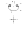
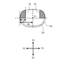
- FIG. 2 is a schematic cross-sectional view showing a state in which protrusions are provided at both left and right corners of the inner wall of the tube leading to the nozzle of the intraocular lens insertion device.
- Reference numeral 15 indicates the protrusion.
- the description of the reference numerals of the pipe and the protrusion in the specification will be omitted.
- the present inventor has diligently studied the above issues. As a result, as shown in FIG. 2, the posture of the optical part is shown by adopting the shape of the inner wall (that is, the protrusion) so that neither the optical part nor the support part can enter the left and right corners above the inner wall of the tube. It was found that it was folded into a valley fold shape while being corrected to the state of 1 (a).
- the first aspect of the present invention is An intraocular lens insertion device that advances an intraocular lens and ejects it from a nozzle while folding an intraocular lens having an optical portion having an optical function and a support portion extending from the optical portion.
- protrusions are provided at both left and right corners above the inner wall of the tube.
- This is an intraocular lens insertion device that prevents the optical portion and the support portion from entering both the left and right corners when the intraocular lens is folded while advancing due to the protrusion.
- the second aspect of the present invention is the aspect described in the first aspect.
- the bulge forms a space between the left and right corners that is wide enough to accommodate the folded support.
- the third aspect of the present invention is the aspect described in the first or second aspect.
- the bulge bulges inward horizontally and also bulges downward.
- a fourth aspect of the present invention is the aspect according to any one of the first to third aspects.
- a fifth aspect of the present invention is the aspect described in the fourth aspect.
- the minimum value of the inclination angle in the portion where the protrusion exists is in the range of 0 to 15 degrees.
- the sixth aspect of the present invention is the aspect described in the fourth or fifth aspect.
- the protrusion has a shape that changes the concave shape of both left and right corners in the cross-sectional shape of the inner wall into a convex shape.
- a seventh aspect of the present invention is the aspect according to any one of the first to sixth aspects. It has a tacking pin that bends the front support portion in contact with the front support portion that is one of the support portions and is arranged in the front.
- the tacking pin stands upward, and the surface in contact with the front support portion is a slope that becomes an uphill toward the front.
- the eighth aspect of the present invention is the aspect according to any one of the first to seventh aspects. It is a preload type with the intraocular lens mounted in advance.
- a ninth aspect of the present invention is A method for designing an intraocular lens insertion device in which an intraocular lens including an optical portion having an optical function and a support portion extending from the optical portion is folded and advanced in a tube to be discharged from a nozzle. It has a design change step of providing protrusions at both left and right corners above the inner wall of the tube in a cross-sectional view perpendicular to the traveling direction of the intraocular lens. It is a method of designing an intraocular lens insertion device that prevents the optical portion and the support portion from entering both the left and right corners when the intraocular lens is folded while advancing due to the protrusion.
- the aspect relating to the design method of the intraocular lens insertion device may have the characteristics of each of the above aspects.
- a protrusion may be provided at a position where the rate of change in the curvature of the cross-sectional shape of the inner wall is the largest.
- the inner wall has a bulge when the inclination angle ⁇ is preferably in the range of 0 to 15 degrees, more preferably 10 to 15 degrees.
- the width w in the Y1-Y2 direction of a protrusion (for example, a stepped protrusion) provided at the left corner is an inner wall in the left direction from a predetermined position of a perpendicular line formed by the left and right midpoints (for example, the upper, lower, left, and right midpoints O). 10 to 60% of the width W up to is preferable.
- the width of the protrusion provided in the left corner in the Y1-Y2 direction is 0.5 to 2.5 mm.
- a similar preferred example is used for the protrusion provided in the right corner.
- the height h of the protrusion (for example, the stepped protrusion) provided in the left corner in the Z1-Z2 direction is the upper inner wall and the lower inner wall in the vertical line passing through the upper, lower, left, and right middle points O. It is preferably 30 to 80% of the height H between and. As for the actual size, the height of the protrusion provided in the left corner in the Z1-Z2 direction is 0.5 to 1.5 mm. A similar preferred example is used for the protrusion provided in the right corner.
- a protrusion exists at least between the front end of the optical portion and the front end of the front support portion, and the protrusion is elongated in the front-rear direction so as to include both front ends. It is preferably formed.
- a bulge may be provided on the lid of the insertion cylinder body, and as a result, bulges may be formed at both left and right corners in the pipe when the lid is closed.
- the lower end of the bulge may be displaced downward as it moves forward.
- the lower end of the protrusion is displaced downward toward the front, at least in the connection portion with the rear support portion with respect to the optical portion.
- the length of the protrusion in the X1-X2 direction is not limited as long as it is long enough to normally complete the tacking of the front support portion with respect to the optical portion when the intraocular lens is advanced.
- the length of the protrusion provided in the left corner in the X1-X2 direction is 5 to 15 mm.
- a similar preferred example is used for the protrusion provided in the right corner.
- FIG. 1 is a schematic cross-sectional view of the inner wall of a tube leading to a nozzle of an intraocular lens insertion device.
- FIG. 2 is a schematic cross-sectional view showing how protrusions are provided at both left and right corners of the inner wall of the tube leading to the nozzle of the intraocular lens insertion device.
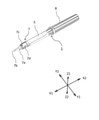
- FIG. 3 is a perspective view showing a configuration example of the appearance of the intraocular lens insertion device.
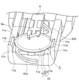
- FIG. 4 is a perspective view showing the structure and arrangement of the tip portion of the insertion instrument main body.
- FIG. 5 is a perspective view of the case of the intraocular lens insertion device.
- FIG. 6 is a perspective view showing a state in which the intraocular lens insertion device is attached to the case.
- FIG. 1 is a schematic cross-sectional view of the inner wall of a tube leading to a nozzle of an intraocular lens insertion device.
- FIG. 2 is a schematic cross-sectional view showing how protrusions are provided
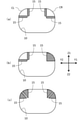
- FIG. 7 is a schematic cross-sectional view showing a modified example of the protrusion.
- FIG. 8A is a schematic cross-sectional view (No. 1) illustrating a method for more specifically specifying the positional relationship of the protrusions.
- FIG. 8B is a schematic cross-sectional view (No. 2) illustrating a method for more specifically specifying the positional relationship of the protrusions.
- FIG. 8C is a schematic cross-sectional view (No. 3) illustrating a method for more specifically specifying the positional relationship of the protrusions.
- FIG. 9 is a perspective view of another intraocular lens insertion device.
- FIG. 9 is a perspective view of another intraocular lens insertion device.
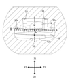
- FIG. 10 is a cross-sectional view of another intraocular lens insertion device, the center view is an XY cross-sectional view passing through the upper and lower center points of the intraocular lens insertion device, and the right side view is a center view. It is a cross-sectional view of XZ passing through line AA of No. 1, and the left side view (a)-(f) is a cross-sectional view of YZ.
- FIG. 11 is a schematic cross-sectional view of the XX plane showing the positional relationship between the front support portion and the tacking pin when the intraocular lens is advanced.
- one of the X-axis directions is the X1 direction, the other is the X2 direction, and one of the Y-axis directions is used.
- the Y1 direction, the other is the Y2 direction, one of the Z-axis directions is the Z1 direction, and the other is the Z2 direction.
- the X1 direction is the front end side (front, lens traveling direction)
- the X2 direction is the rear end side (rear)
- the Y1 direction is the right side (right side)
- the Y2 direction is the left side (left side)
- the Z1 direction is the upper side (upper side).
- the thickness direction and the optical axis direction when the intraocular lens is placed) and the Z2 direction are defined as the lower side (lower side).
- the X1 direction and the X2 direction correspond to the length direction of the intraocular lens insertion device 1
- the Y1 direction and the Y2 direction correspond to the width direction of the intraocular lens insertion device
- the Z1 direction and the Z2 direction correspond to the width direction of the intraocular lens insertion device. It corresponds to the height direction of the intraocular lens insertion device 1.
- a preload type intraocular lens insertion device equipped with an intraocular lens in advance is exemplified, but the present invention is not limited thereto.
- FIG. 3 is a perspective view showing a configuration example of the appearance of the intraocular lens insertion device according to the embodiment of the present invention.
- FIG. 4 is a perspective view showing the structure and arrangement of the tip portion of the insertion instrument main body according to the embodiment of the present invention.
- the intraocular lens insertion device 1 is used when inserting an intraocular lens into the eye.
- a one-piece type intraocular lens 4 (see FIG. 4) made of a soft material such as silicone elastomer or soft acrylic, which has circular effective optics that fulfills an optical function. It handles an intraocular lens 4 having an optical portion 41 including a portion 41a and a peripheral portion 41b thereof, and two support portions 42a and 42b curved outward from two locations on the outer peripheral portion of the optical portion 41. do.
- Reference numeral 42a indicates a front support portion arranged in the front when the lens is installed in the lens mounting portion 11, and reference numeral 42b indicates a rear support portion arranged in the rear.
- optical portion 41 of the intraocular lens 4 and the proximal end side of the support portions 42a and 42b connected to the optical portion 41 are made of a soft material. This configuration facilitates folding of the intraocular lens 4.
- the terminal sides of the support portions 42a and 42b may also be made of a soft material or a hard material (eg, polyethylene, PMMA, etc.).
- the effective optical portion 41a in the optical portion 41 has a shape that exerts an optical function
- the peripheral portion 41b is formed in an annular shape around the effective optical portion 41a, and the annular portion has a flat plate shape.
- the optical unit 41 may be configured from only the effective optical unit 41a.
- the peripheral edge portion 41b may be continuously formed with the effective optical portion 41a, that is, the peripheral edge portion 41b and the effective optical portion 41a may be smoothly connected to form a continuous surface.
- the intraocular lens insertion device 1 is arranged inside the insertion device main body 5, the slider 6, the insertion tube 7, the rotating member 8, the plunger 9, and the rod 10 (the intraocular lens insertion device 1 in FIG. 3). (Hidden), and the configuration is equipped with. Each of these components is preferably composed of a molded resin product.
- the insertion instrument main body 5 and the insertion cylinder 7 each have a hollow structure, and are connected to each other to form a hollow body.
- the present invention is characterized in the shape of the inner wall of the hollow tube.
- the slider 6 is attached to the insertion instrument main body 5.
- the intraocular lens 4 is advanced and bent into a valley fold shape (bent downward) along the narrowing inner diameter of the insertion cylinder main body 7a.
- the bent intraocular lens 4 is advanced by the plunger 9 and thus by the rod 10, and is discharged from the nozzle portion 7b.
- the insertion cylinder 7 is arranged so as to communicate with the tip of the insertion instrument main body 5.
- the insertion tube 7 and the tip of the insertion instrument main body 5 may be integrally molded, or may be molded separately and the insertion tube 7 may be attached to the tip.
- the insertion tube 7 has a hollow insertion tube main body 7a and a thin tubular nozzle portion 7b.
- the lens installation portion 11 of the insertion instrument main body 5 is housed and arranged in the insertion cylinder main body 7a of the insertion cylinder 7 together with the intraocular lens 4 installed there.
- An injection hole 7c is formed on the upper surface of the insertion cylinder main body 7a.
- the injection hole 7c is for injecting a viscoelastic substance (for example, sodium hyaluronate).
- the viscoelastic substance injected from the injection hole 7c is supplied to the intraocular lens 4 installed in the lens mounting portion 11.
- the rotating member 8 is rotatably connected to the rear end portion of the insertion device main body 5.
- the plunger 9 is arranged coaxially with the insertion device main body 5. A part of the plunger 9 is arranged inside the insertion instrument main body 5 via the rotating member 8, and the other part of the plunger 9 is arranged so as to project rearward from the rotating member 8.
- the rod 10 is arranged inside a hollow body including the insertion instrument main body 5 and the insertion cylinder 7.
- the rod 10 is connected to the plunger 9 and plays a role of advancing the intraocular lens 4.
- the lens installation portion 11 includes a bottom surface portion 11a, a lens receiving portion 11b, and a lens guide portion 11c.
- the lens receiving portion 11b receives and supports the intraocular lens 4 from below.
- the intraocular lens 4 is installed in the lens mounting portion 11 with the front support portion 42a arranged in the front (X1 direction) as its name suggests and the other rear support portion 42b in the rear (X2 direction) as its name suggests. ..
- the intraocular lens insertion device 1 is a preload type in which the intraocular lens 4 is previously installed in the lens installation portion 11 of the insertion device main body 5. Therefore, the intraocular lens 4 is one of the components of the intraocular lens insertion device 1. However, in carrying out the present invention, it does not necessarily have to be a preload type.
- ⁇ Case configuration> As the structure of the case, for example, the structure of Japanese Patent No. 5254669 by the applicant may be adopted. Regarding the structure of the case, the contents not described below shall adopt the structure of the specification of the patent No. 5254669, and the description of the specification of the patent No. 5254669 shall be fully described in the present specification.
- Japanese Patent No. 5254669 describes that the intraocular lens 4 is installed in the lens mounting portion in a state where the front support portion is bent by the protruding portion 80, but in the present embodiment, WO2018 / 003854 As described in the publication, the portion where the intraocular lens 4 in the state before bending is placed is treated as the lens mounting portion 11.
- FIG. 5 is a perspective view of the case of the intraocular lens insertion device according to the embodiment of the present invention.
- FIG. 6 is a perspective view showing a state in which the intraocular lens insertion device according to the embodiment of the present invention is attached to the case.
- the intraocular lens insertion device 1 can be detachably attached to, for example, a case 62 integrally molded of a synthetic resin material.
- the case 62 has a U-shaped wall portion 76 on the bottom plate portion 75 so as to surround the intraocular lens insertion device 1.
- the tacking pin 20 is erected at a predetermined position of the bottom plate portion 75.
- the tacking pin 20 is a protrusion of the intraocular lens insertion device 1 by attaching the intraocular lens insertion device 1 to the case 62. It is configured so that it can be inserted into the insertion hole 73. As a result, the tacking pin 20 of the case 62 can be arranged in the central region of the moving space of the tip member 71 in the intraocular lens insertion device 1.
- the slider 6 advances the intraocular lens 4 mounted on the lens mounting portion 11 toward the discharge hole of the nozzle portion 7b.
- this advance may be performed by the plunger 9 (directly, the rod 10 connected to the plunger 9). Therefore, the rod 10 connected to the slider 6 or the plunger 9 is also referred to as a forward member.
- the intraocular lens 4 abuts the front support portion 42a on the tacking pin 20, and the tip of the front support portion 42a is folded back in the direction opposite to the lens traveling direction (front, X1 direction) (X2 direction). It is folded into an almost U shape.
- the intraocular lens insertion device 1 is detached from the case 62 in this state, and the intraocular lens 4 is pushed forward (in the X1 direction) by the plunger 9 while the front support portion 42a is bent. Yuki, the intraocular lens 4 can be discharged into the eye from the nozzle portion 7b.
- the main feature of this embodiment is that protrusions are provided at the left and right corners of the inner wall of the tube through which the intraocular lens passes toward the nozzle.
- the configuration of a known intraocular lens insertion device may be adopted.
- the structure of WO2018 / 003854 by the applicant may be adopted.
- the contents not described below shall adopt the configuration of a known intraocular lens insertion device (for example, the configuration of WO2018 / 003854), and all the descriptions of WO2018 / 003854 are described in the present specification. It shall be.
- FIGS. 3 and 4 of the present application are similar in configuration to FIGS. 1 and 6 of WO2018 / 003854 except for the intraocular lens 4. Therefore, among the codes shown in FIG. 4 of the present application, the reference numerals not described in the present specification are as described in WO2018 / 003854.
- the configuration of the characteristic portion of the intraocular lens insertion device is as follows. "An intraocular lens insertion device that advances an intraocular lens and ejects it from a nozzle while folding an intraocular lens having an optical portion having an optical function and a support portion extending from the optical portion. In the cross-sectional view perpendicular to the traveling direction of the intraocular lens, protrusions are provided at both left and right corners above the inner wall of the tube. An intraocular lens insertion device that prevents the optical portion and the support portion from entering both the left and right corners when the intraocular lens is folded while advancing due to the protrusion. "An intraocular lens insertion device that advances an intraocular lens and ejects it from a nozzle while folding an intraocular lens having an optical portion having an optical function and a support portion extending from the optical portion. In the cross-sectional view perpendicular to the traveling direction of the intraocular lens, protrusions are provided at both left and right corners above the inner wall of
- the shape of the inner wall of the tube inside the intraocular lens insertion device is a major feature.
- the tube is formed by an insertion instrument main body and an insertion tube forming a hollow structure.
- the "inner wall” forms the innermost contour of the tube, which is the passage through which the intraocular lens passes, in a cross-sectional view perpendicular to the traveling direction of the intraocular lens (cross-sectional view in the YZ plane). It is the part to do.
- Patent Documents 1 and 2 although protrusions are formed downward from the top plate portion, the upper left and right corners of the inner wall of the pipe remain concave. Specifically, the left corner of the inner wall on the left side of reference numeral 42 in FIG. 4 of Patent Document 1 and the right corner portion of the inner wall on the right side of reference numeral 44 remain concave (convex toward the outside of the tube). The same applies to the left corner of the inner wall on the left side of reference numeral 46 in FIG. 5 of Patent Document 2 and the right corner portion of the inner wall on the right side of reference numeral 44.
- protrusions are provided at both left and right corners above the inner wall of the tube in a cross-sectional view perpendicular to the traveling direction of the intraocular lens (cross-sectional view in the YY plane).
- the description of the inner wall of the pipe is premised on a cross-sectional view (cross-sectional view in the YY plane) unless otherwise specified.
- this configuration is based on the new finding that the penetration of the optical portion or the support portion into the left and right corners affects the folding accuracy.
- the cross-sectional view shape before forming the bulge of the present embodiment is an elliptical shape having Y1-Y2 as a major axis and Z1-Z2 as a minor axis.
- FIG. 7 is a schematic cross-sectional view showing a modified example of the protrusion.
- the left and right corners in the present embodiment refer to the vicinity of the left and right corners (near CR and CL in FIG. 2) in the virtual cross-sectional contour line in which the curvature is continuously changed between both ends of the protrusion. If the left and right corners are not covered with protrusions as shown in FIG. 7 (a) but are isolated, the vicinity of the left and right corners in the actual cross-sectional contour line (near CR and CL in FIG. 2). Point to.
- the bulge is the part where the curvature changes sharply at the base of the bulge.
- a state in which the curvature of the base portion of the bulge is 10 times or more larger than the curvature in front of the base of the bulge (that is, the inner diameter shape of the pipe in the vicinity of the bulge) may be regarded as the bulge.
- a portion where the curvature changes discontinuously from the curvature in front of the root of the bulge may be regarded as the root of the bulge.
- the area where the optical part and the support part can move can be reduced.
- the posture of the optical portion is corrected to the state shown in FIG. 1A, and the lens is folded into a valley fold shape, and both the front support portion and the rear support portion are sandwiched between the optical portions, so that the intraocular lens can be folded accurately.
- protrusion there is no limit to the form of protrusion (number, material, shape, etc.). It is sufficient that neither the optical portion nor the support portion can enter the left and right corners when the intraocular lens is folded while advancing.
- the number of protrusions as shown in Fig. 2, one can be used for each of the left and right corners (two in total), one for each of the left and right corners, one protruding downward, and the other inward. It may be projected horizontally (Fig. 7 (a)). The number may be different at the left and right corners (FIG. 7 (b)). For example, it does not prevent the provision of a plurality of protrusions at intervals such that the optical portion and the support portion are not sandwiched (FIG. 7 (c)).
- the material of the protrusion if it is the same as the material of the insertion instrument main body and the hollow body which is the insertion cylinder, it is preferable that it can be integrally formed by injection molding, but it may be a different material.
- the bulge forms a space (for example, reference numeral S in FIG. 2) between the left and right corners so as to accommodate the folded support portion. ..
- the front support portion and the rear support portion extend from the optical portion in the intraocular lens.
- the rear support portion is bent and arranged on the optical portion, and then the intraocular lens is advanced.
- bending and arranging the support portion on the optical portion is referred to as "tacking".
- the intraocular lens When the rear support portion is tacked in advance, if a space S having a width capable of accommodating the folded support portion is formed between the left and right corners, the intraocular lens will move forward when the intraocular lens is advanced.
- the rear support portion fits in this space S. If this space S is not present, the rear support portion in the tacked state comes into contact with the left and right protrusions. If the intraocular lens moves forward while in contact, tacking may be released due to friction caused by the left and right protrusions. With this space S, the possibility that such a situation occurs can be reduced.
- the tip portion of the slider is provided in the space S described in the previous paragraph. May be accommodated.
- the bulge protrudes inward in the horizontal direction and also protrudes downward at both the left and right corners as shown in FIG. With this configuration, neither the optical portion nor the support portion can reliably enter the left and right corners.
- This stepped protrusion may have a rounded stepped portion as long as the posture of the optical portion is corrected.
- FIGS. 8A to 8C are schematic cross-sectional views (Nos. 1 to 3) illustrating a method for more specifically specifying the positional relationship of the protrusions.
- the inner wall has a bulge within the range of the inclination angle ⁇ from the horizon of 0 to 20 degrees (preferably 0 to 15 degrees, more preferably 10 to 15 degrees).
- any or the entire inner wall in the range of the inclination angle ⁇ of 0 to 20 degrees may be set as the upper left and right corners.
- the present invention does not prevent the presence of a bulge on the inner wall within the range where ⁇ is less than 0 degrees and exceeds 20 degrees.
- the minimum value of the inclination angle ⁇ in the portion where the protrusion exists is preferably in the range of 0 to 15 degrees. That is, it is preferable that the start position of the bulge is within the range of the inclination angle ⁇ of 0 to 15 degrees, and the bulge is continuously or discontinuously provided with respect to the inner wall as the ⁇ increases from the start position.
- the protrusion preferably has a shape that changes the concave shape (convex outward) of the left and right corners of the cross-sectional shape of the inner wall to a convex shape (convex inward). Further, a protrusion may be provided at a position where the rate of change in the curvature of the cross-sectional shape of the inner wall is the largest.
- the width w in the Y1-Y2 direction of a protrusion (for example, a stepped protrusion) provided at the left corner is an inner wall in the left direction from a predetermined position of a perpendicular line formed by the left and right midpoints (for example, the upper, lower, left, and right midpoints O). 10 to 60% of the width W up to is preferable.
- the width of the protrusion provided in the left corner in the Y1-Y2 direction is 0.5 to 2.5 mm.
- a similar preferred example is used for the protrusion provided in the right corner.
- the height h of the protrusion (for example, the stepped protrusion) provided in the left corner in the Z1-Z2 direction is the upper inner wall and the lower inner wall in the vertical line passing through the upper, lower, left, and right middle points O. It is preferably 30 to 80% of the height H between and. As for the actual size, the height of the protrusion provided in the left corner in the Z1-Z2 direction is 0.5 to 1.5 mm. A similar preferred example is used for the protrusion provided in the right corner.
- FIG. 9 is a perspective view of another intraocular lens insertion device.
- FIG. 10 is a cross-sectional view of another intraocular lens insertion device, the center view is an XY cross-sectional view passing through the upper and lower center points of the intraocular lens insertion device, and the right side view is a center view. It is a cross-sectional view of XZ passing through line AA of No. 1, and the left side view (a)-(f) is a cross-sectional view of YZ.
- FIGS. 3 to 6 described so far show an intraocular lens insertion device 1 in which the slider 6 is used, while FIGS. 9 and 10 do not use the slider 6.
- a lid 7d is provided above the lens mounting portion 11.
- the lid 7d can be opened and closed.
- FIG. 10 shows an example in which a protrusion 15 is provided on the lid 7d, and as a result, the protrusion 15 is formed at both left and right corners in the pipe when the lid 7d is closed.
- the arrangement of the bulge (for example, the stepped bulge) in the X1-X2 (front-back) direction is not limited as long as the tacking of the front support portion with respect to the optical portion is normally completed when the intraocular lens is advanced. From the viewpoint of accurately folding the intraocular lens 4, it is preferable to provide a protrusion at a position that contributes to folding.
- a protrusion at a position where the optical portion 41 exists after the start of folding of the intraocular lens 4, and in FIG. 10, it is preferable to provide a protrusion at least between (e) and (f).
- a protrusion between (e) and (f) is at least between the front end of the optical portion 41 and the front end of the front support portion 42a. It is preferable that the bulge is formed long in the front-rear direction so as to include both front ends.
- a long protrusion is formed between the portion where the optical portion 41 does not exist (FIG. 10 (a)) at the start of folding of the intraocular lens 4 and the front end of the front support portion 42a. May be good.
- the member provided with the protrusion is not limited, but as shown in FIG. 10, a protrusion may be provided on the lid 7d, and as a result, protrusions may be provided at both left and right corners in the pipe when the lid 7d is closed.
- protrusions may be provided at both left and right corners of the inner wall of the tube of the insertion tube main body 7a.
- the lower end of the bulge may be displaced downward toward the front.
- the intraocular lens 4 is mounted on the lens mounting portion 11, at least in the connection portion with the rear support portion 42b with respect to the optical portion 41 (for example, the portion extending from FIGS. 10 (a) to 10 (b)), the front is forward. It is preferable to displace the lower end of the bulge downward as it goes toward it, as it helps to properly tack the rear support portion 42b.
- the length of the protrusion in the X1-X2 direction is not limited as long as it is long enough to normally complete the tacking of the front support portion with respect to the optical portion when the intraocular lens is advanced.
- the length of the protrusion provided in the left corner in the X1-X2 direction is 5 to 15 mm.
- a similar preferred example is used for the protrusion provided in the right corner.
- the protrusion 20 is inserted into the protrusion insertion hole 73 of the intraocular lens insertion device 1 by mounting the intraocular lens insertion device 1 on the case 62. It is configured to get.
- the protrusion 20 of the case 62 can be arranged in the central region of the moving space of the tip member 71.
- the intraocular lens 4 mounted on the lens mounting portion 11 is advanced toward the ejection hole of the nozzle portion 7b by the slider 6.
- the intraocular lens 4 abuts the front support portion 42a on the protrusion 20 and the tip of the front support portion 42a is folded back in the direction opposite to the lens traveling direction (front, X1 direction) (X2 direction). It is folded into an almost U shape.
- the protrusion 20 is also referred to as a tacking pin 20.
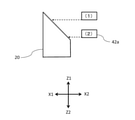
- FIG. 11 is a schematic cross-sectional view of the XX plane showing the positional relationship between the front support portion and the tacking pin when the intraocular lens is advanced.
- the tacking pin 20 stands up upward, and the surface in contact with the front support portion 42a is a slope that becomes an uphill toward the front. Is preferable.
- the tacking pin 20 and the front support portion 42a are arranged at an earlier timing than the conventional front support portion shown in FIG. 11 (1). (2) in FIG. 11 is in contact with.
- the front support portion 42a enters between the outer surface opposite to the inner surface of the optical portion 41 and the inner wall of the intraocular lens insertion device 1 can be reduced.
- the support portions 42a and 42b of the intraocular lens 4 are made of the viscoelastic material due to the difference in specific gravity with the viscoelastic material passing through the tube together with the intraocular lens 4. It tends to rise from the inside. Even in this case, if the configuration of the present embodiment is adopted, the optical unit 41 and the support units 42a and 42b are naturally arranged downward.
- the present inventor paid attention to the movement when the front support portion abuts on the protruding portion described in Japanese Patent No. 5254669.
- the protruding portion described in Patent No. 5254669 when the entire intraocular lens advances forward, the anterior support portion continues to bend backward and the tip of the anterior support portion inserts the intraocular lens. It is clear that the timing of moving near the inner wall of the instrument and the timing of advancing the peripheral edge of the optical part in the folded intraocular lens are very close or the tip of the anterior support tends to move to the inner wall earlier. It became.
- the present inventor displaces the tip of the front support portion 42a, which bends backward, more quickly than before when the entire intraocular lens 4 advances, and the front support portion 42a Created the technical idea of accelerating the timing of movement to the vicinity of the inner wall. If the timing is early, the optical unit 41 is not yet near when the front support portion 42a moves near the inner wall. When the optical unit 41 approaches, the front support portion 42a bends, and the front support portion 42a has already moved away from the vicinity of the inner wall. As a result, the possibility that the front support portion 42a is sandwiched between the optical portion 41 and the lower inner wall can be reduced.
- an intraocular lens insertion device using a slider is illustrated, but the present invention can be applied even when the intraocular lens is advanced only by the rod 10 (plunger 9) without using the slider.
- the present invention is applicable with or without a slider and is highly versatile.
- the present invention also has technical significance as a method for designing an intraocular lens insertion device.
- the contents are as follows.
- a method of designing an intraocular lens insertion device that advances an intraocular lens and ejects it from a nozzle while folding an intraocular lens having an optical portion having an optical function and a support portion extending from the optical portion. It has a design change step of providing protrusions at both left and right corners above the inner wall of the tube in a cross-sectional view perpendicular to the traveling direction of the intraocular lens.
- a method for designing an intraocular lens insertion device that prevents the optical portion and the support portion from entering both the left and right corners when the intraocular lens is folded while advancing due to the protrusion.
- the feature of the design method of the intraocular lens insertion device is that the shape of the inner wall of the tube through which the intraocular lens passes is redesigned with respect to the basic design before the design change.
- the inner wall of the tube is designed as shown in FIG. 2, as opposed to the basic design of the inner wall of the tube before the design change (for example, FIG. It is not necessary to change the cross-sectional shape of the inner wall of the pipe, except for providing protrusions at the upper left and right corners.
- the intraocular lens insertion device is the intraocular lens insertion device in which the difference between the shape of the inner wall of the tube before the design change and the shape of the inner wall of the tube after the design change is only the protrusion described above. It can be considered that the design method of the lens insertion device is used.
- the technical scope of the present invention is not limited to the above-mentioned embodiment, but also includes a form in which various changes and improvements are made to the extent that a specific effect obtained by the constituent requirements of the invention and the combination thereof can be derived.
- Intraocular lens insertion device 5 ... Insertion device body 6 ... Slider 7 ... Insert tube 7a ... Insert tube body 7b ... Nozzle part 7c ... Injection hole 7d ... Lid 8 ... Rotating member 9 ... Plunger 10 ... Rod 11 ... Lens installation part 11a ... Bottom portion 11b ... Lens receiving portion 11c ... Lens guide portion 15 ... Protrusion 15a ... (Protrusion) lower end 30 ... Tube inner wall 73 ... Projection insertion hole 62 ... Case 20 ... Protrusion (tacking pin) 75 ... Bottom plate 76 ... U-shaped wall 4 ... Intraocular lens 41 ... Optical part 41a ... Effective optical part 41b ... Peripheral part 42a ... Front support part 42b ... Rear support part
Landscapes
- Health & Medical Sciences (AREA)
- Ophthalmology & Optometry (AREA)
- Cardiology (AREA)
- Oral & Maxillofacial Surgery (AREA)
- Transplantation (AREA)
- Engineering & Computer Science (AREA)
- Biomedical Technology (AREA)
- Heart & Thoracic Surgery (AREA)
- Vascular Medicine (AREA)
- Life Sciences & Earth Sciences (AREA)
- Animal Behavior & Ethology (AREA)
- General Health & Medical Sciences (AREA)
- Public Health (AREA)
- Veterinary Medicine (AREA)
- Prostheses (AREA)
Abstract
Description
符号10は管の内壁を示す。符号41は眼内レンズの光学部を指す。
図1(a)は、光学部が正常に谷折り形状に折り畳まれる様子を示す図であり、図1(b)~(d)は、光学部が左右両隅部に侵入することにより、光学部が異常な状態で折り畳まれる様子を示す図である。
図1(b)は、光学部と管の下方内壁との間に隙間Gが形成される様子を示す図である。図1(c)は、光学部が山折り形状に折り畳まれる様子を示す図である。図1(d)は、光学部が谷折り形状と山折り形状とが不均一となった状態で折り畳まれる様子を示す図である。
本発明の第1の態様は、
光学機能を有する光学部と、前記光学部から延在する支持部と、を備える眼内レンズを折り畳みながら管内を前進させてノズルから放出する、眼内レンズ挿入器具であって、
前記眼内レンズの進行方向に垂直な断面視において前記管の内壁の上方の左右両隅部に出っ張りが設けられ、
前記出っ張りにより、前記眼内レンズが前進しながら折り畳まれる際に前記光学部も前記支持部も前記左右両隅部に進入できないようにした、眼内レンズ挿入器具である。
前記出っ張りにより、前記左右両隅部の間に、折り畳まれた状態の前記支持部を収容可能な幅の空間が形成される。
前記出っ張りは、内向き水平方向に出っ張り且つ下方にも出っ張る。
前記管の内壁の断面形状の上下左右の中点を通過する水平線からの傾斜角度が0~20度の範囲内のいずれかにおいて前記内壁に出っ張りが存在する。
前記出っ張りが存在する部分における前記傾斜角度の最小値は0~15度の範囲内にある。
前記出っ張りは、前記内壁の断面形状における左右両隅部の凹形状を凸形状に変化させる形状を有する。
前記支持部のうちの一つであって前方に配置された前方支持部に接触させて前記前方支持部を折り曲げるタッキングピンを有し、
前記タッキングピンは上方に向けて起立し、且つ、前記前方支持部と接触する面は前方に向かって上り坂となる斜面である。
前記眼内レンズが予め搭載されたプリロード型である。
光学機能を有する光学部と、前記光学部から延在する支持部と、を備える眼内レンズを折り畳みながら管内を前進させてノズルから放出する、眼内レンズ挿入器具の設計方法であって、
前記眼内レンズの進行方向に垂直な断面視において前記管の内壁の上方の左右両隅部に出っ張りを設ける設計変更工程を有し、
前記出っ張りにより、前記眼内レンズが前進しながら折り畳まれる際に前記光学部も前記支持部も前記左右両隅部に進入できないようにする、眼内レンズ挿入器具の設計方法である。
図3は、本発明の実施形態に係る眼内レンズ挿入器具の外観の構成例を示す斜視図である。
図4は、本発明の実施形態に係る挿入器具本体の先端部分の構造及び配置を示す斜視図である。
ケースの構成としては、例えば本出願人による特許第5254669号明細書の構成を採用して差し支えない。ケースの構成に関し、以下に記載が無い内容は、特許第5254669号明細書の構成を採用するものとし、特許第5254669号明細書の記載は本明細書に全て記載されているものとする。
図6は、本発明の実施形態に係る眼内レンズ挿入器具をケースに装着した様子を示す斜視図である。
以下、本実施形態に係る眼内レンズ挿入器具の特徴部分に焦点を当てる。
「光学機能を有する光学部と、前記光学部から延在する支持部と、を備える眼内レンズを折り畳みながら管内を前進させてノズルから放出する、眼内レンズ挿入器具であって、
前記眼内レンズの進行方向に垂直な断面視において前記管の内壁の上方の左右両隅部に出っ張りが設けられ、
前記出っ張りにより、前記眼内レンズが前進しながら折り畳まれる際に前記光学部も前記支持部も前記左右両隅部に進入できないようにした、眼内レンズ挿入器具。」
図10は、別の眼内レンズ挿入器具の断面図であり、中央の図は、眼内レンズ挿入器具の上下中央点を通過するX-Y断面図であり、右側の図は、中央の図のA-A線を通過するX-Z断面図であり、左側の図(a)~(f)は、Y-Z断面図である。
本発明は、眼内レンズ挿入器具の設計方法としても技術的意義がある。その内容は以下の通りである。
「光学機能を有する光学部と、前記光学部から延在する支持部と、を備える眼内レンズを折り畳みながら管内を前進させてノズルから放出する、眼内レンズ挿入器具の設計方法であって、
前記眼内レンズの進行方向に垂直な断面視において前記管の内壁の上方の左右両隅部に出っ張りを設ける設計変更工程を有し、
前記出っ張りにより、前記眼内レンズが前進しながら折り畳まれる際に前記光学部も前記支持部も前記左右両隅部に進入できないようにする、眼内レンズ挿入器具の設計方法。
」
5…挿入器具本体
6…スライダ
7…挿入筒
7a…挿入筒本体
7b…ノズル部
7c…注入孔
7d…蓋
8…回転部材
9…プランジャ
10…ロッド
11…レンズ設置部
11a…底面部
11b…レンズ受け部
11c…レンズガイド部
15…出っ張り
15a…(出っ張りの)下端
30…管の内壁
73…突起挿入孔
62…ケース
20…突起部(タッキングピン)
75…底板部
76…U字状の壁部
4…眼内レンズ
41…光学部
41a…有効光学部
41b…周縁部
42a…前方支持部
42b…後方支持部
Claims (9)
- 光学機能を有する光学部と、前記光学部から延在する支持部と、を備える眼内レンズを折り畳みながら管内を前進させてノズルから放出する、眼内レンズ挿入器具であって、
前記眼内レンズの進行方向に垂直な断面視において前記管の内壁の上方の左右両隅部に出っ張りが設けられ、
前記出っ張りにより、前記眼内レンズが前進しながら折り畳まれる際に前記光学部も前記支持部も前記左右両隅部に進入できないようにした、眼内レンズ挿入器具。 - 前記出っ張りにより、前記左右両隅部の間に、折り畳まれた状態の前記支持部を収容可能な幅の空間が形成される、請求項1に記載の眼内レンズ挿入器具。
- 前記出っ張りは、内向き水平方向に出っ張り且つ下方にも出っ張る、請求項1又は2に記載の眼内レンズ挿入器具。
- 前記管の内壁の断面形状の上下左右の中点を通過する水平線からの傾斜角度が0~20度の範囲内のいずれかにおいて前記内壁に出っ張りが存在する、請求項1~3のいずれか一つに記載の眼内レンズ挿入器具。
- 前記出っ張りが存在する部分における前記傾斜角度の最小値は0~15度の範囲内にある、請求項4に記載の眼内レンズ挿入器具。
- 前記出っ張りは、前記内壁の断面形状における左右両隅部の凹形状を凸形状に変化させる形状を有する、請求項4又は5に記載の眼内レンズ挿入器具。
- 前記支持部のうちの一つであって前方に配置された前方支持部に接触させて前記前方支持部を折り曲げるタッキングピンを有し、
前記タッキングピンは上方に向けて起立し、且つ、前記前方支持部と接触する面は前方に向かって上り坂となる斜面である、請求項1~6のいずれか一つに記載の眼内レンズ挿入器具。 - 前記眼内レンズが予め搭載されたプリロード型である、請求項1~7のいずれか一つに記載の眼内レンズ挿入器具。
- 光学機能を有する光学部と、前記光学部から延在する支持部と、を備える眼内レンズを折り畳みながら管内を前進させてノズルから放出する、眼内レンズ挿入器具の設計方法であって、
前記眼内レンズの進行方向に垂直な断面視において前記管の内壁の上方の左右両隅部に出っ張りを設ける設計変更工程を有し、
前記出っ張りにより、前記眼内レンズが前進しながら折り畳まれる際に前記光学部も前記支持部も前記左右両隅部に進入できないようにする、眼内レンズ挿入器具の設計方法。
Priority Applications (3)
| Application Number | Priority Date | Filing Date | Title |
|---|---|---|---|
| EP21866578.4A EP4212128B1 (en) | 2020-09-09 | 2021-08-30 | An intraocular lens injector and a method for designing an intraocular lens injector |
| CN202180043769.XA CN115867228A (zh) | 2020-09-09 | 2021-08-30 | 眼内透镜插入器具及其设计方法 |
| US18/044,235 US20230372083A1 (en) | 2020-09-09 | 2021-08-30 | Intraocular lens injector and its design method |
Applications Claiming Priority (2)
| Application Number | Priority Date | Filing Date | Title |
|---|---|---|---|
| JP2020151086A JP7430128B2 (ja) | 2020-09-09 | 2020-09-09 | 眼内レンズ挿入器具及びその設計方法 |
| JP2020-151086 | 2020-09-09 |
Publications (1)
| Publication Number | Publication Date |
|---|---|
| WO2022054619A1 true WO2022054619A1 (ja) | 2022-03-17 |
Family
ID=80631679
Family Applications (1)
| Application Number | Title | Priority Date | Filing Date |
|---|---|---|---|
| PCT/JP2021/031663 Ceased WO2022054619A1 (ja) | 2020-09-09 | 2021-08-30 | 眼内レンズ挿入器具及びその設計方法 |
Country Status (5)
| Country | Link |
|---|---|
| US (1) | US20230372083A1 (ja) |
| EP (1) | EP4212128B1 (ja) |
| JP (1) | JP7430128B2 (ja) |
| CN (1) | CN115867228A (ja) |
| WO (1) | WO2022054619A1 (ja) |
Cited By (1)
| Publication number | Priority date | Publication date | Assignee | Title |
|---|---|---|---|---|
| CN116269927A (zh) * | 2023-02-17 | 2023-06-23 | 天津世纪康泰生物医学工程有限公司 | 一种非对称式人工晶体植入器导入头 |
Families Citing this family (5)
| Publication number | Priority date | Publication date | Assignee | Title |
|---|---|---|---|---|
| EP2161005B1 (en) | 2007-05-30 | 2016-12-28 | Hoya Corporation | Intraocular lens inserting tool |
| CN109414345B (zh) | 2016-06-28 | 2023-04-07 | Hoya株式会社 | 眼内透镜插入器 |
| JP7162443B2 (ja) | 2018-05-16 | 2022-10-28 | Hoya株式会社 | 容器付き眼内リング挿入器 |
| JP7162445B2 (ja) | 2018-05-25 | 2022-10-28 | Hoya株式会社 | 眼内レンズ挿入器 |
| JP7327956B2 (ja) | 2019-03-13 | 2023-08-16 | Hoya株式会社 | 眼内レンズ挿入器具 |
Citations (8)
| Publication number | Priority date | Publication date | Assignee | Title |
|---|---|---|---|---|
| JP2006333980A (ja) * | 2005-05-31 | 2006-12-14 | Canon Star Kk | 眼内挿入用レンズの挿入器具 |
| WO2008149795A1 (ja) * | 2007-05-30 | 2008-12-11 | Hoya Corporation | 眼内レンズ挿入器具 |
| WO2011048631A1 (ja) * | 2009-10-22 | 2011-04-28 | 株式会社メニコン | 眼内レンズ挿入器具 |
| JP2011255029A (ja) * | 2010-06-10 | 2011-12-22 | Hoya Corp | 眼内レンズ挿入装置 |
| JP5254669B2 (ja) | 2008-06-05 | 2013-08-07 | Hoya株式会社 | 眼内レンズ挿入器具及びカートリッジ |
| JP2016049321A (ja) | 2014-09-01 | 2016-04-11 | 株式会社ニデック | 眼内レンズ挿入器具 |
| JP2016189925A (ja) | 2015-03-31 | 2016-11-10 | 株式会社ニデック | 眼内レンズ挿入器具 |
| WO2018003854A1 (ja) | 2016-06-28 | 2018-01-04 | Hoya株式会社 | 眼内レンズ挿入器 |
Family Cites Families (7)
| Publication number | Priority date | Publication date | Assignee | Title |
|---|---|---|---|---|
| ES2625005T3 (es) * | 2012-11-09 | 2017-07-18 | Bausch & Lomb Incorporated | Método para cargar una lente intraocular en un dispositivo inyector |
| JP5694489B2 (ja) * | 2013-11-25 | 2015-04-01 | 興和株式会社 | 眼内レンズ挿入器具 |
| JP6276619B2 (ja) * | 2014-03-19 | 2018-02-07 | Hoya株式会社 | 眼内レンズ挿入器および眼内レンズ挿入装置 |
| JP6646987B2 (ja) * | 2015-09-16 | 2020-02-14 | Hoya株式会社 | 眼内レンズ挿入器具 |
| US20200268507A1 (en) * | 2015-12-15 | 2020-08-27 | Santen Pharmaceutical Co., Ltd. | Lens holder and injector for intraocular lens |
| JP7095284B2 (ja) * | 2018-01-09 | 2022-07-05 | 株式会社ニデック | 眼内レンズ |
| JP7547719B2 (ja) * | 2019-02-28 | 2024-09-10 | 株式会社ニデック | 眼内レンズ挿入器具 |
-
2020
- 2020-09-09 JP JP2020151086A patent/JP7430128B2/ja active Active
-
2021
- 2021-08-30 US US18/044,235 patent/US20230372083A1/en active Pending
- 2021-08-30 EP EP21866578.4A patent/EP4212128B1/en active Active
- 2021-08-30 WO PCT/JP2021/031663 patent/WO2022054619A1/ja not_active Ceased
- 2021-08-30 CN CN202180043769.XA patent/CN115867228A/zh active Pending
Patent Citations (8)
| Publication number | Priority date | Publication date | Assignee | Title |
|---|---|---|---|---|
| JP2006333980A (ja) * | 2005-05-31 | 2006-12-14 | Canon Star Kk | 眼内挿入用レンズの挿入器具 |
| WO2008149795A1 (ja) * | 2007-05-30 | 2008-12-11 | Hoya Corporation | 眼内レンズ挿入器具 |
| JP5254669B2 (ja) | 2008-06-05 | 2013-08-07 | Hoya株式会社 | 眼内レンズ挿入器具及びカートリッジ |
| WO2011048631A1 (ja) * | 2009-10-22 | 2011-04-28 | 株式会社メニコン | 眼内レンズ挿入器具 |
| JP2011255029A (ja) * | 2010-06-10 | 2011-12-22 | Hoya Corp | 眼内レンズ挿入装置 |
| JP2016049321A (ja) | 2014-09-01 | 2016-04-11 | 株式会社ニデック | 眼内レンズ挿入器具 |
| JP2016189925A (ja) | 2015-03-31 | 2016-11-10 | 株式会社ニデック | 眼内レンズ挿入器具 |
| WO2018003854A1 (ja) | 2016-06-28 | 2018-01-04 | Hoya株式会社 | 眼内レンズ挿入器 |
Non-Patent Citations (1)
| Title |
|---|
| See also references of EP4212128A4 |
Cited By (1)
| Publication number | Priority date | Publication date | Assignee | Title |
|---|---|---|---|---|
| CN116269927A (zh) * | 2023-02-17 | 2023-06-23 | 天津世纪康泰生物医学工程有限公司 | 一种非对称式人工晶体植入器导入头 |
Also Published As
| Publication number | Publication date |
|---|---|
| US20230372083A1 (en) | 2023-11-23 |
| CN115867228A (zh) | 2023-03-28 |
| EP4212128B1 (en) | 2026-04-29 |
| EP4212128A1 (en) | 2023-07-19 |
| EP4212128A4 (en) | 2024-10-16 |
| JP2022045475A (ja) | 2022-03-22 |
| JP7430128B2 (ja) | 2024-02-09 |
Similar Documents
| Publication | Publication Date | Title |
|---|---|---|
| JP2022045475A (ja) | 眼内レンズ挿入器具及びその設計方法 | |
| EP3351213B1 (en) | Intraocular lens insertion tool | |
| EP3351212B2 (en) | Intraocular lens insertion tool | |
| CN101677853B (zh) | 人工晶状体插入器具 | |
| CN104883998B (zh) | 眼内透镜用注射器 | |
| JP5254669B2 (ja) | 眼内レンズ挿入器具及びカートリッジ | |
| JP5086062B2 (ja) | 眼内レンズ挿入器具 | |
| KR102431214B1 (ko) | 안내 렌즈 삽입기 | |
| US20160193038A1 (en) | Ocular implant insertion apparatus and methods | |
| JP7327956B2 (ja) | 眼内レンズ挿入器具 | |
| JP6958668B2 (ja) | 眼内レンズ挿入器具 | |
| CN210204985U (zh) | 预装式人工晶体植入装置 | |
| WO2022209900A1 (ja) | 眼内リング挿入器及び容器付き眼内リング挿入器 | |
| JP6841474B2 (ja) | 眼内レンズおよび眼内レンズ挿入器具 | |
| JP2008289672A (ja) | 眼内挿入用レンズの挿入器具 | |
| JP2021133089A (ja) | 眼内レンズ挿入器 | |
| JP5096132B2 (ja) | 眼内レンズの挿入器具 | |
| JP2004344478A (ja) | 眼内挿入用レンズの挿入システム |
Legal Events
| Date | Code | Title | Description |
|---|---|---|---|
| 121 | Ep: the epo has been informed by wipo that ep was designated in this application |
Ref document number: 21866578 Country of ref document: EP Kind code of ref document: A1 |
|
| WWE | Wipo information: entry into national phase |
Ref document number: 202347025493 Country of ref document: IN |
|
| NENP | Non-entry into the national phase |
Ref country code: DE |
|
| ENP | Entry into the national phase |
Ref document number: 2021866578 Country of ref document: EP Effective date: 20230411 |
|
| WWG | Wipo information: grant in national office |
Ref document number: 2021866578 Country of ref document: EP |