WO2022059573A1 - 軸受装置 - Google Patents
軸受装置 Download PDFInfo
- Publication number
- WO2022059573A1 WO2022059573A1 PCT/JP2021/032960 JP2021032960W WO2022059573A1 WO 2022059573 A1 WO2022059573 A1 WO 2022059573A1 JP 2021032960 W JP2021032960 W JP 2021032960W WO 2022059573 A1 WO2022059573 A1 WO 2022059573A1
- Authority
- WO
- WIPO (PCT)
- Prior art keywords
- heat flow
- flow sensor
- bearing
- ring spacer
- outer ring
- Prior art date
- Legal status (The legal status is an assumption and is not a legal conclusion. Google has not performed a legal analysis and makes no representation as to the accuracy of the status listed.)
- Ceased
Links
Images








Classifications
-
- F—MECHANICAL ENGINEERING; LIGHTING; HEATING; WEAPONS; BLASTING
- F16—ENGINEERING ELEMENTS AND UNITS; GENERAL MEASURES FOR PRODUCING AND MAINTAINING EFFECTIVE FUNCTIONING OF MACHINES OR INSTALLATIONS; THERMAL INSULATION IN GENERAL
- F16C—SHAFTS; FLEXIBLE SHAFTS; ELEMENTS OR CRANKSHAFT MECHANISMS; ROTARY BODIES OTHER THAN GEARING ELEMENTS; BEARINGS
- F16C19/00—Bearings with rolling contact, for exclusively rotary movement
- F16C19/02—Bearings with rolling contact, for exclusively rotary movement with bearing balls essentially of the same size in one or more circular rows
- F16C19/14—Bearings with rolling contact, for exclusively rotary movement with bearing balls essentially of the same size in one or more circular rows for both radial and axial load
- F16C19/16—Bearings with rolling contact, for exclusively rotary movement with bearing balls essentially of the same size in one or more circular rows for both radial and axial load with a single row of balls
-
- B—PERFORMING OPERATIONS; TRANSPORTING
- B23—MACHINE TOOLS; METAL-WORKING NOT OTHERWISE PROVIDED FOR
- B23Q—DETAILS, COMPONENTS, OR ACCESSORIES FOR MACHINE TOOLS, e.g. ARRANGEMENTS FOR COPYING OR CONTROLLING; MACHINE TOOLS IN GENERAL CHARACTERISED BY THE CONSTRUCTION OF PARTICULAR DETAILS OR COMPONENTS; COMBINATIONS OR ASSOCIATIONS OF METAL-WORKING MACHINES, NOT DIRECTED TO A PARTICULAR RESULT
- B23Q1/00—Members which are comprised in the general build-up of a form of machine, particularly relatively large fixed members
- B23Q1/70—Stationary or movable members for carrying working-spindles for attachment of tools or work
-
- B—PERFORMING OPERATIONS; TRANSPORTING
- B23—MACHINE TOOLS; METAL-WORKING NOT OTHERWISE PROVIDED FOR
- B23Q—DETAILS, COMPONENTS, OR ACCESSORIES FOR MACHINE TOOLS, e.g. ARRANGEMENTS FOR COPYING OR CONTROLLING; MACHINE TOOLS IN GENERAL CHARACTERISED BY THE CONSTRUCTION OF PARTICULAR DETAILS OR COMPONENTS; COMBINATIONS OR ASSOCIATIONS OF METAL-WORKING MACHINES, NOT DIRECTED TO A PARTICULAR RESULT
- B23Q11/00—Accessories fitted to machine tools for keeping tools or parts of the machine in good working condition or for cooling work; Safety devices specially combined with or arranged in, or specially adapted for use in connection with, machine tools
- B23Q11/12—Arrangements for cooling or lubricating parts of the machine
- B23Q11/121—Arrangements for cooling or lubricating parts of the machine with lubricating effect for reducing friction
- B23Q11/123—Arrangements for cooling or lubricating parts of the machine with lubricating effect for reducing friction for lubricating spindle bearings
-
- B—PERFORMING OPERATIONS; TRANSPORTING
- B23—MACHINE TOOLS; METAL-WORKING NOT OTHERWISE PROVIDED FOR
- B23Q—DETAILS, COMPONENTS, OR ACCESSORIES FOR MACHINE TOOLS, e.g. ARRANGEMENTS FOR COPYING OR CONTROLLING; MACHINE TOOLS IN GENERAL CHARACTERISED BY THE CONSTRUCTION OF PARTICULAR DETAILS OR COMPONENTS; COMBINATIONS OR ASSOCIATIONS OF METAL-WORKING MACHINES, NOT DIRECTED TO A PARTICULAR RESULT
- B23Q17/00—Arrangements for observing, indicating or measuring on machine tools
- B23Q17/09—Arrangements for observing, indicating or measuring on machine tools for indicating or measuring cutting pressure or for determining cutting-tool condition, e.g. cutting ability, load on tool
- B23Q17/0952—Arrangements for observing, indicating or measuring on machine tools for indicating or measuring cutting pressure or for determining cutting-tool condition, e.g. cutting ability, load on tool during machining
- B23Q17/0985—Arrangements for observing, indicating or measuring on machine tools for indicating or measuring cutting pressure or for determining cutting-tool condition, e.g. cutting ability, load on tool during machining by measuring temperature
-
- F—MECHANICAL ENGINEERING; LIGHTING; HEATING; WEAPONS; BLASTING
- F16—ENGINEERING ELEMENTS AND UNITS; GENERAL MEASURES FOR PRODUCING AND MAINTAINING EFFECTIVE FUNCTIONING OF MACHINES OR INSTALLATIONS; THERMAL INSULATION IN GENERAL
- F16C—SHAFTS; FLEXIBLE SHAFTS; ELEMENTS OR CRANKSHAFT MECHANISMS; ROTARY BODIES OTHER THAN GEARING ELEMENTS; BEARINGS
- F16C19/00—Bearings with rolling contact, for exclusively rotary movement
- F16C19/52—Bearings with rolling contact, for exclusively rotary movement with devices affected by abnormal or undesired conditions
- F16C19/525—Bearings with rolling contact, for exclusively rotary movement with devices affected by abnormal or undesired conditions related to temperature and heat, e.g. insulation
-
- F—MECHANICAL ENGINEERING; LIGHTING; HEATING; WEAPONS; BLASTING
- F16—ENGINEERING ELEMENTS AND UNITS; GENERAL MEASURES FOR PRODUCING AND MAINTAINING EFFECTIVE FUNCTIONING OF MACHINES OR INSTALLATIONS; THERMAL INSULATION IN GENERAL
- F16C—SHAFTS; FLEXIBLE SHAFTS; ELEMENTS OR CRANKSHAFT MECHANISMS; ROTARY BODIES OTHER THAN GEARING ELEMENTS; BEARINGS
- F16C33/00—Parts of bearings; Special methods for making bearings or parts thereof
- F16C33/30—Parts of ball or roller bearings
- F16C33/66—Special parts or details in view of lubrication
- F16C33/6637—Special parts or details in view of lubrication with liquid lubricant
- F16C33/6659—Details of supply of the liquid to the bearing, e.g. passages or nozzles
- F16C33/6662—Details of supply of the liquid to the bearing, e.g. passages or nozzles the liquid being carried by air or other gases, e.g. mist lubrication
-
- F—MECHANICAL ENGINEERING; LIGHTING; HEATING; WEAPONS; BLASTING
- F16—ENGINEERING ELEMENTS AND UNITS; GENERAL MEASURES FOR PRODUCING AND MAINTAINING EFFECTIVE FUNCTIONING OF MACHINES OR INSTALLATIONS; THERMAL INSULATION IN GENERAL
- F16C—SHAFTS; FLEXIBLE SHAFTS; ELEMENTS OR CRANKSHAFT MECHANISMS; ROTARY BODIES OTHER THAN GEARING ELEMENTS; BEARINGS
- F16C33/00—Parts of bearings; Special methods for making bearings or parts thereof
- F16C33/30—Parts of ball or roller bearings
- F16C33/66—Special parts or details in view of lubrication
- F16C33/6637—Special parts or details in view of lubrication with liquid lubricant
- F16C33/6681—Details of distribution or circulation inside the bearing, e.g. grooves on the cage or passages in the rolling elements
-
- F—MECHANICAL ENGINEERING; LIGHTING; HEATING; WEAPONS; BLASTING
- F16—ENGINEERING ELEMENTS AND UNITS; GENERAL MEASURES FOR PRODUCING AND MAINTAINING EFFECTIVE FUNCTIONING OF MACHINES OR INSTALLATIONS; THERMAL INSULATION IN GENERAL
- F16C—SHAFTS; FLEXIBLE SHAFTS; ELEMENTS OR CRANKSHAFT MECHANISMS; ROTARY BODIES OTHER THAN GEARING ELEMENTS; BEARINGS
- F16C33/00—Parts of bearings; Special methods for making bearings or parts thereof
- F16C33/30—Parts of ball or roller bearings
- F16C33/66—Special parts or details in view of lubrication
- F16C33/6637—Special parts or details in view of lubrication with liquid lubricant
- F16C33/6685—Details of collecting or draining, e.g. returning the liquid to a sump
-
- F—MECHANICAL ENGINEERING; LIGHTING; HEATING; WEAPONS; BLASTING
- F16—ENGINEERING ELEMENTS AND UNITS; GENERAL MEASURES FOR PRODUCING AND MAINTAINING EFFECTIVE FUNCTIONING OF MACHINES OR INSTALLATIONS; THERMAL INSULATION IN GENERAL
- F16C—SHAFTS; FLEXIBLE SHAFTS; ELEMENTS OR CRANKSHAFT MECHANISMS; ROTARY BODIES OTHER THAN GEARING ELEMENTS; BEARINGS
- F16C37/00—Cooling of bearings
- F16C37/007—Cooling of bearings of rolling bearings
-
- F—MECHANICAL ENGINEERING; LIGHTING; HEATING; WEAPONS; BLASTING
- F16—ENGINEERING ELEMENTS AND UNITS; GENERAL MEASURES FOR PRODUCING AND MAINTAINING EFFECTIVE FUNCTIONING OF MACHINES OR INSTALLATIONS; THERMAL INSULATION IN GENERAL
- F16C—SHAFTS; FLEXIBLE SHAFTS; ELEMENTS OR CRANKSHAFT MECHANISMS; ROTARY BODIES OTHER THAN GEARING ELEMENTS; BEARINGS
- F16C41/00—Other accessories, e.g. devices integrated in the bearing not relating to the bearing function as such
-
- F—MECHANICAL ENGINEERING; LIGHTING; HEATING; WEAPONS; BLASTING
- F16—ENGINEERING ELEMENTS AND UNITS; GENERAL MEASURES FOR PRODUCING AND MAINTAINING EFFECTIVE FUNCTIONING OF MACHINES OR INSTALLATIONS; THERMAL INSULATION IN GENERAL
- F16N—LUBRICATING
- F16N7/00—Arrangements for supplying oil or unspecified lubricant from a stationary reservoir or the equivalent in or on the machine or member to be lubricated
- F16N7/30—Arrangements for supplying oil or unspecified lubricant from a stationary reservoir or the equivalent in or on the machine or member to be lubricated the oil being fed or carried along by another fluid
- F16N7/32—Mist lubrication
-
- F—MECHANICAL ENGINEERING; LIGHTING; HEATING; WEAPONS; BLASTING
- F16—ENGINEERING ELEMENTS AND UNITS; GENERAL MEASURES FOR PRODUCING AND MAINTAINING EFFECTIVE FUNCTIONING OF MACHINES OR INSTALLATIONS; THERMAL INSULATION IN GENERAL
- F16C—SHAFTS; FLEXIBLE SHAFTS; ELEMENTS OR CRANKSHAFT MECHANISMS; ROTARY BODIES OTHER THAN GEARING ELEMENTS; BEARINGS
- F16C19/00—Bearings with rolling contact, for exclusively rotary movement
- F16C19/02—Bearings with rolling contact, for exclusively rotary movement with bearing balls essentially of the same size in one or more circular rows
- F16C19/14—Bearings with rolling contact, for exclusively rotary movement with bearing balls essentially of the same size in one or more circular rows for both radial and axial load
- F16C19/16—Bearings with rolling contact, for exclusively rotary movement with bearing balls essentially of the same size in one or more circular rows for both radial and axial load with a single row of balls
- F16C19/163—Bearings with rolling contact, for exclusively rotary movement with bearing balls essentially of the same size in one or more circular rows for both radial and axial load with a single row of balls with angular contact
-
- F—MECHANICAL ENGINEERING; LIGHTING; HEATING; WEAPONS; BLASTING
- F16—ENGINEERING ELEMENTS AND UNITS; GENERAL MEASURES FOR PRODUCING AND MAINTAINING EFFECTIVE FUNCTIONING OF MACHINES OR INSTALLATIONS; THERMAL INSULATION IN GENERAL
- F16C—SHAFTS; FLEXIBLE SHAFTS; ELEMENTS OR CRANKSHAFT MECHANISMS; ROTARY BODIES OTHER THAN GEARING ELEMENTS; BEARINGS
- F16C19/00—Bearings with rolling contact, for exclusively rotary movement
- F16C19/54—Systems consisting of a plurality of bearings with rolling friction
- F16C19/546—Systems with spaced apart rolling bearings including at least one angular contact bearing
- F16C19/547—Systems with spaced apart rolling bearings including at least one angular contact bearing with two angular contact rolling bearings
- F16C19/548—Systems with spaced apart rolling bearings including at least one angular contact bearing with two angular contact rolling bearings in O-arrangement
-
- F—MECHANICAL ENGINEERING; LIGHTING; HEATING; WEAPONS; BLASTING
- F16—ENGINEERING ELEMENTS AND UNITS; GENERAL MEASURES FOR PRODUCING AND MAINTAINING EFFECTIVE FUNCTIONING OF MACHINES OR INSTALLATIONS; THERMAL INSULATION IN GENERAL
- F16C—SHAFTS; FLEXIBLE SHAFTS; ELEMENTS OR CRANKSHAFT MECHANISMS; ROTARY BODIES OTHER THAN GEARING ELEMENTS; BEARINGS
- F16C2233/00—Monitoring condition, e.g. temperature, load, vibration
-
- F—MECHANICAL ENGINEERING; LIGHTING; HEATING; WEAPONS; BLASTING
- F16—ENGINEERING ELEMENTS AND UNITS; GENERAL MEASURES FOR PRODUCING AND MAINTAINING EFFECTIVE FUNCTIONING OF MACHINES OR INSTALLATIONS; THERMAL INSULATION IN GENERAL
- F16C—SHAFTS; FLEXIBLE SHAFTS; ELEMENTS OR CRANKSHAFT MECHANISMS; ROTARY BODIES OTHER THAN GEARING ELEMENTS; BEARINGS
- F16C2322/00—Apparatus used in shaping articles
- F16C2322/39—General buildup of machine tools, e.g. spindles, slides, actuators
-
- F—MECHANICAL ENGINEERING; LIGHTING; HEATING; WEAPONS; BLASTING
- F16—ENGINEERING ELEMENTS AND UNITS; GENERAL MEASURES FOR PRODUCING AND MAINTAINING EFFECTIVE FUNCTIONING OF MACHINES OR INSTALLATIONS; THERMAL INSULATION IN GENERAL
- F16N—LUBRICATING
- F16N2210/00—Applications
- F16N2210/14—Bearings
-
- F—MECHANICAL ENGINEERING; LIGHTING; HEATING; WEAPONS; BLASTING
- F16—ENGINEERING ELEMENTS AND UNITS; GENERAL MEASURES FOR PRODUCING AND MAINTAINING EFFECTIVE FUNCTIONING OF MACHINES OR INSTALLATIONS; THERMAL INSULATION IN GENERAL
- F16N—LUBRICATING
- F16N2250/00—Measuring
- F16N2250/08—Temperature
Definitions
- the present invention relates to a bearing device that rotatably supports a spindle or the like of a machine tool.
- Bearings for machine tool spindles are often used at high speeds and low loads, and angular contact ball bearings are widely used for the bearings.
- Bearings for machine tool spindles are lubricated by air oil (oil mist) lubrication or grease lubrication. Since air oil lubrication supplies lubricating oil from the outside, it has a feature that a stable lubrication state can be maintained for a long period of time.
- grease lubrication is economical because it does not require ancillary equipment and piping, and it is environmentally friendly because it generates extremely little mist.
- bearings used in higher speed areas such as the spindle of a machining center, for example, in the area where the dn value obtained by multiplying the inner diameter of the inner ring by the number of revolutions is 1 million or more, require more stable operation.
- the bearing may rise excessively due to surface roughness or peeling of the bearing raceway surface or an abnormality of the cage due to various causes described below.
- a heat flow sensor that detects a heat flux generated by a temperature difference between the front and back of the sensor instead of a temperature change is disclosed in, for example, Japanese Patent Application Laid-Open No. 2016-166832 (Patent Document 2).
- the heat flow sensor is characterized in that it has better sensitivity and a faster reaction speed of the sensor output than the temperature sensor (non-contact type, thermocouple, etc.) used when measuring the temperature of the inner and outer rings of the bearing.
- the air flow in the bearing may increase due to the influence of the air curtain generated by the rotation of the bearing and the influence of the compressed air injected from the nozzle for lubricating air oil. Therefore, when the temperature change inside the bearing is detected at an early stage by using the heat flow sensor, there is a concern that the sensitivity of the heat flow sensor may decrease depending on the position of the heat flow sensor.
- the present invention has been made to solve the above problems, and an object thereof is to be incorporated in a bearing device even in an environment where the air flow in the bearing changes due to rotation of the bearing or injection of air oil. It is to improve the sensitivity of the heat flow sensor.
- the bearing device includes an inner ring, an outer ring, a rolling element, and a cage, and is adjacent to a bearing that rotatably supports the rotating body around a rotation axis, and an inner ring spacer and an outer ring adjacent to the inner ring. It includes a spacer including an outer ring spacer and a heat flow sensor provided in any of the spacers and peripheral parts of the bearing. The distance along the axis of rotation from the center of the bearing to the center of the heat flow sensor is greater than 0.5 times and less than 1 times the dimension along the axis of rotation of the bearing.
- the radial distance of the rotating shaft from the outer diameter surface of the inner ring spacer to the heat flow sensor is 25, which is the distance between the inner diameter surface of the inner ring spacer and the outer diameter surface of the outer ring spacer. % Or less.
- the heat flow sensor is provided on the inner diameter surface of the outer ring spacer.
- the outer ring spacer is provided with an exhaust port for discharging air oil for lubrication.
- the magnitude of the circumferential angle of the rotation axis from the center of the exhaust port to the center of the heat flow sensor is less than 90 °.
- the outer ring spacer is provided with a nozzle for injecting air oil.
- the nozzle is provided in the area of the outer ring spacer opposite to the exhaust port.
- Other bearing devices include an inner ring, an outer ring, a rolling element, and a cage, and include a bearing that rotatably supports the rotating body around the axis of rotation, and an inner ring spacer and an outer ring adjacent to the inner ring. It comprises a spacer including an adjacent outer ring spacer and a heat flow sensor provided on any of the spacers and peripheral components of the bearing.
- the radial distance of the rotating shaft from the outer diameter surface of the inner ring spacer to the heat flow sensor is 25% or less of the distance between the inner diameter surface of the inner ring spacer and the outer diameter surface of the outer ring spacer.
- Other bearing devices include an inner ring, an outer ring, a rolling element, and a cage, and include a bearing that rotatably supports the rotating body around the axis of rotation, and an inner ring spacer and an outer ring adjacent to the inner ring. It comprises a spacer including an adjacent outer ring spacer and a heat flow sensor provided on any of the spacers and peripheral components of the bearing.
- the heat flow sensor is provided on the inner diameter surface of the outer ring spacer.
- the outer ring spacer is provided with an exhaust port for discharging air oil for lubrication. The magnitude of the circumferential angle of the rotation axis from the center of the exhaust port to the center of the heat flow sensor is less than 90 °.
- the outer ring spacer is provided with a refrigerant flow path.
- the rotating body is the spindle of the machine tool.
- the sensitivity of the heat flow sensor built in the bearing device can be improved even in an environment where the air flow in the bearing changes due to the rotation of the bearing or the injection of air oil.
- FIG. 14 is a cross-sectional view taken along the line XV-XV of FIG. It is a figure which shows the modification of the arrangement of a heat flow sensor. It is a figure which shows the other modification of the arrangement of a heat flow sensor.
- FIG. 1 is a cross-sectional view showing a schematic configuration of a spindle device 1 in which a bearing device 30 according to the present embodiment is incorporated.
- FIG. 2 is a schematic cross-sectional view showing the configuration of the bearing device 30 according to the present embodiment.
- the spindle device 1 shown in FIG. 1 is used, for example, as a built-in motor type spindle device for a machine tool.
- a motor (not shown) is incorporated in one end side (left side in FIG. 1) of the spindle 4, which is a rotating body supported by the spindle device 1 for the machine tool spindle, and the other end side (right side in FIG. 1). ) Is connected to a cutting tool such as an end mill (not shown).
- the spindle device 1 includes a bearing 5 including two bearings 5a and 5b, a spacer 6 arranged adjacent to the bearings 5a and 5b, and heat flow sensors 11a and 11b.
- the spindle 4 is rotatably supported around the rotation shaft P0 by two bearings 5a and 5b provided in the housing 3 embedded in the inner diameter portion of the outer cylinder 2.
- the bearing 5a includes an inner ring 5ia, an outer ring 5ga, a rolling element Ta, and a cage Rta.
- the bearing 5b includes an inner ring 5ib, an outer ring 5gb, a rolling element Tb, and a cage Rtb.
- the spacer 6 includes an inner ring spacer 6i and an outer ring spacer 6g.
- the inner ring 5ia of the bearing 5a and the inner ring 5ib of the bearing 5b separated in the axial direction (direction along the rotation axis P0) are fitted to the spindle 4 in a tightly fitted state (press-fitting state).
- An inner ring spacer 6i is arranged between the inner rings 5ia and 5ib, and an outer ring spacer 6g is arranged between the outer rings 5ga and 5gb.
- the bearing 5a is a rolling bearing in which a plurality of rolling elements Ta are arranged between the inner ring 5ia and the outer ring 5ga. The distance between the plurality of rolling elements Ta is maintained by the cage Rta.
- the bearing 5b is a rolling bearing in which a plurality of rolling elements Tb are arranged between the inner ring 5ib and the outer ring 5gb. The spacing between the plurality of rolling elements Tb is maintained by the cage Rtb.
- bearings 5a and 5b angular contact ball bearings, deep groove ball bearings, tapered roller bearings and the like can be used.
- An angular contact ball bearing is used in the bearing device 30 shown in FIGS. 1 and 2, and two bearings 5a and 5b are installed in a back combination (DB combination).
- the arrangement of the bearings is not limited to the back combination, and may be, for example, a front combination.
- a refrigerant flow path (not shown) is formed inside the housing 3.
- the bearings 5a and 5b can be cooled by flowing the refrigerant through the refrigerant flow path of the housing 3.
- a lubricating oil supply path 67a for injecting lubricating oil into the bearings 5a and 5b for cooling and lubricating the bearings 5a and 5b, 67b is provided on the outer ring spacer 6g.
- the lubricating oil is injected in the state of air oil or oil mist together with the air that conveys the lubricating oil from the nozzles (hereinafter, also simply referred to as “lubricating nozzles”) provided at the tips of the lubricating oil supply paths 67a and 67b.
- the lubricating oil supply paths 67a and 67b (lubricating nozzles) are shown at positions close to the heat flow sensors 11a and 11b, respectively, but in reality, the lubricating oil supply paths 67a and 67b are heat flow sensors. It is arranged at a position shifted in the circumferential direction with respect to 11a and 11b (see FIG. 11 described later). Further, due to the complexity, FIG. 1 does not show the lubricating oil supply paths 67a and 67b.
- the heat flow sensors 11a and 11b for measuring the heat flux are fixed to the inner diameter surface 6gA of the outer ring spacer 6g and face the outer diameter surface 6iA of the inner ring spacer 6i.
- the heat flux is the amount of heat that passes through a unit area per unit time.
- Each of the heat flow sensors 11a and 11b is a sensor that converts heat flow into an electric signal by utilizing the Zeebeck effect, and an output voltage is generated from a slight temperature difference between the front and back of the sensor.
- the heat flow sensors 11a and 11b are more sensitive to changes in heat inside the bearing than temperature sensors such as non-contact temperature sensors or thermocouples, and follow the changes in heat inside the bearing in a timely manner.
- the heat flow sensor 11a is arranged at the end of the outer ring spacer 6g on the inner diameter surface 6gA on the bearing 5a side in the axial direction.
- the heat flow sensor 11b is arranged at the end of the outer ring spacer 6g on the inner diameter surface 6gA on the bearing 5b side in the axial direction.
- the heat flow sensors 11a and 11b since the heat flow sensors 11a and 11b are installed in the vicinity of the bearings 5a and 5b in the outer ring spacer 6g, the heat flow sensors 11a and 11b directly transfer the heat flux of heat flowing between the inner and outer rings of the bearings 5a and 5b. Can be detected.
- the arrangement of the heat flow sensors 11a and 11b will be described in detail later.
- the temperature will rise even if sudden heat generation occurs. Since there is a delay before the temperature rises, it is assumed that the signs cannot be detected early.
- the signs of seizure of the bearings 5a and 5b can be detected by using the outputs of the heat flow sensors 11a and 11b. If the outputs of the heat flow sensors 11a and 11b are used, the heat flow starts to change earlier than the temperature, so that sudden heat generation can be detected quickly.
- Wiring (not shown) for sending the detection signal to the control device (not shown) is connected to the heat flow sensors 11a and 11b, respectively.
- the applicant incorporates the bearing device according to the embodiment into a testing machine imitating a machine tool spindle spindle, and accelerates / decelerates to evaluate the relationship between heat flux, temperature, and rotational speed when the rotational speed of the spindle 4 is accelerated and decelerated. A test was conducted.
- FIG. 3 is a diagram showing the relationship between the heat flux, the temperature, and the rotation speed obtained by the acceleration / deceleration test.
- the output of the heat flow sensor (heat flow) has a better response to acceleration / deceleration of the rotational speed than the output of the temperature sensor (bearing temperature), and can improve the accuracy of detecting signs of abnormality in the bearing.
- the timing of the start of increase / decrease in the output of the heat flow sensor is substantially synchronized with the timing of the start of increase / decrease in the rotation speed.
- the air flow becomes large due to the influence of the air curtain generated by the rotation of the bearings 5a and 5b with the rotation of the spindle 4 and the influence of the compressed air injected from the lubrication nozzle. In some cases. Therefore, depending on the positions of the heat flow sensors 11a and 11b, the influence of the air flow in the bearings 5a and 5b is greatly affected, and there is a concern that the sensitivity of the heat flow sensors 11a and 11b may be lowered.
- the bearings 5a and 5b can be cooled by flowing the refrigerant through the refrigerant flow path inside the housing 3, but if the cooling is not sufficient, the bearings 5a and 5a, It is difficult for the temperature difference between the inner and outer rings of 5b to occur, and as a result, the temperature difference between the front and back surfaces of the heat flow sensors 11a and 11b becomes small, and there is a concern that the sensitivity of the heat flow sensors 11a and 11b will decrease.
- the rotation of the bearings 5a and 5b or the compressed air (air oil) from the lubrication nozzle is obtained.
- the purpose is to improve the sensitivity of the heat flow sensors 11a and 11b even in an environment where the air flow in the bearings 5a and 5b changes due to injection.
- the surface of the heat flow sensors 11a and 11b on the main shaft 4 side can be provided. Actively cools the opposite surface (contact surface with the outer ring spacer 6 g).
- the temperature difference between the front and back surfaces of the heat flow sensors 11a and 11b becomes larger. Can be detected early.
- FIG. 2 above shows an example of arrangement of the heat flow sensors 11a and 11b according to the present embodiment in the axial direction (direction along the rotation axis P0).
- the heat flow sensor 11a according to the present embodiment is arranged at a position satisfying the following relational expression (1).
- the heat flow sensor 11a according to the present embodiment is arranged at a position satisfying the following relational expression (2).
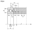
- FIG. 4 is a diagram showing an arrangement example when the arrangement in the axial direction of the heat flow sensor 11a is changed.
- the heat flow sensor 11a1 is arranged at a position where the distance L from the center of the bearing 5a is the “predetermined value L1”, and the distance L from the center of the bearing 5a is the “predetermined value L2”.
- the heat flow sensor 11a2 arranged at the position where the bearing 5a is located, and the heat flow sensor 11a3 arranged at the position where the distance L from the center of the bearing 5a becomes the “predetermined value L3” are shown.
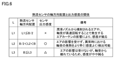
- the predetermined value L1 is L1 ⁇ B / 2, and does not satisfy the above relational expressions (1) and (2).
- the predetermined value L2 is B / 2 ⁇ L2 ⁇ B, and satisfies the above relational expressions (1) and (2).
- the predetermined value L3 is L3 ⁇ B, and the above relational expression (1) is satisfied, but the relational expression (2) is not satisfied.
- FIG. 5 shows the reproduction test conditions of the bearing abnormality.
- a very small amount of lubricating oil was injected into the rolling bearing only when the spindle was installed, creating a situation in which abnormalities are likely to occur in the test bearing.
- FIG. 6 shows the axial arrangement of each heat flow sensor (distances L1 to L3 from the center of the bearing 5a) and the output sensitivity of each heat flow sensor obtained by the reproduction test performed under the test conditions shown in FIG. Show the relationship.
- the heat flow sensor 11a according to the present embodiment is arranged at a position satisfying the above-mentioned relational expressions (1) and (2). Therefore, the sensitivity of the heat flow sensor 11a can be improved even in an environment where the air flow in the bearing 5a changes due to the rotation of the bearing 5a or the injection of the lubrication nozzle.
- the heat flow sensor 11b according to the present embodiment is also arranged at a position satisfying the above-mentioned relational expressions (1) and (2). Therefore, the sensitivity of the heat flow sensor 11b can also be improved.
- "B" is the width dimension (axial length) of the bearing 5b
- "L” is from the center of the bearing 5b. The distance to the center of the heat flow sensor 11b is shown.
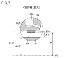
- FIG. 7 is a diagram showing an example of the radial arrangement of the heat flow sensor 11b (the radial direction of the rotation axis P0). Note that FIG. 7 is a partially enlarged view showing the details of the portion C in FIG. 2.
- the heat flow sensor 11b according to the present embodiment is arranged at a position satisfying the following relational expression (3).
- the heat flow sensor 11b according to the present embodiment is arranged at a position satisfying the following relational expression (4).
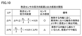
- FIG. 8 is a diagram showing an arrangement example of the heat flow sensor 11b1 in which the distance ⁇ P1 to the outer diameter surface 6iA of the inner ring spacer 6i is (Do / 2-di / 2) ⁇ 0.25 or less.
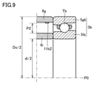
- FIG. 9 is a diagram showing an arrangement example of the heat flow sensor 11b2 in which the distance ⁇ P2 to the outer diameter surface 6iA of the inner ring spacer 6i is larger than (Do / 2-di / 2) ⁇ 0.25.
- FIG. 10 shows the relationship between the radial arrangement of the heat flow sensors 11b1 and 11b2 and the output sensitivity of the heat flow sensors 11b1 and 11b2 obtained by the reproduction test.
- the heat flow sensor 11b according to the present embodiment is arranged at a position satisfying the above-mentioned relational expressions (3) and (4). Therefore, the sensitivity of the heat flow sensor 11b can be improved.
- the heat flow sensor 11a is also arranged at a position satisfying the above-mentioned relational expressions (3) and (4). Therefore, the sensitivity of the heat flow sensor 11a can also be improved.
- "P" is the distance from the rotation axis P0 to the heat flow sensor 11a
- " ⁇ P” is the outer diameter of the inner ring spacer 6i. It represents the distance from the surface 6iA to the heat flow sensor 11a.
- FIG. 11 is a diagram showing an example of arrangement of the heat flow sensor 11b in the circumferential direction (circumferential direction of the rotation axis P0). 11 is a cross-sectional view taken along the line XI-XI in FIG.
- the heat flow sensor 11b according to the present embodiment is arranged at a position satisfying the following relational expression (5).
- ⁇ represents the arrangement angle (angle from the lubrication nozzle to the center of the heat flow sensor) in the circumferential direction with respect to the lubrication nozzle of the lubricating oil supply path 67b. Note that ⁇ is represented as a plus (+) clockwise.
- the heat flow sensor 11b is arranged on the rear side of the inner ring spacer 6i in the rotation direction with respect to the lubrication nozzle. Therefore, for example, when the rotation direction of the inner ring spacer 6i is counterclockwise (-), it is desirable to arrange the heat flow sensor 11b on the rear side in the counterclockwise direction, that is, in the range of 0 ° ⁇ ⁇ 180 °. .. Note that FIG. 11 shows an example in which the arrangement angle ⁇ is about 110 °.
- the heat flow sensor 11b according to the present embodiment is arranged at a position satisfying the following relational expression (6).
- ⁇ represents the angle in the circumferential direction from the center of the exhaust port 6ge to the center of the heat flow sensor 11b.
- the relational expression (6) means that the magnitude (absolute value) of the angle in the circumferential direction from the center of the exhaust port 6ge to the center of the heat flow sensor 11b is less than 90 °.
- FIG. 12 is a diagram showing an arrangement example when the arrangement of the heat flow sensor in the circumferential direction is changed.
- the heat flow sensor having the arrangement angles ⁇ with respect to the lubrication nozzle as the predetermined angles ⁇ 1, ⁇ 2, ⁇ 3, and ⁇ 4, respectively, and the angle ⁇ with respect to the center of the exhaust port 6ge are the predetermined angles.
- a heat flow sensor that becomes ⁇ 1 is shown.
- the predetermined angle ⁇ 1 is ⁇ 15 ° ⁇ 1 ⁇ 0 °, and does not satisfy the above relational expressions (5) and (6).
- the predetermined angle ⁇ 2 is 0 ° ⁇ 2 ⁇ 15 °, and does not satisfy the above relational expressions (5) and (6).
- the predetermined angle ⁇ 3 is ⁇ 90 ° ⁇ 3 ⁇ -15 °, and the above relational expression (5) is satisfied, but the relational expression (6) is not satisfied.
- the predetermined angle ⁇ 4 is 15 ° ⁇ 4 ⁇ 90 °, and the above relational expressions (5) and (6) are satisfied.
- the predetermined angle ⁇ 1 is ⁇ 90 ° ⁇ 1 ⁇ 90 °, and the above relational expressions (5) and (6) are satisfied.
- FIG. 13 shows the relationship between the circumferential arrangement of each heat flow sensor and the output sensitivity of each heat flow sensor obtained by the reproduction test.
- the cooling structure is provided in the outer ring spacer 6g in which the heat flow sensors 11a and 11b are arranged.
- FIG. 14 is a diagram showing an example of a cooling structure provided in the outer ring spacer 6 g.
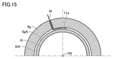
- FIG. 15 is a cross-sectional view taken along the line XV-XV of FIG.
- two refrigerant paths 71 and 72 are provided in the housing 3, and a spiral groove 73 is provided on the outer diameter surface of the outer ring spacer 6 g.
- One end and the other end of the spiral groove 73 are connected to the refrigerant paths 71 and 72, respectively.
- a refrigerant (oil, water, compressed air, etc.) flows into the spiral groove 73 from one of the refrigerant paths 71 and 72, and the refrigerant flowing in the spiral groove 73 is discharged to the other of the refrigerant paths 71 and 72. Therefore, the spiral groove 73 functions as a refrigerant flow path for the outer ring spacer 6 g.
- the heat flow sensor 11a is connected to the outside of the outer ring spacer 6g by the wiring W.
- the outer ring spacer 6g includes not only the heat flow sensors 11a and 11b and the spiral groove 73, but also a wireless transmitter that transmits the data acquired by the sensor to the outside, and a self-power generation device that drives the sensor and the wireless transmitter.
- a control device including a signal processing unit such as temporary storage of data acquired by a sensor or conversion of data may be provided.
- FIG. 16 is a diagram showing a modified example of the arrangement of the heat flow sensor.
- protrusions 7a and 7b protruding from the axial side surface between the inner and outer rings are added to the outer ring spacer 6g on the fixed side, and the heat flow sensor 11a is added to one of the protrusions 7a. Is installed.
- the heat flow sensor 11b may be similarly arranged on the other protruding portion 7b.
- the heat generation source is the rolling element contact portion of the fixed side raceway ring of the rolling bearing, but when the heat flow sensor is installed on the fixed side raceway ring, there is a concern that the processing cost of the fixed side raceway ring becomes high.
- the heat flow sensor is installed on the protruding portions 7a and 7b of the fixed side spacer, this problem can be solved and the heat flow sensor can be easily installed. Further, since the heat flow sensors 11a and 11b are installed on the protruding portions 7a and 7b protruding between the inner and outer rings, it is possible to directly detect the temperature change inside the bearing during operation.
- the protrusions 7a and 7b may also serve as nozzles for discharging air oil-lubricated lubricating oil to the bearings 5a and 5b.
- the heat flow sensor since the heat flow sensor can be installed by using the existing nozzle that discharges the lubricating oil, the cost can be reduced as compared with the case of providing a dedicated component for installing the heat flow sensor, for example.
- FIG. 17 is a diagram showing another modification of the arrangement of the heat flow sensor. 1 and 2 show an example in which the heat flow sensors 11a and 11b are installed at the axial end (near the bearing 5) on the inner diameter surface of the outer ring spacer 6g. However, as shown in FIG. 17, the heat flow sensor 11 may be installed at the central portion in the axial direction on the inner diameter surface of the outer ring spacer 6 g.
- the heat flow sensor may be arranged in the housing 3 or the front lid (not shown), and the housing 3 or the front lid may be provided with a cooling structure, a wireless transmitter, a self-power generation device, and a control device.
- 1 Spindle device 2 Outer cylinder, 3 Housing, 4 Spindle, 5,5a, 5b bearing, 5ga, 5gb outer ring, 5ia, 5ib inner ring, 6 spacer, 6g outer ring spacer, 6gA inner diameter surface, 6ge exhaust port, 6i inner ring Spacing, 6iA outer diameter surface, 7a, 7b protrusion, 11a, 11b heat flow sensor, 30 bearing device, 67a, 67b lubricating oil supply path, 71 refrigerant path, 73 groove, P0 rotary shaft, Rta, Rtb cage, Ta , Tb rolling element, W wiring.
Landscapes
- Engineering & Computer Science (AREA)
- General Engineering & Computer Science (AREA)
- Mechanical Engineering (AREA)
- Chemical & Material Sciences (AREA)
- Combustion & Propulsion (AREA)
- Oil, Petroleum & Natural Gas (AREA)
- Rolling Contact Bearings (AREA)
- Turning (AREA)
Abstract
Description
・軸受内部に封入された潤滑グリースの劣化
・軸受転がり部へのクーラントまたは水の浸入、あるいは異物の侵入
・過大な予圧、つまり転がり部の接触面圧の増大による油膜切れ
上記による軸受の過度の昇温を防止すべく、軸受に隣接した間座に潤滑給油ポンプと非接触式の温度センサを内蔵し、温度センサによる軸受潤滑部の温度測定値に応じて、潤滑給油ポンプにて軸受内部に潤滑油を給油する技術が特開2017-26078号公報(特許文献1)に開示されている。
(8) ある態様においては、回転体は、工作機械の主軸である。
本出願人は、工作機械主軸スピンドルを模した試験機に実施形態に係る軸受装置を組込み、主軸4の回転速度を加速および減速したときの熱流束、温度、回転速度の関係を評価する加減速試験を行なった。
上述の図2には、本実施の形態による熱流センサ11a,11bの軸方向(回転軸P0に沿う方向)の配置例が示される。本実施の形態による熱流センサ11aは、下記の関係式(1)を満たす位置に配置される。
関係式(1)において、「B」は軸受5aの幅寸法(軸方向の長さ)、「L」は軸受5aの中心から熱流センサ11aの中心までの距離、「M」は、外輪間座6gの幅寸法(軸方向の長さ)を表わす。
関係式(2)は、関係式(1)の「M」を「B」に置き換えたものである。
図7は、熱流センサ11bの径方向(回転軸P0の径方向)の配置の一例を示す図である。なお、図7は、図2におけるC部の詳細を示す部分拡大図である。
関係式(3)において、「do」は内輪間座6iの外径、「Di」は外輪間座6gの内径、「P」は回転軸P0から熱流センサ11bまでの距離を表わす。
関係式(4)において、「Do」は外輪間座6gの外径、「di」は内輪間座6iの内径、「ΔP」は内輪間座6iの外径面6iAから熱流センサ11bまでの距離(=P-do/2)を表わす。関係式(4)は、内輪間座6iの外径面6iAから熱流センサ11bまでの距離が、0よりも大きく、内輪間座6iの内径面と外輪間座6gの外径面との間の距離(=Do/2-di/2、すなわち間座6の径方向の寸法)の25%以下であることを意味する。
図11は、熱流センサ11bの周方向(回転軸P0の周方向)の配置の一例を示す図である。なお、図11は、図2におけるXI-XI断面図である。本実施の形態による熱流センサ11bは、下記の関係式(5)を満たす位置に配置される。
関係式(5)において、「θ」は、潤滑油供給路67bの潤滑ノズルを基準としたときの周方向の配置角(潤滑ノズルから熱流センサの中心までの角度)を表わす。なお、θは、時計周りをプラス(+)として表わされる。
関係式(6)において、「β」は、排気口6geの中心から熱流センサ11bの中心までの周方向の角度を表わす。関係式(6)は、排気口6geの中心から熱流センサ11bの中心までの周方向の角度の大きさ(絶対値)が90°未満であることを意味する。なお、図11に示す例では、排気口6geの中心がθ=180°となるように排気口6geが配置されている。すなわち、潤滑ノズルは、外輪間座6gにおける排気口6geとは反対側の領域に設けられる。
上述したように、本実施の形態においては、熱流センサ11a,11bが配置される外輪間座6gに冷却構造が設けられる。
図16は、熱流センサの配置の変形例を示す図である。本変形例では、図16に示すように、固定側である外輪間座6gに、軸方向側面から内外輪間に突出する突出部7a,7bが付加され、一方の突出部7aに熱流センサ11aが設置される。この場合、図示しないが、もう一方の突出部7bにも、同様に熱流センサ11bを配置するとよい。
Claims (8)
- 内輪、外輪、転動体、および保持器を含み、回転体を回転軸回りに回転可能に支持する軸受と、
前記内輪に隣接する内輪間座と前記外輪に隣接する外輪間座とを含む間座と、
前記間座および前記軸受の周辺部品のいずれかに設けられる熱流センサとを備え、
前記軸受の中心から前記熱流センサの中心までの前記回転軸に沿う方向の距離は、前記軸受の前記回転軸に沿う方向の寸法の0.5倍よりも大きく1倍未満である、軸受装置。 - 前記内輪間座の外径面から前記熱流センサまでの前記回転軸の径方向の距離は、前記内輪間座の内径面と前記外輪間座の外径面との間の距離の25%以下である、請求項1に記載の軸受装置。
- 前記熱流センサは、前記外輪間座の内径面に設けられ、
前記外輪間座には、潤滑用のエアオイルを排出するための排気口が設けられ、
前記排気口の中心から前記熱流センサの中心までの前記回転軸の周方向の角度の大きさは90°未満である、請求項1または2に記載の軸受装置。 - 前記外輪間座には、前記エアオイルを噴射するためのノズルが設けられ、
前記ノズルは、前記外輪間座における前記排気口とは反対側の領域に設けられる、請求項3に記載の軸受装置。 - 内輪、外輪、転動体、および保持器を含み、回転体を回転軸回りに回転可能に支持する軸受と、
前記内輪に隣接する内輪間座と前記外輪に隣接する外輪間座とを含む間座と、
前記間座および前記軸受の周辺部品のいずれかに設けられる熱流センサとを備え、
前記内輪間座の外径面から前記熱流センサまでの前記回転軸の径方向の距離は、前記内輪間座の内径面と前記外輪間座の外径面との間の距離の25%以下である、軸受装置。 - 内輪、外輪、転動体、および保持器を含み、回転体を回転軸回りに回転可能に支持する軸受と、
前記内輪に隣接する内輪間座と前記外輪に隣接する外輪間座とを含む間座と、
前記間座および前記軸受の周辺部品のいずれかに設けられる熱流センサとを備え、
前記熱流センサは、前記外輪間座の内径面に設けられ、
前記外輪間座には、潤滑用のエアオイルを排出するための排気口が設けられ、
前記排気口の中心から前記熱流センサの中心までの前記回転軸の周方向の角度の大きさは90°未満である、軸受装置。 - 前記外輪間座に冷媒流路が設けられる、請求項1~6のいずれかに記載の軸受装置。
- 前記回転体は、工作機械の主軸である、請求項1~7のいずれかに記載の軸受装置。
Priority Applications (4)
| Application Number | Priority Date | Filing Date | Title |
|---|---|---|---|
| KR1020237009561A KR20230066570A (ko) | 2020-09-16 | 2021-09-08 | 베어링 장치 |
| CN202180063323.3A CN116323051B (zh) | 2020-09-16 | 2021-09-08 | 轴承装置 |
| US18/022,734 US12157194B2 (en) | 2020-09-16 | 2021-09-08 | Bearing apparatus |
| EP21869260.6A EP4215301B1 (en) | 2020-09-16 | 2021-09-08 | Bearing apparatus |
Applications Claiming Priority (2)
| Application Number | Priority Date | Filing Date | Title |
|---|---|---|---|
| JP2020-155151 | 2020-06-19 | ||
| JP2020155151A JP7756486B2 (ja) | 2020-09-16 | 2020-09-16 | 軸受装置 |
Publications (1)
| Publication Number | Publication Date |
|---|---|
| WO2022059573A1 true WO2022059573A1 (ja) | 2022-03-24 |
Family
ID=80775994
Family Applications (1)
| Application Number | Title | Priority Date | Filing Date |
|---|---|---|---|
| PCT/JP2021/032960 Ceased WO2022059573A1 (ja) | 2020-09-16 | 2021-09-08 | 軸受装置 |
Country Status (7)
| Country | Link |
|---|---|
| US (1) | US12157194B2 (ja) |
| EP (1) | EP4215301B1 (ja) |
| JP (1) | JP7756486B2 (ja) |
| KR (1) | KR20230066570A (ja) |
| CN (1) | CN116323051B (ja) |
| TW (1) | TW202217164A (ja) |
| WO (1) | WO2022059573A1 (ja) |
Cited By (2)
| Publication number | Priority date | Publication date | Assignee | Title |
|---|---|---|---|---|
| CN115722689A (zh) * | 2022-11-30 | 2023-03-03 | 四川省兴旺达精密机电有限公司 | 一种机床主轴 |
| WO2023201969A1 (zh) * | 2022-04-21 | 2023-10-26 | 洛阳轴承研究所有限公司 | 隔圈组件及轴承组件 |
Families Citing this family (1)
| Publication number | Priority date | Publication date | Assignee | Title |
|---|---|---|---|---|
| CN121408370A (zh) * | 2025-12-30 | 2026-01-27 | 人本股份有限公司 | 角接触球轴承及其热检测反馈控制系统 |
Citations (4)
| Publication number | Priority date | Publication date | Assignee | Title |
|---|---|---|---|---|
| JP2016166832A (ja) | 2015-03-10 | 2016-09-15 | 株式会社日本自動車部品総合研究所 | 熱流束センサ |
| JP2017026078A (ja) | 2015-07-24 | 2017-02-02 | 株式会社ジェイテクト | 軸受装置 |
| WO2019159838A1 (ja) * | 2018-02-13 | 2019-08-22 | Ntn株式会社 | 軸受装置およびスピンドル装置 |
| WO2020166542A1 (ja) * | 2019-02-12 | 2020-08-20 | Ntn株式会社 | 軸受装置およびスピンドル装置 |
Family Cites Families (8)
| Publication number | Priority date | Publication date | Assignee | Title |
|---|---|---|---|---|
| JP4269674B2 (ja) * | 2002-12-18 | 2009-05-27 | 日本精工株式会社 | 転がり軸受ユニット用荷重測定装置 |
| CN204262903U (zh) * | 2014-11-11 | 2015-04-15 | 重庆丰德数控机床有限公司 | 一种机床主轴实时测量装置 |
| DE102017210752A1 (de) * | 2017-06-27 | 2018-12-27 | Aktiebolaget Skf | Vorspannungsanpassung in einer Lageranordnung |
| JP7362239B2 (ja) * | 2018-02-13 | 2023-10-17 | Ntn株式会社 | 軸受装置およびスピンドル装置 |
| JP6967495B2 (ja) * | 2018-09-03 | 2021-11-17 | Ntn株式会社 | 軸受装置 |
| JP2020060227A (ja) * | 2018-10-09 | 2020-04-16 | Ntn株式会社 | 軸受装置 |
| DE112019005429T5 (de) * | 2018-10-31 | 2021-07-15 | Ntn Corporation | Lagervorrichtung |
| JP2020133889A (ja) * | 2019-02-12 | 2020-08-31 | Ntn株式会社 | 軸受装置およびスピンドル装置 |
-
2020
- 2020-09-16 JP JP2020155151A patent/JP7756486B2/ja active Active
-
2021
- 2021-09-08 EP EP21869260.6A patent/EP4215301B1/en active Active
- 2021-09-08 WO PCT/JP2021/032960 patent/WO2022059573A1/ja not_active Ceased
- 2021-09-08 KR KR1020237009561A patent/KR20230066570A/ko active Pending
- 2021-09-08 US US18/022,734 patent/US12157194B2/en active Active
- 2021-09-08 CN CN202180063323.3A patent/CN116323051B/zh active Active
- 2021-09-10 TW TW110133712A patent/TW202217164A/zh unknown
Patent Citations (4)
| Publication number | Priority date | Publication date | Assignee | Title |
|---|---|---|---|---|
| JP2016166832A (ja) | 2015-03-10 | 2016-09-15 | 株式会社日本自動車部品総合研究所 | 熱流束センサ |
| JP2017026078A (ja) | 2015-07-24 | 2017-02-02 | 株式会社ジェイテクト | 軸受装置 |
| WO2019159838A1 (ja) * | 2018-02-13 | 2019-08-22 | Ntn株式会社 | 軸受装置およびスピンドル装置 |
| WO2020166542A1 (ja) * | 2019-02-12 | 2020-08-20 | Ntn株式会社 | 軸受装置およびスピンドル装置 |
Non-Patent Citations (1)
| Title |
|---|
| See also references of EP4215301A4 |
Cited By (2)
| Publication number | Priority date | Publication date | Assignee | Title |
|---|---|---|---|---|
| WO2023201969A1 (zh) * | 2022-04-21 | 2023-10-26 | 洛阳轴承研究所有限公司 | 隔圈组件及轴承组件 |
| CN115722689A (zh) * | 2022-11-30 | 2023-03-03 | 四川省兴旺达精密机电有限公司 | 一种机床主轴 |
Also Published As
| Publication number | Publication date |
|---|---|
| JP2022049111A (ja) | 2022-03-29 |
| EP4215301A4 (en) | 2024-11-13 |
| CN116323051B (zh) | 2026-04-07 |
| TW202217164A (zh) | 2022-05-01 |
| EP4215301B1 (en) | 2026-04-22 |
| JP7756486B2 (ja) | 2025-10-20 |
| CN116323051A (zh) | 2023-06-23 |
| US12157194B2 (en) | 2024-12-03 |
| EP4215301A1 (en) | 2023-07-26 |
| KR20230066570A (ko) | 2023-05-16 |
| US20230311257A1 (en) | 2023-10-05 |
Similar Documents
| Publication | Publication Date | Title |
|---|---|---|
| JP5564963B2 (ja) | 軸受装置及び工作機械の主軸装置 | |
| WO2022059573A1 (ja) | 軸受装置 | |
| CA2884602A1 (en) | Rotary machine, bearing and method for manufacturing a rotary machine | |
| JP6662499B1 (ja) | 軸受装置及び工作機械の主軸装置 | |
| CN113453826B (zh) | 轴承装置和主轴装置 | |
| JP2017180819A (ja) | 軸受装置 | |
| JP7543649B2 (ja) | 算出方法、軸受装置及び工作機械の主軸装置 | |
| JP5842965B2 (ja) | 荷重センサ付き軸受装置を具備した工作機械の主軸装置 | |
| EP3848597B1 (en) | Bearing device | |
| WO2020195563A1 (ja) | 軸受装置 | |
| WO2019159838A1 (ja) | 軸受装置およびスピンドル装置 | |
| JP2011169356A (ja) | 潤滑機能付き転がり軸受装置およびシール部材つぶし代設定方法 | |
| JP2021014885A (ja) | 軸受装置及びスピンドル装置 | |
| JPH03163214A (ja) | 軸受装置 | |
| JP2024110470A (ja) | 軸受装置およびスピンドル装置 | |
| JP2024066772A (ja) | 軸受装置 |
Legal Events
| Date | Code | Title | Description |
|---|---|---|---|
| 121 | Ep: the epo has been informed by wipo that ep was designated in this application |
Ref document number: 21869260 Country of ref document: EP Kind code of ref document: A1 |
|
| ENP | Entry into the national phase |
Ref document number: 20237009561 Country of ref document: KR Kind code of ref document: A |
|
| NENP | Non-entry into the national phase |
Ref country code: DE |
|
| ENP | Entry into the national phase |
Ref document number: 2021869260 Country of ref document: EP Effective date: 20230417 |
|
| WWG | Wipo information: grant in national office |
Ref document number: 2021869260 Country of ref document: EP |