WO2022064672A1 - Dispositif de station de base, système de communication sans fil et procédé de communication sans fil - Google Patents
Dispositif de station de base, système de communication sans fil et procédé de communication sans fil Download PDFInfo
- Publication number
- WO2022064672A1 WO2022064672A1 PCT/JP2020/036539 JP2020036539W WO2022064672A1 WO 2022064672 A1 WO2022064672 A1 WO 2022064672A1 JP 2020036539 W JP2020036539 W JP 2020036539W WO 2022064672 A1 WO2022064672 A1 WO 2022064672A1
- Authority
- WO
- WIPO (PCT)
- Prior art keywords
- base station
- wireless communication
- station device
- uplink
- mobile base
- Prior art date
- Legal status (The legal status is an assumption and is not a legal conclusion. Google has not performed a legal analysis and makes no representation as to the accuracy of the status listed.)
- Ceased
Links
Images




Classifications
-
- H—ELECTRICITY
- H04—ELECTRIC COMMUNICATION TECHNIQUE
- H04W—WIRELESS COMMUNICATION NETWORKS
- H04W16/00—Network planning, e.g. coverage or traffic planning tools; Network deployment, e.g. resource partitioning or cells structures
- H04W16/14—Spectrum sharing arrangements between different networks
-
- H—ELECTRICITY
- H04—ELECTRIC COMMUNICATION TECHNIQUE
- H04W—WIRELESS COMMUNICATION NETWORKS
- H04W88/00—Devices specially adapted for wireless communication networks, e.g. terminals, base stations or access point devices
- H04W88/02—Terminal devices
- H04W88/06—Terminal devices adapted for operation in multiple networks or having at least two operational modes, e.g. multi-mode terminals
Definitions
- the present invention relates to a base station device, a wireless communication system, and a wireless communication method.
- NR New Radio
- 5G Fifth Generation
- NR New Radio
- LTE Long Term Evolution
- URLLC Ultra-Reliable and Low Latency Communication
- IoT Internet of Things
- the passenger terminal device when providing Wi-Fi (Wireless Fidelity) services to passengers on board an aircraft or the like, the passenger terminal device is a base station for satellites on the ground via an access point installed on the aircraft or the like and an artificial satellite. It was possible to communicate with the device and connect to the Internet, etc.
- Wi-Fi Wireless Fidelity
- NR has proposed an anti-aircraft (ATG: Air to Ground) (hereinafter also referred to as "ATG”) network that directly communicates between an access point and a base station device on the ground without going through an artificial satellite.
- ATG Air to Ground
- the access points installed on aircraft and the base station equipment installed on the ground will be dedicated from the viewpoint of power and antenna directivity.
- the frequency band used between the access point and the base station device is not a dedicated one, and may share the frequency band used in the existing terrestrial networks (TN: Terrestrial Networks).
- the wireless communication of the uplink from the access point to the terrestrial base station device interferes with the wireless communication between the base station device and the terminal device in the terrestrial network. There was a risk that it would end up.
- the present invention has been made in view of such circumstances, and one of the objects of the present invention is to provide a base station device, a wireless communication system, and a wireless communication method capable of suppressing interference due to uplink wireless communication. do.
- the base station device is a base station device that is installed on the ground and performs wireless communication with a communication device provided on a flying object, and is an uplink wireless communication from the communication device to the base station device. It is provided with a transmission unit which is arranged around the base station device and transmits the uplink information related to the above to the mobile base station device which wirelessly communicates with the terminal device using the same frequency band as the base station device.
- the wireless communication system is installed on the ground and is arranged in the vicinity of an air-to-ground base station device that performs wireless communication with a communication device provided on a flying object and an air-to-ground base station device.
- a mobile base station device that performs wireless communication with a terminal device using the same frequency band as the base station device is provided, and the air-to-ground base station device is an uplink wireless communication from the communication device to the air-to-ground base station device.
- the uplink information relating to the above is transmitted to the mobile base station apparatus, and the mobile base station apparatus suppresses interference due to the uplink wireless communication based on the uplink information.
- the wireless communication method is a wireless communication method used for a base station device that is installed on the ground and performs wireless communication with a communication device provided on a flying object, from a communication device to a base station device. Includes a step of transmitting uplink information about the uplink wireless communication of the base station device to a mobile base station device that is arranged around the base station device and communicates wirelessly with the terminal device using the same frequency band as the base station device. ..
- FIG. 1 is a configuration diagram showing an example of a schematic configuration of a wireless communication system according to an embodiment.
- FIG. 2 is a configuration diagram showing an example of the hardware configuration of the terminal device and the base station device in one embodiment.
- FIG. 3 is a diagram for explaining the structure of a wireless frame used by the wireless communication system in one embodiment.
- FIG. 4 is a diagram for explaining the frequency bandwidth used by the wireless communication system in one embodiment.
- FIG. 5 is a configuration diagram showing a wireless communication system according to a specific example of the embodiment.
- FIG. 6 is a configuration diagram showing a wireless communication system according to a specific example of the embodiment.
- FIG. 7 is a configuration diagram showing an example of a functional block configuration of the ATG base station apparatus in one embodiment.
- FIG. 8 is a configuration diagram showing an example of a functional block configuration of the mobile base station apparatus according to the embodiment.
- FIG. 9 is a time chart for explaining an example of the processing procedure performed by the wireless communication system in one embodiment.
- FIG. 10 is a flowchart for explaining an example of a processing procedure performed by the ATG base station apparatus in one embodiment.
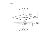
- FIG. 11 is a flowchart for explaining an example of a processing procedure performed by the mobile base station apparatus in one embodiment.
- FIG. 1 is a configuration diagram showing an example of a schematic configuration of a wireless communication system 100 according to an embodiment.
- the wireless communication system 100 includes a terminal device 10-1 to a terminal device 10-m, a base station device 50-1 to a base station device 50-n, and a core network device 90. It is composed.
- the wireless communication system 100 is, for example, a wireless communication system for NR. It should be noted that the present invention is applicable as long as it is a wireless communication system including at least a terminal device and a base station device, and is not limited to those targeting NR. For example, the present invention is also applicable to LTE and LTE-Advanced. It can also be applied to a wireless communication system in which NR is used as a part of the wireless communication system.
- LTE and LTE-Advanced are also referred to as E-UTRA (Evolved Universal Terrestrial Radio Access), but their meanings are the same.
- the area (cover area) formed by the base station apparatus is referred to as a cell, and E-UTRA and NR are cellular communication systems constructed by a plurality of cells.
- E-UTRA and NR are cellular communication systems constructed by a plurality of cells.
- TDD Time Division Duplex
- FDD Frequency Division Duplex
- the terminal device 10-1 to the terminal device 10-m are wirelessly connected to any one of the base station device 50-1 to the base station device 50-n, respectively. Further, each of the terminal devices 10-1 to the terminal device 10-m may be wirelessly connected to two or more of the base station devices 50-1 to the base station device 50-n at the same time.
- E-UTRA or NR can be used for the base station apparatus 50-1 to the base station apparatus 50-n, respectively.
- the base station apparatus 50-1 may use the NR and the base station apparatus 50-n may use the E-UTRA, and vice versa.
- the base station device in E-UTRA is called eNB (evolved NodeB), and the base station device in NR is called gNB (g-NodeB).
- the term “base station device” means that both eNB and gNB are included. Further, the terminal device in E-UTRA and NR is referred to as UE (User Equipment).
- the base station device gNB in the NR may be connected to the terminal device by using a part of the bandwidth of the frequency band used thereof (BWP: BandWidthPart).
- BWP BandWidthPart
- FIG. 1 illustrates terminal devices 10-1 to 10-m as terminal devices in the m range (m is an integer of 2 or more). In the following description, when these m-unit terminal devices are described without distinction, a part of the reference numerals is omitted and the term "terminal device 10" is simply referred to. Further, FIG. 1 illustrates the base station devices 50-1 to the base station devices 50-n as n base station devices (n is an integer of 2 or more). In the following description, when these n base station devices are described without distinction, a part of the reference numerals is omitted and the term “base station device 50” is simply referred to.
- the terminal device 10 may be connected to the base station device 50 in cell units, for example, and may be connected using a plurality of cells, for example, carrier aggregation.
- the base station device to be initially connected is the master node (MN: MasterNode), and the base station device to be additionally connected is used. It is called a secondary node (SN: Secondary Node).
- MN MasterNode
- SN Secondary Node
- the base station devices are connected by a base station interface.
- the base station device 50 and the core network device 90 are connected by a core interface.
- the base station interface is used for exchanging control signals necessary for handover and cooperation operation between base station devices.
- the core network device 90 has, for example, a base station device 50 under its control, and mainly handles load control between base station devices, call (paging) of the terminal device 10, and movement control such as location registration.
- the NR defines AMF (Access and Mobility Management Function) for managing mobility and SMF (Session Management Function) for managing sessions as a function group of the control plane (C-plane) in the core network device 90.
- AMF Access and Mobility Management Function
- SMF Session Management Function
- C-plane control plane
- E-UTRA defines MME (Mobility Management Entity) corresponding to AMF.
- FIG. 1 shows an example in which the core network device 90 is composed of one device, but the present invention is not limited to this.
- the core network device may include a server, a gateway, and the like, and may be composed of a plurality of devices.
- the terminal device 10 and the base station device 50 send and receive RRC messages in the radio resource control (RRC: RadioResourceControl) layer, and proceed with session processing (also referred to as a connection sequence).
- RRC RadioResourceControl
- session processing also referred to as a connection sequence.
- the terminal device 10 changes from the idle state (RRCIdle) to the connected state to the base station device 50 (RRCConnected).
- the idle state corresponds to the standby state of the terminal device 10.
- the terminal device 10 and the base station device 50 transmit and receive a MAC control element (MAC CE: MAC Control Element) in the medium access control (MAC: Medium Access Control) layer.
- the RRC message is transmitted as an RRC PDU (Protocol Data Unit), and the mapped logical channels are a common control channel (CCCH: Common Control Channel), an individual control channel (DCCH: Dedicated Control Channel), and a paging control channel (PCCH:). Paging Control Channel), Broadcast Control Channel (BCCH: Broadcast Control Channel), or Multicast Control Channel (MCCH: Multicast Control Channel) is used.
- the MAC CE is transmitted as a MAC PDU (or MAC subPDU).
- a MAC subPDU is equivalent to a service data unit (SDU: ServiceDataUnit) in the MAC layer plus, for example, an 8-bit header, and a MAC PDU contains one or more MAC subPDUs.
- SDU ServiceDataUnit
- PBCH Physical Broadcast Channel
- PSS Primary Synchronization Signal
- SSS Secondary Synchronization Signal
- DMRS Demodulation Reference Signal
- PBCH Physical broadcast channel
- the physical broadcast channel (PBCH) is transmitted from the base station device to the terminal device and is used to notify a common parameter (system information) in a cell under the base station device.
- System information is further classified into a master information block (MIB: Master Information Block) and a system information block (SIB: System Information Block).
- MIB Master Information Block
- SIB System Information Block
- the system information block is further subdivided into SIB1, SIB2, ..., And transmitted.
- the system information includes information necessary for connecting to the cell.
- the MIB includes information such as a system frame number and information indicating whether or not to camp on the cell.
- SIB1 contains parameters for calculating cell quality (cell selection parameters), cell-common channel information (random access control information, PUCCH control information, PUSCH control information), scheduling information of other system information, and the like.
- the physical broadcast channel (PBCH) is a set of a synchronization signal block (SSB: Synchronization Signal Block (or SS / PBSH)) composed of a primary synchronization signal (PSS) and a secondary synchronization signal (SSS). Is transmitted periodically.
- SSB Synchronization Signal Block
- PSS primary synchronization signal
- SSS secondary synchronization signal
- the system information notified by the physical notification channel (PBCH) or the like is also called “system notification information” or “notification information”.
- PBCH physical notification channel
- camping on to a cell means that the terminal device has completed cell selection and / or cell reselection, and the terminal device has selected a cell for monitoring system notification information and paging information. It means to become.
- the terminal device establishes the aforementioned RRC connection with the base station device forming the camp-on cell.
- the primary sync signal is used by the terminal device to synchronize the receive symbol timing and frequency of the downlink signal of the base station device.
- the primary synchronization signal is a signal that the terminal device first tries to detect in the procedure for detecting the cell of the base station device (hereinafter, also referred to as “cell search procedure”).
- cell search procedure As the primary synchronization signal (PSS), three types of signals "0" to "2" are repeatedly used based on the physical cell ID.
- the physical cell ID is a physical cell identifier, and 504 IDs are used in E-UTRA, and 1008 IDs are used in NR.
- the secondary sync signal (SSS) is used by the terminal device to detect the physical ID of the base station device.
- the secondary synchronization signal (SSS) is a signal for the terminal device to detect the physical cell ID in the cell search procedure.
- SSS 168 ways of "0" to "167” in E-UTRA and 336 ways of signals from “0" to "335" in NR are repeatedly used based on the physical cell ID. ..
- the physical random access channel (PRACH) is used by the terminal device 10 to transmit a random access preamble to the base station device 50.
- the physical random access channel (PRACH) is generally used in a state where uplink synchronization has not been established between the terminal device 10 and the base station device 50, and transmission timing adjustment information (timing advance) and uplink radio are used. Used for resource requests.
- Information indicating a radio resource capable of transmitting a random access preamble is transmitted to a terminal using broadcast information or an RRC message.
- the physical downlink control channel (PDCCH) is transmitted from the base station apparatus 50 to notify the terminal apparatus 10 of the downlink control information (DCI).
- the downlink control information includes uplink radio resource information (UL credit) that can be used by the terminal device 10 or downlink radio resource information (downlink grant (DL grant)).
- the downlink grant is information indicating the scheduling of the physical downlink shared data channel (PDSCH).
- the uplink grant is information indicating the scheduling of the physical uplink shared channel (PUSCH).
- the physical downlink shared data channel (PDSCH) indicated by the physical downlink control channel (PDCCH) is a random access response and a random access preamble.
- Index information, transmission timing adjustment information, uplink grant, etc. are included.
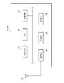
- FIG. 2 is a configuration diagram showing an example of the hardware configuration of the terminal device 10 and the base station device 50 in one embodiment.
- the terminal device 10 and the base station device 50 include, for example, a processor 21, a memory 22, a storage device 23, a communication device 24, an input device 25, an output device 26, and an antenna 27, respectively.
- the processor 21 is configured to control the operation of each part of the terminal device 10 or the base station device 50.
- the processor 21 is, for example, a CPU (Central Processing Unit), a DSP (Digital Signal Processor), an ASIC (Application Specific Integrated Circuit), a PLD (Programmable Logic Device), an FPGA (Field Programmable Gate Array), and a SoC (System-on-a). -chip) and other integrated circuits are included.
- the memory 22 and the storage device 23 are each configured to store programs, data, and the like.
- the memory 22 is composed of, for example, a ROM (ReadOnlyMemory), an EPROM (ErasableProgrammableROM), an EEPROM (ElectricallyErasableProgrammableROM), and / or a RAM (RandomAccessMemory).
- the storage device 23 is composed of, for example, storage such as an HDD (Hard Disk Drive), an SSD (Solid State Drive) and / or an eMMC (embedded MultiMediaCard).
- the communication device 24 is configured to communicate via a wired and / or wireless network.
- the communication device 24 includes, for example, a network card, a communication module, and the like. Further, the communication device 24 may include an amplifier, an RF (Radio Frequency) device that performs processing related to radio signals, and a BB (BaseBand) device that performs baseband signal processing.
- RF Radio Frequency
- BB BaseBand
- the RF device for example, performs D / A (Digital to Analog) conversion, modulation, frequency conversion, power amplification, etc. on the digital baseband signal received from the BB device, thereby transmitting a wireless signal transmitted from the antenna 27. Generate. Further, the RF device generates a digital baseband signal by performing frequency conversion, demodulation, A / D (Analog to Digital) conversion, etc. on the radio signal received from the antenna 27, and transmits the digital baseband signal to the BB device.
- the BB apparatus performs a process of converting a digital baseband signal into an IP packet and a process of converting an IP packet into a digital baseband signal.
- the input device 25 is configured so that information can be input by a user operation.
- the input device 25 includes, for example, a keyboard, a touch panel, a mouse, and / or a microphone.
- the output device 26 is configured to output information.
- the output device 26 includes, for example, a liquid crystal display, an EL (Electro Luminescence) display, a display device such as a plasma display, and / or a speaker.
- a liquid crystal display for example, a liquid crystal display, an EL (Electro Luminescence) display, a display device such as a plasma display, and / or a speaker.
- EL Electro Luminescence
- the antenna 27 is configured to be able to radiate (radiate) and receive radio waves (electromagnetic waves) in one or a plurality of predetermined frequency bands.
- the antenna 27 may be non-directional, that is, omnidirectional.
- the omnidirectional antenna 27 has approximately equal gains from all directions of 360 degrees in the horizontal plane, in the vertical plane, or both in the horizontal plane and in the non-horizontal plane and in the vertical plane.
- the number of antennas 27 is not limited to one.
- the base station apparatus 50 includes a plurality of antennas, it may be divided into, for example, a transmitting antenna and a receiving antenna. Further, when a plurality of antennas are divided into a transmitting antenna and a receiving antenna, at least one of them may include a plurality of antennas.
- the base station device 50 includes a plurality of transmission / reception antennas or transmission antennas, a beamforming technique described later can be used.
- the terminal device 10 and the base station device 50 include, for example, various sensors such as a GPS (Global Positioning System) receiver, an orientation sensor, a gravity sensor, a temperature sensor, and an acceleration sensor, a fingerprint, and a retina. It may further include at least one of various biometric functions such as an iris, a face, and a voiceprint, various devices such as a camera, a microphone, a speaker, and a light, and an input / output interface including a connection terminal.
- various sensors such as a GPS (Global Positioning System) receiver, an orientation sensor, a gravity sensor, a temperature sensor, and an acceleration sensor, a fingerprint, and a retina. It may further include at least one of various biometric functions such as an iris, a face, and a voiceprint, various devices such as a camera, a microphone, a speaker, and a light, and an input / output interface including a connection terminal.
- GPS Global Positioning System
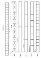
- FIG. 3 is a diagram for explaining the structure of the wireless frame used by the wireless communication system 100 in one embodiment.
- the orthogonal frequency division duplex method (OFDM: Orthogonal Frequency Division Duplex) is adopted as the modulation method.
- the NR supports subcarrier spacing of 30, 60, 120, 240 kHz in addition to the E-UTRA subcarrier spacing of 15 kHz.
- the subcarrier interval indicates the minimum frequency unit.
- the subcarrier interval 240 kHz is supported only in the synchronization signal block, and the subcarrier interval 60 kHz is not supported in the synchronization signal block.
- the radio frame has a length of 10 ms in the time axis direction and is composed of 10 subframes sf1 to sf10.
- Each of the subframes sf1 to sf10 has a length of 1 ms in the time axis direction and is composed of one or a plurality of slots.
- each subframe sf1 to sf10 includes one slot
- each subframe sf1 to sf10 contains two slots and the subcarrier spacing.
- each subframe sf1 to sf10 contains 4 slots, and when the subcarrier spacing is 120 kHz, each subframe sf1 to sf10 contains 8 slots, and when the subcarrier spacing is 240 kHz, each sub The frames sf1 to sf10 include 16 slots. That is, the length of the slot in the time axis direction differs depending on the subcarrier interval.
- each slot is composed of 14 OFDM symbols sy1 to sy14 regardless of the subcarrier interval.
- the OFDM symbol indicates the minimum time unit.
- a resource block is composed of 14 OFDM symbols in the time axis direction and 12 subcarriers in the frequency axis direction.
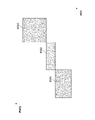
- FIG. 4 is a diagram for explaining a frequency bandwidth used by the wireless communication system 100 in one embodiment.
- bandwidth division (BWP: BandWidthPart) that can be used by dividing the assigned frequency range is adopted.
- BWP BandWidthPart
- the base station apparatus 50 can set a different bandwidth portion for each terminal apparatus 10.
- the base station apparatus 50 can set a bandwidth portion according to the traffic of the terminal apparatus 10.
- the total bandwidth is divided into, for example, three bandwidth portions BW1, BW2, BW3.
- the bandwidth portions BW1, BW2, and BW3 can each specify the number of resource blocks, the subcarrier interval, and the like. Therefore, the bandwidth portions BW1, BW2, and BW3 may have the same or different number of resource blocks, and may have the same or different subcarrier spacing from each other. Further, each bandwidth portion BW1, BW2, BW3 may have the same length in the time axis direction, that is, the duration may be the same or different. Note that the bandwidth portions BW1, BW2, and BW3 are not limited to the case where they are continuous in both the frequency axis direction and the time axis direction, as in the example shown in FIG. The bandwidth portions BW1, BW2, and BW3 may be discrete in at least one of the frequency axis direction and the time axis direction.
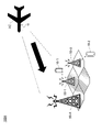
- FIG. 5 is a configuration diagram showing a wireless communication system 100A in a specific example of one embodiment.
- FIG. 6 is a configuration diagram showing a wireless communication system 100A in a specific example of one embodiment. Note that in FIGS. 5 and 6, drawing of the core network device 90 included in the wireless communication system 100 is omitted.
- the wireless communication system 100A includes an ATG base station device 50-A and two mobile base station devices 50-1, 50-2.
- the mobile base station device 50-1 and the mobile base station device 50-2 are installed on the ground and form a part of the ground network (TN: Terrestrial Networks).
- the mobile base station device 50-1 and the mobile base station device 50-2 each form a cell having a coverage area having a radius of several hundred meters to a dozen kilometers, for example.
- the mobile base station device 50-1 performs wireless communication with the terminal device 10-1 existing in the cell formed by itself, and provides the mobile communication service to the terminal device 10-1.
- the mobile base station device 50-2 performs wireless communication with the terminal device 10-2 existing in the cell formed by itself, and provides the mobile communication service to the terminal device 10-2.
- the ATG base station device 50-A is installed on the ground in the same manner as the mobile base station device 50-1 and the mobile base station device 50-2, and constitutes a part of the ATG (Air to Ground) network. do.
- the ATG base station apparatus 50-A forms a cell having a coverage area with a radius of tens to hundreds of kilometers, for example.
- the ATG base station device 50-A performs wireless communication with the communication device 11 instead of the terminal devices 10-1 and 10-2.
- the communication device 11 is provided on an object (hereinafter referred to as "flying object") flying over an aircraft AC or the like.
- the communication device 11 performs wireless communication with the ATG base station device 50-A, and also has a function as an access point of, for example, a wireless LAN (Local Area Network).
- the communication device 11 is, for example, a relay device for connecting a terminal device owned by an aircraft AC passenger to the ATG base station device 50-A via a wireless LAN.
- the communication device 11 complies with wireless LAN standards such as IEEE802.11b, IEEE802.11a, IEEE802.11g, IEEE802.11n, IEEE802.11ac, and IEEE802.11ax, and supports the 2.4GHz band and / or the 5GHz band. is doing. Since the hardware configuration of the communication device 11 is substantially the same as the hardware configuration of the terminal device 10 described above, the illustration and description thereof will be omitted.
- the mobile base station device 50-1, the mobile base station device 50-2, and the ATG base station device 50-A installed on the ground are not limited to the case where they are installed directly on the ground surface.
- the mobile base station device 50-1, the mobile base station device 50-2, and the ATG base station device 50-A may be installed in, for example, a building on the ground such as a building, a steel tower, or a utility pole. It may be installed on the mountainside, ridge, mountaintop, etc.
- the projectile provided with the communication device 11 is not limited to the case of an aircraft AC such as an airplane, a balloon, an airship, a helicopter, or a glider.
- the projectile may be, for example, a missile, a rocket, a space shuttle, a spacecraft, an artificial satellite, or the like.
- the ATG base station device 50-A employs beamforming in order to secure a wireless communication possible distance and area between the ATG base station device 50-A and the communication device 11.
- Beamforming is a technique for forming a directional pattern or a directional beam by controlling the amplitude and phase of each of a plurality of antennas to increase or decrease the gain of the antenna in a specific direction. By applying beamforming, it is possible to concentrate the signal strength of the transmission signal (transmission beam) in a specific direction and extend the communication distance.
- the ATG base station apparatus 50-A may support beam sweeping in which the directions of transmission signals are sequentially switched and a plurality of transmission signals (transmission beams) are transmitted.
- the ATG base station device 50-A when performing downlink radio communication from the ATG base station device 50-A to the communication device 11 provided in the aircraft AC, the ATG base station device 50-A directs the antenna 27 upward. At the same time, the directivity is controlled by using beamforming, and the radio wave of the transmission signal (transmission beam) is radiated toward the aircraft AC. Therefore, there is a possibility that the radio wave of the downlink wireless communication affects the wireless signal between the mobile base station devices 50-1 and 50-2 and the terminal devices 10-1 and 10-2 constituting the terrestrial network. It can be said that it is low.
- the communication device 11 when performing uplink wireless communication from the communication device 11 to the ATG base station device 50-A, the communication device 11 adopts beamforming and controls the directivity to control the transmission signal (transmission signal). Even if the radio wave of the transmission beam) is radiated toward the ATG base station apparatus 50-A, it may affect at least one of the mobile base station apparatus 50-1 and the mobile base station apparatus 50-2. That is, the mobile base station apparatus 50-1 and the mobile base station apparatus 50-2 are respectively arranged around the ATG base station apparatus 50-A and are the same as the ATG base station apparatus 50-A. Wireless communication is performed with the terminal device 10-1 or the terminal device 10-2 using the frequency band.
- the radio wave of the uplink wireless communication in the ATG network is the wireless communication between the mobile base station device 50-1 and the terminal device 10-1, or the mobile base station device 50-2 and the terminal device 10-2.
- the wireless communication between the mobile base station device 50-1 and the terminal device 10-1 and the mobile base station device 50- There is a demand for suppressing interference with at least one of the wireless communication between 2 and the terminal device 10-2.
- FIG. 7 is a configuration diagram showing an example of a functional block configuration of the ATG base station apparatus 50-A in one embodiment.
- FIG. 8 is a configuration diagram showing an example of a functional block configuration of the mobile base station apparatus 50-1 in one embodiment. 7 and 8 are for showing the functional blocks required in the present embodiment, and at least one of the ATG base station apparatus 50-A and the mobile base station apparatus 50-1 has a function other than those shown in the drawings. It does not preclude having a block.
- the functional block configuration of the mobile base station apparatus 50-2 is the same as or substantially the same as the functional block configuration of the mobile base station apparatus 50-1, the illustration and description thereof will be omitted.
- the ATG base station apparatus 50-A includes a transmission unit 51, a selection unit 52, and an acquisition unit 53 as functional blocks.
- the transmission unit 51 is configured to transmit uplink information regarding uplink wireless communication from the communication device 11 to the ATG base station device 50-A to the mobile base station devices 50-1 and 50-2. ..
- the mobile base station apparatus 50-1 and the mobile base station apparatus 50-2 are respectively arranged around the ATG base station apparatus 50-A and have the same frequency as the ATG base station apparatus 50-A. It is a terrestrial base station device that wirelessly communicates with the terminal device 10 using a band.
- the number of mobile base station devices 50-1 and 50-2 to which the transmission unit 51 transmits uplink information may be one or a plurality. Further, the transmission unit 51 may actively transmit the uplink information, or may passively transmit the uplink information in response to a trigger such as a request, an event, or the passage of time.
- the uplink information is arranged around the ATG base station device 50-A and has the same frequency as the ATG base station device 50-A. It is possible to notify the mobile base station devices 50-1 and 50-2, which perform wireless communication with the terminal devices 10-1 and 10-2 using the band, of the information of the uplink wireless communication that may interfere. .. Therefore, the mobile base station devices 50-1 and 50-2 use the notified uplink information to suppress interference, thereby interfering with the communication device 11 from the communication device 11 to the ATG base station device 50-A by wireless communication of the uplink. Can be easily and easily suppressed.
- the uplink information is, for example, the cell ID of the ATG base station device 50-A, the identification information of the communication device 11, for example, its own identifier (ID), SSID (Service Set Identifier) or ESS ID (Extended Service Set) of the access point. Identifier) or an identifier (ID) of the aircraft AC provided with the communication device 11.
- ID its own identifier
- SSID Service Set Identifier
- ESS ID Extended Service Set
- the uplink information may include the configuration information of the physical layer in NR or E-UTRA in place of the above-mentioned information or together with the above-mentioned information.
- the physical layer configuration information is specifically the number of slots allocated to the uplink and / or information about the uplink BWP, such as the bandwidth of the bandwidth portion, the frequency position in the overall bandwidth, and Information such as subcarrier intervals.
- the uplink information may include information about the uplink radio resource assigned to the communication device 11 in place of or together with the information described above.
- Information about uplink radio resources is specifically information about uplink scheduling, such as modulation scheme, power, estimated path loss, frequency position, time position, and the like.
- OFDM orthogonal frequency division multiplexing
- the frequency resource and the frequency resource for the uplink data channel are used in the scheduling in which the ATG base station apparatus 50-A allocates the radio resource to the communication apparatus 11.
- Time resources are allocated.
- the minimum allocation unit for radio resources is the resource block described above. That is, in NR, the minimum allocation unit of frequency resources is 12 subcarriers, and the minimum allocation unit of time resources is 14 OFDM symbols.
- the uplink information includes the information regarding the uplink radio resource assigned to the communication device 11, and as described later, for example, at least one of the time resource (time domain) and the frequency resource (frequency domain).
- the mobile base station apparatus 50-1 and 50-2 are subjected to wireless communication with the terminal apparatus 10-1 and 10-2 by using a resource block different from the uplink resource block of the communication apparatus 11. , Interference by wireless communication of the uplink from the communication device 11 to the ATG base station device 50-A can be easily avoided.
- the selection unit 52 has a plurality of mobile base station devices 50-1, 50-2 based on the respective distances between the ATG base station device 50-A and the mobile base station devices 50-1, 50-2. It is configured to select at least one of them.
- the selection unit 52 is, for example, between the distance between the ATG base station apparatus 50-A and the mobile base station apparatus 50-1 and the distance between the ATG base station apparatus 50-A and the mobile base station apparatus 50-2. You may compare with the distance and select the one with the shortest distance, or you may select all the ones with a distance less than a certain threshold.
- the distance between the ATG base station apparatus 50-A and each mobile base station apparatus 50-1, 50-2 information regarding the distance may be acquired from the above-mentioned core network apparatus 90, or each movement may be obtained.
- the distance may be measured by communicating with the body base station devices 50-1 and 50-2 and measuring the radio wave arrival time and the radio wave intensity.
- the transmission unit 51 may be configured to transmit the uplink information to the mobile base station devices 50-1 and 50-2 selected by the selection unit 52.
- the plurality of mobile base station apparatus 50-1, 50-2 By selecting at least one of them and transmitting the uplink information to the selected mobile base station devices 50-1 and 50-2, the target to be notified of the uplink information can be limited (restricted). can.
- the acquisition unit 53 is configured to acquire position information indicating the position of a flying object provided with a communication device 11 such as an aircraft AC. Since a flying object such as an aircraft AC usually moves at high speed in the air and changes its position significantly with the passage of time, it is preferable that the acquisition unit 53 acquires position information at predetermined time intervals.
- GNSS Global Navigation Satellite System
- the ATG base station apparatus 50-A includes a GPS receiver.
- the acquisition unit 53 uses, for example, OTDOA (Observed Time Difference Of Arrival), A-GPS (Assisted GPS), SUPL (Secure User Plane Location), etc. in place of GNSS or together with GNSS, and is used for aircraft AC and the like. You may acquire the position information of the flying object of.
- the selection unit 52 may be configured to select at least one of the plurality of mobile base station devices 50-1 and 50-2 using this position information. More specifically, the selection unit 52 is based on the respective distances between the ATG base station device 50-A and the mobile base station devices 50-1 and 50-2, and the position information acquired by the acquisition unit 53. Therefore, it is configured to select at least one of a plurality of mobile base station devices 50-1 and 50-2.
- a plurality of mobile bodies are based on the respective distances between the ATG base station device 50-A and the mobile base station devices 50-1 and 50-2, and the position information acquired by the acquisition unit 53.
- the base station devices 50-1 and 50-2 By selecting at least one of the base station devices 50-1 and 50-2, a mobile base station that is susceptible to interference due to uplink wireless communication depending on the position of a flying object such as an aircraft AC.
- the devices 50-1 and 50-2 can be selected, and the target for notifying the uplink information can be further limited (restricted).
- the mobile base station apparatus 50-1 includes a receiving unit 56 and an interference suppressing unit 57 as functional blocks.
- the receiving unit 56 is configured to receive the uplink information transmitted from the ATG base station apparatus 50-A.
- the receiving unit 56 may receive information other than the uplink information together with the uplink information or before or after receiving the uplink information.
- the mobile base station apparatus 50-1 may request the uplink information from the ATG base station apparatus 50-A, and the receiving unit 56 may receive the uplink information as an ACK signal thereof.
- the interference suppression unit 57 is configured to suppress interference due to uplink wireless communication from the communication device 11 to the ATG base station device 50-A based on the uplink information received from the ATG base station device 50-A. Has been done.
- the interference suppression unit 57 may adopt various methods in order to suppress interference due to uplink wireless communication based on uplink information.
- an interference canceller technique that generates an interference signal and removes (cancels) it from the received signal is adopted. Specifically, first, the interference suppression unit 57 generates an interference signal based on the uplink information. This interference signal is obtained by estimating the interference amount of the uplink transmission signal from the communication device 11 based on the uplink information from the received signal that is being interfered by the uplink wireless communication. Next, the interference suppression unit 57 generates a transmission signal from the terminal device 10-1 by subtracting the estimated interference signal from the entire received signal. In this way, the uplink transmission signal that causes interference is removed in the mobile base station apparatus 50-1.
- a replica (replication) of the interference signal is generated and superimposed on the received signal and the transmitted signal to remove the interference signal ().
- Interference canceller technology is adopted. Specifically, first, the interference suppression unit 57 generates a replica of the interference signal based on the uplink information. This interference signal replica is a signal such that the interference signal is canceled (cancelled). Next, the interference suppression unit 57 generates a transmission signal from the terminal device 10-1 by superimposing the generated interference signal replica on the entire received signal. In this way, the uplink transmission signal from the communication device 11 that causes interference is removed in the mobile base station device 50-1.
- an inter-cell interference control (ICIC: Inter-Cell Interference Coordination) technology that controls interference between cells is adopted in place of the above-mentioned interference canceller technology or in addition to the above-mentioned interference canceller technology.
- the interference suppression unit 57 is assigned to the communication device 11 based on the uplink information in the scheduling of the terminal device 10. Radio resources other than the uplink resource block are allocated to the terminal device 10-1. More specifically, the interference suppression unit 57 sets a resource block different from the uplink resource block of the communication device 11 in at least one of the time resource (time domain) and the frequency resource (frequency domain) in the terminal device 10-1. Assign to.
- the radio resources allocated to the terminal device 10-1 by the interference suppression unit 57 are a downlink from the mobile base station device 50-1 to the terminal device 10 and an uplink from the terminal device 10 to the mobile base station device 50-1. In both cases, it is preferable that the wireless resource is different from the uplink radio resource of the communication device 11. This makes it possible to avoid interference due to uplink wireless communication from the communication device 11.
- FIG. 9 is a time chart for explaining an example of the processing procedure performed by the wireless communication system 100A in one embodiment.
- FIG. 9 an example of transmitting uplink information to both the mobile base station device 50-1 and the mobile base station device 50-2 will be described.
- the communication device 11 transmits a scheduling request (SR: Scheduling Request) to the ATG base station device 50-A.
- SR scheduling request
- the ATG base station apparatus 50-A that has received the scheduling request (SR) performs scheduling to allocate the uplink data channel, that is, the uplink data transmission resource (radio resource) (as shown in FIG. 9). S101).
- DCI downlink control information
- the time resource (time) of the physical uplink shared channel (PUSCH) is determined by the time resource allocation field included in the downlink control information (DCI). Area) can be allocated.
- the ATG base station apparatus 50-A transmits the information of the wireless resource of the uplink data assigned in the scheduling in step S101 to the communication apparatus 11 (S102).
- the information of the radio resource of the uplink data is transmitted by the physical downlink control channel (PDCCH).
- the information of the radio resource of the uplink data includes the uplink grant (UL grant), and the uplink grant includes the control information regarding the physical uplink shared channel (PUSCH) assigned to the communication device 11.
- This control information includes the position of the allocated frequency resource, the position of the time resource, the modulation method, and the like.
- the physical downlink control channel (PDCCH) includes information on the identifier (ID) of the destination communication device 11, and the communication device 11 wirelessly depends on the presence or absence of information on its own identifier (ID). Determine if a resource is allocated.
- the transmission unit 51 of the ATG base station device 50-A transmits uplink information to the mobile base station device 50-1 and the mobile base station device 50-2, respectively (S103).
- the uplink information is, for example, information regarding the uplink radio resource notified to the communication device 11 in step S102.
- Each of the receiving units 56 of the mobile base station device 50-1 and the mobile base station device 50-2 receives the uplink information transmitted by the transmitting unit 51.
- the uplink information is transmitted to the mobile base station device 50-1 and the mobile base station device 50-2.
- the timing of transmitting the uplink information to the mobile base station apparatus 50-1 and the mobile base station apparatus 50-2 may be after allocating the wireless resource of the uplink data in step S101, and before step S102 or. It may be simultaneous with step S102.
- the transmission unit 51 transmits the uplink information to the mobile base station apparatus 50-1 and the mobile base station apparatus 50-2 when the uplink radio resource is allocated.
- the mobile base station device 50-1 and the mobile base are used before the uplink wireless communication from the communication device 11 to the ATG base station device 50-A is performed, specifically, before the uplink data is transmitted. Uplink information can be notified to the station device 50-2.
- the communication device 11 uses the uplink data radio resource allocated in the scheduling of step S101, and transfers the uplink data to the ATG base station device 50-. It is transmitted to A (S104).
- the interference suppression units 57 of the mobile base station devices 50-1 and 50-2 respectively use the uplink radio from the communication device 11 to the ATG base station device 50-A based on the received uplink information. Suppresses interference due to communication (S105).
- the ATG base station apparatus 50-A transmits uplink information regarding the uplink wireless communication from the communication apparatus 11 to the ATG base station apparatus 50-A to the mobile base station apparatus 50-1, 50-2.
- the mobile base station devices 50-1 and 50-2 suppress the interference due to the wireless communication of the uplink from the communication device 11 to the ATG base station device 50-A based on the uplink information, thereby suppressing the ATG.
- the ATG network including the base station apparatus 50-A and the terrestrial network including the mobile base station apparatus 50-1, 50-2 can coexist while using the same frequency band.
- FIG. 10 is a flowchart for explaining an example of a processing procedure performed by the ATG base station apparatus 50-A in one embodiment.
- FIG. 11 is a flowchart for explaining an example of a processing procedure performed by the mobile base station apparatus 50-1 in one embodiment. Since the processing procedure of the mobile base station apparatus 50-2 is the same as or substantially the same as the processing procedure of the mobile base station apparatus 50-1, the illustration and description thereof will be omitted.
- the acquisition unit 53 acquires position information indicating the position of a flying object provided with a communication device 11 such as an aircraft AC (S201).
- a plurality of selection units 52 are used based on the respective distances between the ATG base station devices 50-A and the mobile base station devices 50-1 and 50-2, and the position information acquired in step S201. At least one of the mobile base station devices 50-1 and 50-2 of the above is selected (S202). For example, when the position information could not be acquired in step S201, the selection unit 52 determines based on the respective distances between the ATG base station apparatus 50-A and the mobile base station apparatus 50-1, 50-2. At least one of a plurality of mobile base station devices 50-1, 50-2 may be selected. Hereinafter, the selection unit 52 will be described as assuming that the mobile base station apparatus 50-1 is selected.
- the transmission unit 51 transmits the uplink information to the mobile base station apparatus 50-1 selected in step S202 (S203).
- step S203 since the flying object provided with the communication device 11 changes its position from moment to moment, it is preferable to repeat steps S201 to S203 again after a predetermined time has elapsed after step S203.
- the receiving unit 56 determines whether or not the uplink information has been received from the ATG base station apparatus 50-A (S221).
- step S221 if the uplink information is not received from the ATG base station apparatus 50-A, the determination in step S221 is repeated until the uplink information from the ATG base station apparatus 50-A is received.
- the interference suppression unit 57 receives the uplink information from the communication apparatus 11 to the ATG base station apparatus 50. -Suppresses interference due to wireless communication of the uplink to A (S222).
- uplink information is transmitted to the mobile base station apparatus 50-1, 50-2.
- the mobile base station device is arranged around the ATG base station device 50-A and wirelessly communicates with the terminal devices 10-1 and 10-2 using the same frequency band as the ATG base station device 50-A.
- Information on uplink wireless communication that may interfere can be notified to 50-1 and 50-2. Therefore, the mobile base station devices 50-1 and 50-2 use the notified uplink information to suppress interference, thereby interfering with the communication device 11 from the communication device 11 to the ATG base station device 50-A by wireless communication of the uplink. Can be easily and easily suppressed.
- the ATG base station apparatus 50-A provides uplink information regarding uplink wireless communication from the communication apparatus 11 to the ATG base station apparatus 50-A as a mobile base station.
- the mobile base station device 50-1 and 50-2 transmit to the devices 50-1 and 50-2, and the mobile base station device 50-1 and 50-2 transmit the uplink radio from the communication device 11 to the ATG base station device 50-A based on the uplink information. Suppress interference due to communication.
- the ATG network including the ATG base station apparatus 50-A and the terrestrial network including the mobile base station apparatus 50-1 and 50-2 can coexist while using the same frequency band.
Landscapes
- Engineering & Computer Science (AREA)
- Computer Networks & Wireless Communication (AREA)
- Signal Processing (AREA)
- Mobile Radio Communication Systems (AREA)
Abstract
L'invention concerne un dispositif de station de base, un système de communication sans fil et un procédé de communication sans fil permettant de supprimer une interférence d'une communication sans fil de liaison montante. La présente invention concerne un dispositif de station de base ATG 50-a installé sur le sol qui communique sans fil avec un dispositif de communication (11) prévu sur un AC d'aéronef, ledit dispositif de station de base comprenant une unité de transmission (51) au moyen duquel des informations de liaison montante relatives à une communication sans fil de liaison montante, depuis le dispositif de communication (11) vers le dispositif de station de base ATG 50-A, sont transmises à des dispositifs de station de base d'unité mobile (50-1, 50-2) disposés à la périphérie du dispositif de station de base ATG 50Aa, ladite unité de transmission (51) communiquant sans fil avec des dispositifs terminaux (10-1, 10-2) en utilisant la même bande de fréquences que le dispositif de station de base ATG 50-A.
Priority Applications (1)
| Application Number | Priority Date | Filing Date | Title |
|---|---|---|---|
| PCT/JP2020/036539 WO2022064672A1 (fr) | 2020-09-28 | 2020-09-28 | Dispositif de station de base, système de communication sans fil et procédé de communication sans fil |
Applications Claiming Priority (1)
| Application Number | Priority Date | Filing Date | Title |
|---|---|---|---|
| PCT/JP2020/036539 WO2022064672A1 (fr) | 2020-09-28 | 2020-09-28 | Dispositif de station de base, système de communication sans fil et procédé de communication sans fil |
Publications (1)
| Publication Number | Publication Date |
|---|---|
| WO2022064672A1 true WO2022064672A1 (fr) | 2022-03-31 |
Family
ID=80846312
Family Applications (1)
| Application Number | Title | Priority Date | Filing Date |
|---|---|---|---|
| PCT/JP2020/036539 Ceased WO2022064672A1 (fr) | 2020-09-28 | 2020-09-28 | Dispositif de station de base, système de communication sans fil et procédé de communication sans fil |
Country Status (1)
| Country | Link |
|---|---|
| WO (1) | WO2022064672A1 (fr) |
Cited By (4)
| Publication number | Priority date | Publication date | Assignee | Title |
|---|---|---|---|---|
| CN115086969A (zh) * | 2022-06-24 | 2022-09-20 | 中国电信股份有限公司 | 干扰协调方法及装置、电子设备、计算机可读介质 |
| CN116582165A (zh) * | 2023-07-07 | 2023-08-11 | 中国电信股份有限公司 | 通信方法、系统、装置、设备及存储介质 |
| WO2023240968A1 (fr) * | 2022-06-14 | 2023-12-21 | 中国电信股份有限公司 | Système, procédé et appareil communication mobile aéronautique, dispositif électronique et support de stockage |
| JP7466072B1 (ja) | 2024-01-23 | 2024-04-11 | ソフトバンク株式会社 | 移動通信システム |
Citations (1)
| Publication number | Priority date | Publication date | Assignee | Title |
|---|---|---|---|---|
| WO2011099511A1 (fr) * | 2010-02-12 | 2011-08-18 | 三菱電機株式会社 | Système de communication mobile |
-
2020
- 2020-09-28 WO PCT/JP2020/036539 patent/WO2022064672A1/fr not_active Ceased
Patent Citations (1)
| Publication number | Priority date | Publication date | Assignee | Title |
|---|---|---|---|---|
| WO2011099511A1 (fr) * | 2010-02-12 | 2011-08-18 | 三菱電機株式会社 | Système de communication mobile |
Non-Patent Citations (1)
| Title |
|---|
| ZTE CORPORATION: "Discussion on ATG network", 3GPP DRAFT; RP-201053, 3RD GENERATION PARTNERSHIP PROJECT (3GPP), MOBILE COMPETENCE CENTRE ; 650, ROUTE DES LUCIOLES ; F-06921 SOPHIA-ANTIPOLIS CEDEX ; FRANCE, vol. RAN WG4, no. E-meeting; 20200629 - 20200703, 22 June 2020 (2020-06-22), Mobile Competence Centre ; 650, route des Lucioles ; F-06921 Sophia-Antipolis Cedex ; France , XP051903711 * |
Cited By (10)
| Publication number | Priority date | Publication date | Assignee | Title |
|---|---|---|---|---|
| WO2023240968A1 (fr) * | 2022-06-14 | 2023-12-21 | 中国电信股份有限公司 | Système, procédé et appareil communication mobile aéronautique, dispositif électronique et support de stockage |
| JP2025519563A (ja) * | 2022-06-14 | 2025-06-26 | チャイナ・テレコム・コーポレーション・リミテッド | 航空移動通信システム、方法、装置、電子機器及び記憶媒体 |
| JP7781316B2 (ja) | 2022-06-14 | 2025-12-05 | チャイナ・テレコム・コーポレーション・リミテッド | 航空移動通信システム、方法、装置、電子機器及び記憶媒体 |
| CN115086969A (zh) * | 2022-06-24 | 2022-09-20 | 中国电信股份有限公司 | 干扰协调方法及装置、电子设备、计算机可读介质 |
| CN115086969B (zh) * | 2022-06-24 | 2023-10-31 | 中国电信股份有限公司 | 干扰协调方法及装置、电子设备、计算机可读介质 |
| CN116582165A (zh) * | 2023-07-07 | 2023-08-11 | 中国电信股份有限公司 | 通信方法、系统、装置、设备及存储介质 |
| CN116582165B (zh) * | 2023-07-07 | 2023-10-03 | 中国电信股份有限公司 | 通信方法、系统、装置、设备及存储介质 |
| JP7466072B1 (ja) | 2024-01-23 | 2024-04-11 | ソフトバンク株式会社 | 移動通信システム |
| WO2025158702A1 (fr) * | 2024-01-23 | 2025-07-31 | ソフトバンク株式会社 | Système de communication mobile |
| JP2025113782A (ja) * | 2024-01-23 | 2025-08-04 | ソフトバンク株式会社 | 移動通信システム |
Similar Documents
| Publication | Publication Date | Title |
|---|---|---|
| CN115004579B (zh) | 用于非地面网络的卫星信息的通信 | |
| CN112970315B (zh) | 用于无线通信的方法、装置和非暂时性计算机可读介质 | |
| CN110999373B (zh) | 无线通信系统中的装置和方法、计算机可读存储介质 | |
| CN117200860A (zh) | 用于移动网络中的无线电资源管理的方法 | |
| JP7725584B2 (ja) | 測位用の直交ランダムアクセスチャネル(rach)プリアンブルシーケンス | |
| EP3667643A1 (fr) | Appareil et procédé de système de communication sans fil, et support d'informations lisible par ordinateur | |
| WO2022064672A1 (fr) | Dispositif de station de base, système de communication sans fil et procédé de communication sans fil | |
| EP3965461A1 (fr) | Appareil et procédé dans un système de communication sans fil et support d'informations lisible par ordinateur pour allocationde ressources en fonction de la hauteur | |
| CN116349327A (zh) | 用于空闲或非活动状态ue的寻呼指示 | |
| JP2021503217A (ja) | Nrアップリンク(ul)キャリアである第1のulキャリアと補助アップリンク(sul)キャリアである第2のulキャリアとを含むnrセルであるターゲットセルへのハンドオーバ | |
| KR20150113960A (ko) | 무선 통신 방법, 기지국 및 무선 통신 디바이스 | |
| WO2019044635A1 (fr) | Dispositif de communication | |
| CN117941309A (zh) | 与用于执行无测量间隙的处理的定位参考信号(prs)有关的条件 | |
| CN117837232A (zh) | 无线电资源控制(rrc)空闲或非活动状态定位期间的辅助数据更新过程 | |
| JP2024529036A (ja) | 非アクティブ状態において測位するための帯域幅部分(bwp)構成 | |
| WO2021033282A1 (fr) | Dispositif terminal, dispositif de station de base, et procédé de communication sans fil | |
| CN114208326B (zh) | 基于分组的prs资源映射和配置 | |
| US20250056471A1 (en) | Mixed ntn and tn positioning configurations for nr positioning and related ue capabilities | |
| WO2021156994A1 (fr) | Dispositif terminal, dispositif de station de base, et procédé de communication sans fil | |
| JP7394856B2 (ja) | 端末装置、基地局装置、及び無線通信方法 | |
| JP7574502B2 (ja) | 端末装置、基地局装置、及び無線通信方法 | |
| TWI915425B (zh) | 用於定位的正交隨機存取信道前置碼序列 | |
| JP7621389B2 (ja) | 端末装置及び無線通信方法 | |
| EP4576867A1 (fr) | Dispositif terminal et procédé de communication sans fil | |
| US20250227649A1 (en) | Ue implementation for prs resource set and trps prioritizations |
Legal Events
| Date | Code | Title | Description |
|---|---|---|---|
| 121 | Ep: the epo has been informed by wipo that ep was designated in this application |
Ref document number: 20955266 Country of ref document: EP Kind code of ref document: A1 |
|
| NENP | Non-entry into the national phase |
Ref country code: DE |
|
| 122 | Ep: pct application non-entry in european phase |
Ref document number: 20955266 Country of ref document: EP Kind code of ref document: A1 |
|
| NENP | Non-entry into the national phase |
Ref country code: JP |