WO2022070302A1 - 自走装置 - Google Patents
自走装置 Download PDFInfo
- Publication number
- WO2022070302A1 WO2022070302A1 PCT/JP2020/037136 JP2020037136W WO2022070302A1 WO 2022070302 A1 WO2022070302 A1 WO 2022070302A1 JP 2020037136 W JP2020037136 W JP 2020037136W WO 2022070302 A1 WO2022070302 A1 WO 2022070302A1
- Authority
- WO
- WIPO (PCT)
- Prior art keywords
- self
- laser sensor
- propelled device
- laser
- traveling body
- Prior art date
- Legal status (The legal status is an assumption and is not a legal conclusion. Google has not performed a legal analysis and makes no representation as to the accuracy of the status listed.)
- Ceased
Links
Images


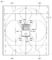


Classifications
-
- G—PHYSICS
- G05—CONTROLLING; REGULATING
- G05D—SYSTEMS FOR CONTROLLING OR REGULATING NON-ELECTRIC VARIABLES
- G05D1/00—Control of position, course, altitude or attitude of land, water, air or space vehicles, e.g. using automatic pilots
- G05D1/02—Control of position or course in two dimensions
- G05D1/021—Control of position or course in two dimensions specially adapted to land vehicles
- G05D1/0231—Control of position or course in two dimensions specially adapted to land vehicles using optical position detecting means
- G05D1/0238—Control of position or course in two dimensions specially adapted to land vehicles using optical position detecting means using obstacle or wall sensors
- G05D1/024—Control of position or course in two dimensions specially adapted to land vehicles using optical position detecting means using obstacle or wall sensors in combination with a laser
-
- B—PERFORMING OPERATIONS; TRANSPORTING
- B25—HAND TOOLS; PORTABLE POWER-DRIVEN TOOLS; MANIPULATORS
- B25J—MANIPULATORS; CHAMBERS PROVIDED WITH MANIPULATION DEVICES
- B25J5/00—Manipulators mounted on wheels or on carriages
- B25J5/007—Manipulators mounted on wheels or on carriages mounted on wheels
-
- G—PHYSICS
- G01—MEASURING; TESTING
- G01S—RADIO DIRECTION-FINDING; RADIO NAVIGATION; DETERMINING DISTANCE OR VELOCITY BY USE OF RADIO WAVES; LOCATING OR PRESENCE-DETECTING BY USE OF THE REFLECTION OR RERADIATION OF RADIO WAVES; ANALOGOUS ARRANGEMENTS USING OTHER WAVES
- G01S7/00—Details of systems according to groups G01S13/00, G01S15/00, G01S17/00
- G01S7/48—Details of systems according to groups G01S13/00, G01S15/00, G01S17/00 of systems according to group G01S17/00
- G01S7/481—Constructional features, e.g. arrangements of optical elements
- G01S7/4814—Constructional features, e.g. arrangements of optical elements of transmitters alone
-
- G—PHYSICS
- G01—MEASURING; TESTING
- G01S—RADIO DIRECTION-FINDING; RADIO NAVIGATION; DETERMINING DISTANCE OR VELOCITY BY USE OF RADIO WAVES; LOCATING OR PRESENCE-DETECTING BY USE OF THE REFLECTION OR RERADIATION OF RADIO WAVES; ANALOGOUS ARRANGEMENTS USING OTHER WAVES
- G01S17/00—Systems using the reflection or reradiation of electromagnetic waves other than radio waves, e.g. lidar systems
- G01S17/02—Systems using the reflection of electromagnetic waves other than radio waves
- G01S17/06—Systems determining position data of a target
- G01S17/42—Simultaneous measurement of distance and other co-ordinates
-
- G—PHYSICS
- G01—MEASURING; TESTING
- G01S—RADIO DIRECTION-FINDING; RADIO NAVIGATION; DETERMINING DISTANCE OR VELOCITY BY USE OF RADIO WAVES; LOCATING OR PRESENCE-DETECTING BY USE OF THE REFLECTION OR RERADIATION OF RADIO WAVES; ANALOGOUS ARRANGEMENTS USING OTHER WAVES
- G01S17/00—Systems using the reflection or reradiation of electromagnetic waves other than radio waves, e.g. lidar systems
- G01S17/88—Lidar systems specially adapted for specific applications
- G01S17/89—Lidar systems specially adapted for specific applications for mapping or imaging
-
- G—PHYSICS
- G01—MEASURING; TESTING
- G01S—RADIO DIRECTION-FINDING; RADIO NAVIGATION; DETERMINING DISTANCE OR VELOCITY BY USE OF RADIO WAVES; LOCATING OR PRESENCE-DETECTING BY USE OF THE REFLECTION OR RERADIATION OF RADIO WAVES; ANALOGOUS ARRANGEMENTS USING OTHER WAVES
- G01S17/00—Systems using the reflection or reradiation of electromagnetic waves other than radio waves, e.g. lidar systems
- G01S17/88—Lidar systems specially adapted for specific applications
- G01S17/93—Lidar systems specially adapted for specific applications for anti-collision purposes
- G01S17/931—Lidar systems specially adapted for specific applications for anti-collision purposes of land vehicles
-
- G—PHYSICS
- G01—MEASURING; TESTING
- G01S—RADIO DIRECTION-FINDING; RADIO NAVIGATION; DETERMINING DISTANCE OR VELOCITY BY USE OF RADIO WAVES; LOCATING OR PRESENCE-DETECTING BY USE OF THE REFLECTION OR RERADIATION OF RADIO WAVES; ANALOGOUS ARRANGEMENTS USING OTHER WAVES
- G01S7/00—Details of systems according to groups G01S13/00, G01S15/00, G01S17/00
- G01S7/48—Details of systems according to groups G01S13/00, G01S15/00, G01S17/00 of systems according to group G01S17/00
- G01S7/481—Constructional features, e.g. arrangements of optical elements
- G01S7/4817—Constructional features, e.g. arrangements of optical elements relating to scanning
Definitions
- This disclosure relates to a wheel-driven self-propelled device.
- Unmanned production systems such as factories are desired.
- Self-propelled devices are being developed to achieve unmanned operation.
- the self-propelled device transports the workpieces and tools before machining to each machine tool, and collects the workpieces and used tools that have been machined by each machine tool.
- Patent Document 1 discloses a self-propelled device for the purpose of "creating map information well".
- the self-propelled device is a distance measuring device that rotationally drives a light projecting unit that emits projected light and outputs distance measurement data based on the light received by the reflected light reflected by the object to be measured, and a distance measuring device based on the distance measurement data. It is equipped with a map creation unit that creates map information and an obstacle sensor that detects obstacles.
- the self-propelled device disclosed in Patent Document 1 detects an obstacle based on the projected light emitted in the horizontal direction. Therefore, the self-propelled device can detect an obstacle existing in the traveling direction of the mobile device, but cannot detect an obstacle existing above or below the self-propelled device. Therefore, a self-propelled device capable of detecting an obstacle above or below the self-propelled device is desired.
- the self-propelled device includes a wheel-driven traveling body and a laser sensor.
- the laser sensor irradiates the laser light while rotating it around the laser sensor, and receives the reflected light of the laser light to measure the distance to an object around the laser sensor with the laser sensor as the center. It is configured to output two-dimensional distance data represented by each angle.
- the self-propelled device includes a control device for controlling the traveling of the traveling body based on the two-dimensional distance data output from the laser sensor.
- the laser sensor is provided on the traveling body so that the scanning surface, which is a range through which the laser beam passes during rotation of the laser beam, has a predetermined angle with respect to the horizontal plane.
- the self-propelled device further includes an arm robot provided on the traveling body.
- the laser sensor is provided on the traveling body so that the scanning surface includes the movable range of the arm robot.
- the self-propelled device further comprises a cover for accommodating the laser sensor.
- the laser sensor or the cover is provided on the traveling body so that the incident angle of the laser beam with respect to the cover is larger than 0 degrees and smaller than 90 degrees.
- the longer the distance between the laser sensor and the cover of the laser sensor or the cover the smaller the minimum incident angle of the laser light incident on the cover during the rotation of the laser light. As described above, it is provided on the traveling body.
- control device sequentially acquires the two-dimensional distance data from the laser sensor while rotating the traveling body about the rotation axis in the vertical direction, and the two-dimensional obtained sequentially. Based on the distance data, a process of generating three-dimensional data representing the space around the traveling main body is executed.
- the process of generating the three-dimensional data is executed based on the fact that the self-propelled device is included in a preset range.
- the self-propelled device is configured to be able to communicate with a user terminal for operating the self-propelled device.
- the process of generating the three-dimensional data is executed based on receiving an execution command based on the execution operation of the process from the user terminal.
- the traveling body has three or more drive wheels.
- FIG. 1 is a diagram showing the appearance of the self-propelled device 100.
- the self-propelled device 100 transports an object to be transported such as a work or a tool to an arbitrary place.
- the self-propelled device 100 includes a traveling main body 10 and an arm robot 20.
- the traveling body 10 has a cover 110.
- a laser sensor 105 (see FIG. 2), which will be described later, is provided inside the cover 110.
- the self-propelled device 100 controls the traveling of the traveling main body 10 based on the detection result of the laser sensor 105.
- the traveling body 10 has a driving wheel WA and a non-driving wheel WB.
- the drive wheel WA and the non-drive wheel WB are, for example, omni wheels.
- the drive wheel WA is a wheel that is rotationally driven by receiving the driving force of a motor M (see FIG. 6) described later.
- the non-driving wheel WB is a wheel that follows the driving wheel WA without directly receiving the driving force of the motor.
- FIG. 1 shows a traveling body 10 having two drive wheels WA, but the number of drive wheels WA is arbitrary. Typically, the traveling body 10 has two or more drive wheels WA.
- FIG. 1 shows a traveling body 10 having two non-driving wheel WBs, but the number of non-driving wheel WBs is arbitrary. Typically, the traveling body 10 has one or more non-driving wheels WB.
- FIG. 1 shows an example in which the drive wheel WA is a front wheel and the non-drive wheel WB is a rear wheel, but the drive wheel WA is a rear wheel and the non-drive wheel WB is a front wheel. May be good.
- the traveling body 10 is provided with two drive wheels WA.
- the first and second drive wheels WA are responsible for traveling in the forward direction R and the reverse direction B.
- the traveling body 10 is provided with three or more drive wheel WAs.
- the first and second drive wheels WA are responsible for traveling in the forward direction R and the reverse direction B
- the third drive wheel WA is responsible for traveling in the orthogonal direction of the forward direction R.
- the third drive wheel WA is provided at the lower part of the traveling body 10 at a place separated by a predetermined distance in the forward direction R or the reverse direction B from the position of the center of gravity of the traveling body 10.
- the self-propelled device 100 can rotate the traveling body 10 with the rotation center in the vertical direction passing through the position of the center of gravity of the traveling body 10.
- the arm robot 20 is provided on the traveling body 10. Further, a place for the work W is provided on the traveling main body 10. The arm robot 20 grips the work W and moves the work W to a designated place.
- the device may be installed on the traveling body 10.
- the transfer device may be a robot (for example, an autoloader) driven by 2 to 3 axes.
- FIG. 2 is a diagram showing a laser sensor 105 and two-dimensional distance data D output from the laser sensor 105.
- the laser sensor 105 is configured to irradiate while rotating the laser light LA with the central axis AX of the laser sensor 105 as the center of rotation, and to receive the reflected light of the laser light LA. As a result, the laser sensor 105 outputs the two-dimensional distance data D in which the distance to the surrounding object is represented by the angle with respect to the central axis AX.
- the two-dimensional distance data D represents the distance to each object existing in the scanning surface SC for each irradiation angle.
- the laser sensor 105 is composed of an irradiation unit, a mirror, and a light receiving unit.
- the irradiation unit irradiates the mirror with a laser beam.
- the mirror is made rotatable around the central axis AX by a motor (not shown), and reflects the laser beam LA in each direction.
- the laser sensor 105 irradiates the laser beam LA in each direction.
- the laser beam LA is reflected by the object and returns to the laser sensor 105.
- the laser sensor 105 receives the reflected light at the light receiving unit.
- the laser sensor 105 receives the reflected light from the object and calculates the distance to the object. As an example, the laser sensor 105 calculates the distance from the laser sensor 105 to an object based on the time from irradiating the laser beam LA to receiving the reflected light of the laser beam LA. Typically, the laser sensor 105 calculates the distance to an object by multiplying the speed of light by the time. The laser sensor 105 outputs two-dimensional distance data D representing the distance for each angle with respect to the central axis AX by associating the distance with the irradiation angle of the laser beam LA.
- the angle range of the distance data output by the laser sensor 105 is arbitrarily set. In the example of FIG. 2, the angle range of 0 degrees to 270 degrees is effectively set.
- FIG. 3 is a view showing the self-propelled device 100 from the side surface direction.
- FIG. 4 is a view showing the self-propelled device 100 from above.
- the laser sensor 105 is provided, for example, on the front surface of the traveling body 10.
- the front surface of the self-propelled device 100 is a surface of the surface constituting the traveling main body 10 that corresponds to the forward direction of the self-propelled device 100.
- the range of the effective angle for distance measurement is set to the range of 180 degrees on the forward direction side.
- the range of 180 degrees on the reverse direction side is set to invalid.
- the laser sensor 105 is provided on the traveling body 10 so that the scanning surface SC of the laser beam LA has a predetermined angle ⁇ with respect to the horizontal plane H (ground). That is, the laser sensor 105 is provided on the traveling body 10 so that the scanning surface SC is not parallel to the horizontal plane H.
- the angle ⁇ is greater than 0 degrees and greater than 90 degrees.
- the positive angle ⁇ represents an angle on the sky side of the horizontal plane H.
- the self-propelled device 100 can detect an obstacle existing above the traveling main body 10.
- the angle ⁇ is greater than 30 degrees and less than 60 degrees.
- FIG. 3 shows an example in which the angle ⁇ is about 45 degrees.
- the angle ⁇ is greater than -90 degrees and less than 0 degrees.
- the negative angle ⁇ represents an angle on the ground side of the horizontal plane H.
- the angle ⁇ is greater than -60 degrees and less than -30 degrees.
- the laser sensor 105 is provided on the traveling body 10 in a state of being tilted by a predetermined angle ⁇ with respect to the scanning surface SC, so that the self-propelled device 100 exists above the traveling body 10 or below the traveling body 10. It becomes possible to detect obstacles. Further, the self-propelled device 100 can three-dimensionally scan the surrounding shape by sequentially acquiring the two-dimensional distance data D from the laser sensor 105 while the self-propelled device 100 is self-propelled.
- the laser sensor 105 is provided on the traveling body 10 so that the scanning surface SC includes the movable range of the arm robot 20 (see FIG. 1). In other words, the scanning surface SC overlaps at least a part of the movable range of the arm robot 20. This makes it possible for the laser sensor 105 to capture the movement of the arm robot 20.
- FIG. 5 is a diagram showing an example of the arrangement relationship between the laser sensor 105 and the cover 110.
- the cover 110 is composed of, for example, a member that transmits the laser beam L1 emitted from the laser sensor 105.
- the cover 110 is a resin cover.
- the laser beam L1 shown in FIGS. 5 (A) and 5 (B) indicates a laser beam having the smallest incident angle ⁇ with respect to the cover 110 among the laser beams incident on the cover 110 during the rotation of the laser beam.
- the incident angle ⁇ indicates the angle formed by the laser beam L1 and the orthogonal direction of the cover surface.
- the cover surface indicates a surface on which the laser beam L1 is incident among the surfaces constituting the cover 110.
- FIG. 5A shows an example in which the laser beam L1 is incident on the cover 110 at a right angle.
- the incident angle ⁇ becomes 0 degrees
- a part of the laser beam L1 is reflected by the cover 110 and returns to the laser sensor 105 as the reflected light L2.
- the rest of the laser beam L1 is reflected by the object OB and returns to the laser sensor 105 as reflected light L3.
- the laser sensor 105 erroneously detects the cover 110 as an obstacle by the reflected light L2.
- FIG. 5B shows an example in which the laser beam L1 does not enter the cover 110 at a right angle.
- the incident angle ⁇ is larger than 0 degrees
- the reflected light L2 from the cover 110 does not return to the laser sensor 105.
- the reflected light L3 from the object OB returns to the laser sensor 105.
- the laser sensor 105 can detect the object OB without detecting the cover 110. Therefore, the laser sensor 105 or the cover 110 is provided on the traveling body 10 so that the laser beam L1 incident on the cover 110 during the rotation of the laser beam does not incident on the cover 110 at a right angle.
- the laser sensor 105 or the cover 110 is provided on the traveling body 10 so that the incident angle ⁇ is larger than 0 degrees and smaller than 90 degrees.
- the degree of inclination of the cover 110 with respect to the laser beam L1 is determined according to the distance d between the laser sensor 105 and the cover 110.
- the distance d represents the distance through which the laser beam L1 passes between the laser sensor 105 and the cover 110.
- the laser sensor 105 or the cover 110 is provided on the traveling main body 10 so that the incident angle ⁇ 1 becomes smaller as the distance d becomes longer.
- the laser sensor 105 or the cover 110 is provided on the traveling body 10 so that the incident angle ⁇ 1 becomes larger as the distance d is shorter.
- the self-propelled device 100 can more reliably prevent the cover 110 from being erroneously detected as an obstacle.
- FIG. 6 is a diagram showing an example of the hardware configuration of the self-propelled device 100.
- the self-propelled device 100 includes a control device 101, a ROM (Read Only Memory) 102, a RAM (Random Access Memory) 103, a communication interface 104, the above-mentioned laser sensor 105 (see FIG. 2), and a motor drive device 106. And the storage device 120. These components are connected to bus 109.
- the control device 101 is composed of, for example, at least one integrated circuit.
- the integrated circuit is, for example, at least one CPU (Central Processing Unit), at least one GPU (Graphics Processing Unit), at least one ASIC (Application Specific Integrated Circuit), at least one FPGA (Field Programmable Gate Array), or them. It may be composed of a combination of.
- the control device 101 controls the operation of the self-propelled device 100 by executing various programs such as the control program 122 and the operating system.
- the control device 101 reads the control program 122 from the storage device 120 or the ROM 102 into the RAM 103 based on the reception of the execution command of the control program 122.
- the RAM 103 functions as a working memory and temporarily stores various data necessary for executing the control program 122.
- a LAN Local Area Network
- an antenna or the like is connected to the communication interface 104.
- the self-propelled device 100 realizes wireless communication or wired communication with an external device via the communication interface 104.
- the external device includes, for example, a server (not shown), a user terminal for operating the self-propelled device 100 (not shown), and the like.
- the user terminal is, for example, a tablet terminal or a smartphone. The user can control the traveling of the self-propelled device 100 via the user terminal.
- the motor drive device 106 controls the rotation of the motor M according to a control command from the control device 101.
- the control command includes, for example, a forward rotation command of the motor M, a reverse rotation command of the motor M, a rotation speed of the motor M, and the like.
- the motor M for example, a stepping motor, a servo motor, or the like is adopted.
- the above-mentioned drive wheel WA (see FIG. 1) is connected to the motor M.
- the number of motors M is the same as the number of drive wheels WA.
- the storage device 120 is a storage medium such as a hard disk or a flash memory.
- the storage device 120 stores the control program 122, the three-dimensional map 124, and the like. The details of the three-dimensional map 124 will be described later.
- the storage location of the control program 122 and the three-dimensional map 124 is not limited to the storage device 120, but is stored in a storage area of the control device 101 (for example, a cache memory), a ROM 102, a RAM 103, an external device (for example, a server), or the like. May be.
- control program 122 may be provided by being incorporated into a part of an arbitrary program, not as a single program.
- the travel control process of the self-propelled device 100 by the control program 122 is realized in cooperation with an arbitrary program. Even a program that does not include such a part of the modules does not deviate from the purpose of the control program 122 according to the present embodiment.
- some or all of the functions provided by the control program 122 may be realized by dedicated hardware.
- the self-propelled device 100 may be configured in the form of a so-called cloud service in which at least one server executes a part of the processing of the control program 122.
- FIG. 7 is a diagram showing an example of the functional configuration of the self-propelled device 100.
- control device 101 of the self-propelled device 100 includes a map generation unit 152, a travel control unit 154, and a rotation scan unit 156 as an example of the functional configuration.
- map generation unit 152 maps a map to a map.
- the map generation unit 152 is a three-dimensional map 124 (three-dimensional data) representing the space around the self-propelled device 100 based on the two-dimensional distance data D sequentially acquired from the laser sensor 105 while the self-propelled device 100 is being driven. To generate.
- the three-dimensional map 124 is generated by, for example, SLAM (Simultaneous Localization and Mapping) technology.
- the three-dimensional map 124 is information generated for specifying the position of the self-propelled device 100, and is information indicating the position of a stationary object in the traveling place of the self-propelled device 100.
- the stationary object is, for example, a wall, a shelf, or the like.
- the three-dimensional map 124 is generated, for example, by the user manually operating the self-propelled device 100 using the user terminal.
- the operation signal corresponding to the user operation is transmitted to the control device 101 via the communication interface 104, so that the control device 101 outputs a command to the motor drive device 106 according to the operation signal and is a self-propelled device.
- Control 100 runs.
- the control device 101 sets the position of the object around the self-propelled device 100 on the three-dimensional map 124 based on the two-dimensional distance data D input from the laser sensor 105 and the position of the self-propelled device 100.
- Map The position of the self-propelled device 100 is specified, for example, based on the drive information of the motor drive device 106.
- information indicating the presence or absence of an object is associated with each of the three-dimensional coordinate values (x, y, z).
- the scanning surface SC (see FIG. 3) of the laser sensor 105 is parallel to the horizontal plane, the laser sensor 105 cannot acquire information on an object in the height direction and can only generate a two-dimensional map.
- the scanning surface SC (see FIG. 3) of the laser sensor 105 is tilted with respect to the horizontal plane. Therefore, the self-propelled device 100 can scan the surroundings three-dimensionally by moving.
- the map generation unit 152 does not need to use a laser sensor (hereinafter, also referred to as "three-dimensional laser sensor”) capable of measuring a three-dimensional shape when generating the three-dimensional map 124. Since the three-dimensional laser sensor is very expensive, the cost of the self-propelled device 100 can be significantly reduced by not using the three-dimensional laser sensor.
- a laser sensor hereinafter, also referred to as "three-dimensional laser sensor”
- the travel control unit 154 has a functional configuration for controlling the travel of the self-propelled device 100.
- the travel control unit 154 identifies the current position of the self-propelled device 100 by comparing the two-dimensional distance data D input from the laser sensor 105 with the three-dimensional map 124. By specifying the current position, the control device 101 causes the self-propelled device 100 to travel along a predetermined route on the three-dimensional map 124.
- the traveling control unit 154 detects an obstacle around the self-propelled device 100 based on the two-dimensional distance data D sequentially acquired from the laser sensor 105 while the self-propelled device 100 is being driven, and the traveling control unit 154 detects the obstacle.
- the running of the self-propelled device 100 is controlled so as to avoid a collision with the self-propelled device 100.
- the obstacle includes, for example, a moving body such as a person or another self-propelled device 100, and a stationary body such as a wall or a shelf.
- the travel control unit 154 controls the travel of the self-propelled device 100 so as to travel on a predetermined route on the three-dimensional map 124 while no obstacle is detected. On the other hand, when an obstacle is detected, the travel control unit 154 controls the travel of the self-propelled device 100 so as to avoid a collision with the obstacle.
- the traveling control unit 154 controls the traveling of the self-propelled device 100 so as to avoid the obstacle.
- the traveling control unit 154 stops the traveling of the self-propelled device 100.
- the travel control unit 154 executes the rotation scan process described later when an obstacle is detected.
- FIG. 8 is a diagram showing the state of the rotation scan by the self-propelled device 100 in chronological order.
- the self-propelled device 100 is drawn in the three-dimensional map 124, but the self-propelled device 100 is drawn for convenience of explanation.
- the rotation scan unit 156 outputs a stop command and a rotation command to the travel control unit 154 based on the reception of the rotation scan instruction. Based on this, the self-propelled apparatus 100 starts the rotation of the traveling main body 10 about the rotation axis in the vertical direction (step S1). Typically, the axis of rotation passes through the center of gravity of the self-propelled device 100.
- the map generation unit 152 sequentially acquires two-dimensional distance data D from the laser sensor 105 while rotating the self-propelled device 100, and based on the sequentially obtained two-dimensional distance data D, the periphery of the traveling main body 10.
- the information of the object in is mapped to the three-dimensional map 124 (steps S2 and S3). As a result, three-dimensional data representing the space around the self-propelled device 100 is generated.
- the scanning surface SC (see FIG. 3) of the laser sensor 105 is tilted with respect to the horizontal plane. Therefore, the self-propelled device 100 can scan the surroundings in detail in three dimensions by rotating on the spot. Further, it is not necessary to use a laser sensor (three-dimensional laser sensor) capable of measuring a three-dimensional shape for three-dimensional scanning.
- the execution timing of the rotation scan process is arbitrary.
- the rotation scan process is executed based on the fact that the self-propelled device 100 is included in a preset range (hereinafter, also referred to as “dangerous area”).
- the 3D map 124 is displayed on the user terminal, and the user sets a dangerous area on the 3D map 124 using an input device such as a mouse.
- the dangerous area is set in a complicated route such as a dead end or a place with a lot of traffic.
- the user terminal transmits the set dangerous area to the self-propelled device 100.
- the self-propelled device 100 stores the dangerous area setting received from the user terminal. After that, the self-propelled device 100 monitors whether or not its position has reached the danger zone during traveling.
- a rotation scan instruction is issued to the rotation scan unit 156.
- the rotation scan process is executed, and the self-propelled device 100 can confirm the surrounding situation in the dangerous area in more detail.
- the rotation scan process is executed based on receiving an execution command from the user terminal based on the execution operation of the process. That is, the user can perform the execution operation of the rotation scan process via the user terminal at an arbitrary timing such as when the three-dimensional map 124 is generated or during the transportation of the object to be transported. As a result, the user can make the self-propelled device 100 execute the rotation scan process at an arbitrary place, and make the self-propelled device 100 recognize the spatial information of a complicated route or a dangerous place with a lot of traffic.
- FIG. 9 is a diagram showing the self-propelled device 100 according to the modified example 1 from the forward direction.
- FIG. 10 is a diagram showing the self-propelled device 100 according to the modified example 1 from above.
- the self-propelled device 100 shown in FIGS. 3 and 4 described above includes one laser sensor 105.
- the self-propelled device 100 according to this modification includes two laser sensors 105A and 105B.
- the surface of the traveling main body 10 seen from the forward direction of the self-propelled device 100 will be referred to as "front SF1". Further, the right surface of the traveling body 10 as seen from the forward direction of the self-propelled device 100 is referred to as "right surface SF2". Further, the left surface of the traveling body 10 as seen from the forward direction of the self-propelled device 100 is referred to as "left surface SF3”. Further, the surface of the self-propelled device 100 when viewed from the reverse direction of the self-propelled device 100 is referred to as "rear surface SF4".
- the laser sensor 105A is provided at the right front corner formed by the front surface SF1 and the right side SF2. As a result, the laser sensor 105A can detect an obstacle on the front SF1 side and an obstacle on the right SF2 side.
- the laser sensor 105A is provided on the traveling body 10 so that the scanning surface SC1 of the laser beam forms a predetermined angle ⁇ A with the horizontal plane H.
- the laser sensor 105A is provided on the traveling body 10 so that the scanning surface SC1 is not parallel to the horizontal plane H.
- the angle ⁇ A is greater than ⁇ 90 degrees and less than 0 degrees, or greater than 0 degrees and less than 90 degrees.
- the positive angle ⁇ A represents an angle on the sky side of the horizontal plane H.
- the negative angle ⁇ A represents an angle on the ground side of the horizontal plane H.
- FIG. 9 shows an example in which the angle ⁇ A is about 45 degrees.
- the laser sensor 105B is provided at the left front corner formed by the front SF1 and the left SF3. As a result, the laser sensor 105B can detect an obstacle on the front SF1 side and an obstacle on the left SF3 side.
- the laser sensor 105B is provided on the traveling body 10 so that the scanning surface SC2 of the laser beam forms a predetermined angle ⁇ B with the horizontal plane H.
- the laser sensor 105B is provided on the traveling body 10 so that the scanning surface SC2 is not parallel to the horizontal plane H.
- the angle ⁇ B is greater than ⁇ 90 degrees and less than 0 degrees, or greater than 0 degrees and less than 90 degrees.
- the positive angle ⁇ B represents an angle on the sky side of the horizontal plane H.
- the negative angle ⁇ B represents an angle on the ground side of the horizontal plane H.
- FIG. 9 shows an example in which the angle ⁇ B is about 45 degrees.
- the laser sensor 105A and the laser sensor 105B are arranged so that the scanning surface SC1 and the scanning surface SC2 intersect.
- the scanning plane SC1 and the scanning plane SC2 are orthogonal to each other.
- FIG. 11 is a diagram showing the self-propelled device 100 according to the modified example 2 from the forward direction.
- FIG. 12 is a view showing the self-propelled device 100 according to the modification 2 from above.
- the self-propelled device 100 shown in FIGS. 9 and 10 described above was provided with two laser sensors 105A and 105B.
- the self-propelled device 100 according to the present modification includes four laser sensors 105A to 105D.
- the functions and structures of the laser sensors 105A to 105D are the same as those of the laser sensor 105 described above, the description thereof will not be repeated. Further, since the arrangement of the laser sensors 105A and 105B is as described in "G. Modification 1", the description thereof will not be repeated.
- the laser sensor 105C is provided at the right rear corner portion formed by the right surface SF2 and the rear surface SF4. As a result, the laser sensor 105C can detect an obstacle on the right side SF2 side and an obstacle on the rear side SF4 side.
- the laser sensor 105C is provided on the traveling body 10 so that the scanning surface SC3 of the laser beam forms a predetermined angle ⁇ C with the horizontal plane H.
- the laser sensor 105C is provided on the traveling body 10 so that the scanning surface SC3 is not parallel to the horizontal plane H.
- the angle ⁇ C is greater than ⁇ 90 degrees and less than 0 degrees, or greater than 0 degrees and less than 90 degrees.
- the positive angle ⁇ C represents an angle on the sky side of the horizontal plane H.
- the negative angle ⁇ C represents an angle on the ground side of the horizontal plane H.
- FIG. 11 shows an example in which the angle ⁇ C is about 45 degrees.
- the laser sensor 105D is provided at the left rear corner portion formed by the left surface SF3 and the rear surface SF4. As a result, the laser sensor 105D can detect an obstacle on the left side SF3 side and an obstacle on the rear side SF4 side.
- the laser sensor 105D is provided on the traveling body 10 so that the scanning surface SC4 of the laser beam forms a predetermined angle ⁇ D with the horizontal plane H.
- the laser sensor 105D is provided on the traveling body 10 so that the scanning surface SC4 is not parallel to the horizontal plane H.
- the angle ⁇ D is greater than ⁇ 90 degrees and less than 0 degrees, or greater than 0 degrees and less than 90 degrees.
- the positive angle ⁇ D represents an angle on the sky side of the horizontal plane H.
- the negative angle ⁇ D represents an angle on the ground side of the horizontal plane H.
- FIG. 11 shows an example in which the angle ⁇ D is about 45 degrees.
- the laser sensor 105A and the laser sensor 105C are arranged so that the scanning surface SC1 and the scanning surface SC3 intersect.
- the scanning plane SC1 and the scanning plane SC3 are orthogonal to each other.
- the laser sensor 105B and the laser sensor 105D are arranged so that the scanning surface SC2 and the scanning surface SC4 intersect.
- the scanning plane SC2 and the scanning plane SC4 are orthogonal to each other.
- the laser sensor 105C and the laser sensor 105D are arranged so that the scanning surface SC3 and the scanning surface SC4 intersect.
- the scanning plane SC3 and the scanning plane SC4 are orthogonal to each other.
- FIG. 13 is a diagram showing the self-propelled device 100 according to the modified example 3 from the left side SF3 side.
- FIG. 14 is a view showing the self-propelled device 100 according to the modified example 3 from above.
- each of the laser sensors 105A to 105D was provided at a corner of the traveling main body 10.
- two laser sensors 105F and 105G are provided on the front SF1
- two laser sensors 105H and 105I are provided on the rear SF4.
- the laser sensor 105F is provided on the front SF1. Typically, the laser sensor 105F is provided at the center position of the front surface SF1 in the horizontal direction.
- the laser sensor 105F is provided on the traveling body 10 so that the scanning surface SC6 of the laser beam forms a predetermined angle ⁇ F (not shown) with the horizontal plane H.
- the laser sensor 105F is provided on the traveling body 10 so that the scanning surface SC6 is not parallel to the horizontal plane H.
- the angle ⁇ F is greater than 0 degrees and less than 90 degrees.
- the positive angle ⁇ F represents an angle on the sky side of the horizontal plane H.
- FIG. 13 shows an example in which the angle ⁇ F is about 45 degrees.
- the laser sensor 105G is provided on the front SF1. Typically, the laser sensor 105G is provided at the center position of the front surface SF1 in the horizontal direction. Further, the laser sensor 105F and the laser sensor 105G are provided coaxially in the vertical direction. Typically, the laser sensor 105G is located above the laser sensor 105F.
- the laser sensor 105G is provided on the traveling body 10 so that the scanning surface SC7 of the laser beam forms a predetermined angle ⁇ G (not shown) with the horizontal plane H.
- the laser sensor 105G is provided on the traveling body 10 so that the scanning surface SC7 is not parallel to the horizontal plane H.
- the angle ⁇ G is greater than ⁇ 90 degrees and less than 0 degrees.
- the negative angle ⁇ G represents an angle on the ground side of the horizontal plane H.
- FIG. 13 shows an example in which the angle ⁇ G is about ⁇ 45 degrees.
- the laser sensor 105F and the laser sensor 105G are arranged so that the scanning surface SC6 and the scanning surface SC7 intersect.
- the scanning plane SC6 and the scanning plane SC7 are orthogonal to each other.
- the laser sensor 105H is provided on the rear surface SF4. Typically, the laser sensor 105H is provided at the center position of the rear surface SF4 in the horizontal direction.
- the laser sensor 105H is provided on the traveling body 10 so that the scanning surface SC8 of the laser beam forms a predetermined angle ⁇ H (not shown) with the horizontal plane H.
- the laser sensor 105H is provided on the traveling body 10 so that the scanning surface SC8 is not parallel to the horizontal plane H.
- the angle ⁇ H is greater than 0 degrees and less than 90 degrees.
- the positive angle ⁇ H represents an angle on the sky side of the horizontal plane H.
- FIG. 13 shows an example in which the angle ⁇ H is about 45 degrees.
- the laser sensor 105I is provided on the rear surface SF4. Typically, the laser sensor 105I is provided at the center position of the rear surface SF4 in the horizontal direction. Further, the laser sensor 105H and the laser sensor 105I are provided coaxially in the vertical direction. Typically, the laser sensor 105I is located above the laser sensor 105H.
- the laser sensor 105I is provided on the traveling body 10 so that the scanning surface SC9 of the laser beam forms a predetermined angle ⁇ I (not shown) with the horizontal plane H.
- the laser sensor 105I is provided on the traveling body 10 so that the scanning surface SC9 is not parallel to the horizontal plane H.
- the angle ⁇ I is greater than ⁇ 90 degrees and less than 0 degrees.
- the negative angle ⁇ I represents an angle on the ground side of the horizontal plane H.
- FIG. 13 shows an example in which the angle ⁇ I is about ⁇ 45 degrees.
- the laser sensor 105H and the laser sensor 105I are arranged so that the scanning surface SC8 and the scanning surface SC9 intersect.
- the scanning plane SC8 and the scanning plane SC9 are orthogonal to each other.
- the laser sensor 105 is provided on the traveling body 10 so that the scanning surface SC of the laser beam LA has a predetermined angle ⁇ with respect to the horizontal plane H. This makes it possible for the self-propelled device 100 to detect an obstacle existing above the traveling body 10 or below the traveling body 10. Further, the self-propelled device 100 can three-dimensionally scan the surrounding shape by sequentially acquiring the two-dimensional distance data D from the laser sensor 105 while the self-propelled device 100 is self-propelled.
- traveling body 20 arm robot, 100 self-propelled device, 101 control device, 102 ROM, 103 RAM, 104 communication interface, 105, 105A, 105B, 105C, 105D, 105F, 105G, 105H, 105I laser sensor, 106 motor drive Equipment, 109 bus, 110 cover, 120 storage device, 122 control program, 124 3D map, 152 map generator, 154 travel control unit, 156 rotation scan unit.
Landscapes
- Engineering & Computer Science (AREA)
- Physics & Mathematics (AREA)
- Remote Sensing (AREA)
- Radar, Positioning & Navigation (AREA)
- General Physics & Mathematics (AREA)
- Computer Networks & Wireless Communication (AREA)
- Electromagnetism (AREA)
- Aviation & Aerospace Engineering (AREA)
- Optics & Photonics (AREA)
- Automation & Control Theory (AREA)
- Robotics (AREA)
- Mechanical Engineering (AREA)
- Control Of Position, Course, Altitude, Or Attitude Of Moving Bodies (AREA)
- Manipulator (AREA)
- Optical Radar Systems And Details Thereof (AREA)
Abstract
Description
本発明の上記および他の目的、特徴、局面および利点は、添付の図面と関連して理解される本発明に関する次の詳細な説明から明らかとなるであろう。
図1を参照して、自走装置100について説明する。図1は、自走装置100の外観を示す図である。
次に、図2を参照して、自走装置100のカバー110内に設けられているレーザセンサ105に付いて説明する。図2は、レーザセンサ105と、レーザセンサ105から出力される2次元距離データDとを示す図である。
次に、図3および図4を参照して、自走装置100に対するレーザセンサ105の向きについて説明する。図3は、自走装置100を側面方向から表わした図である。図4は、自走装置100を上方向から表わした図である。
次に、図5を参照して、レーザセンサ105およびカバー110の配置関係について説明する。図5は、レーザセンサ105およびカバー110の配置関係の例を示す図である。
次に、図6を参照して、自走装置100のハードウェア構成について説明する。図6は、自走装置100のハードウェア構成の一例を示す図である。
図7を参照して、自走装置100の機能について説明する。図7は、自走装置100の機能構成の一例を示す図である。
マップ生成部152は、自走装置100の駆動中にレーザセンサ105から順次取得される2次元距離データDに基づいて、自走装置100の周囲の空間を表わす3次元マップ124(3次元データ)を生成する。
次に、図7に示される走行制御部154の機能について説明する。走行制御部154は、自走装置100の走行を制御するための機能構成である。
次に、図8を参照して、図7に示される回転スキャン部156の機能について説明する。図8は、自走装置100による回転スキャンの様子を時系列に示す図である。
次に、図9および図10を参照して、自走装置100の変形例1について説明する。図9は、変形例1に従う自走装置100を前進方向から表わした図である。図10は、変形例1に従う自走装置100を上方向から表わした図である。
次に、図11および図12を参照して、自走装置100の変形例2について説明する。図11は、変形例2に従う自走装置100を前進方向から表わした図である。図12は、変形例2に従う自走装置100を上方向から表わした図である。
次に、図13および図14を参照して、自走装置100の変形例3について説明する。図13は、変形例3に従う自走装置100を左面SF3側から表わした図である。図14は、変形例3に従う自走装置100を上方向から表わした図である。
以上のように、レーザセンサ105は、レーザ光LAの走査面SCが水平面Hに対して所定角度θを有するように走行本体10に設けられる。これにより、自走装置100は、走行本体10の上方または走行本体10の下方に存在する障害物を検知することが可能になる。また、自走装置100は、自走している最中に、レーザセンサ105から2次元距離データDを順次取得することで、周囲の形状を3次元的にスキャンすることができる。
Claims (8)
- 自走装置であって、
車輪駆動の走行本体と、
レーザセンサとを備え、前記レーザセンサは、当該レーザセンサを中心としてレーザ光を回転させながら照射し、当該レーザ光の反射光を受光することで、当該レーザセンサの周囲にある物体までの距離を当該レーザセンサを中心とする角度別に表わした2次元距離データを出力するように構成されており、
前記レーザセンサから出力される2次元距離データに基づいて、前記走行本体の走行を制御するための制御装置を備え、
前記レーザセンサは、前記レーザ光の回転中に当該レーザ光が通過する範囲である走査面が水平面に対して所定角度を有するように前記走行本体に設けられる、自走装置。 - 前記自走装置は、前記走行本体上に設けられているアームロボットをさらに備え、
前記レーザセンサは、前記走査面が前記アームロボットの可動範囲を含むように前記走行本体に設けられる、請求項1に記載の自走装置。 - 前記自走装置は、さらに、前記レーザセンサを収容するためのカバーを備え、
前記レーザセンサまたは前記カバーは、前記カバーに対する前記レーザ光の入射角が0度よりも大きく90度よりも小さくなるように前記走行本体に設けられる、請求項1または2に記載の自走装置。 - 前記レーザセンサまたは前記カバーは、当該レーザセンサと当該カバーとの間の距離が長いほど、前記レーザ光の回転中に前記カバーに入射するレーザ光の最小入射角が小さくなるように前記走行本体に設けられる、請求項3に記載の自走装置。
- 前記制御装置は、鉛直方向の回転軸を中心として前記走行本体を回転させている最中に前記レーザセンサから前記2次元距離データを順次取得し、当該順次得られる2次元距離データに基づいて、前記走行本体の周囲の空間を表わす3次元データを生成する処理を実行する、請求項1~4のいずれか1項に記載の自走装置。
- 前記3次元データを生成する処理は、前記自走装置が予め設定された範囲に含まれたことに基づいて実行される、請求項5に記載の自走装置。
- 前記自走装置は、当該自走装置を操作するためのユーザ端末と通信可能に構成されており、
前記3次元データを生成する処理は、当該処理の実行操作に基づく実行指令を前記ユーザ端末から受信したことに基づいて実行される、請求項5または6に記載の自走装置。 - 前記走行本体は、3つ以上の駆動輪を有する、請求項1~7のいずれか1項に記載の自走装置。
Priority Applications (6)
| Application Number | Priority Date | Filing Date | Title |
|---|---|---|---|
| EP20956230.5A EP4206845A4 (en) | 2020-09-30 | 2020-09-30 | SELF-PROPELLED DEVICE |
| CN202080105721.2A CN116171414A (zh) | 2020-09-30 | 2020-09-30 | 自主行走装置 |
| JP2022538685A JP7681601B2 (ja) | 2020-09-30 | 2020-09-30 | 自走装置 |
| US18/029,575 US20230367326A1 (en) | 2020-09-30 | 2020-09-30 | Self-propelled Device |
| PCT/JP2020/037136 WO2022070302A1 (ja) | 2020-09-30 | 2020-09-30 | 自走装置 |
| JP2023116874A JP2023157020A (ja) | 2020-09-30 | 2023-07-18 | 自走装置 |
Applications Claiming Priority (1)
| Application Number | Priority Date | Filing Date | Title |
|---|---|---|---|
| PCT/JP2020/037136 WO2022070302A1 (ja) | 2020-09-30 | 2020-09-30 | 自走装置 |
Publications (1)
| Publication Number | Publication Date |
|---|---|
| WO2022070302A1 true WO2022070302A1 (ja) | 2022-04-07 |
Family
ID=80951540
Family Applications (1)
| Application Number | Title | Priority Date | Filing Date |
|---|---|---|---|
| PCT/JP2020/037136 Ceased WO2022070302A1 (ja) | 2020-09-30 | 2020-09-30 | 自走装置 |
Country Status (5)
| Country | Link |
|---|---|
| US (1) | US20230367326A1 (ja) |
| EP (1) | EP4206845A4 (ja) |
| JP (2) | JP7681601B2 (ja) |
| CN (1) | CN116171414A (ja) |
| WO (1) | WO2022070302A1 (ja) |
Families Citing this family (2)
| Publication number | Priority date | Publication date | Assignee | Title |
|---|---|---|---|---|
| JP7133604B2 (ja) * | 2020-11-05 | 2022-09-08 | Dmg森精機株式会社 | ロボット搭載移動装置及びシステムの位置決め制御方法 |
| CN115007562B (zh) * | 2022-06-10 | 2024-05-07 | 上海建冶科技股份有限公司 | 便携式钢箱梁表面激光除锈装置及方法 |
Citations (8)
| Publication number | Priority date | Publication date | Assignee | Title |
|---|---|---|---|---|
| JPH01222889A (ja) * | 1988-02-26 | 1989-09-06 | Murata Mach Ltd | 自走式ロボットの安全装置 |
| JPH09300252A (ja) * | 1996-05-15 | 1997-11-25 | Denso Corp | 移動ロボット |
| JPH10260724A (ja) * | 1997-03-19 | 1998-09-29 | Yaskawa Electric Corp | 通路環境の地図生成方法 |
| JP2009110251A (ja) * | 2007-10-30 | 2009-05-21 | Ihi Corp | 障害認識装置及びこれを有する自律走行移動体並びにその制御方法 |
| JP2012068066A (ja) * | 2010-09-22 | 2012-04-05 | Nippon Signal Co Ltd:The | 光測距装置 |
| JP2017501472A (ja) * | 2013-12-19 | 2017-01-12 | アクチエボラゲット エレクトロルックス | 周縁記録機能を備えるロボット掃除機 |
| JP2017198581A (ja) * | 2016-04-28 | 2017-11-02 | 富士通株式会社 | 計測機器及び計測システム |
| JP2019008359A (ja) | 2017-06-20 | 2019-01-17 | 日本電産シンポ株式会社 | 移動装置 |
Family Cites Families (5)
| Publication number | Priority date | Publication date | Assignee | Title |
|---|---|---|---|---|
| US4846297A (en) * | 1987-09-28 | 1989-07-11 | Tennant Company | Automated guided vehicle |
| JP4462196B2 (ja) * | 2006-01-18 | 2010-05-12 | パナソニック電工株式会社 | 移動車両 |
| JP5212939B2 (ja) * | 2008-07-17 | 2013-06-19 | パナソニック株式会社 | 自律移動装置 |
| JP6656673B2 (ja) * | 2015-06-10 | 2020-03-04 | 株式会社Doog | 自律移動システム |
| CN211073605U (zh) * | 2017-02-20 | 2020-07-24 | 菲利尔探测公司 | 将传感器模块安装到无人地面车辆 |
-
2020
- 2020-09-30 WO PCT/JP2020/037136 patent/WO2022070302A1/ja not_active Ceased
- 2020-09-30 US US18/029,575 patent/US20230367326A1/en active Pending
- 2020-09-30 JP JP2022538685A patent/JP7681601B2/ja active Active
- 2020-09-30 CN CN202080105721.2A patent/CN116171414A/zh not_active Withdrawn
- 2020-09-30 EP EP20956230.5A patent/EP4206845A4/en not_active Withdrawn
-
2023
- 2023-07-18 JP JP2023116874A patent/JP2023157020A/ja active Pending
Patent Citations (8)
| Publication number | Priority date | Publication date | Assignee | Title |
|---|---|---|---|---|
| JPH01222889A (ja) * | 1988-02-26 | 1989-09-06 | Murata Mach Ltd | 自走式ロボットの安全装置 |
| JPH09300252A (ja) * | 1996-05-15 | 1997-11-25 | Denso Corp | 移動ロボット |
| JPH10260724A (ja) * | 1997-03-19 | 1998-09-29 | Yaskawa Electric Corp | 通路環境の地図生成方法 |
| JP2009110251A (ja) * | 2007-10-30 | 2009-05-21 | Ihi Corp | 障害認識装置及びこれを有する自律走行移動体並びにその制御方法 |
| JP2012068066A (ja) * | 2010-09-22 | 2012-04-05 | Nippon Signal Co Ltd:The | 光測距装置 |
| JP2017501472A (ja) * | 2013-12-19 | 2017-01-12 | アクチエボラゲット エレクトロルックス | 周縁記録機能を備えるロボット掃除機 |
| JP2017198581A (ja) * | 2016-04-28 | 2017-11-02 | 富士通株式会社 | 計測機器及び計測システム |
| JP2019008359A (ja) | 2017-06-20 | 2019-01-17 | 日本電産シンポ株式会社 | 移動装置 |
Non-Patent Citations (1)
| Title |
|---|
| See also references of EP4206845A4 |
Also Published As
| Publication number | Publication date |
|---|---|
| EP4206845A4 (en) | 2024-04-10 |
| US20230367326A1 (en) | 2023-11-16 |
| JPWO2022070302A1 (ja) | 2022-04-07 |
| JP2023157020A (ja) | 2023-10-25 |
| CN116171414A (zh) | 2023-05-26 |
| JP7681601B2 (ja) | 2025-05-23 |
| EP4206845A1 (en) | 2023-07-05 |
Similar Documents
| Publication | Publication Date | Title |
|---|---|---|
| JP5337408B2 (ja) | 自律移動体及びその移動制御方法 | |
| JP6258626B2 (ja) | 自律移動装置およびその制御方法 | |
| DK3167342T3 (en) | Procedure for virtually following a line and for retrofitting to autonomous vehicles | |
| JP6817638B2 (ja) | 障害物検知システム | |
| JP2023157020A (ja) | 自走装置 | |
| CN106537185B (zh) | 借助于相交平面探测障碍物的装置和使用所述装置的探测方法 | |
| JP2010134742A (ja) | 障害物回避機能を有する移動制御装置 | |
| JP7266757B2 (ja) | 自走装置 | |
| JP6944611B1 (ja) | 自走装置および自走装置の走行システム | |
| JP2024136730A (ja) | 遠隔制御装置および遠隔制御方法 | |
| JP6957781B1 (ja) | 自走装置 | |
| JP7618378B2 (ja) | 自律移動体 | |
| JPH0418601B2 (ja) | ||
| CN119937545B (zh) | 移动机器人及其运动定位控制方法、装置、系统和介质 | |
| JP7380298B2 (ja) | 自律移動体 | |
| US20240378846A1 (en) | Robot device and robot control method | |
| Alter et al. | A free ranging AGV for an FMC | |
| KR20250062911A (ko) | 이동 플랫폼 탑재형 센서 기반 전방향 방사능 방향 탐지 장치 및 그 방법 | |
| TW202609484A (zh) | 移動體、控制裝置、控制方法及控制程式 | |
| JP2023173999A (ja) | 測距装置、測距システム、および測距方法 | |
| JP2025008198A (ja) | 移動装置、移動装置の制御方法、ロボットシステム、ロボットシステムを用いた物品の製造方法、制御プログラム及び記録媒体 | |
| Sangveraphunsiri | Automatic Docking with Obstacle Avoidance of a Differential Wheel Mobile Robot | |
| JP2021131601A (ja) | 自律移動体 | |
| HK1234828A1 (en) | Device for detecting an obstacle by means of intersecting planes and detection method using such a device | |
| WO2018180174A1 (ja) | 移動体の管理システム、移動体、走行管理装置およびコンピュータプログラム |
Legal Events
| Date | Code | Title | Description |
|---|---|---|---|
| 121 | Ep: the epo has been informed by wipo that ep was designated in this application |
Ref document number: 20956230 Country of ref document: EP Kind code of ref document: A1 |
|
| ENP | Entry into the national phase |
Ref document number: 2022538685 Country of ref document: JP Kind code of ref document: A |
|
| ENP | Entry into the national phase |
Ref document number: 2020956230 Country of ref document: EP Effective date: 20230331 |
|
| NENP | Non-entry into the national phase |
Ref country code: DE |
|
| WWW | Wipo information: withdrawn in national office |
Ref document number: 2020956230 Country of ref document: EP |