WO2022070576A1 - 液体供給システム - Google Patents
液体供給システム Download PDFInfo
- Publication number
- WO2022070576A1 WO2022070576A1 PCT/JP2021/027909 JP2021027909W WO2022070576A1 WO 2022070576 A1 WO2022070576 A1 WO 2022070576A1 JP 2021027909 W JP2021027909 W JP 2021027909W WO 2022070576 A1 WO2022070576 A1 WO 2022070576A1
- Authority
- WO
- WIPO (PCT)
- Prior art keywords
- liquid
- supply system
- storage container
- cleaning
- pipe
- Prior art date
- Legal status (The legal status is an assumption and is not a legal conclusion. Google has not performed a legal analysis and makes no representation as to the accuracy of the status listed.)
- Ceased
Links
Images

Classifications
-
- B—PERFORMING OPERATIONS; TRANSPORTING
- B67—OPENING, CLOSING OR CLEANING BOTTLES, JARS OR SIMILAR CONTAINERS; LIQUID HANDLING
- B67D—DISPENSING, DELIVERING OR TRANSFERRING LIQUIDS, NOT OTHERWISE PROVIDED FOR
- B67D1/00—Apparatus or devices for dispensing beverages on draught
- B67D1/08—Details
- B67D1/12—Flow or pressure control devices or systems, e.g. valves, gas pressure control, level control in storage containers
- B67D1/125—Safety means, e.g. over-pressure valves
-
- B—PERFORMING OPERATIONS; TRANSPORTING
- B08—CLEANING
- B08B—CLEANING IN GENERAL; PREVENTION OF FOULING IN GENERAL
- B08B9/00—Cleaning hollow articles by methods or apparatus specially adapted thereto
- B08B9/02—Cleaning pipes or tubes or systems of pipes or tubes
- B08B9/027—Cleaning the internal surfaces; Removal of blockages
- B08B9/032—Cleaning the internal surfaces; Removal of blockages by the mechanical action of a moving fluid, e.g. by flushing
- B08B9/0321—Cleaning the internal surfaces; Removal of blockages by the mechanical action of a moving fluid, e.g. by flushing using pressurised, pulsating or purging fluid
- B08B9/0325—Control mechanisms therefor
-
- B—PERFORMING OPERATIONS; TRANSPORTING
- B08—CLEANING
- B08B—CLEANING IN GENERAL; PREVENTION OF FOULING IN GENERAL
- B08B9/00—Cleaning hollow articles by methods or apparatus specially adapted thereto
- B08B9/02—Cleaning pipes or tubes or systems of pipes or tubes
- B08B9/027—Cleaning the internal surfaces; Removal of blockages
- B08B9/032—Cleaning the internal surfaces; Removal of blockages by the mechanical action of a moving fluid, e.g. by flushing
- B08B9/0321—Cleaning the internal surfaces; Removal of blockages by the mechanical action of a moving fluid, e.g. by flushing using pressurised, pulsating or purging fluid
- B08B9/0328—Cleaning the internal surfaces; Removal of blockages by the mechanical action of a moving fluid, e.g. by flushing using pressurised, pulsating or purging fluid by purging the pipe with a gas or a mixture of gas and liquid
-
- B—PERFORMING OPERATIONS; TRANSPORTING
- B67—OPENING, CLOSING OR CLEANING BOTTLES, JARS OR SIMILAR CONTAINERS; LIQUID HANDLING
- B67D—DISPENSING, DELIVERING OR TRANSFERRING LIQUIDS, NOT OTHERWISE PROVIDED FOR
- B67D1/00—Apparatus or devices for dispensing beverages on draught
- B67D1/04—Apparatus utilising compressed air or other gas acting directly or indirectly on beverages in storage containers
-
- B—PERFORMING OPERATIONS; TRANSPORTING
- B67—OPENING, CLOSING OR CLEANING BOTTLES, JARS OR SIMILAR CONTAINERS; LIQUID HANDLING
- B67D—DISPENSING, DELIVERING OR TRANSFERRING LIQUIDS, NOT OTHERWISE PROVIDED FOR
- B67D1/00—Apparatus or devices for dispensing beverages on draught
- B67D1/04—Apparatus utilising compressed air or other gas acting directly or indirectly on beverages in storage containers
- B67D1/0406—Apparatus utilising compressed air or other gas acting directly or indirectly on beverages in storage containers with means for carbonating the beverage, or for maintaining its carbonation
-
- B—PERFORMING OPERATIONS; TRANSPORTING
- B67—OPENING, CLOSING OR CLEANING BOTTLES, JARS OR SIMILAR CONTAINERS; LIQUID HANDLING
- B67D—DISPENSING, DELIVERING OR TRANSFERRING LIQUIDS, NOT OTHERWISE PROVIDED FOR
- B67D1/00—Apparatus or devices for dispensing beverages on draught
- B67D1/07—Cleaning beverage-dispensing apparatus
-
- B—PERFORMING OPERATIONS; TRANSPORTING
- B67—OPENING, CLOSING OR CLEANING BOTTLES, JARS OR SIMILAR CONTAINERS; LIQUID HANDLING
- B67D—DISPENSING, DELIVERING OR TRANSFERRING LIQUIDS, NOT OTHERWISE PROVIDED FOR
- B67D1/00—Apparatus or devices for dispensing beverages on draught
- B67D1/08—Details
- B67D1/0857—Cooling arrangements
- B67D1/0858—Cooling arrangements using compression systems
- B67D1/0861—Cooling arrangements using compression systems the evaporator acting through an intermediate heat transfer means
- B67D1/0864—Cooling arrangements using compression systems the evaporator acting through an intermediate heat transfer means in the form of a cooling bath
-
- B—PERFORMING OPERATIONS; TRANSPORTING
- B67—OPENING, CLOSING OR CLEANING BOTTLES, JARS OR SIMILAR CONTAINERS; LIQUID HANDLING
- B67D—DISPENSING, DELIVERING OR TRANSFERRING LIQUIDS, NOT OTHERWISE PROVIDED FOR
- B67D1/00—Apparatus or devices for dispensing beverages on draught
- B67D1/08—Details
- B67D1/12—Flow or pressure control devices or systems, e.g. valves, gas pressure control, level control in storage containers
- B67D1/1247—Means for detecting the presence or absence of liquid
-
- B—PERFORMING OPERATIONS; TRANSPORTING
- B08—CLEANING
- B08B—CLEANING IN GENERAL; PREVENTION OF FOULING IN GENERAL
- B08B2209/00—Details of machines or methods for cleaning hollow articles
- B08B2209/02—Details of apparatuses or methods for cleaning pipes or tubes
- B08B2209/027—Details of apparatuses or methods for cleaning pipes or tubes for cleaning the internal surfaces
- B08B2209/032—Details of apparatuses or methods for cleaning pipes or tubes for cleaning the internal surfaces by the mechanical action of a moving fluid
-
- B—PERFORMING OPERATIONS; TRANSPORTING
- B67—OPENING, CLOSING OR CLEANING BOTTLES, JARS OR SIMILAR CONTAINERS; LIQUID HANDLING
- B67D—DISPENSING, DELIVERING OR TRANSFERRING LIQUIDS, NOT OTHERWISE PROVIDED FOR
- B67D1/00—Apparatus or devices for dispensing beverages on draught
- B67D1/07—Cleaning beverage-dispensing apparatus
- B67D2001/075—Sanitising or sterilising the apparatus
-
- B—PERFORMING OPERATIONS; TRANSPORTING
- B67—OPENING, CLOSING OR CLEANING BOTTLES, JARS OR SIMILAR CONTAINERS; LIQUID HANDLING
- B67D—DISPENSING, DELIVERING OR TRANSFERRING LIQUIDS, NOT OTHERWISE PROVIDED FOR
- B67D2210/00—Indexing scheme relating to aspects and details of apparatus or devices for dispensing beverages on draught or for controlling flow of liquids under gravity from storage containers for dispensing purposes
- B67D2210/00028—Constructional details
- B67D2210/00081—Constructional details related to bartenders
- B67D2210/00089—Remote control means, e.g. by electromagnetic signals
Definitions
- the supply pipe 30 is a flexible resin tube made of, for example, polyamide, polyurethane, polyester, etc., which allows beer to flow between the storage container 10 and the pouring device 50. Further, from the supply pipe 30 to the liquid injection port 54 in the injection device 50, it is preferable that the inner diameter of the fluid passage line is designed to have the same dimensions except for the blowout preventer 110.
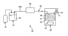
- a beer dispenser (sometimes referred to as a “beer server”) will be taken as an example for explanation (hence, hereinafter, it may be referred to as a beer dispenser 50). .).
- the beer dispenser 50 has a liquid cooling pipe (beer cooling pipe in the embodiment) 52, a refrigerator 53, and a liquid injection port 54 arranged in the cooling tank 51, and is inside the cooling tank 51.
- a part of the cooling water 55 of the above is frozen by the refrigerator 53, and the liquid (beer) 20 passing through the beer cooling pipe 52 is cooled by the cooling water 55.
- the beer 20 pumped by the carbon dioxide gas of the pressurizing source 15 passes through the beer cooling pipe 52 and is cooled by operating the lever 56 at the liquid injection port 54, and is poured into a drinking container 40 such as a mug.
- a drinking container 40 such as a mug.
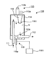
- the preventer 110 is an alternative to the blowout preventer 60 described with reference to FIG. 5, which is installed in the supply pipe 30 and has a predetermined internal volume V, as shown in FIGS. 1 and 2. It has a tubular shape, such as a cylinder or square tube, and has a liquid inlet 111 connected to the supply pipe 30 and a liquid outlet 112 connected to the supply pipe 30.
- the internal volume V is, for example, 100 cc when the pressure of the pressurized gas (carbon dioxide gas in this embodiment) is 0.4 MPa.
- Such an ejection prevention device 110 pumps beer, for example, when the beer in the beer barrel 10 is exhausted during the pouring of beer from the liquid injection port 54, that is, when the beer barrel 10 is emptied.
- the blowout preventer 110 further includes a float 116, a float push-up mechanism 118, and a mechanism motion detection sensor 1181.
- the float 116 floats on the liquid (beer in this embodiment) 20 which is arranged in the tubular shape of the blowout preventer 110 and flows into the blowout preventer 110, and moves up and down according to the amount of liquid in the blowout preventer 110. Further, the liquid 20 in the storage container 10 disappears, and the pressurized gas (the above-mentioned carbon dioxide gas in the present embodiment) flows into the blowout preventer 110 from the liquid inlet 111, so that the liquid level is pushed down. Float 116 descends.
- the float push-up mechanism 118 having such a configuration is operated after the storage container 10 is emptied and the internal volume V is filled with the liquid after the replacement with the new storage container 10, and the inside of the pipe in the liquid supply system 101 is operated. It is also operated when performing cleaning. Therefore, by detecting the operation of the float push-up mechanism, it is possible to provide the information on whether or not the inside of the pipe has been cleaned.
- the blowout preventer 110 has an exhaust mechanism 113 above the blowout preventer 110 that exhausts the pressurized gas (carbon dioxide gas in the embodiment) that has flowed into the blowout preventer 110 to the outside of the blowout preventer 110.
- the exhaust mechanism 113 is provided at least adjacent to the exhaust mechanism 113 and has a visible portion 114 capable of seeing through the inside of the blowout preventer 110.
- the exhaust mechanism 113 has an exhaust port 113a and an air bleeding lever 113b for an exhaust operation that opens and closes the exhaust port 113a. The operating function of the exhaust mechanism 113 will be described later.
- the blowout preventer 110 is formed of a transparent tubular body except for the upper and lower portions thereof, and forms the visual recognition portion 114 over almost the entire length.
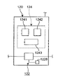
- the liquid non-detection device 120 is installed between the storage container 10 and the ejection prevention device 110 or in the ejection prevention device 110, and as shown in FIG. 3, an empty liquid that detects that the liquid in the storage container 10 has run out.
- the liquid non-detection device 120 has a nullification device 124, and the nullification device 124 has a cleaning switch 1241, a flow rate acquisition unit 1242, and a cancellation unit 1243, and more specifically, a cleaning switch 1241 and a flow rate. It has at least one of the acquisition unit 1242 and the cancellation unit 1243.
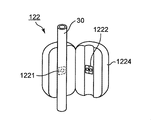
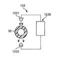
- the empty liquid / liquid passing sensor 122 has a light emitting element 1221 and a light receiving element 1222 as shown in FIGS. 4A and 4B as an example.
- the light emitting element 1221 and the light receiving element 1222 are beer passing through the supply pipe 30 in a housing 1224 arranged so as to sandwich the resin supply pipe 30 connected to the outlet of the storage container 10. They are placed facing each other with a gap between them.
- the light emitting element 1221 irradiates infrared light
- the light receiving element 1222 receives the irradiated infrared light.
- the light emitting element 1221 and the light receiving element 1222 are electrically connected to a liquid state determination unit 1226 that controls light emission and light reception thereof and detects the state of the passing liquid (beer) 20. That is, the refractive index of the light traveling from the light emitting element 1221 to the light receiving element 1222 differs depending on whether the object passing through the supply tube 30 is a liquid, a gas, or a mixture thereof. Therefore, the amount of light received by the light receiving element 1222 varies depending on the object passing through the supply tube 30.
- the liquid state determination unit 1226 detects this change in the amount of received light and determines that the passing object has become a gas.
- the liquid state determination unit 1226 is electrically connected to the transmission device 130 described below.
- a capacitance sensor (electrode sheet) may be arranged along the vertical direction on the wall surface of the blowout preventer 110.
- empty liquid / liquid passage can be detected by changing the capacitance of the liquid 20 in the blowout preventer 110 according to the water level.
- the invalidation device 124 is a device that invalidates the storage container empty information generated by cleaning the inside of the pipe in such a liquid supply system 101.
- the flow rate acquisition unit 1242 is a component that obtains the flow rate of the liquid 20 sent out from the storage container 10, and includes a flow rate sensor and a flow rate creation unit as an example.
- the flow rate sensor can be installed so as to sandwich the supply pipe 30, and for example, an ultrasonic sensor can be used.
- the flow rate creating unit is configured to obtain the flow rate of the liquid 20 based on the signal obtained from the flow rate sensor.
- each of the liquid state determination unit 1226, the flow rate acquisition unit 1242 and the cancellation unit 1243 of the invalidation device 124, and the control unit 131 of the transmission device 130 described above is actually a microprocessor. It is composed of computers such as.
- the computer is composed of software that performs the above-mentioned functions in each component, and hardware such as a CPU and a memory that execute the software.
- the operation of the liquid supply system 101 having the above configuration will be described below.
- the basic operation of the liquid supply system 101 is similar to the operation of the liquid supply system 70 shown in FIG. That is, the liquid (beer) 20 in the storage container 10 is cooled by entering the pouring device 50 through the ejection prevention device 110 by the pressurized gas (carbon dioxide gas) produced by the pressurizing source 15, and the liquid is poured by operating the lever 56. It is poured out from the outlet 54 into the drinking container 40. At this time, the liquid non-detection device 120 detects the liquid (beer) 20 as the substance flowing in the supply pipe 30.
- the pressurized gas carbon dioxide gas
- the blowout preventer 110 in the liquid supply system 101 operates as follows. Normally, the discharge port 113a is closed by operating the air bleeding lever 113b. As described above, when the liquid (beer) 20 is normally pumped from the storage container 10 to the liquid inlet 54 of the dispenser 50, the inside of the blowout preventer 110 flows in from the liquid inlet 111 and the liquid outlet 112. It is in a state of being filled with the liquid 20 discharged from the float 116, so that the float 116 is floating on the liquid 20, and the liquid 20 is flowing in this state.
- the liquid non-detection device 120 detects the difference in the refractive index of the substance passing through the supply pipe 30, detects that the liquid 20 in the storage container 10 is exhausted, and detects that the liquid 20 in the storage container 10 has run out. Empty information is transmitted to the transmission device 130.
- the liquid 20 mixed with bubbles or the pressurized gas (carbon dioxide gas) further reaches the blowout preventer 110, and the liquid 20 filling the inside of the blowout preventer 110 is discharged from the liquid outlet 112 to the injection device 50 side. It is pushed out to the supply pipe 30 of. Therefore, as the amount of liquid in the blowout preventer 110 decreases, the float 116 descends, fits into the inflow port 112a of the liquid outlet 112 of the blowout preventer 110, and closes the liquid outlet 112. In this way, the preventer 110 can prevent the pressurized gas from ejecting from the liquid inlet 54 when the beer in the beer barrel 10 runs out. In fact, when the blowout preventer 110 is activated, the store staff can recognize that the beer in the beer barrel 10 has run out, and the empty storage container 10 is replaced with a new storage container 10 filled with liquid 20. Will be exchanged for
- the liquid 20 in the new storage container 10 is introduced into the supply pipe 30, and pumping is started.
- the float 116 in the blowout preventer 110 is still fitted to the inflow port 112a of the liquid outlet 112. Therefore, when introducing the liquid, it is necessary to remove the gas (carbon dioxide gas) existing inside the blowout preventer 110, and for this purpose, the store staff operates the air bleeding lever 113b of the blowout preventer 110 to open the discharge port 113a. Open. Due to the liquid 20 that is pressure-fed and flows into the blowout preventer 110 by the operation, the gas staying in the upper part of the blowout preventer 110 and the liquid 20 mixed with bubbles are discharged from the discharge port 113a to the outside of the blowout preventer 110. The inside of the blowout preventer 110 is filled with the liquid 20 from the new storage container 10.
- the air bleeding lever 113b is operated to close the discharge port 113a.
- the store staff operates the lever 118a in the float push-up mechanism 118 of the blowout preventer 110 to mechanically push up the float 116 fitted into the inflow port 112a and forcibly separate it from the inflow port 112a. Therefore, the float 116 floats up to the liquid surface.
- the inflow port 112a is opened and connected to the liquid outlet 112. With this, the liquid supply system 101 returns to the normal operation. After that, by opening the lever 56 at the liquid injection port 54, the liquid 20 flows to the injection device 50 side through the blowout preventer 110.
- the store staff operates the cleaning switch 1241 in the liquid non-detection device 120, so that the "cleaning execution present" information generated secondarily is transmitted from the liquid non-detection device 120 to the transmission device 130.
- the transmission device 130 transmits the "cleaning execution enabled” information to the communication line 200.
- "cleaning executed” information is transmitted from the blowout preventer 110 to the transmitter 130 via the mechanism operation detection sensor 1181, and the transmitter 130 sends the transmitter 130.
- "Washing execution available" information can be transmitted to the communication line 200.
- the liquid supply system 101 of the present embodiment for example, in a beer maker having a host computer 300, it is possible to recognize for each store whether or not the cleaning operation is executed as specified in each store. It will be possible. Therefore, the quality control of the provided liquid 20 becomes possible in view of the fact that the presence or absence of the cleaning operation is related to the quality of the provided liquid 20.
- the lever 118a in the blowout preventer 110 is once again operated for the above-mentioned filling (calling) operation of the liquid 20, and the "cleaning executed" information is transmitted.
- the information can be processed by software on the host computer 300 side using, for example, elapsed time, and can be canceled.
- the liquid supply system 101 of the present embodiment at least the storage container empty information and the cleaning execution existence information transmitted from the liquid non-detection device 120 are transmitted from the transmission device 130, and therefore the liquid.
- the "freshness” control of the (eg, beer) 20 and the “pipe cleanliness” control of the liquid supply system 101 are possible, and thus the quality control of the provided liquid 20 is possible.
- the present invention is applicable to a liquid supply system in which the liquid in the storage container is pumped and discharged from the dispensing device to the drinking container.
Landscapes
- Engineering & Computer Science (AREA)
- Mechanical Engineering (AREA)
- Physics & Mathematics (AREA)
- Thermal Sciences (AREA)
- Devices For Dispensing Beverages (AREA)
- Pipeline Systems (AREA)
- Fluid-Driven Valves (AREA)
Abstract
Description
このようにしてビール樽内のビールは、顧客へ提供される。
「ビール鮮度」は、品質上、最重要事項であり、ビール樽10の開栓からビールの劣化が始まることから、ビール鮮度には開栓後の日数が影響し、またビール樽10の保管温度(つまり樽内のビール温度)も影響する。ビールメーカーでは、例えば、開栓から3日以内での消費、30℃以下での保管、を店舗へ指導している。
また「配管清浄度」は、注出ビール内の雑菌量に影響しビールの旨みと関係する。ビールメーカーでは、営業終了毎における水道水洗浄、週1回程度の配管内スポンジ洗浄を行うこと、を指導している。
即ち、本発明の第一態様における液体供給システムは、貯蔵容器内の液体を、加圧気体により供給管を通して注出装置へ供給し、該注出装置における液体注出口から飲用容器へ注出する液体供給システムであって、
上記供給管に設置され、該供給管に接続される液体入口、上記供給管に接続される液体出口、及び、上記液体入口からの気体流入により上記液体出口に嵌合して当該出口を閉鎖し上記液体注出口から加圧気体の噴出を防止するフロートを有すると共に、当該液体供給システムにおける配管内洗浄の実行有情報を提供する噴出防止装置と、
上記貯蔵容器と上記噴出防止装置との間、又は上記噴出防止装置に設置され、貯蔵容器内の液体が無くなったことを検知する空液/通液センサを有し貯蔵容器空情報を送出する液体無検出装置と、
上記液体無検出装置と電気的に接続され、通信回線への情報送信制御を行う制御部を有する送信装置と、
を備えたことを特徴とする。
)の開栓からの日数を把握することが可能になり、かつ配管内洗浄実行の有無を把握する
ことが可能になり、提供される液体の品質管理が可能になる。
尚、図1は、一実施形態における概略構成を示した図であるが、液体供給システム101の基本的構成には、通信回線200及びホストコンピュータ300は含まれない。また、液体供給システム101の基本的構成では、噴出防止装置110は、送信装置130に電気的に接続される必要はない。
また本明細書において、「電気的に接続」とは、有線接続に限定されず無線接続をも含む概念である。
各構成部分について、以下に順次説明を行っていく。
このような噴出防止装置110は、例えば、液体注出口54からビールの注出中にビール樽10内のビールが無くなった、つまりビール樽10が空になった場合に、ビールを圧送していた炭酸ガスが液体注出口54から噴出するのを防止すると共に、当該液体供給システム101における配管内洗浄の実行有情報をも提供する装置である。この点は、後述の動作説明にて詳述するが、噴出防止装置110は、液体入口111から当該噴出防止装置110内に流入した炭酸ガスが液体出口112から注出装置50側へ直接に流れるのを防止するバッファ的な役割を果たすものである。
フロート116は、当該噴出防止装置110の管状形状内に配置され噴出防止装置110内へ流入する液体(本実施形態ではビール)20に浮き、噴出防止装置110内の液体量に応じて昇降する。また、貯蔵容器10内の液体20が無くなり、液体入口111から噴出防止装置110内へ加圧気体(本実施形態では上述の炭酸ガス)が流入することで、液面が押し下げられるのに応じてフロート116は降下する。そして、流入した加圧気体が液体出口112、詳しくは液体出口112の流入口112a、から排出される直前において、フロート116は、流入口112aに嵌合し、液体出口112を閉鎖する。尚、フロート116における流入口112aとの嵌合部分には、密閉部材の一例としてのO-リング1161を設けており、嵌合における密閉性が確保される。
このようなフロート116の動作により、加圧気体が液体出口112から注出装置50側へ進入することは防止され、ビール樽10内のビールが無くなったときに、液体注出口54から加圧気体が噴出することは、防止される。またこのように、噴出防止装置110は、フロート116による機械的な遮断動作を行うことから、電気的処理を伴わず、比較的簡便な構成を採ることができるという効果もある。
このような構成を有するフロート押上機構118は、貯蔵容器10が空になり新貯蔵容器10への交換後における内部容積V内への液体充填後に操作されると共に、当該液体供給システム101における配管内洗浄を実行する際にも操作される。よって、フロート押上機構の動作検知によって、上記配管内洗浄の実行有情報が提供可能となる。
排気機構113は、本実施形態では、排出口113aと、該排出口113aの開閉を行う排気操作用のエアー抜きレバー113bとを有する。尚、排気機構113の動作機能については後述する。また本実施形態では、噴出防止装置110は、その上下部分を除いて、透明な筒状体で形成しており、ほぼ全長に渡り視認部114を形成している。
液体無検出装置120は、貯蔵容器10と噴出防止装置110との間、又は噴出防止装置110に設置され、図3に示すように、貯蔵容器10内の液体が無くなったことを検知する空液/通液センサ122及び液体状態判断部1226を有して、貯蔵容器10内の液体20が無くなったことを検知する装置である。
また一方、液体無検出装置120は、無効化装置124を有し、該無効化装置124は、洗浄スイッチ1241、流量取得部1242、及びキャンセル部1243を有し、詳しくは、洗浄スイッチ1241及び流量取得部1242の少なくとも一方と、キャンセル部1243とを有する。
液体無検出装置120におけるこれらの構成部分について、以下に詳しく説明する。
よって無効化装置124は、このような液体供給システム101における配管内洗浄によって生成される貯蔵容器空情報を無効化する装置である。
洗浄スイッチ1241は、上述の配管内洗浄を実施するにあたり操作可能なスイッチであり、専用のスイッチを設けてもよいし、例えば、噴出防止装置110における機構動作検出センサ1181と兼用することもできる。
このように、無効化装置124は、擬似的な貯蔵容器空情報を無効化することができる。
送信装置130は、少なくとも液体無検出装置120と電気的に接続され、通信回線200への情報送信制御を行う制御部131を有する。
また送信装置130は、本実施形態のように、さらに噴出防止装置110と、詳しくはフロート押上機構118における機構動作検出センサ1181と電気的に接続されてもよい。
よってこのような送信装置130は、液体無検出装置120から得られる貯蔵容器空情報、換言するとビール樽10の交換情報、及び液体供給システム101における配管内洗浄の実行有情報を、さらには噴出防止装置110から得られる配管内洗浄の実行有情報を、制御部131から通信回線200を介して、例えばビールメーカーにおけるホストコンピュータ300へ送信する。このとき、制御部131は、当該制御部131にて生成した年月日時分秒の時間情報も共に送信することができる。
液体供給システム101における基本的動作は、図5に示した液体供給システム70の動作に同様である。即ち、貯蔵容器10内の液体(ビール)20は、加圧源15による加圧気体(炭酸ガス)により噴出防止装置110を通り注出装置50へ入り、冷却され、レバー56の操作によって液体注出口54から飲用容器40へ注出される。このとき、液体無検出装置120は、供給管30内を流れる物質は、液体(ビール)20を検知している。
上述のように、貯蔵容器10から注出装置50の液体注出口54へ通常に液体(ビール)20が圧送されているときには、噴出防止装置110の内部は、液体入口111から流入し液体出口112から排出される液体20にて満たされた状態であり、よってフロート116は液体20に浮いており、この状態において液体20が流れている。
よって、ホストコンピュータ300を有する例えばビールメーカーでは、貯蔵容器10の交換が行われた日時を、店舗毎に認識することが可能になる。よって、例えばビールメーカーは、貯蔵容器10内の液体20が規定日数以内に消費されているか否かを、店舗毎に認識することが可能になり、提供する液体20の品質に消費日数が影響を与えることに鑑み、液体20の品質管理が可能になる。
このようにして、噴出防止装置110は、ビール樽10内のビールが無くなったときに液体注出口54から加圧気体が噴出するのを防止することができる。
また、実際には、噴出防止装置110が作動することで、店舗スタッフはビール樽10のビールが無くなったことを認識でき、空となった貯蔵容器10から、液体20充填済みの新しい貯蔵容器10への交換が行われる
これにて液体供給システム101は、通常動作に復帰する。
以後、液体注出口54におけるレバー56の開操作により、液体20は、噴出防止装置110を通り注出装置50側へ流れていく。
本発明は、添付図面を参照しながら好ましい実施形態に関連して充分に記載されているが、この技術の熟練した人々にとっては種々の変形や修正は明白である。そのような変形や修正は、添付した請求の範囲による本発明の範囲から外れない限りにおいて、その中に含まれると理解されるべきである。
又、2020年10月1日に出願された、日本国特許出願No.特願2020-167092号の明細書、図面、特許請求の範囲、及び要約書の開示内容の全ては、参考として本明細書中に編入されるものである。
54…液体注出口、70…液体供給システム、
101…液体供給システム、110…噴出防止装置、
111…液体入口、112…液体出口、116…フロート、
118…フロート押上機構、1181…機構動作検出センサ、
120…液体無検出装置、122…空液/通液センサ、124…無効化装置、
1241…洗浄スイッチ、1242…流量取得部、1243…キャンセル部、
130…送信装置、131…制御部、
200…通信回線。
Claims (5)
- 貯蔵容器内の液体を、加圧気体により供給管を通して注出装置へ供給し、該注出装置における液体注出口から飲用容器へ注出する液体供給システムであって、
上記供給管に設置され、該供給管に接続される液体入口、上記供給管に接続される液体出口、及び、上記液体入口からの気体流入により上記液体出口に嵌合して当該出口を閉鎖し上記液体注出口から加圧気体の噴出を防止するフロートを有すると共に、当該液体供給システムにおける配管内洗浄の実行有情報を提供する噴出防止装置と、
上記貯蔵容器と上記噴出防止装置との間、又は上記噴出防止装置に設置され、貯蔵容器内の液体が無くなったことを検知する空液/通液センサを有し貯蔵容器空情報を送出する液体無検出装置と、
上記液体無検出装置と電気的に接続され、通信回線への情報送信制御を行う制御部を有する送信装置と、
を備えたことを特徴とする、液体供給システム。 - 上記液体無検出装置は、当該液体供給システムにおける配管内洗浄の実行にあたり生成される上記貯蔵容器空情報を無効化する無効化装置を有する、請求項1に記載の液体供給システム。
- 上記無効化装置は、当該液体供給システムにおける配管内洗浄にて操作される洗浄スイッチ、又は上記貯蔵容器から送出した液体の流量を求める流量取得部を有し、配管内洗浄によって生成される上記貯蔵容器空情報を洗浄スイッチの操作によって無効化し、又は、求まる流量の合計値が貯蔵容器容量未満では配管内洗浄によって生成される上記貯蔵容器空情報を無効化する、キャンセル部をさらに有する、請求項2に記載の液体供給システム。
- 上記噴出防止装置は、上記液体出口に嵌合した上記フロートを、液体出口から強制的に離脱させるフロート押上機構と、上記送信装置と電気的に接続され、フロート押上機構の動作検知を行う機構動作検出センサと、を有する、請求項1から3のいずれかに記載の液体供給システム。
- 上記制御部は、上記液体無検出装置に加えてさらに上記噴出防止装置と電気的に接続され、液体無検出装置が送出する上記貯蔵容器空情報の送信、及び、噴出防止装置が送出する上記配管内洗浄の実行有情報の送信を行う、請求項1から4のいずれかに記載の液体供給システム。
Priority Applications (4)
| Application Number | Priority Date | Filing Date | Title |
|---|---|---|---|
| CN202180066999.8A CN116249669A (zh) | 2020-10-01 | 2021-07-28 | 液体供给系统 |
| AU2021351269A AU2021351269B2 (en) | 2020-10-01 | 2021-07-28 | Liquid supply system |
| US18/029,504 US12540068B2 (en) | 2020-10-01 | 2021-07-28 | Liquid supply system |
| EP21874880.4A EP4223690A4 (en) | 2020-10-01 | 2021-07-28 | FLUID SUPPLY SYSTEM |
Applications Claiming Priority (2)
| Application Number | Priority Date | Filing Date | Title |
|---|---|---|---|
| JP2020167092A JP7580714B2 (ja) | 2020-10-01 | 2020-10-01 | 液体供給システム |
| JP2020-167092 | 2020-10-01 |
Publications (1)
| Publication Number | Publication Date |
|---|---|
| WO2022070576A1 true WO2022070576A1 (ja) | 2022-04-07 |
Family
ID=80951294
Family Applications (1)
| Application Number | Title | Priority Date | Filing Date |
|---|---|---|---|
| PCT/JP2021/027909 Ceased WO2022070576A1 (ja) | 2020-10-01 | 2021-07-28 | 液体供給システム |
Country Status (6)
| Country | Link |
|---|---|
| US (1) | US12540068B2 (ja) |
| EP (1) | EP4223690A4 (ja) |
| JP (1) | JP7580714B2 (ja) |
| CN (1) | CN116249669A (ja) |
| AU (1) | AU2021351269B2 (ja) |
| WO (1) | WO2022070576A1 (ja) |
Citations (6)
| Publication number | Priority date | Publication date | Assignee | Title |
|---|---|---|---|---|
| US3878970A (en) * | 1974-02-11 | 1975-04-22 | Perlick Company Inc | Beer dispensing instrumentalities and method |
| EP0587344A1 (en) * | 1992-09-08 | 1994-03-16 | Guinness Brewing Worldwide Limited | A liquid dispensing system |
| JP2003261200A (ja) | 2002-03-04 | 2003-09-16 | Hoshizaki Electric Co Ltd | 飲料ディスペンサ |
| JP2004203452A (ja) * | 2002-12-26 | 2004-07-22 | Hoshizaki Electric Co Ltd | 発泡飲料自動注出装置 |
| JP2019094085A (ja) * | 2017-11-21 | 2019-06-20 | アサヒビール株式会社 | 液体販売管理装置 |
| JP2020167092A (ja) | 2019-03-29 | 2020-10-08 | 株式会社ノリタケカンパニーリミテド | 固体酸化物形燃料電池の支持体形成用材料およびその利用 |
Family Cites Families (9)
| Publication number | Priority date | Publication date | Assignee | Title |
|---|---|---|---|---|
| SE428678B (sv) * | 1981-05-25 | 1983-07-18 | Aldolf Kb | Anordning for satsvis gassettning av vetska i en behallare |
| US5674323A (en) * | 1993-02-12 | 1997-10-07 | American International, Inc. | Method and apparatus for cleaning columns by inducing vibrations in fouling material and the column |
| JPH10236591A (ja) * | 1997-02-25 | 1998-09-08 | Kirin Brewery Co Ltd | 液体注出装置の流路遮断機構 |
| WO2007053665A2 (en) | 2005-10-31 | 2007-05-10 | Ecolab Inc. | Controller-based management of a fluid dispensing system |
| AU2008334570B2 (en) * | 2007-12-12 | 2014-01-16 | Frank Hartmann | A flow control device |
| US11161729B2 (en) * | 2015-04-15 | 2021-11-02 | Sestra Systems Inc. | Empty keg detection for carbonated beverages |
| EP3162757B1 (en) | 2015-10-30 | 2018-06-20 | Carlsberg Breweries A/S | A fob detection arangement comprising a fob detection unit and comprising an insulating housing, and a method of insulating and cooling a fob detection unit |
| FR3048171B1 (fr) * | 2016-02-25 | 2018-03-30 | Kuantom | Appareil de fabrication d'une boisson |
| US10981771B2 (en) * | 2016-12-29 | 2021-04-20 | The Coca-Cola Company | Sold out detection using a level sensor for a beverage dispenser |
-
2020
- 2020-10-01 JP JP2020167092A patent/JP7580714B2/ja active Active
-
2021
- 2021-07-28 US US18/029,504 patent/US12540068B2/en active Active
- 2021-07-28 CN CN202180066999.8A patent/CN116249669A/zh active Pending
- 2021-07-28 WO PCT/JP2021/027909 patent/WO2022070576A1/ja not_active Ceased
- 2021-07-28 AU AU2021351269A patent/AU2021351269B2/en active Active
- 2021-07-28 EP EP21874880.4A patent/EP4223690A4/en active Pending
Patent Citations (6)
| Publication number | Priority date | Publication date | Assignee | Title |
|---|---|---|---|---|
| US3878970A (en) * | 1974-02-11 | 1975-04-22 | Perlick Company Inc | Beer dispensing instrumentalities and method |
| EP0587344A1 (en) * | 1992-09-08 | 1994-03-16 | Guinness Brewing Worldwide Limited | A liquid dispensing system |
| JP2003261200A (ja) | 2002-03-04 | 2003-09-16 | Hoshizaki Electric Co Ltd | 飲料ディスペンサ |
| JP2004203452A (ja) * | 2002-12-26 | 2004-07-22 | Hoshizaki Electric Co Ltd | 発泡飲料自動注出装置 |
| JP2019094085A (ja) * | 2017-11-21 | 2019-06-20 | アサヒビール株式会社 | 液体販売管理装置 |
| JP2020167092A (ja) | 2019-03-29 | 2020-10-08 | 株式会社ノリタケカンパニーリミテド | 固体酸化物形燃料電池の支持体形成用材料およびその利用 |
Non-Patent Citations (1)
| Title |
|---|
| See also references of EP4223690A4 |
Also Published As
| Publication number | Publication date |
|---|---|
| AU2021351269A1 (en) | 2023-05-18 |
| AU2021351269B2 (en) | 2026-01-29 |
| US12540068B2 (en) | 2026-02-03 |
| JP2022059385A (ja) | 2022-04-13 |
| EP4223690A1 (en) | 2023-08-09 |
| US20230365394A1 (en) | 2023-11-16 |
| JP7580714B2 (ja) | 2024-11-12 |
| CN116249669A (zh) | 2023-06-09 |
| EP4223690A4 (en) | 2024-10-30 |
Similar Documents
| Publication | Publication Date | Title |
|---|---|---|
| JP6896246B2 (ja) | 液体販売管理装置 | |
| US8657161B2 (en) | Beverages dispenser and a method for dispensing beverages | |
| WO2022070576A1 (ja) | 液体供給システム | |
| WO2019116822A1 (ja) | 液体品質管理装置 | |
| JP7522410B2 (ja) | 液体供給システム、及び液体損失低減方法 | |
| US5386927A (en) | Apparatus and method for syrup flow line clearing | |
| JP7299922B2 (ja) | 飲料供給システムの洗浄装置 | |
| JP6916490B2 (ja) | 液体販売管理システム | |
| EP1767489A2 (en) | IBeverage dispenser with purging means | |
| JP7212876B2 (ja) | 液体注出管理装置 | |
| WO2021257152A1 (en) | Fob system for intelligent flow detection and dispense control | |
| WO2020246604A1 (ja) | 飲料供給システム及び飲料枯渇通知方法 |
Legal Events
| Date | Code | Title | Description |
|---|---|---|---|
| 121 | Ep: the epo has been informed by wipo that ep was designated in this application |
Ref document number: 21874880 Country of ref document: EP Kind code of ref document: A1 |
|
| NENP | Non-entry into the national phase |
Ref country code: DE |
|
| ENP | Entry into the national phase |
Ref document number: 2021874880 Country of ref document: EP Effective date: 20230502 |
|
| ENP | Entry into the national phase |
Ref document number: 2021351269 Country of ref document: AU Date of ref document: 20210728 Kind code of ref document: A |
|
| WWG | Wipo information: grant in national office |
Ref document number: 18029504 Country of ref document: US |