WO2022070633A1 - 電力制御システムおよびプログラム - Google Patents
電力制御システムおよびプログラム Download PDFInfo
- Publication number
- WO2022070633A1 WO2022070633A1 PCT/JP2021/029823 JP2021029823W WO2022070633A1 WO 2022070633 A1 WO2022070633 A1 WO 2022070633A1 JP 2021029823 W JP2021029823 W JP 2021029823W WO 2022070633 A1 WO2022070633 A1 WO 2022070633A1
- Authority
- WO
- WIPO (PCT)
- Prior art keywords
- power consumption
- limit value
- power
- unit
- consumer
- Prior art date
- Legal status (The legal status is an assumption and is not a legal conclusion. Google has not performed a legal analysis and makes no representation as to the accuracy of the status listed.)
- Ceased
Links
Images



Classifications
-
- G—PHYSICS
- G05—CONTROLLING; REGULATING
- G05B—CONTROL OR REGULATING SYSTEMS IN GENERAL; FUNCTIONAL ELEMENTS OF SUCH SYSTEMS; MONITORING OR TESTING ARRANGEMENTS FOR SUCH SYSTEMS OR ELEMENTS
- G05B19/00—Program-control systems
- G05B19/02—Program-control systems electric
- G05B19/04—Program control other than numerical control, i.e. in sequence controllers or logic controllers
- G05B19/042—Program control other than numerical control, i.e. in sequence controllers or logic controllers using digital processors
-
- H—ELECTRICITY
- H02—GENERATION; CONVERSION OR DISTRIBUTION OF ELECTRIC POWER
- H02J—ELECTRIC POWER NETWORKS; CIRCUIT ARRANGEMENTS OR SYSTEMS FOR SUPPLYING OR DISTRIBUTING ELECTRIC POWER; SYSTEMS FOR STORING ELECTRIC ENERGY
- H02J13/00—Circuit arrangements for providing remote monitoring or remote control of equipment in a power distribution network
- H02J13/13—Circuit arrangements for providing remote monitoring or remote control of equipment in a power distribution network characterised by the transmission of data to equipment in the power network
- H02J13/1337—Circuit arrangements for providing remote monitoring or remote control of equipment in a power distribution network characterised by the transmission of data to equipment in the power network involving the use of Internet protocols
-
- G—PHYSICS
- G06—COMPUTING OR CALCULATING; COUNTING
- G06Q—INFORMATION AND COMMUNICATION TECHNOLOGY [ICT] SPECIALLY ADAPTED FOR ADMINISTRATIVE, COMMERCIAL, FINANCIAL, MANAGERIAL OR SUPERVISORY PURPOSES; SYSTEMS OR METHODS SPECIALLY ADAPTED FOR ADMINISTRATIVE, COMMERCIAL, FINANCIAL, MANAGERIAL OR SUPERVISORY PURPOSES, NOT OTHERWISE PROVIDED FOR
- G06Q10/00—Administration; Management
- G06Q10/04—Forecasting or optimisation specially adapted for administrative or management purposes, e.g. linear programming or "cutting stock problem"
-
- G—PHYSICS
- G06—COMPUTING OR CALCULATING; COUNTING
- G06Q—INFORMATION AND COMMUNICATION TECHNOLOGY [ICT] SPECIALLY ADAPTED FOR ADMINISTRATIVE, COMMERCIAL, FINANCIAL, MANAGERIAL OR SUPERVISORY PURPOSES; SYSTEMS OR METHODS SPECIALLY ADAPTED FOR ADMINISTRATIVE, COMMERCIAL, FINANCIAL, MANAGERIAL OR SUPERVISORY PURPOSES, NOT OTHERWISE PROVIDED FOR
- G06Q10/00—Administration; Management
- G06Q10/06—Resources, workflows, human or project management; Enterprise or organisation planning; Enterprise or organisation modelling
- G06Q10/063—Operations research, analysis or management
-
- G—PHYSICS
- G06—COMPUTING OR CALCULATING; COUNTING
- G06Q—INFORMATION AND COMMUNICATION TECHNOLOGY [ICT] SPECIALLY ADAPTED FOR ADMINISTRATIVE, COMMERCIAL, FINANCIAL, MANAGERIAL OR SUPERVISORY PURPOSES; SYSTEMS OR METHODS SPECIALLY ADAPTED FOR ADMINISTRATIVE, COMMERCIAL, FINANCIAL, MANAGERIAL OR SUPERVISORY PURPOSES, NOT OTHERWISE PROVIDED FOR
- G06Q50/00—Information and communication technology [ICT] specially adapted for implementation of business processes of specific business sectors, e.g. utilities or tourism
- G06Q50/06—Energy or water supply
-
- H—ELECTRICITY
- H02—GENERATION; CONVERSION OR DISTRIBUTION OF ELECTRIC POWER
- H02J—ELECTRIC POWER NETWORKS; CIRCUIT ARRANGEMENTS OR SYSTEMS FOR SUPPLYING OR DISTRIBUTING ELECTRIC POWER; SYSTEMS FOR STORING ELECTRIC ENERGY
- H02J13/00—Circuit arrangements for providing remote monitoring or remote control of equipment in a power distribution network
- H02J13/13—Circuit arrangements for providing remote monitoring or remote control of equipment in a power distribution network characterised by the transmission of data to equipment in the power network
-
- H—ELECTRICITY
- H02—GENERATION; CONVERSION OR DISTRIBUTION OF ELECTRIC POWER
- H02J—ELECTRIC POWER NETWORKS; CIRCUIT ARRANGEMENTS OR SYSTEMS FOR SUPPLYING OR DISTRIBUTING ELECTRIC POWER; SYSTEMS FOR STORING ELECTRIC ENERGY
- H02J3/00—Circuit arrangements for AC mains or AC distribution networks
- H02J3/003—Load forecast, e.g. methods or systems for forecasting future load demand
-
- H—ELECTRICITY
- H02—GENERATION; CONVERSION OR DISTRIBUTION OF ELECTRIC POWER
- H02J—ELECTRIC POWER NETWORKS; CIRCUIT ARRANGEMENTS OR SYSTEMS FOR SUPPLYING OR DISTRIBUTING ELECTRIC POWER; SYSTEMS FOR STORING ELECTRIC ENERGY
- H02J3/00—Circuit arrangements for AC mains or AC distribution networks
- H02J3/28—Arrangements for balancing of the load in networks by storage of energy
-
- G—PHYSICS
- G05—CONTROLLING; REGULATING
- G05B—CONTROL OR REGULATING SYSTEMS IN GENERAL; FUNCTIONAL ELEMENTS OF SUCH SYSTEMS; MONITORING OR TESTING ARRANGEMENTS FOR SUCH SYSTEMS OR ELEMENTS
- G05B2219/00—Program-control systems
- G05B2219/20—Pc systems
- G05B2219/26—Pc applications
- G05B2219/2639—Energy management, use maximum of cheap power, keep peak load low
-
- H—ELECTRICITY
- H02—GENERATION; CONVERSION OR DISTRIBUTION OF ELECTRIC POWER
- H02J—ELECTRIC POWER NETWORKS; CIRCUIT ARRANGEMENTS OR SYSTEMS FOR SUPPLYING OR DISTRIBUTING ELECTRIC POWER; SYSTEMS FOR STORING ELECTRIC ENERGY
- H02J2105/00—Networks for supplying or distributing electric power characterised by their spatial reach or by the load
- H02J2105/50—Networks for supplying or distributing electric power characterised by their spatial reach or by the load for selectively controlling the operation of the loads
- H02J2105/52—Networks for supplying or distributing electric power characterised by their spatial reach or by the load for selectively controlling the operation of the loads for limitation of the power consumption in the networks or in one section of the networks, e.g. load shedding or peak shaving
-
- H—ELECTRICITY
- H02—GENERATION; CONVERSION OR DISTRIBUTION OF ELECTRIC POWER
- H02J—ELECTRIC POWER NETWORKS; CIRCUIT ARRANGEMENTS OR SYSTEMS FOR SUPPLYING OR DISTRIBUTING ELECTRIC POWER; SYSTEMS FOR STORING ELECTRIC ENERGY
- H02J2105/00—Networks for supplying or distributing electric power characterised by their spatial reach or by the load
- H02J2105/50—Networks for supplying or distributing electric power characterised by their spatial reach or by the load for selectively controlling the operation of the loads
- H02J2105/52—Networks for supplying or distributing electric power characterised by their spatial reach or by the load for selectively controlling the operation of the loads for limitation of the power consumption in the networks or in one section of the networks, e.g. load shedding or peak shaving
- H02J2105/53—Networks for supplying or distributing electric power characterised by their spatial reach or by the load for selectively controlling the operation of the loads for limitation of the power consumption in the networks or in one section of the networks, e.g. load shedding or peak shaving for partial power limitation, e.g. entering degraded or current limitation modes
-
- H—ELECTRICITY
- H02—GENERATION; CONVERSION OR DISTRIBUTION OF ELECTRIC POWER
- H02J—ELECTRIC POWER NETWORKS; CIRCUIT ARRANGEMENTS OR SYSTEMS FOR SUPPLYING OR DISTRIBUTING ELECTRIC POWER; SYSTEMS FOR STORING ELECTRIC ENERGY
- H02J2105/00—Networks for supplying or distributing electric power characterised by their spatial reach or by the load
- H02J2105/50—Networks for supplying or distributing electric power characterised by their spatial reach or by the load for selectively controlling the operation of the loads
- H02J2105/54—Networks for supplying or distributing electric power characterised by their spatial reach or by the load for selectively controlling the operation of the loads according to a non-electrical condition, e.g. temperature
- H02J2105/55—Networks for supplying or distributing electric power characterised by their spatial reach or by the load for selectively controlling the operation of the loads according to a non-electrical condition, e.g. temperature according to an economic condition, e.g. tariff-based load management
-
- Y—GENERAL TAGGING OF NEW TECHNOLOGICAL DEVELOPMENTS; GENERAL TAGGING OF CROSS-SECTIONAL TECHNOLOGIES SPANNING OVER SEVERAL SECTIONS OF THE IPC; TECHNICAL SUBJECTS COVERED BY FORMER USPC CROSS-REFERENCE ART COLLECTIONS [XRACs] AND DIGESTS
- Y02—TECHNOLOGIES OR APPLICATIONS FOR MITIGATION OR ADAPTATION AGAINST CLIMATE CHANGE
- Y02B—CLIMATE CHANGE MITIGATION TECHNOLOGIES RELATED TO BUILDINGS, e.g. HOUSING, HOUSE APPLIANCES OR RELATED END-USER APPLICATIONS
- Y02B70/00—Technologies for an efficient end-user side electric power management and consumption
- Y02B70/30—Systems integrating technologies related to power network operation and communication or information technologies for improving the carbon footprint of the management of residential or tertiary loads, i.e. smart grids as climate change mitigation technology in the buildings sector, including also the last stages of power distribution and the control, monitoring or operating management systems at local level
-
- Y—GENERAL TAGGING OF NEW TECHNOLOGICAL DEVELOPMENTS; GENERAL TAGGING OF CROSS-SECTIONAL TECHNOLOGIES SPANNING OVER SEVERAL SECTIONS OF THE IPC; TECHNICAL SUBJECTS COVERED BY FORMER USPC CROSS-REFERENCE ART COLLECTIONS [XRACs] AND DIGESTS
- Y02—TECHNOLOGIES OR APPLICATIONS FOR MITIGATION OR ADAPTATION AGAINST CLIMATE CHANGE
- Y02B—CLIMATE CHANGE MITIGATION TECHNOLOGIES RELATED TO BUILDINGS, e.g. HOUSING, HOUSE APPLIANCES OR RELATED END-USER APPLICATIONS
- Y02B70/00—Technologies for an efficient end-user side electric power management and consumption
- Y02B70/30—Systems integrating technologies related to power network operation and communication or information technologies for improving the carbon footprint of the management of residential or tertiary loads, i.e. smart grids as climate change mitigation technology in the buildings sector, including also the last stages of power distribution and the control, monitoring or operating management systems at local level
- Y02B70/3225—Demand response systems, e.g. load shedding, peak shaving
-
- Y—GENERAL TAGGING OF NEW TECHNOLOGICAL DEVELOPMENTS; GENERAL TAGGING OF CROSS-SECTIONAL TECHNOLOGIES SPANNING OVER SEVERAL SECTIONS OF THE IPC; TECHNICAL SUBJECTS COVERED BY FORMER USPC CROSS-REFERENCE ART COLLECTIONS [XRACs] AND DIGESTS
- Y04—INFORMATION OR COMMUNICATION TECHNOLOGIES HAVING AN IMPACT ON OTHER TECHNOLOGY AREAS
- Y04S—SYSTEMS INTEGRATING TECHNOLOGIES RELATED TO POWER NETWORK OPERATION, COMMUNICATION OR INFORMATION TECHNOLOGIES FOR IMPROVING THE ELECTRICAL POWER GENERATION, TRANSMISSION, DISTRIBUTION, MANAGEMENT OR USAGE, i.e. SMART GRIDS
- Y04S20/00—Management or operation of end-user stationary applications or the last stages of power distribution; Controlling, monitoring or operating thereof
- Y04S20/20—End-user application control systems
- Y04S20/222—Demand response systems, e.g. load shedding, peak shaving
-
- Y—GENERAL TAGGING OF NEW TECHNOLOGICAL DEVELOPMENTS; GENERAL TAGGING OF CROSS-SECTIONAL TECHNOLOGIES SPANNING OVER SEVERAL SECTIONS OF THE IPC; TECHNICAL SUBJECTS COVERED BY FORMER USPC CROSS-REFERENCE ART COLLECTIONS [XRACs] AND DIGESTS
- Y04—INFORMATION OR COMMUNICATION TECHNOLOGIES HAVING AN IMPACT ON OTHER TECHNOLOGY AREAS
- Y04S—SYSTEMS INTEGRATING TECHNOLOGIES RELATED TO POWER NETWORK OPERATION, COMMUNICATION OR INFORMATION TECHNOLOGIES FOR IMPROVING THE ELECTRICAL POWER GENERATION, TRANSMISSION, DISTRIBUTION, MANAGEMENT OR USAGE, i.e. SMART GRIDS
- Y04S20/00—Management or operation of end-user stationary applications or the last stages of power distribution; Controlling, monitoring or operating thereof
- Y04S20/20—End-user application control systems
- Y04S20/242—Home appliances
- Y04S20/244—Home appliances the home appliances being or involving heating ventilating and air conditioning [HVAC] units
Definitions
- This disclosure relates to power control systems and programs.
- Patent Document 1 describes a plurality of grouped consumers including a power meter that measures the power consumption consumed by the load, and each of the consumers who receives the power consumption measured by the power meter from each of the consumers.
- the group power consumption is output for each group using the power consumption of, and if the group power consumption of any group exceeds the group contract power preset for each group, the group power consumption of the power excess group is calculated.
- a power control system including a control device for controlling the group contract power or less is described.
- the control for each power consumption unit is adjusted according to the power usage status of each power consumption unit in each time period, and the group.
- the purpose is to reduce unused power consumption as a whole.
- the power control system of the present disclosure is a system that controls power so as not to exceed a target power set for a group composed of a plurality of power consumption units, and the power consumption unit is based on the target power.
- the power consumption in the predetermined time based on the limit value setting means for setting the limit value of the power used in the predetermined time and the actual power consumption in the predetermined time within the predetermined time.
- a power control system comprising adjusting means for adjusting the limit value of the unit. In this way, when controlling the power consumption by a group consisting of multiple power consumption units, the control for each power consumption unit can be adjusted according to the power usage status of each power consumption unit for each time period. , It is possible to reduce unused power consumption in the entire group.
- the adjusting means has the limit value of the power consumption unit on condition that the difference between the total power consumption of the power consumption unit belonging to the group and the target power is equal to or more than a predetermined value. It may be adjusted. In this way, the limit value can be adjusted based on the total power consumption of the power consumption unit, and the unused power in the entire group can be reduced.
- the adjusting means may adjust the limit value so as to accommodate the power used between the power consumption units according to the power used in the predetermined time period by each of the power consumption units. .. In this way, the unused power in the entire group can be reduced by accommodating the available power consumption indicated by the limit value among the power consumption units.
- a control means for controlling the power consumption of the power consumption unit based on the limit value set by the limit value setting means is further provided, and the adjusting means is used by the control based on the limit value by the control means.
- the limit value of the power consumption unit may be adjusted. In this way, the limit value can be adjusted based on the control status for the power consumption unit, and the unused power in the entire group can be reduced.
- the adjusting means may adjust the limit value of the power consumption unit within a certain period retroactive from the end of the predetermined time limit. In this way, at the end of the period when the influence of the actual power demand in the power consumption unit becomes significant, the power consumption in each power consumption unit can be appropriately controlled and the unused power in the entire group can be reduced. Can be done.
- the adjusting means raises the limit value of at least a part of the power consumption units according to the power consumption in the predetermined time period by each of the power consumption units, and at least a part of the other power consumption.
- the limit value of the unit may be lowered. In this way, the unused power in the entire group can be reduced by accommodating the available power consumption indicated by the limit value among the power consumption units.
- the adjusting means does not allow the total increase in the limit value in the power consumption unit that raises the limit value to exceed the total decrease in the limit value in the power consumption unit that lowers the limit value.
- the limit value of each power consumption unit may be adjusted. By doing so, it is possible to reduce the unused power in the entire group by controlling the power consumption unit so that the total power consumption does not exceed the target power even if the limit value is adjusted.
- the power consumption unit is a consumer
- the limit value setting means determines the power consumption for a predetermined time period for each consumer based on the target power set for the group of the plurality of consumers.
- the limit value may be set, and the adjusting means may adjust the limit value of the power consumption unit in the predetermined time based on the actual power consumption in the predetermined time by the consumer. In this way, when controlling the power consumption by a group consisting of multiple consumers, the control for each consumer can be adjusted according to the power usage status of each consumer for each time period, and the entire group can be controlled. Unused power can be reduced in.
- the power consumption unit is equipment
- the limit value setting means determines the power consumption for a predetermined time period for each equipment based on the target power set for a plurality of groups of the equipment.
- the limit value may be set, and the adjusting means may adjust the limit value of the power consumption unit in the predetermined time based on the actual power consumption in the predetermined time by the equipment. In this way, when controlling the power consumption by a group consisting of multiple equipment, the control for each equipment is adjusted according to the power usage status of each equipment for each time period, and the entire group Unused power can be reduced in.
- the program of the present disclosure controls a computer that controls a system that controls power so as not to exceed a target power set for a group composed of a plurality of power consumption units, based on the target power.
- the limit value setting means for setting the limit value of the power consumption in the predetermined time limit for each consumption unit, and the said in the predetermined time limit based on the actual power consumption in the predetermined time limit.
- each power consumption unit is controlled according to the power usage status of each power consumption unit in each time period. Controls can be coordinated to reduce unused power across the group.
- FIG. 6C is a diagram showing an example of predicted values for each time period in the prediction results.
- FIG. 7 (A) is a figure which shows the forecast example for each consumer which constitutes a group
- FIG. 7 (B) is a group.
- FIG. 7C is a figure which shows the example of the prediction value for each time period in the prediction result of a group.
- FIG. 8A is a figure which shows the forecast example of the average power consumption for each time period of a group
- 8C which shows the result of allocating the limit value to each consumer, is a diagram showing an example of the limit value for each time period allocated to one customer in the group. It is a figure which shows the relationship between the target electric power of a group, and the limit value of each consumer which constitutes a group. It is a figure which shows the relationship between the limit value of each consumer in a certain time period, and the actual power consumption by each consumer. It is a figure which shows the example of the discrepancy between the target power of a group and the ultimate value of the average power consumption by each consumer. It is a figure which shows the example of the control which raises the limit value of a consumer. It is a figure which shows the relationship between the target power of a group, the initial limit value of each consumer, and the limit value after the surplus power is redistributed.
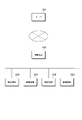
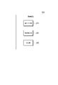
- FIG. 1 is a diagram showing an overall configuration of a control system for equipment to which this embodiment is applied.
- the control system of the present embodiment includes a control device 100, equipment 200 which is a controlled device, and a server 300.
- the control device 100 and the equipment 200 are connected to each other via a network.
- This network may be a LAN (Local Area Network) using a dedicated line, or may use a WAN (Wide Area Network), a VPN (Virtual Private Network) set on the Internet, or the like.
- LAN Local Area Network
- WAN Wide Area Network
- VPN Virtual Private Network
- Equipment 200 is equipment or equipment that operates using electric power.
- the control device 100 controls the operation of one or a plurality of equipments 200.
- FIG. 1 shows a configuration example in which the control device 100 controls a plurality of equipment 200.
- the equipment 200 may be of any type as long as it is a facility or device that operates using electric power and whose operation is controlled by the control device 100.
- the control system of the present embodiment is applied to the control of the air conditioning equipment may be described.
- the equipment 200 is provided with a control means for controlling the own device according to an instruction from the control device 100.
- the control device 100 generates an instruction for controlling the equipment 200 to be controlled (hereinafter referred to as “control instruction”), and transmits the generated control instruction to each equipment 200.
- control instruction an instruction for controlling the equipment 200 to be controlled
- Each equipment 200 acquires a control instruction from the control device 100, sets the own device according to the acquired control instruction by the control means of the own device, and controls the operation.
- the control device 100 and the server 300 are connected via a network.
- a network In the configuration example shown in FIG. 1, one control device 100 connected to the server 300 is shown, but in reality, a plurality of control devices 100 are connected to the server 300. Then, one or a plurality of equipments and devices 200 are connected to each control device 100.
- the Internet is used as the network connecting the control device 100 and the server 300. Further, LAN or WAN may be used.
- Electricity charges are mainly composed of basic charges and electricity charges, and are specified monthly.
- the basic charge is calculated based on the basic charge unit price and the contracted power.
- the contracted power is the maximum value of the maximum demand power within one year from the current month.
- the maximum demand power is the maximum value of the average power consumption for each monthly time period (demand time period: 30 minutes).
- the average power consumption is the average value of the demand power (power consumption) in each period.
- the electric energy charge is calculated based on the electric energy charge unit price and the monthly electric energy consumption.
- the contract power is the maximum value of the maximum demand power within the past year. Therefore, if the maximum demand power of a month (in other words, the average power consumption of a certain period in that month) becomes the contract power, even if the maximum demand power lower than the contract power is maintained after that month, 1 A basic charge based on this contracted electricity will be levied over the year. In addition, when the average power consumption exceeds the value of the contracted power up to that time in a certain period and becomes the maximum demand power of the month including that time period, the average power consumption (maximum demand power) of this time period becomes the new contract power. , Used to calculate the basic charge after that.
- the electric energy charge unit price may be set to fluctuate based on predetermined conditions.
- the unit price of electric energy may be set to fluctuate according to the time zone of the day, whether it is a weekday or a holiday, the season, and the like.
- electric power may be traded in the market, and a variable electric energy charge unit price may be set to reflect the transaction price of electric power in the market.
- the control may be performed with the aim of reducing the electricity charge required for the operation of the equipment 200. In this case, it is required to control the equipment 200 so that the average power consumption does not exceed the current contract power.
- the unit price of electricity fluctuates, it is more efficient to reduce the amount of electricity used in the time zone when the unit price is high than in the time zone when the unit price is low, from the viewpoint of reducing the electricity charge.
- the unit price of electricity charges affects only the electricity charges for each period, the contracted electricity affects the electricity charges for one year after the current month. Therefore, the control considering the average power consumption is prioritized over the control considering the fluctuation of the electric energy charge unit price.
- Electricity charges are levied on power supply contractors.
- a group composed of a plurality of consumers is assumed as a contractor of electric power supply. Therefore, the average power consumption is obtained as an integrated value of the average power consumption for each time period by each of the plurality of consumers constituting this group.
- the basic charge is determined based on the maximum power demand for each group (the maximum value of the average power consumption for each time period in a month).
- the maximum demand power of each group is usually smaller than the sum of the maximum demand power of each consumer constituting the group. This is because the time limit for the maximum demand power is generally different among the consumers who make up the group. Therefore, the basic charge set for the group is lower than the sum of the basic charges set based on the maximum demand power for each consumer constituting the group.
- One or more control devices 100 are assigned to one group.
- the one or more control devices 100 are set every predetermined unit time for the equipment 200 of each customer constituting the group according to the electricity charge (basic charge and electric energy charge) set in the group unit. Control is performed in consideration of the average power consumption and the unit price of electricity.
- the consumer has one or more equipment 200, and the control device 100 controls the equipment 200 of one or more consumers.
- the control device 100 controls the equipment 200 of one or more consumers.
- one consumer does not always correspond to one control device 100.
- a plurality of equipments and devices 200 possessed by one consumer may be controlled by a plurality of control devices 100, and equipments and devices 200 possessed by a plurality of consumers may be controlled by one control device 100.
- one control device 100 may be assigned to a plurality of groups. However, in the following description, for the sake of simplicity, it is assumed that one control device 100 is assigned to one customer, and the equipment 200 of each customer is controlled by the control device 100 corresponding to each customer. I will explain.
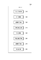
- FIG. 2 is a diagram showing the configuration of the server 300.
- the server 300 is realized as, for example, a server (so-called cloud server) built on a cloud environment of a network.
- the server 300 includes a group management unit 310, a first prediction unit 320, a limit value setting unit 330, a control information generation unit 340, a second prediction unit 350, a performance information acquisition unit 360, and a limit value adjustment unit 370. And a transmission control unit 380.
- the group management unit 310 manages the above-mentioned group of consumers. As mentioned above, this group is set as a unit of power contract. The group management unit 310 acquires and holds information on the contracted power of the group, the maximum demand power, and the average power consumption for each time period. In addition, the group management unit 310 manages the consumers who make up the group. The group management unit 310 acquires and holds information on the contracted power, the maximum demand power, and the average power consumption for each time period of each consumer constituting the group. Information on the average power consumption of each consumer is obtained, for example, from the control device 100 that controls the equipment 200 of each consumer.
- the information on the average power consumption of the group is obtained from, for example, the control device 100 that controls the equipment 200 of the consumers constituting the group (hereinafter referred to as "equipment 200 of the group”).
- equipment 200 of the group the equipment 200 of the group
- the average power consumption for each time period of each consumer constituting the group is integrated to obtain the average power consumption of the group.
- the first prediction unit 320 predicts the average power consumption for each time period by the equipment 200 of each customer for each customer constituting the group.
- the first prediction unit 320 is an example of a prediction means.
- the prediction of the average power consumption for each time period by the first prediction unit 320 is performed, for example, based on the historical information regarding the past operation of the equipment 200 of each consumer constituting the group.
- the history information regarding the operation includes various information related to the operation of the equipment 200, such as information on the operating environment of the equipment 200, in addition to the information on the operating state of the equipment 200.
- Information on the operating state of the equipment 200 includes, for example, information such as an operating rate, continuous operating time, and the number of operating times.
- the information on the operating environment includes, for example, weather conditions such as weather, temperature, and humidity, and information such as month, day, and time zone.
- a reference time period for the specific time period is set based on historical information on operation, and the equipment 200 in this reference time period. It may be done based on the average power consumption of.
- the reference time limit may be, for example, a past time limit which is a weather condition similar to the weather condition expected at the date and time when the specific time limit corresponds, or a corresponding time limit on the same day of the same month one year ago.
- the average power consumption of the equipment 200 in the time before and after the reference time and the average power of the equipment 200 in the time period of several days up to the day including the reference time You may take into consideration the transition of power consumption.
- the limit value setting unit 330 sets a limit value for each customer constituting the group with respect to the average power consumption for each time period by the equipment 200 of each consumer based on the prediction result by the first prediction unit 320.
- the limit value setting unit 330 is an example of setting means. If the average power consumption of a group exceeds the contracted power of the group, this average power consumption becomes a new contracted power and raises the basic charge of electricity charges. Therefore, it is required to set a target power based on the contract power for the group and control the average power consumption for each time period so as not to exceed the target power in the entire equipment 200 of the group. Then, the limit value for each time limit is set so that the integrated value of the limit value of each consumer is equal to or less than the threshold value based on the target power.
- the target power is set to a value equal to or less than the contract power, for example, a value lower than the contract power by a certain value.
- the threshold value is set to a value equal to or less than the target power, for example, a value lower than the target power by a certain value.
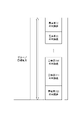
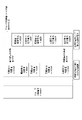
- FIG. 9 is a diagram showing the relationship between the target power of the group and the limit value of each consumer constituting the group.
- the value of the target power and the above threshold value are equal to each other, and the value is compared with the integrated value of the limit value of each consumer.
- the value obtained by integrating the limit values of the 12 consumers (customers (1) to (12)) does not exceed the target power of the group composed of each consumer. It is shown that.
- the electric power corresponding to the target electric power set for the group is distributed to each consumer constituting the group.
- each consumer constituting the group is an example of a power consumption unit.
- the limit value of each of the consumers constituting the group is set based on, for example, the prediction of the average power consumption for each consumer by the first prediction unit 320. From the prediction of the first prediction unit 320, the ratio of the average power consumption predicted by each consumer of the group is specified for each time period. Therefore, for example, when the integrated value of the limit value of each consumer is set to be equal to the threshold value based on the above target power, the average power consumption corresponding to this threshold value is predicted by the first prediction unit 320. Allocate the power so that it is the ratio of the average power consumption by the consumers, and use it as the limit value for each consumer. In other words, the limit value means the power consumption available to each consumer in that time period.
- the limit value is set based on the actual value of the average power consumption for each time period in the past specific period of each customer, instead of the ratio of the average power consumption for each time period for each consumer. good.
- the ratio of the actual value of the average power consumption of each consumer in the reference time period shown in the same explanation is specified with respect to the specific time period shown in the explanation of the prediction by the first prediction unit 320.
- a limit value for each consumer in a specific time period may be set based on the ratio of the actual value.
- the specific period may be set according to the amount of information obtained as the actual value of the reference time period, for example, set for the past one year or several years, or between a specific date and a specific date. You may.
- the limit value may be set based on the maximum value of the average power consumption for each time period in a specific period of each consumer. For example, assuming that the specific period is the past one year, the maximum value of the average power consumption for each time period in the past one year can be obtained for each consumer. Then, the maximum value of each consumer may be compared, and the limit value of each consumer may be set at a ratio according to the ratio. In this case, unlike the case where the actual value of the reference time is used, the time when the average power consumption becomes the maximum value may be different for each consumer.
- a lower limit value may be set as the limit value.
- the lower limit is a value greater than 0.
- a limit value corresponding to the lower limit value is set even when the average power consumption in a certain time period is predicted to be 0 for a certain consumer. This is because when the average power consumption is predicted to be 0 for a certain consumer and the limit value is set to 0, the limit value is immediately exceeded when the consumer uses the equipment 200 in that time limit. Therefore, this is to avoid such inconvenience.
- the case where the average power consumption is predicted to be 0 may be, for example, the case where the average power consumption of the consumer in the reference time period used for the prediction by the first prediction unit 320 is 0.
- the lower limit setting method may be appropriately determined according to the operation and specifications of the control system, the agreement between the group and individual consumers, and the like. For example, a fixed value may be set in advance, or a value that fluctuates based on a predicted value of the average power consumption for each time period in the entire group may be used. When a fixed value is set as the lower limit value, the same value may be set for each consumer, or a separate value may be set for each consumer according to appropriate conditions and demands of the consumer.
- the predicted value of the average power consumption for each time period in the entire group is obtained by integrating the predicted value of the average power consumption for each time period in each consumer constituting the group by the first prediction unit 320.
- the lower limit threshold value is set for the limit value, and when the limit value given to a certain consumer is lower than the lower limit value, the lower limit value is applied as the limit value. Is also good.
- a value different from the lower limit value may be set. For example, if a value lower than the lower limit value is set as the lower limit threshold value, when the limit value assigned to a certain customer falls below the lower limit threshold value in a certain time period, the lower limit value larger than the lower limit threshold value is the demand in that time period. Set as a house limit.
- a limit value is set for the average power consumption of each time period by the equipment 200 for each customer.
- a configuration in which a limit value is set only for the average power consumption for a period satisfying a specific condition may be used. For example, by integrating the predicted values of the average power consumption of a certain time period in each consumer constituting the group by the first prediction unit 320, the predicted value of the average power consumption of the entire group in that time period can be obtained.
- a limit value may be set only for the average power consumption in such a time period, provided that the predicted value of the average power consumption of this group exceeds the above threshold value.
- the threshold is set based on the target power, and the target power is set based on the contract power. Therefore, when many of the consumers who make up a group do not use a large amount of power in a certain time period (for example, the time zone from midnight to dawn), the predicted value of the average power consumption of the group for that time period has a large threshold value. It is possible that it will fall below. In such a case, set the limit value of each consumer in the group to a value higher than the predicted value of the average power consumption of each consumer within the range where the integrated value of the limit value of each consumer does not exceed the threshold value. May be.
- the control information generation unit 340 generates control information for controlling the equipment 200 of each consumer constituting the group.
- the control information includes the equipment 200 in the control device 100 so that the average power consumption for each time period by the equipment 200 of the consumer does not exceed the time limit set by the limit value setting unit 330. Information to be controlled. Therefore, the control information includes information on the limit value for each consumer set by the limit value setting unit 330.
- the control information generation unit 340 generates the control information of the corresponding time period before the time period in which the control by each control information is performed is started.
- control information generation unit 340 controls the equipment 200 to control the adjustment result of the limit value when the limit value of each consumer set by the limit value setting unit 330 is adjusted by the limit value adjustment unit 370.
- general control information when distinguishing between the above control information based on the limit value set by the limit value setting unit 330 and the control information based on the limit value adjusted by the limit value adjustment unit 370, the former is referred to as “general control information”.
- the latter is called “individual control information”.
- the adjustment of the limit value by the limit value adjustment unit 370 is performed within the time limit in which the control to reflect the adjustment of the limit value is performed. Therefore, unlike the general control information, the individual control information is generated within the time period after the time period in which the control by the individual control information is performed is started.
- the second prediction unit 350 predicts the average power consumption of the equipment 200 in the current time within the currently ongoing time period (hereinafter referred to as “current time”) in which the control of the equipment 200 is being carried out. ..
- the prediction of the average power consumption by the second prediction unit 350 is performed, for example, based on the information regarding the operating status of the equipment 200 of each consumer within the current time limit.
- the information on the operating status includes, for example, information such as the transition of the power consumption of the equipment 200 from the start of the current time limit to the predicted time within the time limit, the amount of power used, the operating state, and the setting related to the operation. ..
- the operation-related settings are specifically selected according to the type of equipment 200. For example, when the equipment 200 is an air conditioner, information such as a difference between the set temperature and the actual room temperature can be used.
- the performance information acquisition unit 360 acquires performance information regarding the operating status of the equipment 200 of each customer constituting the group. In addition to the above-mentioned actual information in the current time period (actual information from the start of the current time period to the time when the actual information is acquired), the acquired actual information is acquired in the already completed time period. Is also good.
- the performance information may be acquired from the control device 100 that controls the equipment 200, or may be acquired from the equipment 200 itself.
- the actual information of the current time period acquired by the actual information acquisition unit 360 is used for the prediction of the average power consumption of the equipment 200 by the second prediction unit 350, the adjustment of the limit value by the limit value adjustment unit 370, and the like.
- the limit value adjustment unit 370 adjusts the limit value of each consumer constituting the group set by the limit value setting unit 330 based on a predetermined condition. As an example, the limit value adjustment unit 370 adjusts the limit value of each consumer based on the prediction by the second prediction unit 350. Further, as another example, the limit value adjusting unit 370 adjusts the limit value of each consumer based on the actual information regarding the operating status of the equipment 200 in the current time period acquired by the actual information acquisition unit 360. The adjustment of the limit value is adjusted so that the power consumption available to each consumer is interchanged among the consumers who make up the group. For example, the limit value is lowered for some of the consumers constituting the group, and the limit value is raised for other consumers by the amount corresponding to the decrease in the limit value of some consumers. Details of adjusting the limit value will be described later.
- the transmission control unit 380 transmits the control information generated by the control information generation unit 340 to the control device 100 that controls the equipment 200 of the consumer corresponding to each control information.
- the transmission control unit 380 transmits the general control information of the corresponding time period to the control device 100 before the time period in which the control by each control information is performed is started.
- the transmission control unit 380 immediately before the time period to transmit the general control information to be reduced from the power consumption in the time period immediately before the time period to be transmitted. It may be possible to transmit before the general control information that is increased from the power consumption in the time limit.
- the transmission control unit 380 immediately transmits the individual control information to the control device 100 that controls the equipment 200 to be controlled by the generated individual control information.
- the transmission control unit 380 transmits the individual control information to the control device 100, the individual control information for the equipment 200 whose limit value is lowered by the adjustment is obtained from the individual control information for the equipment 200 whose limit value is increased by the adjustment. May be sent first.
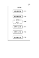
- FIG. 3 is a diagram showing the configuration of the control device 100.
- the control device 100 is realized as an information processing device connected to the server 300 and the equipment 200 via a network.
- the control device 100 may be a device (for example, an edge server) provided in the vicinity of the equipment 200 to be controlled, or may be a server (cloud server) built on a cloud environment.
- the control device 100 includes a control information acquisition unit 110, an operation information acquisition unit 120, a storage unit 130, a control instruction generation unit 140, a control instruction output unit 150, and an operation information output unit 160.
- the control information acquisition unit 110 acquires the control information of the equipment 200 from the server 300.
- the control information acquired by the control information acquisition unit 110 includes general control information acquired before the start of the time period and individual control information acquired during the progress of the time period as control information for a certain time period. be.
- the general control information includes information on the average power consumption limit value set for each consumer.
- the individual control information includes information on new limit values that adjust the limit values contained in the general control information for the ongoing time limit.
- the operation information acquisition unit 120 acquires the operation information of the equipment 200 to be controlled by the control device 100.
- the operation information acquired by the operation information acquisition unit 120 broadly includes various information regarding the operation of the equipment 200. For example, it includes information indicating an operating state such as an operating rate and continuous operating time of the equipment 200. In addition, it may include various information that is considered to affect the operation of the equipment 200, such as the operating time zone, the operation on weekdays and the operation on holidays. Further, the operation information acquisition unit 120 may acquire information on the environment in which the equipment 200 is installed, such as temperature and humidity. This information can be obtained by various existing methods depending on the type of information. For example, it can be obtained from the equipment 200 itself, or it can be obtained from various sensor devices and the like. Further, the date and time information can be obtained by, for example, a clock function or a calendar function provided in the control device 100.
- the storage unit 130 stores various types of information acquired by the control information acquisition unit 110 and the operation information acquisition unit 120.
- the control information acquired by the control information acquisition unit 110 is used to control the equipment 200.
- the general control information of each time period is stored in the storage unit 130 before the time period in which the control by each general control information is performed is started.
- the operation information of the equipment 200 acquired by the operation information acquisition unit 120 is sent to the server 300 at a predetermined timing, and is used for the prediction by the first prediction unit 320 and the second prediction unit 350 of the server 300.
- the control instruction generation unit 140 generates a control instruction for controlling the equipment 200 based on the control information acquired by the control information acquisition unit 110.
- the control instruction generation unit 140 issues a control instruction to operate the equipment 200 so that the average power consumption for each time period by the equipment 200 of each consumer does not exceed the limit value set for the customer for each time period. Generate.
- the integrated value of the average power consumption of all the equipment 200 possessed by the one consumer does not exceed the corresponding time limit for each time period.
- Control instructions are generated. In this case, there is no particular limitation on the method in which the consumer allocates electric power to his / her own plurality of equipment 200 in order not to exceed the limit value set for the consumer.
- control instruction generation unit 140 may generate a control instruction in consideration of the operation information of the equipment 200 acquired by the operation information acquisition unit 120. Of the control information acquired by the control information acquisition unit 110, the control instruction generated by the control instruction generation unit 140 based on the general control information is held in the storage unit 130.
- the control instruction output unit 150 has a time limit in which the control instruction generated by the control instruction generation unit 140 based on the general control information is controlled by the general control information among the control information acquired by the control information acquisition unit 110. Is read from the storage unit 130 and transmitted to the equipment 200 to be controlled. Further, the control instruction output unit 150 immediately sends the control instruction generated by the control instruction generation unit 140 based on the individual control information among the control information acquired by the control information acquisition unit 110 to the equipment device 200 to be controlled. Send.
- the operation information output unit 160 reads the operation information of the equipment 200 acquired by the operation information acquisition unit 120 and held in the storage unit 130 from the storage unit 130 and transmits it to the server 300 according to a predetermined condition.
- the operation information may be read and transmitted in response to a request from the server 300, or may be periodically performed at a fixed time of the day or the like.
- FIG. 4 is a diagram showing a hardware configuration example of the control device 100 and the server 300.
- the control device 100 and the server 300 are realized by, for example, a computer. Even when the control device 100 and the server 300 are realized as a server constructed in a cloud environment, they are configured as a virtual system using the system resources of a physical computer as shown in FIG. 4 on the network. To.
- a computer that realizes the control device 100 includes a CPU (Central Processing Unit) 101 that is a calculation means, a RAM (RandomAccessMemory) 102, a ROM (ReadOnlyMemory) 103, and a storage device 104 that are storage means.
- the RAM 102 is a main storage device (main memory), and is used as a working memory when the CPU 101 performs arithmetic processing. Data such as a program and a set value prepared in advance are stored in the ROM 103, and the CPU 101 can directly read the program and the data from the ROM 103 and execute the process.
- the storage device 104 is a means for storing programs and data.
- a program is stored in the storage device 104, and the CPU 101 reads the program stored in the storage device 104 into the main storage device and executes the program. Further, the storage device 104 stores and stores the result of processing by the CPU 101.
- the storage device 104 for example, a magnetic disk device, an SSD (Solid State Drive), or the like is used.
- control information acquisition unit 110 When the control device 100 is realized by the computer shown in FIG. 4, the control information acquisition unit 110, the operation information acquisition unit 120, the control instruction generation unit 140, the control instruction output unit 150, and the operation information output are described with reference to FIG.
- Each function of the unit 160 is realized, for example, by the CPU 101 executing a program.
- the storage unit 130 is realized by, for example, a RAM 102 or a storage device 104.
- the server 300 is realized by the computer shown in FIG. 4, the group management unit 310, the first prediction unit 320, the limit value setting unit 330, the control information generation unit 340, and the second prediction unit described with reference to FIG. 2 are used.
- Each function of the unit 350, the performance information acquisition unit 360, the limit value adjustment unit 370, and the transmission control unit 380 is realized, for example, by the CPU 101 executing a program.
- the configuration example shown in FIG. 4 is only an example of the case where the control device 100 is realized by a computer.
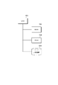
- FIG. 5 is a diagram showing the configuration of the equipment 200.
- the equipment 200 includes a receiving unit 210, an operation control unit 220, and an output unit 230.
- the equipment 200 has a mechanism or an apparatus that operates to realize the function of the equipment 200 according to the type of the equipment 200.
- the equipment 200 is an air conditioner
- the equipment 200 has an indoor unit, an outdoor unit, and the like.
- the equipment 200 is a lighting equipment
- the equipment 200 has a lighting equipment, a control switch, and the like. Since the types and modes of such a mechanism and the like vary depending on the type of equipment 200, they are not shown here.
- the receiving unit 210 receives the control instruction output from the control device 100 via the network using a network interface (not shown).
- the operation control unit 220 controls the operation of the mechanism or device provided in the equipment 200 based on the control instruction received by the reception unit 210. Specifically, for example, when the equipment 200 is an air-conditioning device, the receiving unit 210 receives information for specifying the set temperature as a control instruction, and the operation control unit 220 receives the indoor unit and the indoor unit so that the received set temperature is reached. Control the operation of the outdoor unit. Although an example of control related to temperature setting is given here, control by the operation control unit 220 is performed for various controls related to gas that can be controlled by the air conditioner (for example, control of humidity and gas components). Instructional controls may be applied. Further, in various equipment 200 other than the air conditioning equipment, the operation control unit 220 executes control according to the type of the equipment 200 according to the control instruction received from the control device 100.
- the output unit 230 outputs information regarding the operating state of the equipment 200 to the control device 100 via the network using a network interface (not shown).
- the receiving unit 210, the operation control unit 220, and the output unit 230 are realized by, for example, a computer.
- the computer that realizes the motion control unit 220 may have the configuration described with reference to FIG.
- the functions of the receiving unit 210, the operation control unit 220, and the output unit 230 are realized, for example, by the CPU 101 shown in FIG. 4 executing the program.
- the functions of the receiving unit 210, the operation control unit 220, and the output unit 230 may be realized by dedicated hardware.
- it is realized by an ASIC (Application Specific Integrated Circuit), an FPGA (Field-Programmable Gate Array), and other circuits.
- the function realized by the CPU 101 executing the program (software) and the function realized by the dedicated hardware may be combined to form the receiving unit 210, the operation control unit 220, and the output unit 230.
- a group composed of a plurality of consumers is targeted for a contract, and the contract power is set based on the average power consumption for each time period of each group.
- the average power consumption for each time period in this group unit will be further described with reference to the drawings.
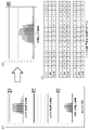
- FIG. 6 is a diagram showing an example of forecasting the power consumption of one consumer.
- FIG. 6A is a diagram showing an example of past actual power consumption
- FIG. 6B is a diagram showing a prediction result of daily power consumption
- FIG. 6C is a prediction value for each time period in the prediction result. It is a figure which shows the example of.
- the horizontal axis is the time period (48 time period) for one day (24 hours)
- the vertical axis is the average power consumption (kW) for each time period.
- the graphs of FIGS. 6A and 6B and the table of FIG. 6C show the actual and predicted results of the average power consumption of the equipment 200 in each time period of the day.
- FIGS. 6A to 6C show the actual results and forecast results of the entire equipment 200 owned by the consumer and the actual results and forecast of the air conditioner among the equipment 200 with respect to the equipment 200 of one consumer. The result is shown.
- FIG. 6A shows the actual average power consumption for each time period for 3 days (3 days ago, 2 days ago, and 1 day ago) before the day when the power consumption is to be predicted.
- the light-colored graph shows the actual results of the equipment 200 as a whole
- the dark-colored graph shows the actual results of the air-conditioning equipment.
- FIG. 6B shows an example of the prediction result of the average power consumption for each time period predicted in consideration of the actual results as shown in FIG. 6A.
- the light-colored graph shows the prediction result of the entire equipment 200
- the dark-colored graph shows the prediction result of the air-conditioning equipment.
- 6C shows the average of the entire equipment 200 (in the figure, it is described as a “building” representing the facility where each equipment 200 is installed) in each time period (1st to 48th time periods) of the day.
- the predicted value of the power consumption and the predicted value of the average power consumption of the air conditioner in the equipment 200 are shown in association with each other.
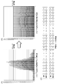
- FIG. 7 is a diagram showing an integrated example of forecasting power consumption of a group composed of a plurality of consumers.
- FIG. 7 (A) is a diagram showing an example of forecast for each consumer constituting the group
- FIG. 7 (B) is a diagram showing the forecast result of the entire group
- FIG. 7 (C) is a forecast for each time period in the forecast result of the group. It is a figure which shows the example of a value.
- the horizontal axis is the time period (48 time period) for one day (24 hours)
- the vertical axis is the average power consumption (kW) for each time period.
- FIG. 7 (C) show the forecast results of the average power consumption of consumers and groups in each time period of the day.
- the forecast result of the average power consumption of the entire equipment 200 of each consumer is referred to as the forecast result of the average power consumption of the consumer or the forecast result of the consumer.
- FIG. 7 (A) shows the forecast result of the average power consumption for each time period for each of the consumers constituting the group.
- FIG. 7A shows only the prediction results of three consumers (customers (1) to (3)) among the plurality of consumers constituting the group, and the others are omitted.
- the light-colored graph shows the prediction result of the entire equipment 200
- the dark-colored graph shows the prediction result of the air-conditioning equipment.
- FIG. 7B shows the prediction result of the average power consumption for each time period in the entire group including the three consumers shown in FIG. 7A.
- the graph classification (color coding) of each time period indicates that the predicted value of the average power consumption of each consumer constituting the group is integrated in each time period.
- FIG. 7C shows an integrated value of the prediction result of the average power consumption of each consumer in each time period (1st time period to 48th time period) of the day.
- the target power of this group (described as “target value” in the figure) is set to 1000 kW, and referring to FIGS. 7 (B) and 7 (C), the average of the entire group is from the 22nd period to the 31st period.
- the predicted power consumption exceeds the target power. Therefore, at least in these time periods, a limit value is set for the power consumption of each consumer constituting the group so that the predicted value of the average power consumption of the entire group does not exceed the target power.
- the limit value itself for each consumer may be set not only in the time period in which the predicted value of the entire group exceeds the target power, but also in other time periods in which the predicted value of the entire group does not exceed the target power.
- FIG. 8 is a diagram showing an example of setting a limit value for each consumer constituting the group.
- FIG. 8A is a diagram showing an example of forecasting average power consumption for each time period of the group
- FIG. 8B is a diagram showing the distribution result of the limit value to each consumer constituting the group
- FIG. 8C is a diagram.
- It is a figure which shows the example of the limit value for each time period allocated to one consumer of a group.
- the horizontal axis is the time period (48 time period) for one day (24 hours)
- the vertical axis is the average power consumption (kW) for each time period.
- FIG. 8A shows the forecast result of the average power consumption for each time period for each of the consumers constituting the group.
- This graph is the same as the graph shown in FIG. 7 (B).
- FIG. 8B shows an example of the distribution result of the limit value set for each consumer constituting the group when the average power consumption in each time period of the group is aligned with the target power. ..
- the graph classification (color coding) of each time period represents the ratio of the limit value (power consumption available to that consumer) distributed to each consumer in each time period.
- the ratio of the limit value allocated to each consumer in each time period is, in principle, the ratio of the predicted value of the average power consumption of each consumer in the prediction of the average power consumption of the group shown in FIG. 8 (A).
- a lower limit value may be given as a limit value instead of the ratio of the predicted value of the average power consumption.
- one of the consumers constituting the group (customer (1)) is allocated to each time period (1st to 48th time periods) of the day. Limits are shown.
- a limit value for the average power consumption of each customer is set before the corresponding time period is started.
- the equipment 200 of each consumer is controlled based on the limit value.
- the limit value of each consumer is adjusted as necessary, and the control of the equipment 200 within the time limit is changed.
- the adjustment of this limit value will be further described with reference to the drawings. In the following example, the case where the value of the target power and the threshold value based on the target power are equal and the integrated value of the limit value of each consumer constituting the group is controlled to be equal to or less than the target power of the group will be described.
- FIG. 10 is a diagram showing the relationship between the limit value of each consumer in a certain time period and the actual power consumption by each consumer.
- a group is composed of 5 consumers (customers (1) to (5)).
- the target power of a group of a certain time period (14:00 to 14:30 in the figure) is 900 kW
- the limit value of the consumer (1) is 200 kW
- the limit value of the consumer (2) is set to 50 kW
- the limit value of the consumer (3) is set to 100 kW
- the limit value of the consumer (4) is set to 300 kW
- the limit value of the consumer (5) is set to 250 kW.
- FIG. 10 shows a graph showing an example of the actual power consumption of the consumer (1) and the consumer (4) constituting the group.
- the horizontal axis is a time period (30 minutes)
- the vertical axis is the average power consumption for that time period estimated from the actual power demand up to each time point with the passage of time.
- the power consumption for one period is shown by a line that reaches the value of the average power consumption at the end of the time period. In this graph, if the power consumption is constant for one period, the power consumption graph becomes a straight line.
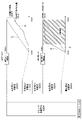
- the graphs of the illustrated consumer (1) and consumer (4) show a straight line C that reaches the limit value of each consumer at the end of the time period and a curve P that represents the actual value, respectively.
- the limit value of the consumer (1) in the time limit (14:00 to 14:30) is 200 kW. Therefore, the straight line C in the graph of the consumer (1) is a straight line reaching 200 kW at the end of the time limit (14:30).
- the actual power demand of the consumer (1) shown in FIG. 10 is smaller than the average power consumption corresponding to the limit value. Therefore, the curve P of the actual value deviates downward from the straight line C.
- the average power consumption value (final value) of this time period specified at the end of the time period (14:30) was 160 kW. Therefore, the actual value of the average power consumption of the consumer (1) in this time limit is 40 kW lower than the limit value. Referring to the graph of the consumer (1) in FIG. 10, the final value deviates below the limit value.
- the limit value of the consumer (4) in the time limit (14:00 to 14:30) is 300 kW. Therefore, the straight line C in the graph of the consumer (4) is a straight line reaching 300 kW at the end of the time limit (14:30).
- the actual power demand of the consumer (4) shown in FIG. 10 is larger than the average power consumption corresponding to the limit value at the beginning of the time limit. Therefore, the curve P of the actual value deviates upward from the straight line C.
- the average power consumption in this time period exceeds the limit value of the consumer (4).
- control for suppressing the power consumption of the equipment 200 of the consumer (4) is performed from the middle of the time limit.
- the shaded portion is the time zone in which the suppression control is performed.
- the deviation from the same limit value is the average usage of each consumer. Can occur with respect to power.
- the final value of the average power consumption in the time limit is usually the limit value. It fits below.
- the power consumption in the middle of the time limit falls below the limit value
- the final value of the average power consumption in the time limit deviates downward from the limit value. Then, in the entire group, the value obtained by integrating the deviation value between the actual average power consumption of each consumer and the limit value is the deviation from the target power of the group.
- FIG. 11 is a diagram showing an example of the deviation between the target power of the group and the final value of the average power consumption by each consumer.
- the consumers constituting the group, the target power of the group, and the limit values set for each consumer are the same as the example shown in FIG.
- the final value of the average power consumption in the consumer (1) (described as "power consumption” in the figure) was 160 kW, which was 40 kW lower than the limit value of 200 kW.
- the final value of the average power consumption in the consumer (2) was 49 kW, which was almost the same as the limit value.
- the final value of the average power consumption in the consumer (3) was 98 kW, which was almost the same as the limit value.
- the final value of the average power consumption in the consumer (4) was 299 kW, which was almost the same as the limit value.
- the final value of the average power consumption in the consumer (5) was 200 kW, which was 50 kW lower than the limit value of 250 kW. Therefore, the integrated value of the final value of the average power consumption by each consumer is 90 kW or more lower than the target power of the group.
- the discrepancy between the target power of this group and the integrated value of the final value of the average power consumption by each consumer represents the surplus power that was available but not used by the consumers who make up the group. Then, when the equipment 200 of the consumer (2), the consumer (3), and the consumer (4) has almost no discrepancy between the limit value and the final value of the average power consumption, the suppression control is performed. Although there is surplus power in the entire group, suppression control is performed for each individual consumer, which causes a decrease in control efficiency for the equipment 200. Therefore, when such surplus power is generated, it is conceivable to redistribute the surplus power to the consumer whose suppression control is performed.
- the reallocation of surplus power is performed, for example, by resetting the limit value of each consumer constituting the group. Specifically, among the consumers that make up the group, the limit value of some consumers whose actual power consumption is lower than the limit value is lowered, and the limit value of some consumers whose suppression control is performed. Increase the value. So to speak, the available power consumption is shared among the consumers who make up the group. In this case, the integrated value of the increase range of the limit value in each consumer who raises the limit value is set to be equal to or less than the integrated value of the decrease range of the limit value in each consumer who lowers the limit value. As a result, it is possible to prevent the integrated value of the average power consumption of each consumer constituting the group from exceeding the target power of the group.
- FIG. 12 is a diagram showing an example of control for raising the limit value of the consumer.
- the consumers constituting the group, the target power of the group, and the limit values set for each consumer are the same as the example shown in FIG.
- the suppression control is performed for the consumer (2), the consumer (3), and the consumer (4).
- FIG. 12 shows a graph showing an example of the actual power consumption for the consumer (2). Similar to the graph shown in FIG. 10, in this graph, the horizontal axis is the time period (30 minutes), and the vertical axis is the average power consumption in that time period estimated from the actual power demand up to each time point with the passage of time. It is a graph to do.
- the control for raising the limit value of the consumer is performed, for example, by stopping the suppression control in the target consumer.
- the straight line C in the graph of the consumer (2) shown in FIG. 12 is a straight line reaching 50 kW at the end of the time limit (14:30).
- the actual power demand of the consumer (2) is larger than the average power consumption corresponding to the limit value at the beginning of the time limit. Therefore, the curve P of the actual value deviates upward from the straight line C. Therefore, as shown in FIG. 12, suppression control is performed on the equipment 200 of the consumer (2) from the middle of the time limit. As a result, the curve P of the actual value approaches the straight line C. After that, when the limit value is adjusted and the suppression control is stopped, the curve P of the actual value deviates upward from the straight line C again.
- the shaded portion is the time zone in which the suppression control is performed.
- the suppression control is started in the middle of the time limit, and the suppression control is stopped 5 minutes before the end time (14:30) (14:25).
- Control to raise the limit value is performed in the latter half of the time limit, as illustrated in FIG. Specifically, it is performed within a certain period going back from the end of the time limit. This is because after confirming that the suppression control has been executed due to the discrepancy between the actual power consumption in the first half of the time limit and the initial limit value, the limit value is increased.
- the control for increasing the limit value was executed 5 minutes before the end of the time limit as described above.
- the time shown in FIG. 12 is merely an example, and the timing of starting and stopping the suppression control depends on the type and operating status of the equipment 200 to be controlled, the specifications and operation of the control device 100 and the entire system, and the like. It is determined individually based on.
- FIG. 13 is a diagram showing the relationship between the target power of the group, the initial limit value of each consumer, and the limit value after the surplus power is redistributed.
- the consumers constituting the group, the target power of the group, and the initial limit values set for each consumer are the same as the example shown in FIG.
- the suppression control is performed on the equipment 200 of the consumer (2), the consumer (3), and the consumer (4) as in the example shown in FIG.
- the limit value for redistributing the surplus power is reset.
- the deviation (decrease) of the actual power consumption with respect to the initial limit value is 40 kW.
- the difference (decrease) in the actual power consumption with respect to the initial limit value is 50 kW. Therefore, the surplus power of the entire group is 90 kW.
- half of the electric power corresponding to the deviation width between the consumer (1) and the consumer (5) in which the actual decrease in the actual power consumption with respect to these initial limit values is recognized, the consumer whose suppression control is performed (the consumer (1)). 2), allocate to consumers (3) and consumers (4).
- the electric power is allocated according to the ratio of the initial limit value in each consumer of the allocation destination.
- the power of 45 kW which is 1/2 of 90 kW, is the ratio of the initial limit value of 50 kW for the consumer (2), the initial limit value of 100 kW for the consumer (3), and the initial limit value of 300 kW for the consumer (4). It is distributed to the consumer (2) at 5 kW, the consumer (3) at 10 kW, the consumer (4) at 30 kW, and so on.
- the reset limit value of each consumer is as shown in FIG.
- the above-mentioned method for resetting the limit value is merely an example, and the method for resetting the limit value and redistributing the surplus power is not limited to the above-mentioned specific method.
- the power to be distributed is not limited to 1/2 of the surplus power.
- the distribution of electric power to each consumer does not have to be the ratio of the initial limit value of each consumer as described above.
- the number of consumers to be distributed (3 consumers in the example of FIG. 13). It may be divided into equal parts according to the situation.
- surplus power can be distributed and limit values can be reset by various methods.
- the execution conditions for the allocation of surplus power and the resetting of the limit value can be variously determined based on the power consumption of each consumer constituting the group within the time limit and the integrated value thereof. For example, it may be an execution condition that the difference between the target power of the group and the integrated value of the power used by each consumer becomes equal to or more than a predetermined value at a certain point in the time limit. Further, it may be an execution condition that the suppression control is performed on the equipment 200 of any customer within the time limit. Further, these events may be combined as an execution condition. In addition, conditions can be set individually in a specific control system.
- the electric power corresponding to the target electric power set for the group is distributed to each consumer constituting the group, and is configured as a control system for controlling the electric power usage by the equipment 200 of each consumer.
- the control system of the present embodiment has various configurations in which power corresponding to the target power set for a group consisting of a plurality of power consumption units is distributed to each power consumption unit. Applicable.
- the control system of the present embodiment can be applied to a configuration in which one or more consumers distribute the electric power allocated to them to their own plurality of equipment 200.
- a plurality of equipment 200s owned by one consumer form one group, and each equipment 200 is a power consumption unit.
- the control device 100 that controls the equipment 200 of one consumer distributes and controls the electric power in the range of the limit value given to the consumer to each equipment 200.
- the distribution of electric power to each equipment 200 can be performed, for example, in the same manner as the server 300 predicting the electric power used by each equipment 200 for each time period and setting a limit value for each customer. Therefore, in such control, a limit value (power used by each equipment 200) is set for each equipment 200.
- control device 100 determines whether or not the integrated value of the actual power consumption of the equipment 200 deviates from the limit value of the consumer based on the actual operating condition of each equipment 200 within the time limit (surplus). Whether or not power is being generated) is determined. Then, when surplus power is generated, the limit value of each equipment 200 is adjusted so that the power used by each equipment 200 can be interchanged between the equipment 200s.
- a plurality of equipments and devices 200 owned by one customer are distributed and installed in a plurality of facilities, and the electric power allocated to the customer is distributed to the facilities in which the equipments and devices 200 are installed.
- the control system of the present embodiment may be applied.
- a plurality of facilities in which the equipment 200 of one consumer is installed form one group, and each facility is a power consumption unit.
- the control device 100 that controls the equipment 200 of one consumer distributes and controls the electric power in the range of the limit value given to the consumer to the facility where the equipment 200 is installed.
- the distribution of electric power to each facility is performed in the same manner as the server 300 described above sets a limit value for each customer by predicting the electric power used by the equipment 200 installed in each facility for each time period, for example.
- a limit value (power consumption available in each facility) for each facility is set for each facility.
- the integrated value of the actual power consumption of the equipment 200 for each facility deviates from the limit value of the consumer based on the actual operating condition of the equipment 200 in each facility within the time limit. Whether or not (whether or not surplus power is generated) is determined. Then, when surplus power is generated, the limit value of each facility is adjusted so that the power used in each facility can be interchanged between the facilities.
- the limit value can be set before the start of the time limit in which the control based on the control information is performed, and the limit value can be adjusted after the start of the time limit, but before the start of the time limit. May not set a limit value, but may set a limit value according to the operating status of the equipment 200 within the time limit. Further, in the above embodiment, the limit value after the start of the time limit is adjusted in the server 300, but the limit value may be adjusted in the control device 100.
- the power control system of the present disclosure is a system that controls power so as not to exceed a target power set for a group composed of a plurality of power consumption units, and is based on the target power for each power consumption unit.
- the limit value setting unit 330 that sets the limit value of the power consumption in the predetermined time period, and the limit of the power consumption unit in the predetermined time period based on the actual power consumption in the predetermined time period.
- It is a power control system including a limit value adjusting unit 370 for adjusting a value. In this way, when controlling the power consumption by a group consisting of multiple power consumption units, the control for each power consumption unit can be adjusted according to the power usage status of each power consumption unit for each time period. , It is possible to reduce unused power consumption in the entire group.
- the limit value adjusting unit 370 adjusts the limit value of the power consumption unit on condition that the difference between the total power consumption of the power consumption unit belonging to the group and the target power is equal to or more than a predetermined value. It's fine as a matter of fact. In this way, the limit value can be adjusted based on the total power consumption of the power consumption unit, and the unused power in the entire group can be reduced.
- the limit value adjusting unit 370 may adjust the limit value so as to accommodate the power consumption between the power consumption units according to the power consumption in a predetermined time period by each of the power consumption units. In this way, the unused power in the entire group can be reduced by accommodating the available power consumption indicated by the limit value among the power consumption units.
- a control device 100 for controlling the power consumption of the power consumption unit based on the limit value set by the limit value setting means is further provided, and the limit value adjusting unit 370 is controlled by the control device 100 based on the power consumption. If there is a power consumption unit in which the power consumption unit is suppressed, the limit value of the power consumption unit may be adjusted. In this way, the limit value can be adjusted based on the control status for the power consumption unit, and the unused power in the entire group can be reduced.
- the limit value adjusting unit 370 may adjust the limit value of the power consumption unit within a certain period retroactive from the end of the predetermined time limit. In this way, at the end of the period when the influence of the actual power demand in the power consumption unit becomes significant, the power consumption in each power consumption unit can be appropriately controlled and the unused power in the entire group can be reduced. Can be done.
- the limit value adjusting unit 370 raises the limit value of at least a part of the power consumption units according to the power consumption in a predetermined time period by each of the power consumption units, and limits the limit value of at least some other power consumption units. It may be possible to lower the value. In this way, the unused power in the entire group can be reduced by accommodating the available power consumption indicated by the limit value among the power consumption units.
- the limit value adjusting unit 370 is provided with each so that the total increase in the limit value in the power consumption unit that raises the limit value does not exceed the total decrease in the limit value in the power consumption unit that lowers the limit value. It may be possible to adjust the limit value of the power consumption unit. By doing so, it is possible to reduce the unused power in the entire group by controlling the total power consumption in the power consumption unit within a range that does not exceed the target power even if the limit value is adjusted.
- the power consumption unit is a consumer
- the limit value setting unit 330 is a limit value of the power consumption for a predetermined time period for each consumer based on the target power set for a group of a plurality of consumers. May be set, and the limit value adjusting unit 370 may adjust the limit value of the power consumption unit in the predetermined time limit based on the actual power consumption within the predetermined time limit by the consumer. In this way, when controlling the power consumption by a group consisting of multiple consumers, the control for each consumer can be adjusted according to the power usage status of each consumer for each time period, and the entire group can be controlled. Unused power can be reduced in.
- the power consumption unit is equipment
- the limit value setting unit 330 sets the limit value of the power used for a predetermined time period for each equipment based on the target power set for the group of a plurality of equipment. May be set, and the limit value adjusting unit 370 may adjust the limit value of the power consumption unit in the predetermined time limit based on the actual power consumption within the predetermined time limit by the equipment. In this way, when controlling the power consumption by a group consisting of multiple equipment, the control for each equipment is adjusted according to the power usage status of each equipment for each time period, and the entire group Unused power can be reduced in.
- the program of the present disclosure is a power consumption unit based on a computer that controls a system that controls a system that controls power so as not to exceed a target power set for a group composed of a plurality of power consumption units.
- the power consumption unit in the predetermined time period based on the limit value setting unit 330 that sets the limit value of the power consumption in the predetermined time period and the actual power consumption in the predetermined time period within the predetermined time period.
- each power consumption unit is controlled according to the power usage status of each power consumption unit in each time period. Controls can be coordinated to reduce unused power across the group.
Landscapes
- Engineering & Computer Science (AREA)
- Business, Economics & Management (AREA)
- Human Resources & Organizations (AREA)
- Economics (AREA)
- Strategic Management (AREA)
- Physics & Mathematics (AREA)
- Power Engineering (AREA)
- General Physics & Mathematics (AREA)
- Theoretical Computer Science (AREA)
- Tourism & Hospitality (AREA)
- Entrepreneurship & Innovation (AREA)
- General Business, Economics & Management (AREA)
- Marketing (AREA)
- Game Theory and Decision Science (AREA)
- Quality & Reliability (AREA)
- Health & Medical Sciences (AREA)
- Operations Research (AREA)
- Development Economics (AREA)
- Automation & Control Theory (AREA)
- Water Supply & Treatment (AREA)
- General Health & Medical Sciences (AREA)
- Public Health (AREA)
- Primary Health Care (AREA)
- Educational Administration (AREA)
- Supply And Distribution Of Alternating Current (AREA)
- Remote Monitoring And Control Of Power-Distribution Networks (AREA)
- Management, Administration, Business Operations System, And Electronic Commerce (AREA)
- Direct Current Feeding And Distribution (AREA)
- Selective Calling Equipment (AREA)
- Control Of Eletrric Generators (AREA)
Abstract
Description
このようにすれば、複数の電力消費単位からなるグループによる使用電力に対して制御を行う場合に、時限ごとにおける個々の電力消費単位の電力使用状況に応じて各電力消費単位に対する制御を調整し、グループ全体における不使用の電力を削減することができる。
このようにすれば、電力消費単位の使用電力の合計に基づいて制限値を調整し、グループ全体における不使用の電力を削減することができる。
このようにすれば、電力消費単位どうしの間で制限値により示される利用可能な使用電力を融通し合うことにより、グループ全体における不使用の電力を削減することができる。
このようにすれば、電力消費単位に対する制御状況に基づいて制限値を調整し、グループ全体における不使用の電力を削減することができる。
このようにすれば、電力消費単位における電力需要の実績の影響が顕著となる時限の終盤において、電力消費単位ごとの使用電力の制御を適切に行い、グループ全体における不使用の電力を削減することができる。
このようにすれば、電力消費単位どうしの間で制限値により示される利用可能な使用電力を融通し合うことにより、グループ全体における不使用の電力を削減することができる。
このようにすれば、制限値を調整しても電力消費単位の使用電力の合計が目標電力を超えない範囲で制御を行うことにより、グループ全体における不使用の電力を削減することができる。
このようにすれば、複数の需要家からなるグループによる使用電力に対して制御を行う場合に、時限ごとにおける個々の需要家の電力使用状況に応じて各需要家に対する制御を調整し、グループ全体における不使用の電力を削減することができる。
このようにすれば、複数の設備機器からなるグループによる使用電力に対して制御を行う場合に、時限ごとにおける個々の設備機器の電力使用状況に応じて各設備機器に対する制御を調整し、グループ全体における不使用の電力を削減することができる。
このプログラムをインストールしたコンピュータによれば、複数の電力消費単位からなるグループによる使用電力に対して制御を行う場合に、時限ごとにおける個々の電力消費単位の電力使用状況に応じて各電力消費単位に対する制御を調整し、グループ全体における不使用の電力を削減することができる。
<システム構成>
図1は、本実施形態が適用される設備機器の制御システムの全体構成を示す図である。本実施形態の制御システムは、制御装置100と、被制御装置である設備機器200と、サーバ300とを備える。制御装置100と設備機器200とは、ネットワークを介して接続されている。このネットワークは、専用回線によるLAN(Local Area Network)であっても良いし、WAN(Wide Area Network)やインターネット上に設定されたVPN(Virtual Private Network)等を用いても良い。
ここで、電気料金について説明する。電気料金は、主に基本料金と電力量料金とにより構成され、月ごとに特定される。基本料金は、基本料金単価と契約電力とに基づいて計算される。契約電力は、当月から遡って1年以内の最大需要電力の最大値とされる。最大需要電力とは、月間の時限(デマンド時限:30分)ごとの平均使用電力の最大値である。平均使用電力とは、各時限における需要電力(使用電力)の平均値である。また、電力量料金は、電力量料金単価と月ごとの使用電力量とに基づいて計算される。
図2は、サーバ300の構成を示す図である。サーバ300は、例えば、ネットワークのクラウド環境上に構築されたサーバ(いわゆるクラウドサーバ)等として実現される。サーバ300は、グループ管理部310と、第1予測部320と、制限値設定部330と、制御情報生成部340と、第2予測部350と、実績情報取得部360と、制限値調整部370と、送信制御部380とを備える。
図3は、制御装置100の構成を示す図である。制御装置100は、ネットワークを介してサーバ300および設備機器200と接続された情報処理装置として実現される。制御装置100は、制御対象の設備機器200の近隣に設けられた装置(例えば、エッジサーバ)であっても良いし、クラウド環境上に構築されたサーバ(クラウドサーバ)であっても良い。制御装置100は、制御情報取得部110と、稼働情報取得部120と、記憶部130と、制御指示生成部140と、制御指示出力部150と、稼働情報出力部160とを備える。
図4は、制御装置100およびサーバ300のハードウェア構成例を示す図である。制御装置100およびサーバ300は、例えば、コンピュータにより実現される。制御装置100およびサーバ300がクラウド環境に構築されたサーバとして実現される場合であっても、ネットワーク上の図4に示すような物理的なコンピュータのシステムリソースを用いた仮想的なシステムとして構成される。
図5は、設備機器200の構成を示す図である。設備機器200は、受け付け部210と、動作制御部220と、出力部230とを備える。なお、設備機器200は、その種類に応じて、設備機器200の機能を実現するために動作する機構や装置を有している。例えば、設備機器200が空調機器である場合、設備機器200は、室内機および室外機等を有する。また、設備機器200が照明設備である場合、設備機器200は、照明器具や制御スイッチ等を有する。このような機構等の種類や態様は、設備機器200の種類に応じて様々であるため、ここでは図示しない。
本実施形態では、複数の需要家により構成されるグループを契約対象とし、グループ単位の時限ごとの平均使用電力に基づいて契約電力を設定する。このグループ単位の時限ごとの平均使用電力について、図面を参照してさらに説明する。
本実施形態では、グループを構成する各需要家の設備機器200に対する制御が行われる時限ごとに、該当する時限が開始される前に、各需要家の平均使用電力に対する制限値が設定され、かかる制限値に基づいて各需要家の設備機器200が制御される。一方、該当する時限が開始されると、必要に応じて、各需要家の制限値が調整され、時限内における設備機器200の制御が変更される。この制限値の調整について、図面を参照してさらに説明する。以下の例では、目標電力の値と目標電力に基づく閾値とが等しく、グループを構成する各需要家の制限値の積算値がグループの目標電力以下となるように制御される場合について説明する。
需要家(1)が180kW(=200-40÷2)、
需要家(2)が55kW(=50+45÷(50+100+300)×50)、
需要家(3)が110kW(=100+45÷(50+100+300)×100)、
需要家(4)が330kW(=300+45÷(50+100+300)×300)、
需要家(5)が225kW(=250-50÷2)
となる。
上記の実施形態では、グループに対して設定された目標電力に相当する電力を、グループを構成する各需要家に配分し、各需要家の設備機器200による電力使用を制御する制御システムとして構成した例について説明した。本実施形態の制御システムは、上記の構成の他、複数の電力消費単位からなるグループに対して設定された目標電力に相当する電力を各電力消費単位に配分するような種々の構成に対して適用し得る。
このようにすれば、複数の電力消費単位からなるグループによる使用電力に対して制御を行う場合に、時限ごとにおける個々の電力消費単位の電力使用状況に応じて各電力消費単位に対する制御を調整し、グループ全体における不使用の電力を削減することができる。
このようにすれば、電力消費単位の使用電力の合計に基づいて制限値を調整し、グループ全体における不使用の電力を削減することができる。
このようにすれば、電力消費単位どうしの間で制限値により示される利用可能な使用電力を融通し合うことにより、グループ全体における不使用の電力を削減することができる。
このようにすれば、電力消費単位に対する制御状況に基づいて制限値を調整し、グループ全体における不使用の電力を削減することができる。
このようにすれば、電力消費単位における電力需要の実績の影響が顕著となる時限の終盤において、電力消費単位ごとの使用電力の制御を適切に行い、グループ全体における不使用の電力を削減することができる。
このようにすれば、電力消費単位どうしの間で制限値により示される利用可能な使用電力を融通し合うことにより、グループ全体における不使用の電力を削減することができる。
このようにすれば、制限値を調整しても電力消費単位の使用電力の合計が目標電力を超えない範囲で制御を行うことにより、グループ全体における不使用の電力を削減することができる。
このようにすれば、複数の需要家からなるグループによる使用電力に対して制御を行う場合に、時限ごとにおける個々の需要家の電力使用状況に応じて各需要家に対する制御を調整し、グループ全体における不使用の電力を削減することができる。
このようにすれば、複数の設備機器からなるグループによる使用電力に対して制御を行う場合に、時限ごとにおける個々の設備機器の電力使用状況に応じて各設備機器に対する制御を調整し、グループ全体における不使用の電力を削減することができる。
このプログラムをインストールしたコンピュータによれば、複数の電力消費単位からなるグループによる使用電力に対して制御を行う場合に、時限ごとにおける個々の電力消費単位の電力使用状況に応じて各電力消費単位に対する制御を調整し、グループ全体における不使用の電力を削減することができる。
Claims (10)
- 複数の電力消費単位により構成されたグループを対象として設定された目標電力を超えないように電力制御するシステムであって、
前記目標電力に基づいて、前記電力消費単位ごとに、所定の時限の使用電力の制限値を設定する制限値設定手段と、
前記所定の時限内において、当該所定の時限内における使用電力の実績に基づいて、当該所定の時限における前記電力消費単位の前記制限値を調整する調整手段と、
を備える、電力制御システム。 - 前記調整手段は、前記グループに属する前記電力消費単位の使用電力の合計と前記目標電力との差分が予め定められた値以上であることを条件として、前記電力消費単位の前記制限値を調整する、請求項1に記載の電力制御システム。
- 前記調整手段は、前記電力消費単位の各々による前記所定の時限における使用電力に応じて、当該電力消費単位の間で使用電力を融通し合うように前記制限値を調整する、請求項1または請求項2に記載の電力制御システム。
- 前記制限値設定手段により設定された前記制限値に基づいて前記電力消費単位の使用電力を制御する制御手段をさらに備え、
前記調整手段は、前記制御手段による前記制限値に基づく制御によって使用電力が抑制される前記電力消費単位がある場合に、当該電力消費単位の前記制限値の調整を行う、請求項1乃至請求項3に記載の電力制御システム。 - 前記調整手段は、前記所定の時限の終了時から遡る一定の期間内に、前記電力消費単位の前記制限値の調整を行う、請求項1乃至請求項4の何れかに記載の電力制御システム。
- 前記調整手段は、前記電力消費単位の各々による前記所定の時限における使用電力に応じて、少なくとも一部の前記電力消費単位の前記制限値を上昇させ、少なくとも他の一部の前記電力消費単位の前記制限値を低下させる、請求項1乃至請求項5の何れかに記載の電力制御システム。
- 前記調整手段は、前記制限値を上昇させる電力消費単位における当該制限値の上昇幅の合計が、前記制限値を低下させる電力消費単位における当該制限値の低下幅の合計を超えないように、各電力消費単位の制限値を調整する、請求項6に記載の電力制御システム。
- 前記電力消費単位が需要家であり、
前記制限値設定手段は、複数の前記需要家のグループに対して設定された目標電力に基づいて、需要家ごとに、所定の時限の使用電力の制限値を設定し、
前記調整手段は、前記需要家による前記所定の時限内における使用電力の実績に基づいて、当該所定の時限における前記電力消費単位の前記制限値を調整する、請求項1に記載の電力制御システム。 - 前記電力消費単位が設備機器であり、
前記制限値設定手段は、複数の前記設備機器のグループに対して設定された目標電力に基づいて、設備機器ごとに、所定の時限の使用電力の制限値を設定し、
前記調整手段は、前記設備機器による前記所定の時限内における使用電力の実績に基づいて、当該所定の時限における前記電力消費単位の前記制限値を調整する、請求項1に記載の電力制御システム。 - 複数の電力消費単位により構成されたグループを対象として設定された目標電力を超えないように電力制御するシステムを制御するコンピュータを、
前記目標電力に基づいて、前記電力消費単位ごとに、所定の時限の使用電力の制限値を設定する制限値設定手段と、
前記所定の時限内において、当該所定の時限内における使用電力の実績に基づいて、当該所定の時限における前記電力消費単位の前記制限値を調整する調整手段として、
機能させる、プログラム。
Priority Applications (6)
| Application Number | Priority Date | Filing Date | Title |
|---|---|---|---|
| CN202180066358.2A CN116325408A (zh) | 2020-09-30 | 2021-08-13 | 电力控制系统和程序 |
| US18/029,186 US12093007B2 (en) | 2020-09-30 | 2021-08-13 | Power control system and program |
| AU2021353150A AU2021353150B2 (en) | 2020-09-30 | 2021-08-13 | Power control system and program |
| EP21874936.4A EP4224655A4 (en) | 2020-09-30 | 2021-08-13 | ENERGY REGULATION PROGRAM AND SYSTEM |
| BR112023005777A BR112023005777A2 (pt) | 2020-09-30 | 2021-08-13 | Sistema de controle de energia, e, programa |
| MX2023003691A MX2023003691A (es) | 2020-09-30 | 2021-08-13 | Sistema y programa de control de energia. |
Applications Claiming Priority (2)
| Application Number | Priority Date | Filing Date | Title |
|---|---|---|---|
| JP2020165452A JP7152678B2 (ja) | 2020-09-30 | 2020-09-30 | 電力制御システムおよびプログラム |
| JP2020-165452 | 2020-09-30 |
Publications (1)
| Publication Number | Publication Date |
|---|---|
| WO2022070633A1 true WO2022070633A1 (ja) | 2022-04-07 |
Family
ID=80949964
Family Applications (1)
| Application Number | Title | Priority Date | Filing Date |
|---|---|---|---|
| PCT/JP2021/029823 Ceased WO2022070633A1 (ja) | 2020-09-30 | 2021-08-13 | 電力制御システムおよびプログラム |
Country Status (8)
| Country | Link |
|---|---|
| US (1) | US12093007B2 (ja) |
| EP (1) | EP4224655A4 (ja) |
| JP (1) | JP7152678B2 (ja) |
| CN (1) | CN116325408A (ja) |
| AU (1) | AU2021353150B2 (ja) |
| BR (1) | BR112023005777A2 (ja) |
| MX (1) | MX2023003691A (ja) |
| WO (1) | WO2022070633A1 (ja) |
Families Citing this family (6)
| Publication number | Priority date | Publication date | Assignee | Title |
|---|---|---|---|---|
| CN112524746B (zh) * | 2019-09-17 | 2021-11-26 | 青岛海尔空调电子有限公司 | 多联机空调系统中室外机均衡结霜的控制方法 |
| JP7116348B2 (ja) * | 2020-09-30 | 2022-08-10 | ダイキン工業株式会社 | 電力制御システムおよびプログラム |
| JP2023148975A (ja) | 2022-03-30 | 2023-10-13 | 日本碍子株式会社 | ハニカム構造体、電気加熱型担体及び排気ガス浄化装置 |
| US11817711B1 (en) | 2022-03-30 | 2023-11-14 | United Services Automobile Association (Usaa) | Systems and methods for adjusting electric power to devices |
| US12283813B1 (en) * | 2022-03-30 | 2025-04-22 | United Services Automobile Association (Usaa) | Systems and methods for adjusting electric power distributed to consumers |
| US20240403125A1 (en) * | 2024-08-13 | 2024-12-05 | Lemon Inc. | Method, device, and medium for placing information |
Citations (3)
| Publication number | Priority date | Publication date | Assignee | Title |
|---|---|---|---|---|
| JP2001211547A (ja) * | 2000-01-27 | 2001-08-03 | Hitachi Ltd | 電力供給方法 |
| JP2003032887A (ja) * | 2001-07-12 | 2003-01-31 | Nippon Telegr & Teleph Corp <Ntt> | 広域電力融通取引方法および広域電力融通取引システム |
| JP2019030087A (ja) | 2017-07-27 | 2019-02-21 | 東京瓦斯株式会社 | 電力制御システム |
Family Cites Families (15)
| Publication number | Priority date | Publication date | Assignee | Title |
|---|---|---|---|---|
| JPS5440135B2 (ja) * | 1974-01-30 | 1979-12-01 | ||
| JPS63121431A (ja) * | 1986-11-07 | 1988-05-25 | 株式会社日立製作所 | 最大需要電力調整装置 |
| JP2002247757A (ja) * | 2001-02-16 | 2002-08-30 | Mitsubishi Electric Corp | デマンド監視制御システム |
| JP2003022887A (ja) * | 2001-07-09 | 2003-01-24 | Midori Anzen Co Ltd | コロナ放電装置の異常検出装置及びコロナ放電装置の異常検出方法 |
| WO2008111467A1 (ja) * | 2007-03-09 | 2008-09-18 | Sanyo Electric Co., Ltd. | デマンド制御システム、デマンドコントローラ、デマンドプログラム及びデマンド制御方法 |
| JP5758763B2 (ja) * | 2011-09-29 | 2015-08-05 | 三菱電機株式会社 | 電力制御システム、全体電力制御装置、個別電力制御装置及び電力制御方法 |
| US20130211752A1 (en) * | 2012-02-14 | 2013-08-15 | Wayne State University | Software power analysis |
| WO2013157030A1 (ja) | 2012-04-16 | 2013-10-24 | 日立コンシューマエレクトロニクス株式会社 | 電力監視装置および電力監視システム |
| JP5914860B2 (ja) * | 2012-10-12 | 2016-05-11 | パナソニックIpマネジメント株式会社 | 管理装置 |
| JP6302197B2 (ja) * | 2013-09-20 | 2018-03-28 | 株式会社東芝 | 電力需給制御装置及び電力需給制御方法 |
| US10677484B2 (en) * | 2015-05-04 | 2020-06-09 | Johnson Controls Technology Company | User control device and multi-function home control system |
| WO2017131026A1 (ja) | 2016-01-26 | 2017-08-03 | 日本電気株式会社 | 電力管理装置及びシステムと方法並びにプログラム |
| US10754334B2 (en) * | 2016-05-09 | 2020-08-25 | Strong Force Iot Portfolio 2016, Llc | Methods and systems for industrial internet of things data collection for process adjustment in an upstream oil and gas environment |
| JP6778891B2 (ja) * | 2016-08-08 | 2020-11-04 | パナソニックIpマネジメント株式会社 | 電力管理システム、電力管理方法及びプログラム |
| WO2022054442A1 (ja) * | 2020-09-11 | 2022-03-17 | 株式会社Ihi | 電力調整方法および電力調整装置 |
-
2020
- 2020-09-30 JP JP2020165452A patent/JP7152678B2/ja active Active
-
2021
- 2021-08-13 MX MX2023003691A patent/MX2023003691A/es unknown
- 2021-08-13 WO PCT/JP2021/029823 patent/WO2022070633A1/ja not_active Ceased
- 2021-08-13 BR BR112023005777A patent/BR112023005777A2/pt not_active Application Discontinuation
- 2021-08-13 EP EP21874936.4A patent/EP4224655A4/en active Pending
- 2021-08-13 CN CN202180066358.2A patent/CN116325408A/zh active Pending
- 2021-08-13 US US18/029,186 patent/US12093007B2/en active Active
- 2021-08-13 AU AU2021353150A patent/AU2021353150B2/en active Active
Patent Citations (3)
| Publication number | Priority date | Publication date | Assignee | Title |
|---|---|---|---|---|
| JP2001211547A (ja) * | 2000-01-27 | 2001-08-03 | Hitachi Ltd | 電力供給方法 |
| JP2003032887A (ja) * | 2001-07-12 | 2003-01-31 | Nippon Telegr & Teleph Corp <Ntt> | 広域電力融通取引方法および広域電力融通取引システム |
| JP2019030087A (ja) | 2017-07-27 | 2019-02-21 | 東京瓦斯株式会社 | 電力制御システム |
Non-Patent Citations (1)
| Title |
|---|
| See also references of EP4224655A4 |
Also Published As
| Publication number | Publication date |
|---|---|
| CN116325408A (zh) | 2023-06-23 |
| AU2021353150B2 (en) | 2023-09-28 |
| EP4224655A1 (en) | 2023-08-09 |
| US20230273580A1 (en) | 2023-08-31 |
| JP2022057283A (ja) | 2022-04-11 |
| MX2023003691A (es) | 2023-04-21 |
| US12093007B2 (en) | 2024-09-17 |
| BR112023005777A2 (pt) | 2023-04-25 |
| AU2021353150A1 (en) | 2023-05-18 |
| JP7152678B2 (ja) | 2022-10-13 |
| EP4224655A4 (en) | 2024-04-10 |
| AU2021353150A9 (en) | 2024-02-08 |
Similar Documents
| Publication | Publication Date | Title |
|---|---|---|
| WO2022070633A1 (ja) | 電力制御システムおよびプログラム | |
| JP7103925B2 (ja) | 電力管理方法および電力管理システム | |
| JP2022113860A (ja) | 電力制御システムおよびプログラム | |
| JP7104345B2 (ja) | 電力制御システムおよびプログラム | |
| JP7093033B2 (ja) | 電力制御システム | |
| JP7116348B2 (ja) | 電力制御システムおよびプログラム | |
| JP2023004714A (ja) | 制御装置およびプログラム |
Legal Events
| Date | Code | Title | Description |
|---|---|---|---|
| 121 | Ep: the epo has been informed by wipo that ep was designated in this application |
Ref document number: 21874936 Country of ref document: EP Kind code of ref document: A1 |
|
| WWE | Wipo information: entry into national phase |
Ref document number: 202317022675 Country of ref document: IN |
|
| WWE | Wipo information: entry into national phase |
Ref document number: 2021353150 Country of ref document: AU |
|
| REG | Reference to national code |
Ref country code: BR Ref legal event code: B01A Ref document number: 112023005777 Country of ref document: BR |
|
| ENP | Entry into the national phase |
Ref document number: 112023005777 Country of ref document: BR Kind code of ref document: A2 Effective date: 20230328 |
|
| NENP | Non-entry into the national phase |
Ref country code: DE |
|
| ENP | Entry into the national phase |
Ref document number: 2021874936 Country of ref document: EP Effective date: 20230502 |
|
| ENP | Entry into the national phase |
Ref document number: 2021353150 Country of ref document: AU Date of ref document: 20210813 Kind code of ref document: A |