WO2022070834A1 - 脊椎固定具用ロッド - Google Patents
脊椎固定具用ロッド Download PDFInfo
- Publication number
- WO2022070834A1 WO2022070834A1 PCT/JP2021/033268 JP2021033268W WO2022070834A1 WO 2022070834 A1 WO2022070834 A1 WO 2022070834A1 JP 2021033268 W JP2021033268 W JP 2021033268W WO 2022070834 A1 WO2022070834 A1 WO 2022070834A1
- Authority
- WO
- WIPO (PCT)
- Prior art keywords
- reinforcing fiber
- fiber
- layer
- rod
- fiber layer
- Prior art date
- Legal status (The legal status is an assumption and is not a legal conclusion. Google has not performed a legal analysis and makes no representation as to the accuracy of the status listed.)
- Ceased
Links
Images




Classifications
-
- A—HUMAN NECESSITIES
- A61—MEDICAL OR VETERINARY SCIENCE; HYGIENE
- A61B—DIAGNOSIS; SURGERY; IDENTIFICATION
- A61B17/00—Surgical instruments, devices or methods
- A61B17/56—Surgical instruments or methods for treatment of bones or joints; Devices specially adapted therefor
- A61B17/58—Surgical instruments or methods for treatment of bones or joints; Devices specially adapted therefor for osteosynthesis, e.g. bone plates, screws or setting implements
- A61B17/68—Internal fixation devices, including fasteners and spinal fixators, even if a part thereof projects from the skin
- A61B17/70—Spinal positioners or stabilisers, e.g. stabilisers comprising fluid filler in an implant
- A61B17/7001—Screws or hooks combined with longitudinal elements which do not contact vertebrae
- A61B17/7002—Longitudinal elements, e.g. rods
-
- A—HUMAN NECESSITIES
- A61—MEDICAL OR VETERINARY SCIENCE; HYGIENE
- A61L—METHODS OR APPARATUS FOR STERILISING MATERIALS OR OBJECTS IN GENERAL; DISINFECTION, STERILISATION OR DEODORISATION OF AIR; CHEMICAL ASPECTS OF BANDAGES, DRESSINGS, ABSORBENT PADS OR SURGICAL ARTICLES; MATERIALS FOR BANDAGES, DRESSINGS, ABSORBENT PADS OR SURGICAL ARTICLES
- A61L31/00—Materials for other surgical articles, e.g. stents, stent-grafts, shunts, surgical drapes, guide wires, materials for adhesion prevention, occluding devices, surgical gloves, tissue fixation devices
- A61L31/12—Composite materials, i.e. containing one material dispersed in a matrix of the same or different material
- A61L31/125—Composite materials, i.e. containing one material dispersed in a matrix of the same or different material having a macromolecular matrix
- A61L31/126—Composite materials, i.e. containing one material dispersed in a matrix of the same or different material having a macromolecular matrix containing carbon fillers
-
- A—HUMAN NECESSITIES
- A61—MEDICAL OR VETERINARY SCIENCE; HYGIENE
- A61L—METHODS OR APPARATUS FOR STERILISING MATERIALS OR OBJECTS IN GENERAL; DISINFECTION, STERILISATION OR DEODORISATION OF AIR; CHEMICAL ASPECTS OF BANDAGES, DRESSINGS, ABSORBENT PADS OR SURGICAL ARTICLES; MATERIALS FOR BANDAGES, DRESSINGS, ABSORBENT PADS OR SURGICAL ARTICLES
- A61L31/00—Materials for other surgical articles, e.g. stents, stent-grafts, shunts, surgical drapes, guide wires, materials for adhesion prevention, occluding devices, surgical gloves, tissue fixation devices
- A61L31/12—Composite materials, i.e. containing one material dispersed in a matrix of the same or different material
- A61L31/125—Composite materials, i.e. containing one material dispersed in a matrix of the same or different material having a macromolecular matrix
- A61L31/128—Composite materials, i.e. containing one material dispersed in a matrix of the same or different material having a macromolecular matrix containing other specific inorganic fillers not covered by A61L31/126 or A61L31/127
-
- A—HUMAN NECESSITIES
- A61—MEDICAL OR VETERINARY SCIENCE; HYGIENE
- A61L—METHODS OR APPARATUS FOR STERILISING MATERIALS OR OBJECTS IN GENERAL; DISINFECTION, STERILISATION OR DEODORISATION OF AIR; CHEMICAL ASPECTS OF BANDAGES, DRESSINGS, ABSORBENT PADS OR SURGICAL ARTICLES; MATERIALS FOR BANDAGES, DRESSINGS, ABSORBENT PADS OR SURGICAL ARTICLES
- A61L31/00—Materials for other surgical articles, e.g. stents, stent-grafts, shunts, surgical drapes, guide wires, materials for adhesion prevention, occluding devices, surgical gloves, tissue fixation devices
- A61L31/12—Composite materials, i.e. containing one material dispersed in a matrix of the same or different material
- A61L31/125—Composite materials, i.e. containing one material dispersed in a matrix of the same or different material having a macromolecular matrix
- A61L31/129—Composite materials, i.e. containing one material dispersed in a matrix of the same or different material having a macromolecular matrix containing macromolecular fillers
-
- B—PERFORMING OPERATIONS; TRANSPORTING
- B32—LAYERED PRODUCTS
- B32B—LAYERED PRODUCTS, i.e. PRODUCTS BUILT-UP OF STRATA OF FLAT OR NON-FLAT, e.g. CELLULAR OR HONEYCOMB, FORM
- B32B1/00—Layered products having a non-planar shape
-
- B—PERFORMING OPERATIONS; TRANSPORTING
- B32—LAYERED PRODUCTS
- B32B—LAYERED PRODUCTS, i.e. PRODUCTS BUILT-UP OF STRATA OF FLAT OR NON-FLAT, e.g. CELLULAR OR HONEYCOMB, FORM
- B32B27/00—Layered products comprising a layer of synthetic resin
- B32B27/12—Layered products comprising a layer of synthetic resin next to a fibrous or filamentary layer
-
- B—PERFORMING OPERATIONS; TRANSPORTING
- B32—LAYERED PRODUCTS
- B32B—LAYERED PRODUCTS, i.e. PRODUCTS BUILT-UP OF STRATA OF FLAT OR NON-FLAT, e.g. CELLULAR OR HONEYCOMB, FORM
- B32B27/00—Layered products comprising a layer of synthetic resin
- B32B27/28—Layered products comprising a layer of synthetic resin comprising synthetic resins not wholly covered by any one of the sub-groups B32B27/30 - B32B27/42
- B32B27/285—Layered products comprising a layer of synthetic resin comprising synthetic resins not wholly covered by any one of the sub-groups B32B27/30 - B32B27/42 comprising polyethers
-
- B—PERFORMING OPERATIONS; TRANSPORTING
- B32—LAYERED PRODUCTS
- B32B—LAYERED PRODUCTS, i.e. PRODUCTS BUILT-UP OF STRATA OF FLAT OR NON-FLAT, e.g. CELLULAR OR HONEYCOMB, FORM
- B32B27/00—Layered products comprising a layer of synthetic resin
- B32B27/30—Layered products comprising a layer of synthetic resin comprising vinyl (co)polymers; comprising acrylic (co)polymers
- B32B27/302—Layered products comprising a layer of synthetic resin comprising vinyl (co)polymers; comprising acrylic (co)polymers comprising aromatic vinyl (co)polymers, e.g. styrenic (co)polymers
-
- B—PERFORMING OPERATIONS; TRANSPORTING
- B32—LAYERED PRODUCTS
- B32B—LAYERED PRODUCTS, i.e. PRODUCTS BUILT-UP OF STRATA OF FLAT OR NON-FLAT, e.g. CELLULAR OR HONEYCOMB, FORM
- B32B27/00—Layered products comprising a layer of synthetic resin
- B32B27/32—Layered products comprising a layer of synthetic resin comprising polyolefins
-
- B—PERFORMING OPERATIONS; TRANSPORTING
- B32—LAYERED PRODUCTS
- B32B—LAYERED PRODUCTS, i.e. PRODUCTS BUILT-UP OF STRATA OF FLAT OR NON-FLAT, e.g. CELLULAR OR HONEYCOMB, FORM
- B32B27/00—Layered products comprising a layer of synthetic resin
- B32B27/34—Layered products comprising a layer of synthetic resin comprising polyamides
-
- B—PERFORMING OPERATIONS; TRANSPORTING
- B32—LAYERED PRODUCTS
- B32B—LAYERED PRODUCTS, i.e. PRODUCTS BUILT-UP OF STRATA OF FLAT OR NON-FLAT, e.g. CELLULAR OR HONEYCOMB, FORM
- B32B27/00—Layered products comprising a layer of synthetic resin
- B32B27/36—Layered products comprising a layer of synthetic resin comprising polyesters
-
- B—PERFORMING OPERATIONS; TRANSPORTING
- B32—LAYERED PRODUCTS
- B32B—LAYERED PRODUCTS, i.e. PRODUCTS BUILT-UP OF STRATA OF FLAT OR NON-FLAT, e.g. CELLULAR OR HONEYCOMB, FORM
- B32B27/00—Layered products comprising a layer of synthetic resin
- B32B27/36—Layered products comprising a layer of synthetic resin comprising polyesters
- B32B27/365—Layered products comprising a layer of synthetic resin comprising polyesters comprising polycarbonates
-
- B—PERFORMING OPERATIONS; TRANSPORTING
- B32—LAYERED PRODUCTS
- B32B—LAYERED PRODUCTS, i.e. PRODUCTS BUILT-UP OF STRATA OF FLAT OR NON-FLAT, e.g. CELLULAR OR HONEYCOMB, FORM
- B32B27/00—Layered products comprising a layer of synthetic resin
- B32B27/38—Layered products comprising a layer of synthetic resin comprising epoxy resins
-
- B—PERFORMING OPERATIONS; TRANSPORTING
- B32—LAYERED PRODUCTS
- B32B—LAYERED PRODUCTS, i.e. PRODUCTS BUILT-UP OF STRATA OF FLAT OR NON-FLAT, e.g. CELLULAR OR HONEYCOMB, FORM
- B32B27/00—Layered products comprising a layer of synthetic resin
- B32B27/42—Layered products comprising a layer of synthetic resin comprising condensation resins of aldehydes, e.g. with phenols, ureas or melamines
-
- B—PERFORMING OPERATIONS; TRANSPORTING
- B32—LAYERED PRODUCTS
- B32B—LAYERED PRODUCTS, i.e. PRODUCTS BUILT-UP OF STRATA OF FLAT OR NON-FLAT, e.g. CELLULAR OR HONEYCOMB, FORM
- B32B5/00—Layered products characterised by the non- homogeneity or physical structure, i.e. comprising a fibrous, filamentary, particulate or foam layer; Layered products characterised by having a layer differing constitutionally or physically in different parts
- B32B5/02—Layered products characterised by the non- homogeneity or physical structure, i.e. comprising a fibrous, filamentary, particulate or foam layer; Layered products characterised by having a layer differing constitutionally or physically in different parts characterised by structural features of a fibrous or filamentary layer
-
- B—PERFORMING OPERATIONS; TRANSPORTING
- B32—LAYERED PRODUCTS
- B32B—LAYERED PRODUCTS, i.e. PRODUCTS BUILT-UP OF STRATA OF FLAT OR NON-FLAT, e.g. CELLULAR OR HONEYCOMB, FORM
- B32B5/00—Layered products characterised by the non- homogeneity or physical structure, i.e. comprising a fibrous, filamentary, particulate or foam layer; Layered products characterised by having a layer differing constitutionally or physically in different parts
- B32B5/22—Layered products characterised by the non- homogeneity or physical structure, i.e. comprising a fibrous, filamentary, particulate or foam layer; Layered products characterised by having a layer differing constitutionally or physically in different parts characterised by the presence of two or more layers which are next to each other and are fibrous, filamentary, formed of particles or foamed
- B32B5/24—Layered products characterised by the non- homogeneity or physical structure, i.e. comprising a fibrous, filamentary, particulate or foam layer; Layered products characterised by having a layer differing constitutionally or physically in different parts characterised by the presence of two or more layers which are next to each other and are fibrous, filamentary, formed of particles or foamed one layer being a fibrous or filamentary layer
- B32B5/26—Layered products characterised by the non- homogeneity or physical structure, i.e. comprising a fibrous, filamentary, particulate or foam layer; Layered products characterised by having a layer differing constitutionally or physically in different parts characterised by the presence of two or more layers which are next to each other and are fibrous, filamentary, formed of particles or foamed one layer being a fibrous or filamentary layer another layer next to it also being fibrous or filamentary
-
- B—PERFORMING OPERATIONS; TRANSPORTING
- B32—LAYERED PRODUCTS
- B32B—LAYERED PRODUCTS, i.e. PRODUCTS BUILT-UP OF STRATA OF FLAT OR NON-FLAT, e.g. CELLULAR OR HONEYCOMB, FORM
- B32B7/00—Layered products characterised by the relation between layers; Layered products characterised by the relative orientation of features between layers, or by the relative values of a measurable parameter between layers, i.e. products comprising layers having different physical, chemical or physicochemical properties; Layered products characterised by the interconnection of layers
- B32B7/02—Physical, chemical or physicochemical properties
- B32B7/022—Mechanical properties
-
- F—MECHANICAL ENGINEERING; LIGHTING; HEATING; WEAPONS; BLASTING
- F16—ENGINEERING ELEMENTS AND UNITS; GENERAL MEASURES FOR PRODUCING AND MAINTAINING EFFECTIVE FUNCTIONING OF MACHINES OR INSTALLATIONS; THERMAL INSULATION IN GENERAL
- F16C—SHAFTS; FLEXIBLE SHAFTS; ELEMENTS OR CRANKSHAFT MECHANISMS; ROTARY BODIES OTHER THAN GEARING ELEMENTS; BEARINGS
- F16C7/00—Connecting-rods or like links pivoted at both ends; Construction of connecting-rod heads
- F16C7/02—Constructions of connecting-rods with constant length
- F16C7/026—Constructions of connecting-rods with constant length made of fibre reinforced resin
-
- A—HUMAN NECESSITIES
- A61—MEDICAL OR VETERINARY SCIENCE; HYGIENE
- A61B—DIAGNOSIS; SURGERY; IDENTIFICATION
- A61B17/00—Surgical instruments, devices or methods
- A61B17/56—Surgical instruments or methods for treatment of bones or joints; Devices specially adapted therefor
- A61B17/58—Surgical instruments or methods for treatment of bones or joints; Devices specially adapted therefor for osteosynthesis, e.g. bone plates, screws or setting implements
- A61B17/68—Internal fixation devices, including fasteners and spinal fixators, even if a part thereof projects from the skin
- A61B17/70—Spinal positioners or stabilisers, e.g. stabilisers comprising fluid filler in an implant
- A61B17/7001—Screws or hooks combined with longitudinal elements which do not contact vertebrae
- A61B17/7002—Longitudinal elements, e.g. rods
- A61B17/7019—Longitudinal elements having flexible parts, or parts connected together, such that after implantation the elements can move relative to each other
- A61B17/7031—Longitudinal elements having flexible parts, or parts connected together, such that after implantation the elements can move relative to each other made wholly or partly of flexible material
-
- B—PERFORMING OPERATIONS; TRANSPORTING
- B32—LAYERED PRODUCTS
- B32B—LAYERED PRODUCTS, i.e. PRODUCTS BUILT-UP OF STRATA OF FLAT OR NON-FLAT, e.g. CELLULAR OR HONEYCOMB, FORM
- B32B2260/00—Layered product comprising an impregnated, embedded, or bonded layer wherein the layer comprises an impregnation, embedding, or binder material
- B32B2260/02—Composition of the impregnated, bonded or embedded layer
- B32B2260/021—Fibrous or filamentary layer
- B32B2260/023—Two or more layers
-
- B—PERFORMING OPERATIONS; TRANSPORTING
- B32—LAYERED PRODUCTS
- B32B—LAYERED PRODUCTS, i.e. PRODUCTS BUILT-UP OF STRATA OF FLAT OR NON-FLAT, e.g. CELLULAR OR HONEYCOMB, FORM
- B32B2260/00—Layered product comprising an impregnated, embedded, or bonded layer wherein the layer comprises an impregnation, embedding, or binder material
- B32B2260/04—Impregnation, embedding, or binder material
- B32B2260/046—Synthetic resin
-
- B—PERFORMING OPERATIONS; TRANSPORTING
- B32—LAYERED PRODUCTS
- B32B—LAYERED PRODUCTS, i.e. PRODUCTS BUILT-UP OF STRATA OF FLAT OR NON-FLAT, e.g. CELLULAR OR HONEYCOMB, FORM
- B32B2262/00—Composition or structural features of fibres which form a fibrous or filamentary layer or are present as additives
- B32B2262/02—Synthetic macromolecular fibres
- B32B2262/0261—Polyamide fibres
- B32B2262/0269—Aromatic polyamide fibres
-
- B—PERFORMING OPERATIONS; TRANSPORTING
- B32—LAYERED PRODUCTS
- B32B—LAYERED PRODUCTS, i.e. PRODUCTS BUILT-UP OF STRATA OF FLAT OR NON-FLAT, e.g. CELLULAR OR HONEYCOMB, FORM
- B32B2262/00—Composition or structural features of fibres which form a fibrous or filamentary layer or are present as additives
- B32B2262/10—Inorganic fibres
-
- B—PERFORMING OPERATIONS; TRANSPORTING
- B32—LAYERED PRODUCTS
- B32B—LAYERED PRODUCTS, i.e. PRODUCTS BUILT-UP OF STRATA OF FLAT OR NON-FLAT, e.g. CELLULAR OR HONEYCOMB, FORM
- B32B2262/00—Composition or structural features of fibres which form a fibrous or filamentary layer or are present as additives
- B32B2262/10—Inorganic fibres
- B32B2262/101—Glass fibres
-
- B—PERFORMING OPERATIONS; TRANSPORTING
- B32—LAYERED PRODUCTS
- B32B—LAYERED PRODUCTS, i.e. PRODUCTS BUILT-UP OF STRATA OF FLAT OR NON-FLAT, e.g. CELLULAR OR HONEYCOMB, FORM
- B32B2262/00—Composition or structural features of fibres which form a fibrous or filamentary layer or are present as additives
- B32B2262/10—Inorganic fibres
- B32B2262/105—Ceramic fibres
-
- B—PERFORMING OPERATIONS; TRANSPORTING
- B32—LAYERED PRODUCTS
- B32B—LAYERED PRODUCTS, i.e. PRODUCTS BUILT-UP OF STRATA OF FLAT OR NON-FLAT, e.g. CELLULAR OR HONEYCOMB, FORM
- B32B2262/00—Composition or structural features of fibres which form a fibrous or filamentary layer or are present as additives
- B32B2262/10—Inorganic fibres
- B32B2262/106—Carbon fibres, e.g. graphite fibres
-
- B—PERFORMING OPERATIONS; TRANSPORTING
- B32—LAYERED PRODUCTS
- B32B—LAYERED PRODUCTS, i.e. PRODUCTS BUILT-UP OF STRATA OF FLAT OR NON-FLAT, e.g. CELLULAR OR HONEYCOMB, FORM
- B32B2307/00—Properties of the layers or laminate
- B32B2307/70—Other properties
- B32B2307/732—Dimensional properties
- B32B2307/737—Dimensions, e.g. volume or area
- B32B2307/7375—Linear, e.g. length, distance or width
- B32B2307/7376—Thickness
-
- B—PERFORMING OPERATIONS; TRANSPORTING
- B32—LAYERED PRODUCTS
- B32B—LAYERED PRODUCTS, i.e. PRODUCTS BUILT-UP OF STRATA OF FLAT OR NON-FLAT, e.g. CELLULAR OR HONEYCOMB, FORM
- B32B2535/00—Medical equipment, e.g. bandage, prostheses or catheter
Definitions
- the present invention relates to a fixture rod used as a fixative for fixing the spine.
- a fixture rod using metal has been known as a fixative for fixing the spine.
- Patent Document 1 discloses a spinal vertebral arch rod having an internally reinforced polymer core at least partially inserted in a polymer coating.
- Fixture rods made of metal are generally excellent in fixing force and strength, but when imaged by MRI etc., the magnetic field is affected by the magnetization of the metal in the magnetic field, causing image distortion and the captured image. There was a problem that it was difficult to make a diagnosis. On the other hand, although the rod disclosed in Patent Document 1 does not have such a problem, it is difficult to impart the desired rigidity due to the low fiber density, and the strength and durability are difficult. I know.
- One of the objects of the present invention is to provide a fixing rod having high rigidity and high durability due to a deformation load while reducing damage at the time of screw fixing.
- Other objects of the invention will become apparent by reference to the entire specification.
- the fixing rod according to the embodiment of the present invention is configured to include a core member and a reinforcing fiber layer provided on the core member.
- the fixing rod according to the embodiment of the present invention is configured to include a coating layer provided on the reinforcing fiber layer.
- the core member is made of a resin containing fibers.
- the fiber is any of carbon, glass, aramid, boron or SiC
- the resin is epoxy, phenol, unsaturated polyester, PA, PC, PPSU. , POM, PP, PE, ABS, PS, PAEK or PEEK.
- the reinforcing fiber layer is a fiber reinforced resin, carbon, glass, boron, SiC or aramid is used as the fiber, and epoxy, phenol and unsaturated as the resin.
- Polyester, PA, PC, PPSU, POM, PP, PE, ABS, PS, PAEK or PEEK are used.
- the fibers of the reinforcing fiber layer are configured to be long fibers.
- the fiber content of the reinforcing fiber layer is configured to be 60% by weight or more.
- the reinforcing fiber layer includes a plurality of reinforcing fiber layers, and at least one layer is an oblique fiber layer whose fiber direction is inclined with respect to the axial length direction. ..
- the oblique fiber layer has a fiber angle in the range of 5 ° to 85 ° or ⁇ 5 ° to ⁇ 85 °.
- the fiber directions of the reinforcing fiber layers are aligned, and the thickness of the layers is in the range of 0.02 mm to 0.25 mm.
- the reinforcing fiber layer includes a plurality of reinforcing fiber layers
- the fibers used in at least one or more reinforcing fiber layers of the plurality of reinforcing fiber layers are used.
- the flexural modulus is larger than the flexural modulus of the core member.
- FIG. 1 is a diagram showing a spinal fixture 10 including a fixture rod 1 according to an embodiment of the present invention.
- the fixture 10 has a plurality of screw members 18 (two screw members 18 in the illustrated example) fixed to the bones of the spine, and a fixture rod attached to the screw members 18.
- a plurality of rod fixing members 20 having a receiving recess 21 and a pressing member 22 (two rod fixing members 20 in the illustrated example), and being inserted into the recesses 21 of the plurality of rod fixing members 20 and fixed by the pressing member 22.
- a rod 1 for a fixture is provided.
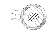
- FIG. 2 is a view of the fixing rod 1 shown in FIG. 1 in an XX cross section shown in the figure.
- the fixing rod 1 according to the embodiment of the present invention is configured to include a core member 2 and a reinforcing fiber layer 3 provided on the core member 2.
- the fixing rod 1 it is possible to provide a fixing rod having high rigidity and high durability due to a deformation load while reducing damage at the time of screw fixing. More specifically, because it adopts a solid double structure and uses a material with a large average flexural modulus for the outer layer as described later, it is a fixture with excellent bending rigidity and crushing strength of the entire rod. It becomes possible to provide a rod for use.
- the average flexural modulus refers to a value calculated by dividing the flexural rigidity of the entire corresponding portion by the secondary moment of the relevant portion.
- the fixing rod 1 is configured to include a coating layer provided on the reinforcing fiber layer 3.
- the coating layer can be formed of, for example, epoxy, phenol, unsaturated polyester, PA, PC, PPSU, POM, PP, PE, ABS, PS, PAEK or PEEK, but is not limited thereto.
- the core member 2 is made of a resin containing fibers.
- the fiber is any of carbon, glass, aramid, boron or SiC
- the resin is a thermosetting resin (for example, epoxy, phenol). , Unsaturated polyester, etc.), or a thermoplastic resin (eg, PA, PC, PPSU, POM, PP, PE, ABS, PS, PAEK, PEEK, etc.). In this way, it is possible to increase the bending rigidity and the strength of the core member.
- the reinforcing fiber layer 3 is a fiber reinforced resin, carbon, glass, boron, SiC or aramid is used as the fiber, and the thermosetting resin is used as the resin.
- the thermosetting resin is used as the resin.
- thermoplastic resin eg, PA, PC, PPSU, POM, PP, PE, ABS, PS, PAEK, PEEK, etc.
- the fibers of the reinforcing fiber layer 3 are configured to be long fibers. Since the fibers of the reinforcing fiber layer 3 are long fibers, it is possible to further increase the bending rigidity and the strength.
- the fiber content of the reinforcing fiber layer 3 is configured to be 60% by weight or more.
- the fiber layer in which the long fibers are emphasized at a high density makes it possible to form the fixing rod 1 having high rigidity and excellent durability.
- the fixing rod 1 according to the embodiment of the present invention includes a core member 2 and a reinforcing fiber layer 3 provided on the core member 2, and the reinforcing fiber layer 3 is a fiber. It is configured to include an axial length fiber layer 4 whose direction is oriented in the axial length direction (front-back direction of the paper surface) and an oblique fiber layer 5 whose fiber direction is oblique from the axial length direction.
- the axial length fiber layer 4 has advantages in terms of flexural rigidity and bending strength, and the oblique fiber layer 5 has advantages in terms of torsional rigidity and torsional strength, so that the core member 2 and the reinforcing fiber layer 3 have advantages. This makes it possible to provide a fixing rod having high rigidity and high durability due to a deformation load while reducing damage during screw fixing.
- the reinforcing fiber layer 3 includes a plurality of reinforcing fiber layers, and at least one layer has an oblique direction in which the fiber direction is inclined with respect to the axial length direction. It can be configured to be a fiber layer.
- the oblique fiber layer 5 has advantages in terms of torsional rigidity and torsional strength, the core member 2 and the reinforced fiber layer 3 reduce damage during screw fixing, and are deformed with high rigidity. It is possible to provide a fixing rod having high durability due to a load.
- the oblique fiber layer has a fiber angle in the range of 5 ° to 85 ° or ⁇ 5 ° to ⁇ 85 °.
- the most effective fiber angle of the oblique fiber layer is about ⁇ 45 °. The reason is that the shear modulus at ⁇ 45 ° is the maximum and the torsional rigidity is also the maximum.
- the fiber directions of the reinforcing fiber layers are aligned, and the thickness of the layers is, for example, in the range of 0.02 mm to 0.25 mm. .. In this way, the density of the resin is made uniform, and it is possible to reduce the variation in strength depending on the site.
- the reinforcing fiber layer includes a plurality of reinforcing fiber layers, it is used for at least one or more reinforcing fiber layers of the plurality of reinforcing fiber layers.
- the flexural modulus of the fiber is larger than the flexural modulus of the core member. In this way, by combining the reinforcing fiber layer with the core member while giving it a certain elasticity, it is possible to maintain high bending rigidity and crushing strength of the entire rod.
- the fixing rod 1 according to the embodiment of the present invention is configured to include a core member 2 and a reinforcing fiber layer 3 provided on the core member 2.
- the core member 2 is formed of PEEK / CF (short fibers) and has an outer shape of about 3.0 mm.
- the reinforcing fiber layer 3 is formed of a first laminated layer 6, a second laminated layer 7, and a third laminated layer 8.
- the first laminated layer 6 is formed by laminating a glass scrim on a UD.
- the UD has a fiber elastic modulus of 30 tons, a resin content of RC 24%, and a thickness of about 0.103 mm, and the scrim has a fiber elasticity.
- the modulus is 7 tons, the resin content is 28%, and the thickness is 0.012 mm.
- the second laminated layer 7 is obtained by laminating two diagonal layers, and the diagonal layer has a fiber elastic modulus of 30 tons, a resin content of RC 30%, and a thickness of about 0.051 mm.
- the tilt angle is configured to be + 45 ° or ⁇ 45 °.
- the third laminated layer 8 is formed by laminating a glass scrim on a UD.
- the UD has a fiber elastic modulus of 30 tons, a resin content of RC 24%, and a thickness of about 0.103 mm, and the scrim has a fiber elasticity.
- the modulus is 7 tons, the resin content is 28%, and the thickness is 0.012 mm.
- FIG. 5 is a view of the fixture rod 1 according to the embodiment of the present invention in which each layer is formed as shown in FIG. 4 in the XX cross section shown in FIG.
- the fixing rod 1 according to the embodiment of the present invention includes a core member 2 and a reinforcing fiber layer 3 provided on the core member 2, and the reinforcing fiber layer 3 is described above. It is formed by the first laminated layer 6, the second laminated layer 7, and the third laminated layer 8.
- the fixing rod 1 it is possible to provide a fixing rod having high rigidity and high durability due to a deformation load while reducing damage at the time of screw fixing. More specifically, because it adopts a solid double structure and uses a material with a large average flexural modulus for the outer layer as described later, it is a fixture with excellent bending rigidity and crushing strength of the entire rod. It becomes possible to provide a rod for use.
- the average flexural modulus refers to a value calculated by dividing the flexural rigidity of the entire corresponding portion by the secondary moment of the relevant portion.
- step 1 the prepreg is cut (cutting the prepreg). Then, as step 2, a core material (for example, carbon solid (long fiber)) is prepared. As a step 3, since the core material is not stiff, the V-groove rail shown in FIG. 6A is used, and a temporary fixing resin is applied to temporarily fix the core material (temporary fixing). As step 4, the prepreg is wound.
- a core material for example, carbon solid (long fiber)
- step 3 since the core material is not stiff, the V-groove rail shown in FIG. 6A is used, and a temporary fixing resin is applied to temporarily fix the core material (temporary fixing).
- step 4 the prepreg is wound.
- step 5 curing is performed using the grooved orthodontic mold shown in FIG. 6 (b).
- the reason for using the straightening die is that it may be slightly bent at the time of winding in step 4 described above, and it is necessary to correct this.
- cutting is performed in step 6, the tape is removed in step 7, and finally, centerless is performed in step 8 for adjusting the outer diameter.
- the fixing rod 1 that reduces damage during screw fixing, has high rigidity, and is highly durable due to a deformation load. It becomes possible to do. More specifically, because it adopts a solid double structure and uses a material with a large average flexural modulus for the outer layer as described later, it is a fixture with excellent bending rigidity and crushing strength of the entire rod. It becomes possible to provide a rod for use.
- the average flexural modulus refers to a value calculated by dividing the flexural rigidity of the entire corresponding portion by the secondary moment of the relevant portion.
- each component described herein is not limited to those expressly described in the embodiments, and each component may be included in the scope of the present invention. Can be modified to have the dimensions, materials, and arrangement of.
- components not explicitly described in the present specification may be added to the described embodiments, or some of the components described in each embodiment may be omitted.
Landscapes
- Health & Medical Sciences (AREA)
- Engineering & Computer Science (AREA)
- Orthopedic Medicine & Surgery (AREA)
- Life Sciences & Earth Sciences (AREA)
- Surgery (AREA)
- Heart & Thoracic Surgery (AREA)
- Animal Behavior & Ethology (AREA)
- General Health & Medical Sciences (AREA)
- Public Health (AREA)
- Veterinary Medicine (AREA)
- Chemical & Material Sciences (AREA)
- Neurology (AREA)
- Vascular Medicine (AREA)
- Epidemiology (AREA)
- Composite Materials (AREA)
- Materials Engineering (AREA)
- Mechanical Engineering (AREA)
- Biomedical Technology (AREA)
- Molecular Biology (AREA)
- Medical Informatics (AREA)
- Inorganic Chemistry (AREA)
- Nuclear Medicine, Radiotherapy & Molecular Imaging (AREA)
- General Engineering & Computer Science (AREA)
- Surgical Instruments (AREA)
- Cardiology (AREA)
- Oral & Maxillofacial Surgery (AREA)
- Transplantation (AREA)
- Laminated Bodies (AREA)
- Materials For Medical Uses (AREA)
- Prostheses (AREA)
Abstract
Description
本出願は、日本国特許出願2020-163964(2020年9月29日出願)に基づく優先権を主張し、その内容は参照により全体として本明細書に組み込まれる。
本発明は、脊椎を固定するための固定具に用いる固定具用ロッドに関する。
2 コア部材
3 強化繊維層
4 軸長繊維層
5 斜向繊維層
6 第1の積層層
7 第2の積層層
8 第3の積層層
10 脊椎用固定具
18 スクリュー部材
20 ロッド固定部材
21 凹部
22 押圧部材
Claims (11)
- 固定具用ロッドであって、
コア部材と、該コア部材上に設けられた強化繊維層とを含むことを特徴とする、固定具用ロッド。 - 前記強化繊維層上に設けられた被覆層を含む、請求項1に記載の固定具用ロッド。
- 前記コア部材は、繊維を含む樹脂で形成されている、請求項1又は2に記載の固定具用ロッド。
- 前記繊維は、カーボン、ガラス、アラミド、ボロン又はSiCのいずれかであり、前記樹脂は、エポキシ、フェノール、不飽和ポリエステル、PA、PC、PPSU、POM、PP、PE、ABS、PS、PAEK又はPEEKのいずれかである、請求項3に記載の固定具用ロッド。
- 前記強化繊維層は、繊維強化樹脂であり、繊維として、カーボン、ガラス、ボロン、SiC又はアラミドを用い、樹脂としてエポキシ、フェノール、不飽和ポリエステル、PA、PC、PPSU、POM、PP、PE、ABS、PS、PAEK又はPEEKを用いる、請求項1から4までのいずれか1項に記載の固定具用ロッド。
- 前記強化繊維層の繊維は長繊維である、請求項1から5までのいずれか1項に記載の固定具用ロッド。
- 前記強化繊維層の繊維含有率は、60重量%以上である、請求項1から6までのいずれか1項に記載の固定具用ロッド。
- 前記強化繊維層は、複数の強化繊維層を含み、少なくとも1層は繊維方向が、軸長方向に対して傾斜する斜向繊維層である、請求項1から7までのいずれか1項に記載の固定具用ロッド。
- 前記斜向繊維層は、その繊維角度が、5°から85°又は-5°から-85°の範囲の角度である、請求項8に記載の固定具用ロッド。
- 前記強化繊維層の繊維方向は引き揃えられており、該層の厚みは、0.02mmから0.25mmの範囲にある、請求項1から9までのいずれか1項に記載の固定具用ロッド。
- 前記強化繊維層が複数の強化繊維層を含む場合、該複数の強化繊維層の少なくとも1つ以上の強化繊維層に使用されている繊維の曲げ弾性率は、前記コア部材の曲げ弾性率よりも大きい、請求項1から10までのいずれか1項に記載の固定具用ロッド。
Priority Applications (4)
| Application Number | Priority Date | Filing Date | Title |
|---|---|---|---|
| KR1020237006589A KR102825578B1 (ko) | 2020-09-29 | 2021-09-10 | 척추 고정구용 로드 |
| US18/027,818 US12599411B2 (en) | 2020-09-29 | 2021-09-10 | Rod for spinal brace |
| CN202180053600.2A CN115996837A (zh) | 2020-09-29 | 2021-09-10 | 脊椎固定器用杆 |
| EP21875136.0A EP4223502B1 (en) | 2020-09-29 | 2021-09-10 | Rod for spinal brace |
Applications Claiming Priority (2)
| Application Number | Priority Date | Filing Date | Title |
|---|---|---|---|
| JP2020163964A JP7446965B2 (ja) | 2020-09-29 | 2020-09-29 | 脊椎固定具用ロッド |
| JP2020-163964 | 2020-09-29 |
Publications (1)
| Publication Number | Publication Date |
|---|---|
| WO2022070834A1 true WO2022070834A1 (ja) | 2022-04-07 |
Family
ID=80950393
Family Applications (1)
| Application Number | Title | Priority Date | Filing Date |
|---|---|---|---|
| PCT/JP2021/033268 Ceased WO2022070834A1 (ja) | 2020-09-29 | 2021-09-10 | 脊椎固定具用ロッド |
Country Status (6)
| Country | Link |
|---|---|
| US (1) | US12599411B2 (ja) |
| EP (1) | EP4223502B1 (ja) |
| JP (1) | JP7446965B2 (ja) |
| KR (1) | KR102825578B1 (ja) |
| CN (1) | CN115996837A (ja) |
| WO (1) | WO2022070834A1 (ja) |
Cited By (2)
| Publication number | Priority date | Publication date | Assignee | Title |
|---|---|---|---|---|
| WO2024204311A1 (ja) * | 2023-03-31 | 2024-10-03 | グローブライド株式会社 | 破断断片が離散し難い脊椎内固定器具用ロッド |
| DE102023126213A1 (de) * | 2023-09-27 | 2025-03-27 | SRH Wald-Klinikum Gera GmbH | Schraube zur Anordnung in einem Wirbelkörper einer Wirbelsäule |
Families Citing this family (1)
| Publication number | Priority date | Publication date | Assignee | Title |
|---|---|---|---|---|
| WO2025088550A1 (en) * | 2023-10-26 | 2025-05-01 | Warsaw Orthopedic, Inc. | Non-metallic spinal screw |
Citations (4)
| Publication number | Priority date | Publication date | Assignee | Title |
|---|---|---|---|---|
| US20080262548A1 (en) * | 2007-03-23 | 2008-10-23 | Coligne Ag | Elongated stabilization member and bone anchor useful in bone and especially spinal repair processes |
| JP2011508623A (ja) | 2007-12-19 | 2011-03-17 | デピュイ・スパイン・インコーポレイテッド | ポリマー椎弓根ロッド及び製造方法 |
| JP2015186641A (ja) * | 2009-01-16 | 2015-10-29 | カーボフィックス オーソピーディックス リミテッド | 複合材骨インプラント |
| JP2020137454A (ja) * | 2019-02-28 | 2020-09-03 | グローブライド株式会社 | 釣糸ガイド及びその製造方法 |
Family Cites Families (41)
| Publication number | Priority date | Publication date | Assignee | Title |
|---|---|---|---|---|
| JP2627833B2 (ja) | 1991-06-14 | 1997-07-09 | 横浜ゴム株式会社 | ゴム/ゴム接着複合体の製造方法 |
| GB2256615B (en) | 1991-06-12 | 1995-03-01 | Yokohama Rubber Co Ltd | Process for the production of a rubber/rubber bonded composite sheet structure |
| US5415661A (en) | 1993-03-24 | 1995-05-16 | University Of Miami | Implantable spinal assist device |
| US5556687A (en) * | 1994-10-14 | 1996-09-17 | Acromed Corporation | Composite structure suitable for use as a bone plate and method for making said structure |
| JPH11296033A (ja) | 1998-04-09 | 1999-10-29 | Ricoh Co Ltd | 画像保持支持体およびその再生方法 |
| JP3593262B2 (ja) | 1998-06-10 | 2004-11-24 | 尚義 菅 | 脊椎固定具 |
| FR2812186B1 (fr) | 2000-07-25 | 2003-02-28 | Spine Next Sa | Piece de liaison souple pour la stabilisation du rachis |
| ES2223764T3 (es) | 2001-03-09 | 2005-03-01 | Co-Ligne Ag | Implante longitudinal. |
| WO2004096066A2 (en) | 2003-04-25 | 2004-11-11 | Kitchen Michael S | Spinal curvature correction device |
| WO2006044315A2 (en) * | 2004-10-13 | 2006-04-27 | Fulcrum Composites, Inc. | Composite article |
| US20060247638A1 (en) | 2005-04-29 | 2006-11-02 | Sdgi Holdings, Inc. | Composite spinal fixation systems |
| US20060276788A1 (en) | 2005-05-26 | 2006-12-07 | Amedica Corporation | Osteoconductive spinal fixation system |
| US20070233064A1 (en) * | 2006-02-17 | 2007-10-04 | Holt Development L.L.C. | Apparatus and method for flexible spinal fixation |
| US20070233073A1 (en) | 2006-03-02 | 2007-10-04 | Sdgi Holdings, Inc. | Spinal rod characterized by a time-varying stiffness |
| US8475498B2 (en) | 2007-01-18 | 2013-07-02 | Roger P. Jackson | Dynamic stabilization connecting member with cord connection |
| US8057516B2 (en) | 2007-03-21 | 2011-11-15 | Zimmer Spine, Inc. | Spinal stabilization system with rigid and flexible elements |
| US20090005873A1 (en) | 2007-06-29 | 2009-01-01 | Michael Andrew Slivka | Spinous Process Spacer Hammock |
| US20090018583A1 (en) | 2007-07-12 | 2009-01-15 | Vermillion Technologies, Llc | Dynamic spinal stabilization system incorporating a wire rope |
| US20090093819A1 (en) | 2007-10-05 | 2009-04-09 | Abhijeet Joshi | Anisotropic spinal stabilization rod |
| US8043339B2 (en) | 2007-10-24 | 2011-10-25 | Zimmer Spine, Inc. | Flexible member for use in a spinal column and method for making |
| US8100971B2 (en) * | 2007-11-05 | 2012-01-24 | Warsaw Orthopedic, Inc. | Coatings for spinal implants |
| DE602008004213D1 (de) | 2008-05-06 | 2011-02-10 | Biedermann Motech Gmbh | Stangenförmiges Implantat, insbesondere zur dynamischen Stabilisierung der Wirbelsäule |
| JP5608642B2 (ja) | 2008-05-13 | 2014-10-15 | ストライカー・スピン | 複合脊椎ロッド |
| US9408649B2 (en) | 2008-09-11 | 2016-08-09 | Innovasis, Inc. | Radiolucent screw with radiopaque marker |
| US9055979B2 (en) | 2008-12-03 | 2015-06-16 | Zimmer Gmbh | Cord for vertebral fixation having multiple stiffness phases |
| US9433439B2 (en) * | 2009-09-10 | 2016-09-06 | Innovasis, Inc. | Radiolucent stabilizing rod with radiopaque marker |
| US9011494B2 (en) | 2009-09-24 | 2015-04-21 | Warsaw Orthopedic, Inc. | Composite vertebral rod system and methods of use |
| WO2011042998A1 (ja) | 2009-10-06 | 2011-04-14 | 横浜ゴム株式会社 | ゴム積層体 |
| US20110106162A1 (en) | 2009-10-30 | 2011-05-05 | Warsaw Orthopedic, Inc. | Composite Connecting Elements for Spinal Stabilization Systems |
| US20110152937A1 (en) | 2009-12-22 | 2011-06-23 | Warsaw Orthopedic, Inc. | Surgical Implants for Selectively Controlling Spinal Motion Segments |
| JP5584898B2 (ja) | 2010-06-10 | 2014-09-10 | 昭和医科工業株式会社 | 疲労強度に優れた低弾性率の脊椎固定用チタン合金製ロッドの製造方法 |
| US20120029564A1 (en) * | 2010-07-29 | 2012-02-02 | Warsaw Orthopedic, Inc. | Composite Rod for Spinal Implant Systems With Higher Modulus Core and Lower Modulus Polymeric Sleeve |
| JP2013540468A (ja) | 2010-09-08 | 2013-11-07 | ロジャー・ピー・ジャクソン | 弾性部および非弾性部を有する動的固定化部材 |
| US9090029B2 (en) * | 2012-02-06 | 2015-07-28 | Warsaw Orthopedic, Inc. | Pultrusion process for preparing composites having low percentage of fibers and articles made from same |
| DE102013013024A1 (de) | 2012-08-03 | 2014-02-06 | Orthobion Gmbh | Verfahren zum Herrstellen eines Pedikelstabs, Pedikelstab für ein System zur Fixierung und Stabilisierung einer Wirbelsäule und zugehöriges System |
| PT2982504T (pt) | 2013-04-02 | 2019-07-10 | Toray Industries | Laminado sanduíche, estrutura sanduíche e produto moldado unificado com a utilização dos mesmos e processos para produção de ambos |
| US9408636B2 (en) | 2014-01-27 | 2016-08-09 | Luke Lu | Bone connection material |
| GB201403032D0 (en) * | 2014-02-20 | 2014-04-09 | Invibio Ltd | Medical device |
| EP3203941B1 (en) | 2014-10-09 | 2020-09-09 | Pedoulias, Panagiotis | Bone scaffold improvements |
| EP3236866B1 (en) | 2014-12-26 | 2019-11-13 | Ossio Ltd | Continuous-fiber reinforced biocomposite medical implants |
| JP7432538B2 (ja) | 2021-01-05 | 2024-02-16 | グローブライド株式会社 | 脊椎固定具用ロッド及びこれを備える脊椎用固定具 |
-
2020
- 2020-09-29 JP JP2020163964A patent/JP7446965B2/ja active Active
-
2021
- 2021-09-10 EP EP21875136.0A patent/EP4223502B1/en active Active
- 2021-09-10 KR KR1020237006589A patent/KR102825578B1/ko active Active
- 2021-09-10 WO PCT/JP2021/033268 patent/WO2022070834A1/ja not_active Ceased
- 2021-09-10 US US18/027,818 patent/US12599411B2/en active Active
- 2021-09-10 CN CN202180053600.2A patent/CN115996837A/zh active Pending
Patent Citations (4)
| Publication number | Priority date | Publication date | Assignee | Title |
|---|---|---|---|---|
| US20080262548A1 (en) * | 2007-03-23 | 2008-10-23 | Coligne Ag | Elongated stabilization member and bone anchor useful in bone and especially spinal repair processes |
| JP2011508623A (ja) | 2007-12-19 | 2011-03-17 | デピュイ・スパイン・インコーポレイテッド | ポリマー椎弓根ロッド及び製造方法 |
| JP2015186641A (ja) * | 2009-01-16 | 2015-10-29 | カーボフィックス オーソピーディックス リミテッド | 複合材骨インプラント |
| JP2020137454A (ja) * | 2019-02-28 | 2020-09-03 | グローブライド株式会社 | 釣糸ガイド及びその製造方法 |
Non-Patent Citations (1)
| Title |
|---|
| See also references of EP4223502A4 |
Cited By (4)
| Publication number | Priority date | Publication date | Assignee | Title |
|---|---|---|---|---|
| WO2024204311A1 (ja) * | 2023-03-31 | 2024-10-03 | グローブライド株式会社 | 破断断片が離散し難い脊椎内固定器具用ロッド |
| JP2024145952A (ja) * | 2023-03-31 | 2024-10-15 | グローブライド株式会社 | 破断断片が離散し難い脊椎内固定器具用ロッド |
| DE102023126213A1 (de) * | 2023-09-27 | 2025-03-27 | SRH Wald-Klinikum Gera GmbH | Schraube zur Anordnung in einem Wirbelkörper einer Wirbelsäule |
| DE102023126213B4 (de) * | 2023-09-27 | 2025-04-30 | SRH Wald-Klinikum Gera GmbH | Schraube zur Anordnung in einem Wirbelkörper einer Wirbelsäule |
Also Published As
| Publication number | Publication date |
|---|---|
| KR102825578B1 (ko) | 2025-06-27 |
| EP4223502A4 (en) | 2024-05-29 |
| US20230329756A1 (en) | 2023-10-19 |
| EP4223502A1 (en) | 2023-08-09 |
| JP2022056131A (ja) | 2022-04-08 |
| EP4223502B1 (en) | 2026-04-22 |
| KR20230042111A (ko) | 2023-03-27 |
| CN115996837A (zh) | 2023-04-21 |
| US12599411B2 (en) | 2026-04-14 |
| JP7446965B2 (ja) | 2024-03-11 |
Similar Documents
| Publication | Publication Date | Title |
|---|---|---|
| WO2022070834A1 (ja) | 脊椎固定具用ロッド | |
| JP7829751B2 (ja) | 脊椎固定具用ロッド | |
| JP6832338B2 (ja) | コイルばね | |
| KR102924801B1 (ko) | 척추 고정구용 로드 및 이것을 구비하는 척추용 고정구 | |
| US5916682A (en) | Carbon fiber reinforced composite material | |
| JP2000245880A (ja) | ゴルフクラブシャフト | |
| JP6490413B2 (ja) | 繊維強化複合材料製シャフト | |
| WO2022158058A1 (ja) | 脊椎固定具用ロッド及びこれを備える脊椎用固定具 | |
| JP6312491B2 (ja) | ウェブ製造用ロール | |
| JPH0792396A (ja) | Cfrp製光学用筒 | |
| EP4691503A1 (en) | Intraspinal fixation instrument rod | |
| WO2024204311A1 (ja) | 破断断片が離散し難い脊椎内固定器具用ロッド | |
| JPH09164600A (ja) | テーパ付き中空シャフト | |
| JP2021094739A (ja) | 筒状体 | |
| JP2024119267A (ja) | ゴルフクラブシャフト | |
| JP2022159458A (ja) | 釣糸ガイド、該ガイドを備える釣竿及び釣糸ガイドの成型方法 | |
| TW202613375A (zh) | 纖維束強化結構 | |
| JPH03203611A (ja) | 繊維強化樹脂管状体およびその成形用プリプレグ |
Legal Events
| Date | Code | Title | Description |
|---|---|---|---|
| 121 | Ep: the epo has been informed by wipo that ep was designated in this application |
Ref document number: 21875136 Country of ref document: EP Kind code of ref document: A1 |
|
| ENP | Entry into the national phase |
Ref document number: 20237006589 Country of ref document: KR Kind code of ref document: A |
|
| WWE | Wipo information: entry into national phase |
Ref document number: KR1020237006589 Country of ref document: KR |
|
| NENP | Non-entry into the national phase |
Ref country code: DE |
|
| ENP | Entry into the national phase |
Ref document number: 2021875136 Country of ref document: EP Effective date: 20230502 |
|
| WWG | Wipo information: grant in national office |
Ref document number: 1020237006589 Country of ref document: KR |
|
| WWG | Wipo information: grant in national office |
Ref document number: 18027818 Country of ref document: US |
|
| WWG | Wipo information: grant in national office |
Ref document number: 2021875136 Country of ref document: EP |