WO2022070982A1 - 内視鏡 - Google Patents
内視鏡 Download PDFInfo
- Publication number
- WO2022070982A1 WO2022070982A1 PCT/JP2021/034268 JP2021034268W WO2022070982A1 WO 2022070982 A1 WO2022070982 A1 WO 2022070982A1 JP 2021034268 W JP2021034268 W JP 2021034268W WO 2022070982 A1 WO2022070982 A1 WO 2022070982A1
- Authority
- WO
- WIPO (PCT)
- Prior art keywords
- liquid
- communication hole
- gas
- recess
- air
- Prior art date
- Legal status (The legal status is an assumption and is not a legal conclusion. Google has not performed a legal analysis and makes no representation as to the accuracy of the status listed.)
- Ceased
Links
Images


Classifications
-
- A—HUMAN NECESSITIES
- A61—MEDICAL OR VETERINARY SCIENCE; HYGIENE
- A61B—DIAGNOSIS; SURGERY; IDENTIFICATION
- A61B1/00—Instruments for performing medical examinations of the interior of cavities or tubes of the body by visual or photographical inspection, e.g. endoscopes; Illuminating arrangements therefor
- A61B1/012—Instruments for performing medical examinations of the interior of cavities or tubes of the body by visual or photographical inspection, e.g. endoscopes; Illuminating arrangements therefor characterised by internal passages or accessories therefor
- A61B1/015—Control of fluid supply or evacuation
-
- A—HUMAN NECESSITIES
- A61—MEDICAL OR VETERINARY SCIENCE; HYGIENE
- A61B—DIAGNOSIS; SURGERY; IDENTIFICATION
- A61B1/00—Instruments for performing medical examinations of the interior of cavities or tubes of the body by visual or photographical inspection, e.g. endoscopes; Illuminating arrangements therefor
- A61B1/00064—Constructional details of the endoscope body
- A61B1/00071—Insertion part of the endoscope body
- A61B1/0008—Insertion part of the endoscope body characterised by distal tip features
- A61B1/00091—Nozzles
-
- A—HUMAN NECESSITIES
- A61—MEDICAL OR VETERINARY SCIENCE; HYGIENE
- A61B—DIAGNOSIS; SURGERY; IDENTIFICATION
- A61B1/00—Instruments for performing medical examinations of the interior of cavities or tubes of the body by visual or photographical inspection, e.g. endoscopes; Illuminating arrangements therefor
- A61B1/00112—Connection or coupling means
- A61B1/00119—Tubes or pipes in or with an endoscope
-
- A—HUMAN NECESSITIES
- A61—MEDICAL OR VETERINARY SCIENCE; HYGIENE
- A61B—DIAGNOSIS; SURGERY; IDENTIFICATION
- A61B1/00—Instruments for performing medical examinations of the interior of cavities or tubes of the body by visual or photographical inspection, e.g. endoscopes; Illuminating arrangements therefor
- A61B1/00112—Connection or coupling means
- A61B1/00121—Connectors, fasteners and adapters, e.g. on the endoscope handle
- A61B1/00128—Connectors, fasteners and adapters, e.g. on the endoscope handle mechanical, e.g. for tubes or pipes
-
- A—HUMAN NECESSITIES
- A61—MEDICAL OR VETERINARY SCIENCE; HYGIENE
- A61B—DIAGNOSIS; SURGERY; IDENTIFICATION
- A61B1/00—Instruments for performing medical examinations of the interior of cavities or tubes of the body by visual or photographical inspection, e.g. endoscopes; Illuminating arrangements therefor
- A61B1/12—Instruments for performing medical examinations of the interior of cavities or tubes of the body by visual or photographical inspection, e.g. endoscopes; Illuminating arrangements therefor with cooling or rinsing arrangements
- A61B1/126—Instruments for performing medical examinations of the interior of cavities or tubes of the body by visual or photographical inspection, e.g. endoscopes; Illuminating arrangements therefor with cooling or rinsing arrangements provided with means for cleaning in-use
Definitions
- the present invention relates to an endoscope in which a confluence recess where a liquid and a gas merge is formed at a tip portion.
- an endoscope having a gas passage and a liquid passage and having the tips of the gas passage and the liquid passage communicating with each other at the tip of an insertion portion inserted into a body cavity has become widespread.
- Patent Document 1 describes the size of the opening of the air supply pipe in the communication portion between the air supply pipe (gas passage) and the water supply passage pipe (liquid passage), and the opening of a nozzle for injecting air or water.
- an endoscope capable of preventing water from flowing back to the air supply channel side during a water supply operation and suppressing water droplets from being ejected together with air during a subsequent air supply operation by making the size smaller than the size of the above.
- the present invention has been made in view of such circumstances, and an object of the present invention is to provide an endoscope capable of preventing the liquid in the liquid passage from being sucked up and ejected together with the gas during the air supply operation. To provide.
- the endoscope according to the present invention is an endoscope having a liquid path through which a liquid passes and a gas path through which a gas passes, and a confluence recess in which the liquid and the gas merge is formed at the tip thereof.
- One end side and one end side of the gas passage communicate with the confluence recess, and the size of the first communication hole between the gas passage and the confluence recess is the size of the second communication hole between the liquid passage and the confluence recess. Is larger than the size of.
- the size of the first communication hole between the gas passage and the merging recess is larger than the size of the second communication hole between the liquid passage and the merging recess, so that only the gas is removed from the nozzle.
- the injecting air supply operation it is possible to suppress an increase in the air velocity in the vicinity of the first communication hole and prevent the liquid in the liquid passage from being sucked up.
- the present invention it is possible to prevent the liquid in the liquid passage from being sucked up and sprayed together with the gas during the air supply operation.
- Embodiment 1 of this invention It is an external view of the endoscope which concerns on Embodiment 1 of this invention. It is a schematic diagram which shows the tip surface of the tip part of an endoscope. It is a partial cross-sectional view explaining the structure of the tip part. It is an enlarged view which shows the part of the confluence concave part of FIG. 3 enlarged. It is sectional drawing by VV line of FIG. FIG. 4 is a cross-sectional view taken along the line VI-VI of FIG. It is explanatory drawing explaining the communication state of a confluence concave part and an air supply connection part. This is a simulation result showing the air flow when the sizes of the first communication hole and the second communication hole are the same and when the size of the first communication hole is larger than that of the second communication hole.
- FIG. 5 is an enlarged view showing an enlarged portion of a confluence recess of the endoscope according to the second embodiment.
- FIG. 3 is an enlarged view showing an enlarged portion of a confluence recess of the endoscope according to the third embodiment.
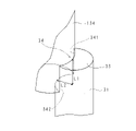
- FIG. 1 is an external view of the endoscope 10 according to the first embodiment of the present invention.
- the endoscope 10 of the present embodiment has an imaging means, an insertion unit 14 to be inserted into the body cavity of a subject, an operation unit 20 for operating the insertion unit 14, a processor (not shown), a light source device, and a feeding unit. It is provided with a connector portion 24 connected to an air supply device or the like.
- the insertion unit 14 is connected to the operation unit 20 via the folding unit 16, and the operation unit 20 is connected to the connector unit 24 via the universal cord 25.
- the universal cord 25 has flexibility, and is an electric wire that sends an electric signal from the image pickup means of the insertion portion 14 to the connector portion 24, a water channel through which water sent from the connector portion 24 passes, and an air passage through which air passes. And include.
- the operation unit 20 has a grip portion 205, a button 201 for receiving an instruction such as water supply or air supply from the user, and a bending knob 21 for operating the bending of the bending portion 12, which will be described later.
- the grip portion 205 has a substantially cylindrical shape, and the diameter is reduced toward the insertion portion 14.
- the grip portion 205 is provided with a channel inlet 22 for inserting a treatment tool or the like near the insertion portion 14.
- the insertion portion 14 has a small diameter cylindrical shape and is configured to be bendable. It has a tip portion 13, a curved portion 12, and a soft portion 11 in order from one end on the tip side.
- the curved portion 12 is curved according to the operation of the curved knob 21.
- the tip portion 13 has a cylindrical shape, and houses an imaging unit (not shown) including an imaging means such as a CCD (Charge Coupled Device) and a CMOS (Complementary Metal Oxide Semiconductor), an observation optical system, and the like. ..
- an imaging unit including an imaging means such as a CCD (Charge Coupled Device) and a CMOS (Complementary Metal Oxide Semiconductor), an observation optical system, and the like. ..
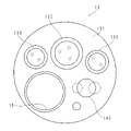
- FIG. 2 is a schematic view showing the tip surface 131 of the tip portion 13 of the endoscope 10.
- the tip surface 131 of the tip portion 13 has a circular shape.
- the tip portion 13 is provided with an observation optical system 132, an air supply / water supply nozzle 140, a channel outlet 18, an illumination optical system 133, and the like.
- Two illumination optical systems 133 are provided on the tip surface 131 so as to be separated from each other, and the observation optical system 132 is provided between the two illumination optical systems 133. Further, on the tip surface 131, an air supply / water supply nozzle 140 and a channel outlet 18 are provided at a distance from the observation optical system 132. The air supply / water supply nozzle 140 injects air or water toward the observation optical system 132, and the illumination optical system 133 emits irradiation light to illuminate the subject.
- FIG. 3 is a partial cross-sectional view illustrating the configuration of the tip portion 13.
- a confluence recess 134 in which air and water sent from the operation unit 20 merge is formed on the tip surface 131 of the tip portion 13, and a part of the air supply / water supply nozzle 140 is engaged with the confluence recess 134. ..
- the merging recess 134 has a circular cross-sectional view and extends in the axial length direction of the tip portion 13. One end of the merging recess 134 near the tip surface 131 in the longitudinal direction is engaged with the air supply / water supply nozzle 140. Further, the other end side of the merging recess 134 communicates with the gas passage 30 and the liquid passage 40, which will be described later.
- the air supply / water supply nozzle 140 has a tubular portion 143 having a circular cross-sectional view and a lid portion 142 that covers the opening end on one end side of the tubular portion 143.
- the lid portion 142 and the tubular portion 143 are integrally formed.
- the tubular portion 143 has an outer diameter slightly smaller than the inner diameter of the merging recess 134, and most of the tubular portion 143 is internally fitted in the merging recess 134.
- the lid portion 142 has a disk shape and has a diameter larger than the outer diameter of the tubular portion 143. Only the lid portion 142 is exposed to the tip surface 131 in a state where the air supply / water supply nozzle 140 is engaged with the confluence recess 134.
- the air supply / water supply nozzle 140 has an outlet 141 from which air or water is emitted.
- the outlet 141 has a substantially oval shape and is open toward the observation optical system 132.
- the exit port 141 is provided on the lid portion 142 side of the tubular portion 143.
- the other end of the merging recess 134 communicates with the gas passage 30 and the liquid passage 40.
- the gas passage 30 supplies the gas (for example, air) sent from the air supply / water supply device to the air supply / water supply nozzle 140.
- the liquid passage 40 supplies the liquid (for example, water) sent from the air supply / water supply device to the air supply / water supply nozzle 140.
- the gas passage 30 includes an air supply tube 32 and an air supply connecting portion 31.
- the air supply tube 32 communicates with the other end side of the merging recess 134 via the air supply connecting portion 31. Further, the air supply tube 32 penetrates the insertion portion 14 in the longitudinal direction and is provided so as to straddle the curved portion 12 and the tip portion 13. That is, one end of the air supply tube 32 is connected to the air supply connecting portion 31, and the other end of the air supply tube 32 is connected to the air supply water supply device via the operation unit 20 and the connector unit 24.
- the liquid passage 40 includes a water supply tube 42 and a water supply connecting portion 41.
- the water supply tube 42 communicates with the other end side of the merging recess 134 via the water supply connecting portion 41. Further, the water supply tube 42 penetrates the insertion portion 14 in the longitudinal direction and is provided so as to straddle the curved portion 12 and the tip portion 13. That is, one end of the water supply tube 42 is connected to the water supply connecting portion 41, and the other end of the water supply tube 42 is connected to the air supply water supply device via the operation portion 20 and the connector portion 24.
- FIG. 4 is an enlarged view showing an enlarged portion of the confluence recess 134 in FIG. 3
- FIG. 5 is a cross-sectional view taken along the line VV of FIG. 4
- FIG. 6 is a line VI-VI of FIG.
- FIG. 7 is an explanatory view illustrating a communication state of the merging recess 134 and the air supply connecting portion 31. In FIG. 7, the contours of the confluence recess 134 and the air supply connecting portion 31 are shown.
- the air supply connecting portion 31 has a substantially cylindrical shape, and sends the air flowing from the air supply tube 32 to the confluence recess 134.
- the air supply connecting portion 31 has a diameter equal to the inner diameter of the air supply tube 32, and the upstream end is connected to the air supply tube 32.
- a gas guide wall 33 for guiding air to the confluence recess 134 is formed at the downstream end.
- the gas guide wall 33 is formed so as to be orthogonal to the axial length direction of the air supply connecting portion 31.
- a first communication hole 34 is formed in the communication portion of the air supply communication portion 31 and the confluence recess 134.
- the first communication hole 34 has a dimension L1 in the axial length direction of the air supply connecting portion 31 longer than a dimension L2 in the direction intersecting the axial length direction of the air supply connecting portion 31.
- the first communication hole 34 has an orthogonal opening 341 (see FIGS. 5 and 7) that opens in a direction orthogonal to the axial length direction of the air supply connection portion 31 and a shaft of the air supply connection portion 31. It includes a parallel opening 342 (see FIGS. 6 and 7) that opens in a direction parallel to the longitudinal direction.
- the orthogonal opening 341 is wider than the parallel opening 342. That is, as described above, the first communication hole 34 has a dimension L1 longer than the dimension L2, so that the orthogonal opening 341 is wider than the parallel opening 342.
- the orthogonal opening 341 is a region that looks like a rectangle in FIG. 5, and the parallel opening 342 is a region that looks like a substantially convex lens in FIG. 6 (see the thick line in FIG. 6).
- the water supply connecting portion 41 has a substantially cylindrical shape, and sends the water flowing from the water supply tube 42 to the confluence recess 134.
- the water supply connecting portion 41 has a diameter equal to the inner diameter of the water supply tube 42, and the upstream end is connected to the water supply tube 42.
- a liquid guide wall 43 for guiding water from the water supply tube 42 into the confluence recess 134 is formed at the downstream end.
- the liquid guide wall 43 is formed so as to be orthogonal to the axial length direction of the water supply connecting portion 41.
- a second communication hole 44 is formed in the communication portion of the water supply communication connection portion 41 and the confluence recess 134. That is, like the first communication hole 34, the second communication hole 44 has an orthogonal opening (not shown) that opens in a direction orthogonal to the axial length direction of the water supply connection portion 41 and a water supply connection portion 41. Includes a parallel opening 442 (see FIG. 6) that opens in a direction parallel to the axial length direction of the. Similar to the first communication hole 34, the orthogonal opening of the second communication hole 44 is a substantially rectangular region, and the parallel opening 442 is a substantially convex lens-shaped region (see the thick line in FIG. 6).
- the second communication hole 44 has a dimension L3 in the axial length direction of the water supply connecting portion 41 longer than the dimension L4 in the direction intersecting the axial length direction of the water supply connecting portion 41.
- the dimension of the water supply connecting portion 41 in the axial length direction is shorter than the dimension of the air supply connecting portion 31 in the axial length direction (see FIG. 4).
- the dimension L3 of the second communication hole 44 is shorter than the dimension L1 of the first communication hole 34 (see FIG. 4), and the dimension L4 of the second communication hole 44 is substantially equal to the dimension L2 of the first communication hole 34. (See FIGS. 4 and 6).
- the air sent from the folding portion 16 side through the air supply tube 32 flows into the confluence recess 134 via the air supply connecting portion 31, and the water sent through the water feeding tube 42 is connected to the water supply. It flows into the merging recess 134 through the portion 41. After that, the air and water flow into the air supply / water supply nozzle 140 and are emitted toward the observation optical system 132 through the exit port 141.
- the dimension L4 of the second communication hole 44 is substantially equal to the dimension L2 of the first communication hole 34, but the dimension L3 of the second communication hole 44. Is shorter than the dimension L1 of the first communication hole 34. That is, the size of the first communication hole 34 is larger than the size of the second communication hole 44.
- the first communication hole 34 and the second communication hole 44 have the same size, it is possible to suppress an increase in the air flow velocity in the vicinity of the first communication hole 34, and the air flow becomes smoother.
- the generation of vortices in the vicinity of the first communication hole 34 can be suppressed. Therefore, it is possible to suppress a decrease in air pressure in the vicinity of the first communication hole 34, that is, at the P1 position.
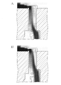
- FIG. 8 shows the air flow when the first communication hole 34 and the second communication hole 44 have the same size and when the size of the first communication hole 34 is larger than that of the second communication hole 44. It is a simulation result. That is, FIG. 8A shows a conventional endoscope, and FIG. 8B shows the endoscope 10 of the first embodiment.
- the direction of the arrow indicates the flow direction of air
- the length of the arrow indicates the velocity of air
- the light and dark also indicate the velocity of air.
- the length of the arrow at the P1 position (the part ⁇ in FIG. 8) is shorter in FIG. 8B than in FIG. 8A. That is, the velocity of air at the P1 position is suppressed in FIG. 8B as compared with that in FIG. 8A.
- the velocity of the air at the P1 position on the other end side of the merging recess 134 is suppressed, the air pressure at the P1 position, and the vicinity of the residual water surface in the water supply connecting portion 41. It is possible to suppress the occurrence of a difference from the air pressure at the P2 position of. Therefore, in the case of the air supply operation in which only air is ejected from the outlet 141, it is possible to prevent the problem that some water is ejected together with the air.
- the first communication hole 34 has a dimension L1 longer than the dimension L2 and an orthogonal opening 341 wider than the parallel opening 342. Therefore, the proportion of air flowing into the merging recess 134 through the orthogonal opening 341 is higher than the proportion of air flowing into the merging recess 134 through the parallel opening 342.
- the high-speed portion that is, the dense portion in the air flow is shifted farther from the second communication hole 44 than in FIG. 8A. That is, in the endoscope 10 of the first embodiment, by shifting the portion where the air flow is high to a distance from the second communication hole 44, a synergistic effect is brought about in suppressing the decrease in air pressure at the P1 position. There is.
- FIG. 9 is an enlarged view showing a portion of the confluence recess 134 of the endoscope 10 according to the second embodiment in an enlarged manner.
- the air supply connecting portion 31 has a substantially cylindrical shape, and the upstream end is connected to the air supply tube 32. Further, in the air supply connecting portion 31, a gas guide wall 33A for guiding air to the confluence recess 134 is formed at the downstream end.
- the gas guide wall 33A is formed diagonally with respect to the axial length direction of the air supply connecting portion 31, and the radial dimension of the air supply connecting portion 31 becomes shorter toward the downstream side of the air supply connecting portion 31. There is.
- a first communication hole 34 is formed in the communication portion of the air supply communication portion 31 and the confluence recess 134. Similar to the first embodiment, the first communication hole 34 has an orthogonal opening 341 (see FIGS. 5 and 7) that opens in a direction orthogonal to the axial length direction of the air supply connection portion 31 and air supply. It includes a parallel opening 342 (see FIGS. 6 and 7) that opens in a direction parallel to the axial length direction of the connecting portion 31, and the orthogonal opening 341 is wider than the parallel opening 342.
- the water supply connecting portion 41 has a substantially cylindrical shape, and the upstream end is connected to the water supply tube 42. Further, in the water supply connecting portion 41, a liquid guide wall 43 for guiding water to the confluence recess 134 is formed at the downstream end. The liquid guide wall 43 is formed so as to be orthogonal to the axial length direction of the water supply connecting portion 41.
- a second communication hole 44 is formed in the communication portion of the water supply communication connection portion 41 and the confluence recess 134. Similar to the first embodiment, the second communication hole 44 has an orthogonal opening (not shown) that opens in a direction orthogonal to the axial length direction of the water supply connection portion 41 and a shaft of the water supply connection portion 41. It includes a parallel opening 442 (see FIG. 6) that is open in a direction parallel to the longitudinal direction.
- the gas guide wall 33A that guides the air from the air supply tube 32 into the confluence recess 134 is oblique with respect to the axial length direction of the air supply connecting portion 31.
- the liquid guide wall 43 is formed so as to be orthogonal to the axial length direction of the water supply connecting portion 41.
- the air flows smoothly without suddenly changing its direction. Therefore, the generation of vortices can be suppressed, and the high-speed portion of the air flow in the vicinity of the first communication hole 34 can be shifted to the vicinity of the first communication hole 34, which is farther from the second communication hole 44. As a result, the air flow is reduced at the P1 position (see FIG. 4), so that it is possible to suppress the occurrence of a difference in air pressure between the P1 position and the P2 position. Can be prevented from the problem of being sprayed.
- the distance between the gas guide wall 33A and the liquid guide wall 43 is such that the gas guide wall 33A is orthogonal to the axial length direction of the air supply connecting portion 31. It is longer than the distance between the gas guide wall 33A and the liquid guide wall 43 (see the arrow in the broken line in FIG. 9) when the gas guide wall 33A and the liquid guide wall 43 are provided. Therefore, in the vicinity of the first communication hole 34, the high-speed portion of the air flow becomes far from the water supply communication connection portion 41, and the residual water in the water supply communication connection portion 41 is less likely to be affected by the above-mentioned difference in air pressure.
- FIG. 10 is an enlarged view showing a portion of the confluence recess 134 of the endoscope 10 according to the third embodiment in an enlarged manner.
- the air supply connecting portion 31 has a substantially cylindrical shape, and the upstream end is connected to the air supply tube 32. Further, in the air supply connecting portion 31, a gas guide wall 33A for guiding air to the confluence recess 134 is formed at the downstream end.
- the gas guide wall 33A is formed obliquely with respect to the axial length direction of the air supply connecting portion 31.
- a first communication hole 34 is formed in the communication portion of the air supply communication portion 31 and the confluence recess 134.
- the shape of the first communication hole 34 is the same as that of the first embodiment, and detailed description thereof will be omitted.
- the water supply connecting portion 41 has a substantially cylindrical shape, and the upstream end is connected to the water supply tube 42. Further, in the water supply connecting portion 41, a liquid guide wall 43 for guiding water to the confluence recess 134 is formed at the downstream end. The liquid guide wall 43 is formed so as to be orthogonal to the axial length direction of the water supply connecting portion 41.
- the water supply connecting portion 41 has a reduced diameter portion 41A formed in the intermediate portion in the axial length direction in which the diameter gradually decreases toward the downstream side, and the reduced diameter portion 41A on the upstream side of the reduced diameter portion 41A.
- the diameter is larger than the downstream side of 41A.
- a second communication hole 44 is formed in the communication portion of the water supply communication connection portion 41 and the confluence recess 134.
- the shape of the second communication hole 44 is the same as that of the first embodiment, and detailed description thereof will be omitted.
- the reduced diameter portion 41A is formed in the water supply connecting portion 41, and the diameter on the downstream side of the reduced diameter portion 41A is smaller than that on the upstream side. That is, since the diameter on the downstream side of the water supply connecting portion 41 is small, the surface tension of the residual water in the water feeding connecting portion 41 increases, and the residual water in the water feeding connecting portion 41 is in the P1 position and the P2 position (see FIG. 4). ) Is not easily affected by the difference in air pressure generated between them. Therefore, even if a difference in air pressure occurs between the P1 position and the P2 position, the suction of residual water in the water supply connecting portion 41 is suppressed.
- the liquid guide wall 43 is formed so as to be orthogonal to the axial length direction of the water supply connecting portion 41 has been described as an example, but the present invention is not limited to this.
- the liquid guide wall 43 may be formed obliquely with respect to the axial length direction of the water supply connecting portion 41, similarly to the gas guide wall 33A.
Landscapes
- Health & Medical Sciences (AREA)
- Life Sciences & Earth Sciences (AREA)
- Surgery (AREA)
- Engineering & Computer Science (AREA)
- Biomedical Technology (AREA)
- Molecular Biology (AREA)
- Pathology (AREA)
- Radiology & Medical Imaging (AREA)
- Nuclear Medicine, Radiotherapy & Molecular Imaging (AREA)
- Biophysics (AREA)
- Physics & Mathematics (AREA)
- Heart & Thoracic Surgery (AREA)
- Medical Informatics (AREA)
- Optics & Photonics (AREA)
- Animal Behavior & Ethology (AREA)
- General Health & Medical Sciences (AREA)
- Public Health (AREA)
- Veterinary Medicine (AREA)
- Mechanical Engineering (AREA)
- Instruments For Viewing The Inside Of Hollow Bodies (AREA)
- Endoscopes (AREA)
Abstract
Description
本出願は、2020年10月2日出願の日本出願第2020-167753号に基づく優先権を主張し、前記これらの日本出願に記載された全ての記載内容を援用するものである。
図1は、本発明の実施の形態1に係る内視鏡10の外観図である。本実施の形態の内視鏡10は、撮像手段を有し、被検体の体腔内に挿入される挿入部14と、挿入部14を操作する操作部20と、図示しないプロセッサ、光源装置及び送気送水装置等に接続されるコネクタ部24とを備える。
挿入部14は、折止部16を介して操作部20に接続されており、操作部20はユニバーサルコード25を介してコネクタ部24に接続されている。
先端部13の先端面131には、操作部20から送られた空気及び水が合流する合流凹部134が形成されており、送気送水ノズル140は一部が合流凹部134と係合している。
なお、図8において、矢印の方向は空気の流れ方向を示し、矢印の長さは空気の速度を示し、明暗も空気の速度を示す。
即ち、実施の形態1の内視鏡10においては、空気の流れが高速である部分を、第2連通孔44から遠方にシフトさせることによって、P1位置における空気圧の低下抑制に相乗効果をもたらしている。
図9は、実施の形態2に係る内視鏡10の合流凹部134の部分を拡大して示す拡大図である。
図10は、実施の形態3に係る内視鏡10の合流凹部134の部分を拡大して示す拡大図である。
今回開示された実施形態はすべての点で例示であって、制限的なものではないと考えられるべきである。本発明の範囲は、上記した意味ではなく、請求の範囲によって示され、請求の範囲と均等の意味及び範囲内でのすべての変更が含まれることが意図される。
13 先端部
14 挿入部
30 気体路
31 送気連繋部
33 気体案内壁
34 第1連通孔
40 液体路
41 送水連繋部
41A 縮径部
43 液体案内壁
44 第2連通孔
134 合流凹部
140 送気送水ノズル
Claims (5)
- 液体が通る液体路と、気体が通る気体路とを有し、先端部に液体及び気体が合流する合流凹部が形成された内視鏡において、
前記液体路の一端側及び前記気体路の一端側は前記合流凹部と連通しており、
前記気体路と前記合流凹部との第1連通孔の大きさは、前記液体路と前記合流凹部との第2連通孔の大きさよりも大きいことを特徴とする内視鏡。 - 前記第1連通孔では、前記気体路の軸長方向での寸法が、前記気体路の軸長方向と交差する方向での寸法よりも長いことを特徴とする請求項1に記載の内視鏡。
- 前記気体路には、前記一端側に、気体を前記第1連通孔に案内する気体案内壁が形成されており、
前記気体案内壁は、前記気体路の軸長方向に対して斜めに形成されていることを特徴とする請求項1又は2に記載の内視鏡。 - 前記液体路には、前記一端側に、液体を前記第2連通孔に案内する液体案内壁が形成されており、
前記液体案内壁は、前記液体路の軸長方向に対して垂直に形成されていることを特徴とする請求項1から3のいずれか一項に記載の内視鏡。 - 前記液体路は、
円筒形状を有しており、
前記一端側に、縮径部を有することを特徴とする請求項1から4のいずれか一項に記載の内視鏡。
Priority Applications (4)
| Application Number | Priority Date | Filing Date | Title |
|---|---|---|---|
| JP2022553832A JP7566924B2 (ja) | 2020-10-02 | 2021-09-17 | 内視鏡 |
| EP21875284.8A EP4155803A4 (en) | 2020-10-02 | 2021-09-17 | ENDOSCOPE |
| CN202180043168.9A CN115701930B (zh) | 2020-10-02 | 2021-09-17 | 内窥镜 |
| US18/012,008 US12383123B2 (en) | 2020-10-02 | 2021-09-17 | Endoscope having a joining portion in which liquid and gas join |
Applications Claiming Priority (2)
| Application Number | Priority Date | Filing Date | Title |
|---|---|---|---|
| JP2020167753 | 2020-10-02 | ||
| JP2020-167753 | 2020-10-02 |
Publications (1)
| Publication Number | Publication Date |
|---|---|
| WO2022070982A1 true WO2022070982A1 (ja) | 2022-04-07 |
Family
ID=80951470
Family Applications (1)
| Application Number | Title | Priority Date | Filing Date |
|---|---|---|---|
| PCT/JP2021/034268 Ceased WO2022070982A1 (ja) | 2020-10-02 | 2021-09-17 | 内視鏡 |
Country Status (5)
| Country | Link |
|---|---|
| US (1) | US12383123B2 (ja) |
| EP (1) | EP4155803A4 (ja) |
| JP (1) | JP7566924B2 (ja) |
| CN (1) | CN115701930B (ja) |
| WO (1) | WO2022070982A1 (ja) |
Citations (7)
| Publication number | Priority date | Publication date | Assignee | Title |
|---|---|---|---|---|
| JPH11253393A (ja) * | 1998-03-13 | 1999-09-21 | Olympus Optical Co Ltd | 内視鏡 |
| JP2005000567A (ja) * | 2003-06-16 | 2005-01-06 | Fuji Photo Optical Co Ltd | 内視鏡の観察窓洗浄装置 |
| JP2007190118A (ja) * | 2006-01-18 | 2007-08-02 | Pentax Corp | 内視鏡の送気送水配管 |
| JP2010046300A (ja) * | 2008-08-22 | 2010-03-04 | Hoya Corp | 内視鏡の送水路 |
| JP2012254153A (ja) * | 2011-06-08 | 2012-12-27 | Fujifilm Corp | 内視鏡用流体噴射ノズルユニット及び内視鏡 |
| JP2013236678A (ja) * | 2012-05-11 | 2013-11-28 | Olympus Medical Systems Corp | 内視鏡 |
| JP2020167753A (ja) | 2019-03-28 | 2020-10-08 | 株式会社豊田中央研究所 | 送電装置、受電装置および非接触給電システム |
Family Cites Families (15)
| Publication number | Priority date | Publication date | Assignee | Title |
|---|---|---|---|---|
| JP3017754B2 (ja) * | 1989-08-04 | 2000-03-13 | オリンパス光学工業株式会社 | 内視鏡 |
| US5733243A (en) * | 1993-02-12 | 1998-03-31 | Olympus Optical Co., Ltd. | Endoscope apparatus of an endoscope cover system for preventing buckling of an endoscope cover |
| JPH11192202A (ja) * | 1997-10-20 | 1999-07-21 | Asahi Optical Co Ltd | 内視鏡の先端部 |
| JP2001258824A (ja) | 2000-03-23 | 2001-09-25 | Asahi Optical Co Ltd | 内視鏡の観察窓洗浄部 |
| JP4538680B2 (ja) | 2000-09-29 | 2010-09-08 | 富士フイルム株式会社 | 内視鏡の管路接続構造 |
| US6764442B2 (en) | 2001-08-10 | 2004-07-20 | Pentax Corporation | Liquid and gas supply apparatus and portable endoscope with the same |
| JP3898921B2 (ja) | 2001-08-31 | 2007-03-28 | ペンタックス株式会社 | 送気、送液用のボトルを備えた携帯用内視鏡 |
| JP2003325435A (ja) * | 2002-05-16 | 2003-11-18 | Pentax Corp | 内視鏡の先端部 |
| JP5009541B2 (ja) * | 2006-03-06 | 2012-08-22 | 富士フイルム株式会社 | 内視鏡の流路合流構造 |
| JP5164644B2 (ja) | 2008-04-04 | 2013-03-21 | オリンパスメディカルシステムズ株式会社 | 内視鏡 |
| US20110319716A1 (en) * | 2010-06-29 | 2011-12-29 | Fujifilm Corporation | Gas supply and liquid supply apparatus |
| JP5855488B2 (ja) | 2012-02-23 | 2016-02-09 | オリンパス株式会社 | 内視鏡 |
| JP2013254153A (ja) | 2012-06-08 | 2013-12-19 | Nitto Denko Corp | 光学フィルムの活性化処理方法および製造方法、光学フィルムならびに画像表示装置 |
| JP5944239B2 (ja) * | 2012-06-20 | 2016-07-05 | Hoya株式会社 | 内視鏡の噴霧アダプタ |
| JP2018143658A (ja) * | 2017-03-08 | 2018-09-20 | Hoya株式会社 | 内視鏡の洗浄用アダプタ、及び、内視鏡と内視鏡の洗浄用アダプタのセット |
-
2021
- 2021-09-17 US US18/012,008 patent/US12383123B2/en active Active
- 2021-09-17 CN CN202180043168.9A patent/CN115701930B/zh active Active
- 2021-09-17 WO PCT/JP2021/034268 patent/WO2022070982A1/ja not_active Ceased
- 2021-09-17 JP JP2022553832A patent/JP7566924B2/ja active Active
- 2021-09-17 EP EP21875284.8A patent/EP4155803A4/en active Pending
Patent Citations (7)
| Publication number | Priority date | Publication date | Assignee | Title |
|---|---|---|---|---|
| JPH11253393A (ja) * | 1998-03-13 | 1999-09-21 | Olympus Optical Co Ltd | 内視鏡 |
| JP2005000567A (ja) * | 2003-06-16 | 2005-01-06 | Fuji Photo Optical Co Ltd | 内視鏡の観察窓洗浄装置 |
| JP2007190118A (ja) * | 2006-01-18 | 2007-08-02 | Pentax Corp | 内視鏡の送気送水配管 |
| JP2010046300A (ja) * | 2008-08-22 | 2010-03-04 | Hoya Corp | 内視鏡の送水路 |
| JP2012254153A (ja) * | 2011-06-08 | 2012-12-27 | Fujifilm Corp | 内視鏡用流体噴射ノズルユニット及び内視鏡 |
| JP2013236678A (ja) * | 2012-05-11 | 2013-11-28 | Olympus Medical Systems Corp | 内視鏡 |
| JP2020167753A (ja) | 2019-03-28 | 2020-10-08 | 株式会社豊田中央研究所 | 送電装置、受電装置および非接触給電システム |
Non-Patent Citations (1)
| Title |
|---|
| See also references of EP4155803A4 |
Also Published As
| Publication number | Publication date |
|---|---|
| CN115701930A (zh) | 2023-02-14 |
| US12383123B2 (en) | 2025-08-12 |
| EP4155803A1 (en) | 2023-03-29 |
| EP4155803A4 (en) | 2024-07-17 |
| CN115701930B (zh) | 2025-10-03 |
| JP7566924B2 (ja) | 2024-10-15 |
| JPWO2022070982A1 (ja) | 2022-04-07 |
| US20230263377A1 (en) | 2023-08-24 |
Similar Documents
| Publication | Publication Date | Title |
|---|---|---|
| US11064876B2 (en) | Endoscope | |
| US9943217B2 (en) | Endoscope | |
| CN111065312A (zh) | 内窥镜的插入部 | |
| WO2022070982A1 (ja) | 内視鏡 | |
| JP2022128499A (ja) | 内視鏡 | |
| JP5826059B2 (ja) | 内視鏡 | |
| JP2010279533A (ja) | 内視鏡挿入部の先端部構造 | |
| US9220397B2 (en) | Endoscope | |
| JP4297480B2 (ja) | 内視鏡 | |
| US12521005B2 (en) | Endoscope with improved viewing window cleaning nozzle | |
| JP7799856B2 (ja) | 内視鏡 | |
| JP4021187B2 (ja) | 内視鏡の先端部 | |
| JPH0366353A (ja) | 内視鏡 | |
| JP2015019823A (ja) | 内視鏡 | |
| JP7642460B2 (ja) | 内視鏡 | |
| JP2009233224A (ja) | 内視鏡先端部 | |
| JP5639234B2 (ja) | 内視鏡 | |
| JPH01255820A (ja) | 内視鏡 | |
| JP2018102383A (ja) | 内視鏡用レンズ洗浄シース |
Legal Events
| Date | Code | Title | Description |
|---|---|---|---|
| 121 | Ep: the epo has been informed by wipo that ep was designated in this application |
Ref document number: 21875284 Country of ref document: EP Kind code of ref document: A1 |
|
| ENP | Entry into the national phase |
Ref document number: 2022553832 Country of ref document: JP Kind code of ref document: A |
|
| ENP | Entry into the national phase |
Ref document number: 2021875284 Country of ref document: EP Effective date: 20221220 |
|
| NENP | Non-entry into the national phase |
Ref country code: DE |
|
| WWG | Wipo information: grant in national office |
Ref document number: 18012008 Country of ref document: US |
|
| WWG | Wipo information: grant in national office |
Ref document number: 202180043168.9 Country of ref document: CN |