WO2022071480A1 - ミノムシの行動制御方法及び吐糸位置制御方法 - Google Patents
ミノムシの行動制御方法及び吐糸位置制御方法 Download PDFInfo
- Publication number
- WO2022071480A1 WO2022071480A1 PCT/JP2021/036079 JP2021036079W WO2022071480A1 WO 2022071480 A1 WO2022071480 A1 WO 2022071480A1 JP 2021036079 W JP2021036079 W JP 2021036079W WO 2022071480 A1 WO2022071480 A1 WO 2022071480A1
- Authority
- WO
- WIPO (PCT)
- Prior art keywords
- light
- bagworm
- wavelength
- control method
- bagworms
- Prior art date
- Legal status (The legal status is an assumption and is not a legal conclusion. Google has not performed a legal analysis and makes no representation as to the accuracy of the status listed.)
- Ceased
Links
Images



Classifications
-
- D—TEXTILES; PAPER
- D01—NATURAL OR MAN-MADE THREADS OR FIBRES; SPINNING
- D01B—MECHANICAL TREATMENT OF NATURAL FIBROUS OR FILAMENTARY MATERIAL TO OBTAIN FIBRES OF FILAMENTS, e.g. FOR SPINNING
- D01B7/00—Obtaining silk fibres or filaments
- D01B7/06—Obtaining silk from cocoons or portions thereof not suitable for reeling
-
- A—HUMAN NECESSITIES
- A01—AGRICULTURE; FORESTRY; ANIMAL HUSBANDRY; HUNTING; TRAPPING; FISHING
- A01K—ANIMAL HUSBANDRY; AVICULTURE; APICULTURE; PISCICULTURE; FISHING; REARING OR BREEDING ANIMALS, NOT OTHERWISE PROVIDED FOR; NEW BREEDS OF ANIMALS
- A01K67/00—Rearing or breeding animals, not otherwise provided for; New or modified breeds of animals
- A01K67/30—Rearing or breeding invertebrates
- A01K67/34—Insects
- A01K67/35—Silkworms
-
- D—TEXTILES; PAPER
- D10—INDEXING SCHEME ASSOCIATED WITH SUBLASSES OF SECTION D, RELATING TO TEXTILES
- D10B—INDEXING SCHEME ASSOCIATED WITH SUBLASSES OF SECTION D, RELATING TO TEXTILES
- D10B2211/00—Protein-based fibres, e.g. animal fibres
- D10B2211/01—Natural animal fibres, e.g. keratin fibres
- D10B2211/04—Silk
Definitions
- the present invention relates to a method of controlling the behavior of the bagworm or a method of controlling the position of spitting, and a bagworm silk thread collecting device using the method.
- Bagworm is a general term for moth larvae belonging to the Lepidoptera and Psychidae families. Normally, it lurks in a spindle-shaped or cylindrical nest (Bag nest) in which leaf pieces and branch pieces are entwined with a thread spit out by itself, and moves together with the nest during feeding. It is known to live. In recent years, the bagworm silk thread spit out by this bagworm has been attracting attention as a highly useful novel animal natural fiber.
- bagworm silk thread also has some problems that must be solved before it can be put into practical use.
- One of them is that long bagworm silk thread cannot be obtained. Bagworms do not perform pupation behavior again before pupation because they pupate in the nests that lived during the larval stage.
- bagworm nests are expanded as they grow from the first instar, old and new silk threads are mixed in the nests, and these silk threads are fragmented and discontinuous in the nests.
- the bagworm nest itself is composed of relatively short silk threads entwined, it is not possible to obtain long fibers from the nest by a normal method, and therefore, it is possible to put the bagworm silk thread into practical use. Was difficult.
- the scaffolding silk thread is a bagworm silk thread that is preliminarily spit out in the traveling direction as a leg hook to prevent the bagworm from falling from a branch or the like.
- the scaffolding silk thread is spit out in a zigzag shape, and it is difficult to control the behavior of the bagworm itself, and the movement is left to the insects. Was difficult.
- the thread collection method by arranging bagworms in a linear path having a specific width, the behavior of bagworms is controlled, and long bagworm silk threads have been successfully mass-produced.
- An object of the present invention is to develop and provide a method for controlling the behavior of bagworms. It is also to develop and provide a method for efficiently obtaining bagworm silk thread.
- a method for controlling the behavior of bagworms which comprises a step of irradiating the bagworm with behavioral control light and inducing the bagworm in the direction of light radiation.
- the behavior control method according to (1) wherein the wavelength of the behavior control light is 405 nm ⁇ 60 nm.
- the behavior control method according to (1) or (2) which comprises a step of changing the induction direction of the bagworm by changing the direction of light emission.
- a method for controlling a bagworm spouting position which comprises a step of irradiating a bagworm with a spit position control light from a predetermined position on a substrate and causing the bagworm to spit at that position.
- the apparatus according to (12), wherein the wavelength of the spout position control light is 560 nm ⁇ 150 nm.
- bagworms can be guided to a predetermined position.
- the bagworm silk thread can be efficiently obtained by causing the bagworm to spit the scaffolding silk thread at a predetermined position.
- the bagworm silk thread collecting device of the present invention According to the bagworm silk thread collecting device of the present invention, the bagworm spouting position control method of the present invention can be realized.
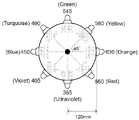
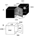
- test apparatus prepared for investigating the wavelength preference of the bagworm described in Example 1 was seen from above. It is a figure which shows the wavelength and the light intensity of each light source used for the test apparatus of FIG. It is a figure which shows the number of bagworms reaching each light source in the experiment of Example 1 using the test apparatus of FIG. It is a conceptual diagram of the test apparatus made in order to verify the propriety of the spout position control by light irradiation in a three-dimensional structure.
- A is a conceptual diagram of the entire test device
- B is a schematic diagram for explaining the surface inside the cage in which the bagworm is placed in the test device shown by A. It is an actual image of the test apparatus of FIG.
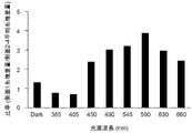
- A shows the whole image of the test equipment, and B shows the inside of the cage with 10 bagworms on the bottom. It is a figure which shows the ratio of the thread mass weight of each light source of Example 2 and a light emitting surface (side surface 1), and the average thread mass weight of a non-radiating side surface (side surface 2-4).
- the first aspect of the present invention is a method for controlling the behavior of bagworms. According to the method of the present invention, by irradiating the bagworm with light and changing the direction of radiating the light, the movement of the bagworm and its direction can be freely controlled, and the bagworm silk thread can be efficiently used. Obtainable.
- Bogworm is a general term for moth larvae belonging to the Lepidoptera and Psychidae families as described above. Moths of the bagworm family are distributed all over the world, but all larvae (bagworms) spell natural materials such as leaf pieces and branch pieces with silk thread spit out by themselves throughout the entire larval stage, and live in the nest that wears them. are doing. In addition, all species have a habit of advancing while spitting scaffolding silk thread, which serves as a foothold for preventing falling, in the direction of travel.
- the bagworm used in the present specification is a moth larva belonging to the family Bagworm, and may be of any kind, age and sex as long as it has the above-mentioned habit.
- the bagworm family includes Acanthopsyche, Anatolopsyche, Bacotia, Bambalina, Canephora, Chalioides, Dahlica, Diplodoma, Eumeta, Eumasia, Kozhantshikovia, Mahasena, Nipponopsyche, Paranarychia, Proutia, Psyche, Pteroma, Siederia, Triglo.
- the bagworm used in the present specification may be a species belonging to any genus.
- the age of the larva may be any age from the first instar to the last instar.
- a large bagworm is preferable.
- the last-instar larva is preferable, and if it is male and female, a large female is preferable.
- larger species are preferable.
- the large species Eumeta japonica and Eumeta minuscula are suitable species for use in the present invention.
- Bagworms are, in principle, bagworms that retain their nests. "Holding the nest" means that the bagworm carries the nest. As mentioned above, bagworms usually live with their nests.
- the naked bagworm which is artificially separated from the nest and the whole body is exposed to the outside world, may not necessarily follow the behavior control method of the present invention because the reconstruction of the nest is given the highest priority.
- bagworm silk thread refers to the silk thread spit out by the bagworm.
- the term “silk thread” is used to refer to bagworm silk thread unless otherwise specified.
- Bagworm silk thread includes single fiber, spit fiber and aggregate fiber.
- the "single fiber” is a filament of the smallest unit constituting a fiber component, and is also called a monofilament.
- the monofiber is mainly composed of fibroin protein.
- the bagworm silk thread is naturally spit out in the form of a difilament in which two single fibers are bound by the sericin protein of the adhesive. This difilament is called “spitting fiber”.
- Bagworm nests are composed of spit fibers.
- a fiber bundle in which a plurality of spit fibers are coupled to form a single fiber bundle is called an "aggregate fiber (multifilament)".
- raw silk corresponds to this aggregate fiber.
- the "scaffolding silk thread” is a silk thread that the bagworm spits out for movement as described above, and has a function as a scaffolding (scaffolding) for preventing the bagworm from falling from branches, leaves, or the like.
- the "nest silk thread” is a silk thread spit out for the construction of a nest, and is a bagworm silk thread for spelling leaf pieces and branch pieces and for making the inner wall of the nest, which is a living area, a comfortable environment.
- the bagworm silk thread in the present invention is intended for scaffolding silk thread for that purpose. Therefore, unless otherwise specified in the present specification, the term “bagworm silk thread” refers to scaffolding silk thread.
- the thread mass refers to an aggregate of threads composed only of bagworm scaffolding silk threads.
- the state of the thread mass is not limited.
- one or a plurality of bagworm silk threads may be intricately entwined to form a sheet like a non-woven fabric.
- the thread mass may have not only a two-dimensional shape but also a three-dimensional shape having a three-dimensional structure.
- the "base material” refers to a substrate for collecting bagworm silk thread. By arranging and moving the bagworm on this base material, the bagworm silk thread is spit out on the surface thereof. By collecting the bagworm silk thread on the surface of the base material after spitting, the bagworm scaffolding silk thread can be collected.
- induction means to artificially guide an organism to a specific substance or place by using the instinctive behavior of the organism.
- “behavioral control” means to freely manipulate the behavior of bagworms, that is, movements such as movement and direction change.
- the term “spreading position control” means that when the bagworm spits the scaffolding silk thread, the spitting action is freely operated so as to spit at a predetermined position.
- light mainly means artificial light emitted from a light source.
- any light may be included regardless of the wavelength range or the like. For example, it includes both the behavior control light and the spout position control light described above.
- the term “behavioral control light” refers to light having a wavelength that has the effect of attracting bagworms.
- the “light spitting position control light” refers to light having a wavelength that suppresses the movement of bagworms and causes the scaffolding silk thread to spit at a specific position.
- wavelength light means light having a predetermined wavelength. Therefore, in the case of wavelength light, the wavelength range of light is limited to some extent, unlike the case of simply expressing light. However, the range does not have to be specific.
- light having a wavelength peak means wavelength light having a peak wavelength
- the "peak wavelength” means a wavelength when the wavelength of the irradiation light has a mountain shape and the light intensity reaches a maximum value (peak), as shown by a to h in FIG. Further, the light at this time, that is, the wavelength light at the peak wavelength is often referred to as "peak light” in the present specification.
- the method of this embodiment includes a guidance step which is an essential step and a direction control step which is a selection step.
- a guidance step which is an essential step
- a direction control step which is a selection step.
- the "guidance step” is a step of irradiating a bagworm with behavior control light and inducing the bagworm in the light radiation direction. This step is a step utilizing phototaxis in which bagworms move in the direction of light radiation.
- the behavior control light may be light having a wavelength at which the bagworm exhibits positive phototaxis, and the wavelength and light intensity are not particularly limited. In order to induce bagworms in the light emission direction more efficiently, it is preferable to irradiate light having a specific wavelength as behavior control light.
- the “specific wavelength light” (often referred to as “specific wavelength light” in the present specification) in this step means a wavelength light having a high attraction to bagworms in the case of behavior control light.
- wavelength light in the range of 405 nm ⁇ 60 nm (345 nm or more and 465 nm or less), 405 nm ⁇ 55 nm (350 nm or more and 460 nm or less), or 405 nm ⁇ 50 nm (355 nm or more and 455 nm or less) is applicable. It is preferably wavelength light having a peak wavelength within the wavelength range. As shown in Example 1 described later, the wavelength light in this range has a strong attraction to bagworms as compared with other wavelength lights.
- the specific wavelength light When the specific wavelength light has a peak wavelength, it may be either monochromatic light having one peak wavelength in the specific wavelength region or composite light having a plurality of peak wavelengths in the wavelength region. It is preferably monochromatic light.
- “Irradiating light (to the bagworm)” means to irradiate the bagworm with any wavelength light, for example, in the case of behavior control light, the wavelength light in the range of 405 nm ⁇ 60 nm, 405 nm ⁇ 55 nm, or 405 nm ⁇ 50 nm. It means to irradiate. Even light that does not have a peak wavelength, such as light from a fluorescent lamp, can be selectively transmitted through a wavelength selection filter to selectively transmit only the wavelength light within the above range, and the transmitted wavelength light can be irradiated as specific wavelength light. can.
- “irradiating the bagworm” means that the bagworm directly exposes the eye that receives the light or the head where the eye is located.
- Light radiation direction means the direction in which light is emitted.
- the direction in which the light source is installed corresponds
- the direction of the reflecting surface of the reflective material corresponds.
- Irradiation of light to the beetle is preferably continuous irradiation, but pulsed light that repeats a light-dark period in an extremely short time like a fluorescent lamp or a dark period that can be recognized by the naked eye periodically or aperiodically during the irradiation period (for example). , 1 second or longer, preferably a dark period of several seconds) may be intermittent irradiation.
- the method of irradiating the target with light is not particularly limited as long as the method can irradiate the target bagworm with light.
- it may be either direct irradiation or indirect irradiation.
- Direct irradiation means to directly irradiate the bagworm with the light emitted from the light source.
- the light source may be directed at the bagworm and the light may be irradiated.
- the bagworm moves in the direction in which the light source is placed.
- indirect irradiation means that the light emitted from the light source is not directly applied to the bagworm, but is reflected by a reflective material or the like, and then the reflected light is applied to the bagworm.
- the light emitted from the light source may be reflected by a reflective material such as a mirror to irradiate the light toward the beetle.
- Indirect irradiation may be performed via a plurality of reflections by a plurality of reflective materials.
- care is taken so that the reflected light applied to the bagworm is the light having the specific wavelength. Indirect irradiation is particularly useful when the bagworm must be irradiated with light from a specific direction while the light source is fixed.
- the irradiation time for bagworms is not particularly limited.
- the above-mentioned behavior control light may be irradiated to the bagworm, but usually, after the bagworm has finished moving to the predetermined position, further irradiation of the behavior control light is unnecessary. Become.
- the bagworm after moving to a predetermined position, when the bagworm is retained around the position and the bagworm is actively spit out at that position, the bagworm continues to be at that position as described in the second aspect described later.
- the irradiation of the spout position control light may be continued.
- the number of bagworms treated by one light irradiation is not particularly limited.
- the type, number, and / or age of the bagworms to be placed are not limited as long as they are within the light irradiation range.
- all the individuals may be of the same species and / or the same age, or some populations may be of the same species and / or the same age.
- the bagworm can be guided in a predetermined direction, so that the bagworm is efficiently moved from the old feeding ground to the new feeding ground, for example, when feeding the bagworm in a breeding environment, not limited to the purpose of thread collection. It can also be used in some cases.
- the "direction control process” is a process of changing the traveling direction of the bagworm by changing the direction of light emission. As mentioned above, when the bagworm is irradiated with light, the bagworm moves in the direction of its light emission. Even during the movement, if the light radiation direction moves, the traveling direction also changes according to the movement. Thereby, the moving direction of the bagworm can be freely controlled.
- the means for changing the direction of light emission is not particularly limited.
- the light source may be arranged in a new direction in which the bagworm should be moved. If the light source cannot be moved, the base material itself may be moved so that the base material on which the bagworm is placed faces a predetermined direction with respect to the light source.
- the reflective material may be moved and / or rotated, and the number of the reflective material may be increased or decreased as necessary so that the bagworm can be irradiated with light from a predetermined position on the substrate. ..
- the direction of light emission is not limited.
- the predetermined direction in which the bagworm should be guided is the light emission direction. Further, the light emission direction can be changed not only once but a plurality of times as needed.
- a second aspect of the present invention is a method for controlling the position of bagworm spit.
- the present invention is based on a new finding that when a bagworm is irradiated with light having a wavelength range different from that of the behavior control light from a predetermined position, the bagworm's spitting behavior at the predetermined position is promoted.
- the method of this embodiment is also an embodiment of a method for collecting bagworm silk thread.
- the bagworm spouting position control method of the present invention it is possible to make the bagworm spit at a predetermined position on the substrate. Further, by combining with the bagworm movement control method of the first aspect, the bagworm can be guided to a predetermined position and the spit can be induced at that position.
- the method of this embodiment includes a yarn ejection step which is an essential step, and a guidance step and a direction control step which are selection steps. Hereinafter, each step will be specifically described.
- Thread ejection step is a step of irradiating a bagworm with a thread ejection position control light from a predetermined position and causing the bagworm to eject a thread at that position.
- the spit position control light When the bagworm is irradiated with the spit position control light, the spit at the light emission position is promoted. This process utilizes this characteristic.
- the wavelength and light intensity of the spout position control light are not particularly limited. In order to make the bagworm spit more efficiently, it is preferable to irradiate the bagworm with a specific wavelength light as the spit position control light.
- the specific wavelength light referred to here refers to wavelength light having a high spouting action on bagworms.
- the specific wavelength light of this step may be the same wavelength light as the specific wavelength light used in the movement control method of the bagworm of the first aspect, or may be a different wavelength light.
- the spouting position control light is preferably wavelength light having a high spouting action.
- 560nm ⁇ 150nm (410nm or more and 710nm or less), 560nm ⁇ 140nm (420nm or more and 700nm or less), 560nm ⁇ 130nm (430nm or more and 690nm or less), 560nm ⁇ 120nm (440nm or more and 680nm or less), or 560nm ⁇ 110nm (450nm).
- Wavelength light in the range of 670 nm or less is applicable.
- the basic configuration other than the wavelength related to the spout position control light conforms to the specific wavelength light in the induction step of the first aspect.
- the irradiation condition and the shading condition may be performed according to the induction step of the first aspect. Therefore, the description of the overlapping features will be omitted here.
- the "predetermined position” means the position where the bagworm should be spit. Usually, it refers to the desired position on the surface of the substrate on which the bagworm should be spit.
- the bagworm may be placed at a predetermined position, or the bagworm may be guided and placed at a predetermined position from another place by a guidance step and a direction control step described later. May be good.
- placement of bagworms as used herein means that the bagworms are positioned at predetermined positions for the purpose of collecting bagworm silk threads.
- the number of bagworms placed in this process does not matter.
- one head may be placed at a predetermined position, or a plurality of heads may be placed.
- the type and age of the bagworms to be placed do not matter.
- each individual may be of the same species and / or the same age, or may be of a different species and / or a different age.
- the period of this process is not particularly limited. It depends on the type, age, and number of bagworms used, but in any case, it may be continued until the required amount is spit out on a predetermined position.
- a predetermined position As an example, when using one last-instar Eumeta varieties to spit on a circular substrate with a diameter of 9 cm at a predetermined position, 1 day or more, 2 days or more, 3 days or more, 4 days or more, 5 days or more. , 6 days or more, 7 days or more can be spit. Since the bagworm scaffolding silk thread is spit out with movement as described above, the amount of silk thread obtained is in principle proportional to the movement distance of the bagworm.
- the time required for the threading process is shorter when the bagworms are spit out by a plurality of heads than when the bagworms are spit out alone.
- bagworms often stop spitting during this process because they continue to spit without feeding. In such a case, it is possible to replace it with a new bagworm and continue the thread ejection process.
- the temperature and humidity during this process should be constant or little change so that the amount of bagworm spit per unit time is large.
- the temperature should be around 25 ° C, for example, 20 ° C to 30 ° C, or 23 ° C to 27 ° C, and the humidity should be around 50%, for example, 40% to 65%, or 45% to 60%. Is preferable.
- the light-dark period in this step is not particularly limited and may be only the light period, but a periodic light-dark period may be imparted. For example, in 24 hours, the light period is 6 hours to 18 hours, 7 hours to 17 hours, 8 hours to 16 hours, 9 hours to 15 hours, 10 hours to 14 hours, 11 hours to 13 hours, or 12 hours.
- the cycle may be such that the rest is the dark period.
- the material constituting the base material on which the bagworm is placed is not particularly limited as long as the bagworm silk thread can be fixed to the surface when the bagworm moves.
- glass including hollow
- metal synthetic resin (including thermoplastic resin, thermosetting resin, synthetic rubber), ceramics, or paper or plant pieces (including wood pieces), animal pieces (eg bone).
- Synthetic resins include polyethylene, polypropylene, polystyrene, vinyl acetate, cellulose acetate, acrylic resins, polycarbonate and the like.
- the base material is preferably a transparent base material or a translucent base material.
- the transparent base material has a very high light transmittance and has a property that the opposite side can be seen through the material.
- glass polyethylene, polystyrene, acrylic resin and the like can be mentioned.
- a translucent base material is a base material that has the property of transmitting light, but has a low light transmittance, so that the shape on the opposite side cannot be clearly recognized or hardly recognized through the material. say.
- polypropylene, frosted glass and the like can be mentioned.
- the thickness of the base material is not limited. It may be determined as appropriate in consideration of the manufacturing cost of the base material, the rigidity, the ease of processing in the subsequent process, and the like.
- the average thickness of the base material is preferably 0.5 mm or more, 0.6 mm or more, 0.7 mm or more, 0.8 mm or more, 0.9 mm or more, 1.0 mm or more, 1.2 mm or more, or 1.5 mm or more, and more preferably 3.0 mm or less. It may be 2.8 mm or less, 2.5 mm or less, 2.2 mm or less, or 2.0 mm or less.
- the base material When the base material is composed of a thin film whose average thickness is less than 0.5 mm, 0.4 mm, 0.3 mm, 0.2 mm, or 0.5 mm, the base material itself does not have the rigidity to maintain a constant shape. It may be placed on a suitable support.
- the "support” is a member that can impart rigidity and / or shape to the base material.
- the base material is placed on the surface.
- the material of the support is not particularly limited as long as it has a rigidity sufficient to maintain a certain shape.
- the support is preferably a transparent base material or a translucent base material as well as the base material.
- the shape and size of the base material used in this process are not limited.
- the shape may be, for example, a sheet-like or plate-like planar shape, a simple or complicated three-dimensional shape, or a combination thereof. Even if a base material (three-dimensional structure) having a three-dimensional shape, which is normally difficult to spit, can be spit on the entire surface according to the present invention.
- the size of the base material may be adjusted as needed, but considering that the scaffolding silk thread is a bagworm silk thread that is spit out as it moves, the lower limit should be equal to or larger than the body length of the bagworm. Is preferable.
- the major axis and the major axis can be 1 cm or more, 2 cm or more, 3 cm or more, 4 cm or more, or 5 cm or more.
- the upper limit of the size of the base material does not matter, but if the major axis or major axis is 10 cm or more, 15 cm or more, 20 cm or more, 25 cm or more, or 30 cm or more, those who make multiple bagworms spit. Is preferable.
- the guidance step and direction control step of the present invention are selective steps in the bagworm spouting position control method. The description of the specific procedure and the like of these steps is based on the guidance step and the direction control step in the bagworm movement control method of the first aspect.
- the bagworm can spit out the scaffolding silk thread at a predetermined position by the spitting step, which is an essential step.
- the bagworm's threading behavior is induced, and as a result, the movement of the bagworm is suppressed. Therefore, in order to continue spouting at the next predetermined position after the spitting at the predetermined position is completed, the behavior control method of the bagworm of the first aspect may be incorporated into the method of this aspect.
- the bagworm is newly determined. Can be guided to the position of. After reaching a new predetermined position, the irradiation light may be switched from the behavior control light to the spouting position control light again, and the spitting behavior may be induced at that position. By repeating this, even when there are a plurality of predetermined positions where the scaffolding silk thread should be spit out, it becomes possible to continuously induce the spitting thread.
- the induction step and the direction control step may be performed before or after the spouting step, and the order thereof does not matter.
- the scaffolding silk thread can be spit out at a specific position on the surface of the substrate having any shape regardless of the planar structure or the three-dimensional structure. It is also possible to spit on the entire surface of a three-dimensional structure having a complicated shape. As a result, it is possible to produce a thread mass of bagworm silk thread made of scaffold silk thread having a desired three-dimensional shape. Such a thread mass can also have a complicated shape that cannot be produced by pressing a sheet-shaped bagworm silk thread.
- the base material used in the method for producing the minumushi silk yarn a material that can be dissolved in a solvent that does not physically or chemically damage the minumushi silk yarn, the base material is dissolved with the solvent after the yarn ejection step.
- a thread mass having a desired shape composed of only the silk thread of Minomushi.
- Such thread lumps can be used, for example, as scaffold materials in regenerative medicine.
- a third aspect of the present invention is a bagworm silk thread collecting device.
- the bagworm silk thread collecting device of the present invention is a device that embodies the bagworm spouting position control method of the second aspect, and is predetermined by arranging the base material to be spit out on the base material. At the position, the bagworm can be made to spit out the scaffolding thread.
- the bagworm silk thread picking device of the present invention includes a first light source as an essential component and a second light source and / or a housing as a selective component.
- a first light source as an essential component
- a second light source and / or a housing as a selective component.
- each component will be specifically described.
- the first light source is the spit position control light according to the second aspect of the method for controlling the spit position of the beetle, specifically, 560 nm ⁇ 150 nm, 560 nm ⁇ 140 nm, 560 nm having a high spit action on the beetle. It is a light source that can emit light in the visible light range of ⁇ 130 nm, 560 nm ⁇ 120 nm, or 560 nm ⁇ 110 nm.
- the first light source is configured to be able to radiate from an arbitrary direction with respect to the base material installed in the apparatus.
- the first light source can also be used as a light source for controlling the position of the bagworm spout.
- the first light source is not particularly limited as long as it can radiate wavelength light in the wavelength range.
- Preferred light sources include, for example, LEDs. Since the wavelength spectrum of the LED shows a waveform having a peak light of a specific wavelength, it is preferable as the light source of the present invention. However, as described above, even a light source that emits light having no peak wavelength, such as a fluorescent lamp or a mercury lamp, can irradiate only the transmitted light selected through the wavelength selection filter as the spout position control light. If so, this is not the case.
- each light source may be installed so as to face the same direction with respect to the base material, or each may be installed so as to face a different direction with respect to the base material.
- each light source may be a light source capable of radiating light having a different wavelength, for example, light having a different peak wavelength, as long as it is a light source capable of radiating light having a wavelength in the wavelength range.
- each light source may be configured to emit light at the same time or at different timings.
- the first light source may be movable.
- Examples include a configuration in which the light source can move on the rail.
- the spout position control light emitted from the first light source may be configured to directly irradiate the base material arranged in the apparatus, or may be indirectly applied to the base material via one or a plurality of reflective materials. It may be configured to be irradiated.
- the device may include one or more reflectors. Each reflective material may be configured so that the reflection angle can be changed in order to adjust the reflection position of light.
- the “second light source” can emit the behavior control light described in the method for controlling the movement of bagworms in the first aspect, specifically, wavelength light in the range of 405 nm ⁇ 60 nm, 405 nm ⁇ 55 nm, or 405 nm ⁇ 50 nm.
- Light source In the apparatus of the present invention, the second light source is configured to be able to radiate to the substrate from an arbitrary direction in order to move the bagworm to an arbitrary position on the substrate installed in the apparatus.
- the second light source can also be used as a light source for controlling the behavior of bagworms.
- the first light source and the second light source can be used in combination. In that case, it suffices to be configured to be able to radiate wavelength light in the wavelength range where both the attracting action and the spitting action are the highest. For example, wavelength light in the range of 410 nm or more and 465 nm or less can be mentioned.
- the basic configuration of the second light source is basically the same as the configuration of the first light source except that the range of the emitted wavelength light is different, so the description here is omitted.
- housing is a component that provides a light-shielding environment for the bagworm silk thread collecting device of the present invention, and is a selective component of the device.
- the shading environment is usually provided inside the housing. Therefore, the housing in the present device is configured so that at least the bagworm and the base material for spitting can be arranged inside the housing.
- the first light source or the second light source, or their reflective materials may be arranged inside the housing.
- Base material is not a component of the bagworm silk thread collecting device of the present invention, but a member provided for the device.
- the material and shape of the base material are the same as those of the base material described in the yarn ejection step in the method for controlling the yarn ejection position of the bagworm in the second aspect.
- the bagworm silk thread collecting device of the present invention is an invention in which the bagworm spouting position control method of the second aspect is incorporated into an apparatus.
- the bagworm can spit the scaffolding thread at a predetermined position on the base material. According to this device, it is possible to spit at a predetermined position on the surface of a base material having a complicated three-dimensional structure.
- Example 1 Verification of wavelength light that induces bagworms> (Purpose) In order to confirm the light inducibility of bagworms, wavelength light having various wavelength peaks is simultaneously irradiated from the side surface to verify which wavelength light the bagworm is attracted to. (Method) For bagworms, 20 last-instar larvae of the same size were used.
- the test device is entirely composed of a light-shielding material with reference to the test device (Takumi Ogino et al., 2015, Journal of the Japanese Society of Applied Animal and Insects, 59: 10-13) developed for the purpose of investigating the wavelength preference of stink bugs.
- a device in which eight light sources with different wavelengths were placed on the side surface of a cylindrical container with a radius of 120 mm and a height of 30 mm at an angular interval of 45 ° (Fig. 1).
- the light sources include (a) 365 nm (ultraviolet light), (b) 405 nm (purple light), (c) 450 nm (blue light), (d) 490 nm (blue-green light), and (e) 545 nm.
- LEDs (FIG. 2) having peak wavelengths at (green light), (f) 590 nm (yellow light), (g) 630 nm (orange light) and (h) 660 nm (red light) were used. As shown in FIG. 2, the light intensities of the LEDs used are almost the same.
- FIG. 3 shows the number of heads reaching each light source wavelength.
- FIG. 3 shows the number of heads reaching each light source wavelength.
- the light of each wavelength was simultaneously irradiated, many individuals of the bagworm were attracted to the short wavelength light rather than the long wavelength light.
- the shorter the wavelength the stronger the attraction, and the wavelength range of 60 nm before and after around 405 nm is the most effective. This result suggests that the bagworm can be guided in the light radiation direction by irradiating the bagworm with behavioral control light of 405 nm ⁇ 60 nm.
- Example 2 Behavior control and spout position control on a desired surface of a three-dimensional structure> (Purpose)
- the bagworm can be effectively guided in the light radiation direction of the behavior control light by irradiating it with the behavior control light.
- the bagworm can efficiently produce a yarn mass at a predetermined position of the three-dimensional structure by irradiating the bagworm with the yarn ejection position control light.
- the last-instar larvae of the same size Eumeta minuscula were used.
- this device consists of two cubes (cage; 0401, 0403) composed of a light-shielding non-reflective member with a side of 100 mm, a light-shielding non-reflective square plate (0402) with a side of 100 mm, and a square plate (0402) with a side of 100 mm. It consists of four main parts of the light source (0406).
- the square plate (0402) has a large square window (0405) in the center, and a nylon mesh described later is attached to this window.
- the two cubes (0401, 0403) have a box shape with one of the six sides open, and are configured to open and close each other's open faces with a square plate (0402) sandwiched between them. .. When the open surface is closed, the interior space of the two cubes (0401, 0403) is separated by the square plate (0402), forming two dark chambers. Bagworms are placed in one of the cages (0401). Nylon mesh (0404) for assisting the movement of bagworms is attached to all six sides on the inner wall surface of the cage in which the bagworms are placed. On the other hand, a light source (0406) is provided on the opposite side of the open surface so that the internal space can be irradiated with light.
- the light emitted from the light source with the open surface closed reaches the cage (0401) through the window (0405).
- the surface through which light can enter the cage is only the light emitting surface, the other surfaces are completely shielded from light, and there is no intrusion of light from the outside.
- the non-reflective member does not reflect the light that has entered from the light emitting surface on each surface.
- Light sources include ultraviolet LED (maximum wavelength 365 nm), purple LED (405 nm), blue LED (450 nm), blue-green LED (490 nm), green LED (545 nm), yellow LED (590 nm), and orange LED.
- Eight types of (630 nm) and red LED (660 nm) were prepared, and the weight of the thread mass of the beetle on each surface was set under nine conditions including the dark experimental area where no light source was installed for negative control. Was compared.
- the 10 bagworms introduced were replaced with new bagworms that had been sufficiently fed in advance every 2 to 4 days, and the experiment was continued for a total of 13 days. During the experiment, the temperature of the test system was maintained at 26 ° C.
- each side surface has a light emitting surface as "side surface 1" and clockwise as “side surfaces 2 to 4" when viewed from above.
- the thread mass weight was measured only under the dark condition of the negative control, but the bottom surface was excluded from the measurement target. The reason for this is that, as for the upper surface, it was clarified from the results described later that the instinctive property that the bagworm prefers high places is maintained even in the dark and that the bagworm is spit out regardless of the light induction.
- the bottom surface is the place where bagworms are first installed, and when moving to each surface, the thread is also spit out regardless of the light induction.
- Figure 6 shows the results. Under light irradiation conditions, it was confirmed that the thread mass weight of the side surface 1 which is the light emitting surface is more than twice as much as the average thread mass weight of the other side surfaces except when the short wavelength light of 365 nm and 405 nm is irradiated. Surprisingly, the weight ratio of the yarn mass on the side surface 1 was the lowest when the bagworm was irradiated with the most strongly attracted wavelength light of 405 nm in Example 1, whereas it was from 450 nm. It showed a high value when irradiated with 660 nm wavelength light. This result suggests that the wavelength of the behavior control light having a high attracting action and the wavelength of the spitting position control light having a high spitting action do not always match.
Landscapes
- Life Sciences & Earth Sciences (AREA)
- Engineering & Computer Science (AREA)
- Environmental Sciences (AREA)
- Mechanical Engineering (AREA)
- Textile Engineering (AREA)
- Animal Behavior & Ethology (AREA)
- Zoology (AREA)
- Animal Husbandry (AREA)
- Biodiversity & Conservation Biology (AREA)
- Micro-Organisms Or Cultivation Processes Thereof (AREA)
- Apparatus Associated With Microorganisms And Enzymes (AREA)
- Catching Or Destruction (AREA)
Abstract
Description
(2)前記行動制御光の波長が405nm±60nmである、(1)に記載の行動制御方法。
(3)前記光放射方向を変えることでミノムシの誘導方向を転換させる工程を含む、(1)又は(2)に記載の行動制御方法。
(4)遮光条件下で行う、(1)~(3)のいずれかに記載の行動制御方法。
(5)基材上の所定の位置からミノムシに対して吐糸位置制御光を照射して、該位置でミノムシに吐糸させる工程を含む、ミノムシの吐糸位置制御方法。
(6)前記吐糸位置制御光の波長が560nm±150nmである、(5)に記載の吐糸位置制御方法。
(7)前記基材上の所定の位置からミノムシに対して波長405nm±60nmの行動制御光を照射し、該位置にミノムシを誘導する工程を含む、(5)又は(6)に記載の吐糸位置制御方法。
(8)遮光条件下で行う、(5)~(7)のいずれかに記載の吐糸位置制御方法。
(9)前記基材が3次元構造体である、(5)~(8)のいずれかに記載の吐糸位置制御方法。
(10)前記基材が透明基材又は透光性基材である、(5)~(9)のいずれかに記載の吐糸位置制御方法。
(11)(5)~(10)のいずれかに記載のミノムシの吐糸位置制御方法を用いて得られるミノムシ絹糸の糸塊生産方法。
(12)ミノムシに吐糸させるための基材に対して吐糸位置制御光を任意の方向から放射可能な一又は複数の光源を備えたミノムシ絹糸採糸装置。
(13)前記吐糸位置制御光の波長が560nm±150nmである、(12)に記載の装置。
(14)前記基材に対して波長405nm±60nmの行動制御光を任意の方向から放射可能な一又は複数の光源をさらに備えた、(12)又は(13)に記載の装置。
(15)前記光源が可動式である、(12)~(14)のいずれかに記載の装置。
(16)内部に遮光環境を有する筐体を備えた、(12)~(15)のいずれかに記載の装置。
(17)ミノムシの行動を制御するための波長405nm±60nmの範囲の光を放射可能な光源の使用。
(18)ミノムシの吐糸位置を制御するための波長560nm±150nmの範囲の光を放射可能な光源の使用。
本明細書は本願の優先権の基礎となる日本国特許出願番号2020-164314号の開示内容を包含する。
1-1.概要
本発明の第1の態様は、ミノムシの行動制御方法である。本発明の方法によれば、ミノムシに光を照射し、またその光を放射する方向を変えることで、ミノムシの移動やその方向を自在に制御することができ、ひいては、ミノムシ絹糸を効率的に得ることができる。
本明細書で頻用する以下の用語について、以下の通り定義する。
「ミノムシ」とは、前述のようにチョウ目(Lepidoptera)ミノガ科(Psychidae)に属する蛾の幼虫の総称をいう。ミノガ科の蛾は世界中に分布するが、いずれの幼虫(ミノムシ)も全幼虫期を通して、自ら吐糸した絹糸で葉片や枝片等の自然素材を綴り、それらを纏った巣の中で生活している。また、いずれの種も移動に際しては、進行方向先に落下防止の足掛かりとなる足場絹糸を吐糸しながら進む習性を有する。したがって、本明細書で使用するミノムシは、ミノガ科に属する蛾の幼虫であって、前記習性を有する限り、種類、齢及び雌雄は問わない。例えば、ミノガ科には、Acanthopsyche、Anatolopsyche、Bacotia、Bambalina、Canephora、Chalioides、Dahlica、Diplodoma、Eumeta、Eumasia、Kozhantshikovia、Mahasena、Nipponopsyche、Paranarychia、Proutia、Psyche、Pteroma、Siederia、Striglocyrbasia、Taleporia、Theriodopteryx、Trigonodoma等の属が存在するが、本明細書で使用するミノムシは、いずれの属に属する種であってもよい。また、幼虫の齢は、初齢から終齢に至るまで、いずれの齢であってもよい。ただし、ミノムシ絹糸を得ることを目的とする場合には、大型のミノムシである方が好ましい。例えば、同種であれば終齢幼虫ほど好ましく、雌雄であれば大型となる雌の方が好ましい。またミノガ科内では大型種ほど好ましい。例えば、大型種のオオミノガ(Eumeta japonica)やチャミノガ(Eumeta minuscula)は、本発明で用いる種として好適である。ミノムシは、原則として巣を保持したミノムシである。「巣を保持した」とは、ミノムシが巣を携帯した状態をいう。前述のようにミノムシは、通常、自身の巣と共に生活している。摂食時や移動時も、虫体の一部を巣外に露出させるのみで、全幼虫期を通じて巣から全身を露出させることはない。一方、人為的に巣と分離して、外界に全身を露出させた裸状態のミノムシは、巣の再構築を最優先するため、本発明の行動制御方法に必ずしも準じない可能性がある。
本態様の方法は、必須工程である誘導工程と、選択工程である方向制御工程を含む。以下、各工程について具体的に説明をする。
「誘導工程」とは、行動制御光をミノムシに照射して、その光放射方向にミノムシを誘導する工程である。本工程は、ミノムシが光放射方向に向かって移動する走光性を利用した工程である。
「方向制御工程」は、光放射方向を変えることで、ミノムシの進行方向を転換させる工程である。前述のように、ミノムシに光を照射した場合、ミノムシはその光放射方向に向かって移動する。その移動途中であっても、光放射方向が移動すれば、その移動に合わせて進行方向も変化する。それによってミノムシの移動する方向を自在に制御することができる。
2-1.概要
本発明の第2の態様は、ミノムシの吐糸位置制御方法である。本発明は、行動制御光とは主要な波長域の異なる光を所定の位置からミノムシに照射したときに、その所定の位置でのミノムシの吐糸行動が促進されるという新たな知見に基づく。本態様の方法は、ミノムシ絹糸の採糸方法の一実施形態でもある。
本態様の方法は、必須工程である吐糸工程と、選択工程である誘導工程及び方向制御工程を含む。以下、各工程について具体的に説明をする。
「吐糸工程」は、吐糸位置制御光を、所定の位置からミノムシに照射し、該位置でミノムシに吐糸させる工程である。ミノムシは、吐糸位置制御光を照射された場合、その光放射位置での吐糸が促進される。本工程は、この特性を利用している。
本発明の誘導工程及び方向制御工程は、ミノムシの吐糸位置制御方法において選択的工程である。これらの工程の具体的な手順等についての説明は、第1態様のミノムシの移動制御方法における誘導工程及び方向制御工程に準ずる。
本発明のミノムシの吐糸位置制御方法によれば、平面構造や3次元構造を問わず、あらゆる形状の基材表面上の特定の位置に足場絹糸を吐糸させることができる。また、複雑な形状を有する3次元構造体の全表面上に吐糸させることも可能となる。その結果、所望の立体形状を有する足場絹糸からなるミノムシ絹糸の糸塊を生産することができる。そのような糸塊は、シート状のミノムシ絹糸をプレス加工しても生産することのできない複雑な形状とすることも可能である。また、ミノムシ絹糸の生産方法に使用する基材を、ミノムシ絹糸を物理的又は化学的に損傷しない溶剤に溶解可能な素材にしておくことで、吐糸工程後、基材をその溶剤で溶解処理することによって、ミノムシ絹糸のみで構成された所望の形状を有する糸塊を生産することもできる。そのような糸塊は、例えば、再生医療における足場(scaffold)材料として利用することができる。
3-1.概要
本発明の第3の態様は、ミノムシ絹糸採糸装置である。本発明のミノムシ絹糸採糸装置は、前記第2態様のミノムシの吐糸位置制御方法を具現化した装置であって、吐糸対象の基材を装置に配置することで基材上の所定の位置でミノムシに足場糸を吐糸させることができる。
本発明のミノムシ絹糸採糸装置は、必須の構成要素として第1光源を備え、選択的構成要素として第2光源及び/又は筐体を備える。以下、それぞれの構成要素について具体的に説明をする。
「第1光源」は、第2態様のミノムシの吐糸位置制御方法に記載の吐糸位置制御光、具体的にはミノムシに対する吐糸作用の高い560nm±150nm、560nm±140nm、560nm±130nm、560nm±120nm、又は560nm±110nmの可視光域の範囲の光を放射可能な光源である。本発明の装置において、第1光源は、本装置内に設置される基材に対して任意の方向から放射可能なように構成されている。第1光源をミノムシの吐糸位置を制御するための光源として使用することもできる。
「第2光源」は、第1態様のミノムシの移動制御方法に記載の行動制御光、具体的には405nm±60nm、405nm±55nm、又は405nm±50nmの範囲の波長光を放射可能な光源である。本発明の装置において、第2光源は、装置内に設置される基材上の任意の位置にミノムシを移動させるために任意の方向から基材に放射可能なように構成されている。第2光源をミノムシの行動を制御するための光源として使用することもできる。
「筐体」は、本発明のミノムシ絹糸採糸装置に遮光環境を提供する構成部材で、本装置の選択的構成要素である。遮光環境は、通常、筐体内部で提供される。したがって、本装置における筐体は、少なくともミノムシ及び吐糸用基材をその内部に配置できるように構成されている。第1光源若しくは第2光源、又はそれらの反射材が筐体内部に配置されていてもよい。
「基材」は、本発明のミノムシ絹糸採糸装置における構成要素ではなく、当該装置に供される部材である。基材の材質及び形状等については、第2態様のミノムシの吐糸位置制御方法において吐糸工程に記載の基材に準ずる。
本発明のミノムシ絹糸採糸装置は、前記第2態様のミノムシの吐糸位置制御方法を装置化した発明である。装置に吐糸対象の基材とミノムシを配置し、実行することで基材上の所定の位置においてミノムシに足場糸を吐糸させることができる。この装置によれば、複雑な3次元構造を有する基材表面の所定の位置での吐糸が可能となる。
(目的)
ミノムシの光誘導性を確認するために、様々な波長ピークを有する波長光を側面から同時照射して、ミノムシがいずれの波長光に誘引されるかを検証する。
(方法)
ミノムシは、同サイズのチャミノガの終齢幼虫20頭を使用した。
図3に各光源波長への到達頭数を示す。図3で示すように、各波長光を同時照射した場合には、ミノムシは長波長光よりも短波長光に多くの個体が誘引された。ただし、波長が短いほど強く誘引されるのではなく、405nmを中心とする前後60nmの波長範囲が最も効果的であることが明らかとなった。この結果は、ミノムシに405nm±60nmの行動制御光を照射することで、ミノムシをその光放射方向に誘導できることを示唆している。
(目的)
実施例1では、行動制御光を照射することでミノムシを効果的に行動制御光の光放射方向に誘導できることを確認した。本実施例では、ミノムシに吐糸位置制御光を照射することで、3次元構造体の所定の位置に効率的に糸塊を生産できることを検証する。
(材料及び方法)
ミノムシは、同サイズのチャミノガの終齢幼虫を使用した。
陰性対照の暗黒条件下では、4側面に対して上面の糸塊重量が最も多い結果となった(データ示さず)。これは、ミノムシが高所へ移動し、その位置に留まろうとする本能的な性質による。そこで、ミノムシの上方移動による影響を排除し、光の波長による吐糸行動への影響のみを比較するため、光放射面(側面1)上の糸塊重量と他の3側面(側面2、3、4)の平均糸塊重量との比を算出して、各波長光の比較を行った。
本明細書で引用した全ての刊行物、特許及び特許出願はそのまま引用により本明細書に組み入れられるものとする。
Claims (18)
- ミノムシに行動制御光を照射して、その光放射方向にミノムシを誘導する工程を含むミノムシの行動制御方法。
- 前記行動制御光の波長が405nm±60nmである、請求項1に記載の行動制御方法。
- 前記光放射方向を変えることでミノムシの誘導方向を転換させる工程を含む、請求項1又は2に記載の行動制御方法。
- 遮光条件下で行う、請求項1~3のいずれか一項に記載の行動制御方法。
- 基材上の所定の位置からミノムシに対して吐糸位置制御光を照射して、該位置でミノムシに吐糸させる工程を含む、ミノムシの吐糸位置制御方法。
- 前記吐糸位置制御光の波長が560nm±150nmである、請求項5に記載の吐糸位置制御方法。
- 前記基材上の所定の位置からミノムシに対して波長405nm±60nmの行動制御光を照射し、該位置にミノムシを誘導する工程を含む、請求項5又は6に記載の吐糸位置制御方法。
- 遮光条件下で行う、請求項5~7のいずれか一項に記載の吐糸位置制御方法。
- 前記基材が3次元構造体である、請求項5~8のいずれか一項に記載の吐糸位置制御方法。
- 前記基材が透明基材又は透光性基材である、請求項5~9のいずれか一項に記載の吐糸位置制御方法。
- 請求項5~10のいずれか一項に記載のミノムシの吐糸位置制御方法を用いて得られるミノムシ絹糸の糸塊生産方法。
- ミノムシに吐糸させるための基材に対して吐糸位置制御光を任意の方向から放射可能な一又は複数の光源を備えたミノムシ絹糸採糸装置。
- 前記吐糸位置制御光の波長が560nm±150nmである、請求項12に記載の装置。
- 前記基材に対して波長405nm±60nmの行動制御光を任意の方向から放射可能な一又は複数の光源をさらに備えた、請求項12又は13に記載の装置。
- 前記光源が可動式である、請求項12~14のいずれか一項に記載の装置。
- 内部に遮光環境を有する筐体を備えた、請求項12~15のいずれか一項に記載の装置。
- ミノムシの行動を制御するための波長405nm±60nmの範囲の光を放射可能な光源の使用。
- ミノムシの吐糸位置を制御するための波長560nm±150nmの範囲の光を放射可能な光源の使用。
Priority Applications (4)
| Application Number | Priority Date | Filing Date | Title |
|---|---|---|---|
| JP2022554091A JP7710687B2 (ja) | 2020-09-30 | 2021-09-30 | ミノムシの行動制御方法及び吐糸位置制御方法 |
| CN202180066472.5A CN116209797A (zh) | 2020-09-30 | 2021-09-30 | 蓑蛾虫的行为控制方法和吐丝位置控制方法 |
| EP21875776.3A EP4223913B1 (en) | 2020-09-30 | 2021-09-30 | Behavior control method and spinning position control method for bagworms |
| US18/246,733 US20230287599A1 (en) | 2020-09-30 | 2021-09-30 | Behavior control method and spinning position control method for bagworms |
Applications Claiming Priority (2)
| Application Number | Priority Date | Filing Date | Title |
|---|---|---|---|
| JP2020164314 | 2020-09-30 | ||
| JP2020-164314 | 2020-09-30 |
Publications (1)
| Publication Number | Publication Date |
|---|---|
| WO2022071480A1 true WO2022071480A1 (ja) | 2022-04-07 |
Family
ID=80950482
Family Applications (1)
| Application Number | Title | Priority Date | Filing Date |
|---|---|---|---|
| PCT/JP2021/036079 Ceased WO2022071480A1 (ja) | 2020-09-30 | 2021-09-30 | ミノムシの行動制御方法及び吐糸位置制御方法 |
Country Status (5)
| Country | Link |
|---|---|
| US (1) | US20230287599A1 (ja) |
| EP (1) | EP4223913B1 (ja) |
| JP (1) | JP7710687B2 (ja) |
| CN (1) | CN116209797A (ja) |
| WO (1) | WO2022071480A1 (ja) |
Citations (5)
| Publication number | Priority date | Publication date | Assignee | Title |
|---|---|---|---|---|
| WO2012165477A1 (ja) | 2011-06-01 | 2012-12-06 | スパイバー株式会社 | タンパク質繊維及びその製造方法 |
| WO2017022333A1 (ja) * | 2015-07-31 | 2017-02-09 | 国立研究開発法人農業・食品産業技術総合研究機構 | 捕食性昆虫の誘引又は定着方法 |
| JP2018197415A (ja) * | 2016-06-02 | 2018-12-13 | 国立研究開発法人農業・食品産業技術総合研究機構 | 長尺ミノムシ絹糸の生産方法及びその生産装置 |
| JP2019116701A (ja) * | 2017-12-27 | 2019-07-18 | 国立研究開発法人農業・食品産業技術総合研究機構 | ミノムシ絹糸の採糸方法 |
| JP2020164314A (ja) | 2019-03-29 | 2020-10-08 | 京セラドキュメントソリューションズ株式会社 | 搬送装置及び画像形成装置 |
Family Cites Families (1)
| Publication number | Priority date | Publication date | Assignee | Title |
|---|---|---|---|---|
| KR101275688B1 (ko) * | 2011-12-22 | 2013-06-17 | 영농조합법인꿈틀 | Led조명을 이용한 누에 수집유인장치 |
-
2021
- 2021-09-30 CN CN202180066472.5A patent/CN116209797A/zh active Pending
- 2021-09-30 US US18/246,733 patent/US20230287599A1/en active Pending
- 2021-09-30 JP JP2022554091A patent/JP7710687B2/ja active Active
- 2021-09-30 WO PCT/JP2021/036079 patent/WO2022071480A1/ja not_active Ceased
- 2021-09-30 EP EP21875776.3A patent/EP4223913B1/en active Active
Patent Citations (5)
| Publication number | Priority date | Publication date | Assignee | Title |
|---|---|---|---|---|
| WO2012165477A1 (ja) | 2011-06-01 | 2012-12-06 | スパイバー株式会社 | タンパク質繊維及びその製造方法 |
| WO2017022333A1 (ja) * | 2015-07-31 | 2017-02-09 | 国立研究開発法人農業・食品産業技術総合研究機構 | 捕食性昆虫の誘引又は定着方法 |
| JP2018197415A (ja) * | 2016-06-02 | 2018-12-13 | 国立研究開発法人農業・食品産業技術総合研究機構 | 長尺ミノムシ絹糸の生産方法及びその生産装置 |
| JP2019116701A (ja) * | 2017-12-27 | 2019-07-18 | 国立研究開発法人農業・食品産業技術総合研究機構 | ミノムシ絹糸の採糸方法 |
| JP2020164314A (ja) | 2019-03-29 | 2020-10-08 | 京セラドキュメントソリューションズ株式会社 | 搬送装置及び画像形成装置 |
Non-Patent Citations (4)
| Title |
|---|
| KUWANA Y ET AL., PLOS ONE, DOI: 10.1371/JOURNAL.PONE.0105325, 2014 |
| See also references of EP4223913A4 |
| SHIGEYOSI OHSAKI, SEN'I GAKKAISHI (SEN'I TO KOGYO, vol. 58, 2002, pages 74 - 78 |
| TAKUMI OGINO ET AL., THE JAPANESE JOURNAL OF APPLIED ENTOMOLOGY AND ZOOLOGY, vol. 59, 2015, pages 10 - 13 |
Also Published As
| Publication number | Publication date |
|---|---|
| EP4223913C0 (en) | 2025-12-10 |
| EP4223913A4 (en) | 2024-10-09 |
| US20230287599A1 (en) | 2023-09-14 |
| CN116209797A (zh) | 2023-06-02 |
| JPWO2022071480A1 (ja) | 2022-04-07 |
| EP4223913B1 (en) | 2025-12-10 |
| JP7710687B2 (ja) | 2025-07-22 |
| EP4223913A1 (en) | 2023-08-09 |
Similar Documents
| Publication | Publication Date | Title |
|---|---|---|
| EP3973768B1 (en) | Lighting system controlling ultraviolet intensity over a surface of a light sensitive object | |
| JP6802267B2 (ja) | 飛翔昆虫を誘引し捕獲するための装置及び方法 | |
| US20170086430A1 (en) | Alternating angle controlled wavelength lighting system to stimulate feeding in larval fish | |
| CN113721006A (zh) | 昆虫运动性活动节律及睡眠行为磁生物学响应研究装置 | |
| NO841387L (no) | Fremgangsmaate ved forbedring i husdyravl | |
| WO2015166292A1 (en) | Device and fence for controlling the queen bee's egg-laying process | |
| Chen et al. | Phototactic behavior of the Armand pine bark weevil, Pissodes punctatus | |
| WO2022071480A1 (ja) | ミノムシの行動制御方法及び吐糸位置制御方法 | |
| Luo et al. | Phototactic behavior of Scleroderma guani (hymenoptera: bethylidae)-parasitoid of Pissodes punctatus (Coleoptera: Curculionidae) | |
| Duehl et al. | The influence of light on small hive beetle (Aethina tumida) behavior and trap capture | |
| JP7054505B2 (ja) | 対象における活動時間及び/又は活動量を増加させる方法 | |
| JP5294326B2 (ja) | 光を利用したハダニ防除方法 | |
| EP4213622B1 (en) | Larvae separation system and method of separating larvae | |
| CN215931888U (zh) | 昆虫运动性活动节律及睡眠行为磁生物学响应研究装置 | |
| Herms | The photic reactions of sarcophagid flies, especially Lucilia caesar Linn. and Calliphora vomitoria Linn | |
| KR101755810B1 (ko) | 양성주광성을 이용한 유생분리 장치 | |
| Olin et al. | The impact of the optical radiation spectrum of artificial lighting on the milk producing ability of cows | |
| Crum et al. | Response of the cat flea, Ctenocephalides felis (Bouche), and the oriental rat flea, Xenopsylla cheopis (Rothschild), to electromagnetic radiation in the 300-700 nanometer range | |
| US20240251762A1 (en) | Method and system for photobiomodulation of pollinating insects in a hive | |
| KR102479648B1 (ko) | 바이오램프를 활용한 해충방제장치 | |
| Fitri Aristi et al. | Stolephorus sp behavior in different LED (light emitting diode) color and light intensities | |
| Zhan et al. | Study about photoinduction-based technology for trapping small brown planthopper | |
| KR102680381B1 (ko) | 동애등에 산란용 조명 장치 | |
| WO2021089657A1 (en) | Method and system for cultivating insects | |
| RU2775574C1 (ru) | Способ раннего прогнозирования яйценоскости перепелов |
Legal Events
| Date | Code | Title | Description |
|---|---|---|---|
| 121 | Ep: the epo has been informed by wipo that ep was designated in this application |
Ref document number: 21875776 Country of ref document: EP Kind code of ref document: A1 |
|
| ENP | Entry into the national phase |
Ref document number: 2022554091 Country of ref document: JP Kind code of ref document: A |
|
| WWE | Wipo information: entry into national phase |
Ref document number: 202317028546 Country of ref document: IN |
|
| NENP | Non-entry into the national phase |
Ref country code: DE |
|
| ENP | Entry into the national phase |
Ref document number: 2021875776 Country of ref document: EP Effective date: 20230502 |
|
| WWG | Wipo information: grant in national office |
Ref document number: 2021875776 Country of ref document: EP |