WO2022075242A1 - Dispositif de détermination d'état et procédé de détermination d'état - Google Patents
Dispositif de détermination d'état et procédé de détermination d'état Download PDFInfo
- Publication number
- WO2022075242A1 WO2022075242A1 PCT/JP2021/036559 JP2021036559W WO2022075242A1 WO 2022075242 A1 WO2022075242 A1 WO 2022075242A1 JP 2021036559 W JP2021036559 W JP 2021036559W WO 2022075242 A1 WO2022075242 A1 WO 2022075242A1
- Authority
- WO
- WIPO (PCT)
- Prior art keywords
- statistical
- predetermined
- data
- regression equation
- threshold value
- Prior art date
- Legal status (The legal status is an assumption and is not a legal conclusion. Google has not performed a legal analysis and makes no representation as to the accuracy of the status listed.)
- Ceased
Links
Images





Classifications
-
- G—PHYSICS
- G05—CONTROLLING; REGULATING
- G05B—CONTROL OR REGULATING SYSTEMS IN GENERAL; FUNCTIONAL ELEMENTS OF SUCH SYSTEMS; MONITORING OR TESTING ARRANGEMENTS FOR SUCH SYSTEMS OR ELEMENTS
- G05B19/00—Program-control systems
- G05B19/02—Program-control systems electric
- G05B19/18—Numerical control [NC], i.e. automatically operating machines, in particular machine tools, e.g. in a manufacturing environment, so as to execute positioning, movement or co-ordinated operations by means of program data in numerical form
- G05B19/4155—Numerical control [NC], i.e. automatically operating machines, in particular machine tools, e.g. in a manufacturing environment, so as to execute positioning, movement or co-ordinated operations by means of program data in numerical form characterised by program execution, i.e. part program or machine function execution, e.g. selection of a program
-
- B—PERFORMING OPERATIONS; TRANSPORTING
- B29—WORKING OF PLASTICS; WORKING OF SUBSTANCES IN A PLASTIC STATE IN GENERAL
- B29C—SHAPING OR JOINING OF PLASTICS; SHAPING OF MATERIAL IN A PLASTIC STATE, NOT OTHERWISE PROVIDED FOR; AFTER-TREATMENT OF THE SHAPED PRODUCTS, e.g. REPAIRING
- B29C45/00—Injection moulding, i.e. forcing the required volume of moulding material through a nozzle into a closed mould; Apparatus therefor
- B29C45/17—Component parts, details or accessories; Auxiliary operations
- B29C45/76—Measuring, controlling or regulating
- B29C45/768—Detecting defective moulding conditions
-
- B—PERFORMING OPERATIONS; TRANSPORTING
- B29—WORKING OF PLASTICS; WORKING OF SUBSTANCES IN A PLASTIC STATE IN GENERAL
- B29C—SHAPING OR JOINING OF PLASTICS; SHAPING OF MATERIAL IN A PLASTIC STATE, NOT OTHERWISE PROVIDED FOR; AFTER-TREATMENT OF THE SHAPED PRODUCTS, e.g. REPAIRING
- B29C45/00—Injection moulding, i.e. forcing the required volume of moulding material through a nozzle into a closed mould; Apparatus therefor
- B29C45/17—Component parts, details or accessories; Auxiliary operations
- B29C45/76—Measuring, controlling or regulating
-
- B—PERFORMING OPERATIONS; TRANSPORTING
- B29—WORKING OF PLASTICS; WORKING OF SUBSTANCES IN A PLASTIC STATE IN GENERAL
- B29C—SHAPING OR JOINING OF PLASTICS; SHAPING OF MATERIAL IN A PLASTIC STATE, NOT OTHERWISE PROVIDED FOR; AFTER-TREATMENT OF THE SHAPED PRODUCTS, e.g. REPAIRING
- B29C45/00—Injection moulding, i.e. forcing the required volume of moulding material through a nozzle into a closed mould; Apparatus therefor
- B29C45/17—Component parts, details or accessories; Auxiliary operations
- B29C45/76—Measuring, controlling or regulating
- B29C45/77—Measuring, controlling or regulating of velocity or pressure of moulding material
-
- B—PERFORMING OPERATIONS; TRANSPORTING
- B29—WORKING OF PLASTICS; WORKING OF SUBSTANCES IN A PLASTIC STATE IN GENERAL
- B29C—SHAPING OR JOINING OF PLASTICS; SHAPING OF MATERIAL IN A PLASTIC STATE, NOT OTHERWISE PROVIDED FOR; AFTER-TREATMENT OF THE SHAPED PRODUCTS, e.g. REPAIRING
- B29C45/00—Injection moulding, i.e. forcing the required volume of moulding material through a nozzle into a closed mould; Apparatus therefor
- B29C45/17—Component parts, details or accessories; Auxiliary operations
- B29C45/76—Measuring, controlling or regulating
- B29C45/78—Measuring, controlling or regulating of temperature
-
- G—PHYSICS
- G05—CONTROLLING; REGULATING
- G05B—CONTROL OR REGULATING SYSTEMS IN GENERAL; FUNCTIONAL ELEMENTS OF SUCH SYSTEMS; MONITORING OR TESTING ARRANGEMENTS FOR SUCH SYSTEMS OR ELEMENTS
- G05B23/00—Testing or monitoring of control systems or parts thereof
- G05B23/02—Electric testing or monitoring
- G05B23/0205—Electric testing or monitoring by means of a monitoring system capable of detecting and responding to faults
- G05B23/0218—Electric testing or monitoring by means of a monitoring system capable of detecting and responding to faults characterised by the fault detection method dealing with either existing or incipient faults
- G05B23/0224—Process history based detection method, e.g. whereby history implies the availability of large amounts of data
- G05B23/024—Quantitative history assessment, e.g. mathematical relationships between available data; Functions therefor; Principal component analysis [PCA]; Partial least square [PLS]; Statistical classifiers, e.g. Bayesian networks, linear regression or correlation analysis; Neural networks
-
- B—PERFORMING OPERATIONS; TRANSPORTING
- B29—WORKING OF PLASTICS; WORKING OF SUBSTANCES IN A PLASTIC STATE IN GENERAL
- B29C—SHAPING OR JOINING OF PLASTICS; SHAPING OF MATERIAL IN A PLASTIC STATE, NOT OTHERWISE PROVIDED FOR; AFTER-TREATMENT OF THE SHAPED PRODUCTS, e.g. REPAIRING
- B29C2945/00—Indexing scheme relating to injection moulding, i.e. forcing the required volume of moulding material through a nozzle into a closed mould
- B29C2945/76—Measuring, controlling or regulating
- B29C2945/76929—Controlling method
- B29C2945/76939—Using stored or historical data sets
- B29C2945/76943—Using stored or historical data sets compare with thresholds
-
- G—PHYSICS
- G05—CONTROLLING; REGULATING
- G05B—CONTROL OR REGULATING SYSTEMS IN GENERAL; FUNCTIONAL ELEMENTS OF SUCH SYSTEMS; MONITORING OR TESTING ARRANGEMENTS FOR SUCH SYSTEMS OR ELEMENTS
- G05B2219/00—Program-control systems
- G05B2219/30—Nc systems
- G05B2219/45—Nc applications
- G05B2219/45244—Injection molding
Definitions
- the present invention relates to a state determination device and a state determination method related to an injection molding machine.
- discrimination conditions related to molding are set in advance, and the quality of the molded molded product is determined using these discrimination conditions. For example, when the production lot of the resin that is the material of the molded product is switched, the plasticized state of the resin in the injection cylinder fluctuates, which may cause a defect in the molded product. In addition, the molded product may be defective due to wear of parts such as a screw or running out of grease on moving parts. Therefore, the normality or abnormality of the molding state, which fluctuates due to changes over time and environmental changes, is determined based on changes in the injection time and peak pressure of the injection process in the molding cycle, the measurement time of the measurement process, and the changes in the feature quantities such as the measurement position. ing.
- Patent Document 1 discloses that a quality determination is made based on the maximum value and the minimum value of the measurement data detected for each molding cycle. Further, in Patent Documents 2 to 4, feature quantities (eg, actual values / operation data such as injection time, peak pressure, measurement position, etc.) are calculated from time-series data, and reference values and reference values related to the calculated feature quantities are obtained.
- feature quantities eg, actual values / operation data such as injection time, peak pressure, measurement position, etc.
- Japanese Unexamined Patent Publication No. 02-106315 Japanese Unexamined Patent Publication No. 06-231327 Japanese Unexamined Patent Publication No. 2002-079560 Japanese Patent Application Laid-Open No. 2003-039519
- sudden factors include damage to the sensor, contamination of moving parts with foreign matter, contamination of production materials with foreign matter, and operator operation errors.
- examples of medium- to long-term factors include wear, wear, and deterioration of mechanical members (wear of screws, wear of belts, running out of grease on moving parts, aging of electrical components, wear of molds, etc.) and production. Changes in the environment (deterioration of production materials (resin), switching of resin lots, etc.) can be mentioned.
- the sudden factor and the medium- to long-term factor not only have a difference in the length of time until the abnormality occurs, but also have a difference in the transition of the molding state (production state) until the abnormality occurs.
- the state determination device is a feature amount of time-series data for each molding process based on time-series data (eg, pressure, current, speed, etc.) and production number (number of shots) related to the molding operation of the injection molding machine. (Peak value in the molding process, etc.) is calculated, and statistics are calculated using a statistical function for a plurality of calculated feature quantities. Then, the calculated features are subjected to regression analysis to calculate the regression equation. Based on the statistic (actual measurement value) obtained from the time series data and the allowable range of the predicted value estimated by the regression equation, the normality or abnormality of the molding state is judged.
- time-series data eg, pressure, current, speed, etc.
- production number number of shots
- one aspect of the present invention is a state determination device for determining a molding state in an injection molding machine, and data acquisition related to a predetermined physical quantity and data acquisition as data indicating the state related to the injection molding machine.
- a feature amount calculation unit that calculates a feature amount indicating the characteristics of the state of the injection molding machine based on the data related to the physical amount, and a feature amount storage unit that stores the feature amount and the production number in association with each other.
- the statistics are based on a statistical condition storage unit that stores statistical conditions including at least a statistical function for calculating a predetermined statistic from a predetermined feature amount, and the feature amount stored in the feature amount storage unit.
- a statistical data calculation unit that calculates statistics as statistical data by referring to statistical conditions stored in the condition storage unit, a statistical data storage unit that stores the statistical data in association with the production number, and the statistical data storage unit. Based on the statistical data stored in the unit and the number of products produced, the regression analysis unit performs regression analysis using a predetermined regression equation and calculates the coefficient of the predetermined regression equation, and the latest statistical data calculation unit calculates the coefficient.
- a determination unit for calculating a degree of deviation indicating the degree to which the statistic deviates from the predetermined regression equation and determining whether or not the degree of deviation is greater than at least one predetermined threshold value is provided. It is a state determination device.
- Another aspect of the present invention is a state determination method for determining a molding state in an injection molding machine, which includes a step of acquiring data related to a predetermined physical quantity and a production number as data indicating the state related to the injection molding machine. A step of calculating a feature amount indicating the characteristics of the state of the injection molding machine based on the data related to the physical amount, and a statistical function for calculating a predetermined statistic from the predetermined feature amount based on the feature amount. A step of calculating statistics as statistical data according to statistical conditions including at least, a step of performing regression analysis by a predetermined regression equation based on the statistical data and the number of productions, and a step of calculating a coefficient of the predetermined regression equation. A step of calculating a degree of deviation indicating the degree to which the calculated latest statistic deviates from the predetermined regression equation, and determining whether or not the degree of deviation is greater than at least one predetermined threshold value. This is a state determination method for executing.
- the permissible range for determining the current molding state as normal is grasped based on the statistics showing the characteristics of the time series data obtained by actual molding, and the measured value is out of the permissible range. , It becomes possible to notify the operator that an abnormality has occurred and to make the injection molding machine in a safe state by stopping the injection molding machine.
- FIG. 1 is a schematic hardware configuration diagram showing a main part of a state determination device according to an embodiment of the present invention.
- the state determination device 1 according to the present embodiment can be implemented as a control device that controls the injection molding machine 4 based on, for example, a control program.
- the state determination device 1 according to the present embodiment is a personal computer attached to the control device that controls the injection molding machine 4 based on the control program, or a personal computer connected to the control device via a wired / wireless network. It can be mounted on a cell computer, a fog computer 6, and a cloud server 7. In this embodiment, an example in which the state determination device 1 is mounted on a personal computer connected to the control device 3 via the network 9 is shown.
- the CPU 11 included in the state determination device 1 is a processor that controls the state determination device 1 as a whole.
- the CPU 11 reads the system program stored in the ROM 12 via the bus 22 and controls the entire state determination device 1 according to the system program. Temporary calculation data, display data, various data input from the outside, and the like are temporarily stored in the RAM 13.
- the non-volatile memory 14 is composed of, for example, a memory backed up by a battery (not shown), an SSD (Solid State Drive), or the like, and the storage state is maintained even when the power of the state determination device 1 is turned off.
- the non-volatile memory 14 has data read from the external device 72 via the interface 15, data input from the input device 71 via the interface 18, data acquired from the injection molding machine 4 via the network 9, and the like. Is memorized.
- the stored data includes, for example, the motor current, voltage, torque, position, speed, acceleration, and in-mold pressure of the drive unit detected by various sensors 5 attached to the injection molding machine 4 controlled by the control device 3.
- Data related to physical quantities such as the temperature of the injection cylinder, the flow rate of the resin, the flow velocity of the resin, the vibration and sound of the drive unit may be included.
- the data stored in the non-volatile memory 14 may be expanded in the RAM 13 at the time of execution / use. Further, various system programs such as a known analysis program are written in the ROM 12 in advance.
- the interface 15 is an interface for connecting the CPU 11 of the state determination device 1 and an external device 72 such as an external storage medium.
- an external device 72 such as an external storage medium.
- a system program, a program related to the operation of the injection molding machine 4, parameters, and the like can be read.
- the data or the like created / edited on the state determination device 1 side can be stored in an external storage medium such as a CF card or a USB memory (not shown) via the external device 72.
- the interface 20 is an interface for connecting the CPU of the state determination device 1 and the wired or wireless network 9.
- the network 9 communicates using technologies such as serial communication such as RS-485, Ethernet (registered trademark) communication, optical communication, wireless LAN, Wi-Fi (registered trademark), and Bluetooth (registered trademark). It may be there.
- a control device 3 for controlling the injection molding machine 4, a fog computer 6, a cloud server 7, and the like are connected to the network 9, and data is exchanged with each other with the state determination device 1.
- each data read on the memory, data obtained as a result of executing the program, etc. are output and displayed via the interface 17.
- the input device 71 composed of a keyboard, a pointing device, and the like passes commands, data, and the like based on operations by the operator to the CPU 11 via the interface 18.
- FIG. 2 is a schematic configuration diagram of the injection molding machine 4.
- the injection molding machine 4 is mainly composed of a mold clamping unit 401 and an injection unit 402.
- the mold clamping unit 401 is provided with a movable platen 416 and a fixed platen 414. Further, a movable side mold 412 is attached to the movable platen 416, and a fixed side mold 411 is attached to the fixed platen 414.
- the injection unit 402 includes an injection cylinder 426, a hopper 436 for storing the resin material to be supplied to the injection cylinder 426, and a nozzle 440 provided at the tip of the injection cylinder 426.
- the mold clamping unit 401 performs the mold closing / mold clamping operation by moving the movable platen 416, and the injection unit 402 presses the nozzle 440 against the fixed side mold 411. Inject the resin into the mold. These operations are controlled by commands from the control device 3.
- sensors 5 are attached to each part of the injection molding machine 4, and the motor current, voltage, torque, position, speed, acceleration, mold internal pressure, temperature of the injection cylinder 426, resin flow rate, and resin of the drive unit are attached. Physical quantities such as the flow velocity, vibration and sound of the driving unit are detected and sent to the control device 3.
- each detected physical quantity is stored in a RAM, a non-volatile memory, or the like (not shown), and is transmitted to the state determination device 1 via the network 9 as needed.
- FIG. 3 shows as a schematic block diagram the functions included in the state determination device 1 according to the first embodiment of the present invention.
- Each function of the state determination device 1 according to the present embodiment is realized by the CPU 11 included in the state determination device 1 shown in FIG. 1 executing a system program and controlling the operation of each part of the state determination device 1. ..
- the state determination device 1 of the present embodiment includes a data acquisition unit 100, a feature amount calculation unit 110, a statistical data calculation unit 120, a regression analysis unit 130, and a determination unit 140. Further, in the RAM 13 to the non-volatile memory 14 of the state determination device 1, the acquisition data storage unit 300 and the feature amount calculation unit 110 as an area for storing the data acquired by the data acquisition unit 100 from the control device 3 or the like are calculated. Statistical data calculated by the feature amount storage unit 310 as an area for storing the stored feature amount, the statistical condition storage unit 320 for storing statistical conditions in the calculation of statistical data by the statistical data calculation unit 120 in advance, and the statistical data calculation unit 120. A statistical data storage unit 330 as an area for storing the data, and a regression coefficient storage unit 340 as an area for storing the coefficient of a predetermined regression equation calculated by the regression analysis unit 130 are prepared in advance.
- the data acquisition unit 100 executes a system program read from the ROM 12 by the CPU 11 included in the state determination device 1 shown in FIG. 1, mainly performs arithmetic processing using the RAM 13 and the non-volatile memory 14 by the CPU 11, and the interfaces 15 and 18. Alternatively, it is realized by performing the input control process according to 20.
- the data acquisition unit 100 includes the motor current, voltage, torque, position, speed, acceleration, mold internal pressure, temperature of the injection cylinder 426, and resin flow rate of the drive unit detected by the sensor 5 attached to the injection molding machine 4. , Acquires data related to physical quantities such as resin flow velocity, drive unit vibration and sound.
- the data related to the physical quantity acquired by the data acquisition unit 100 may be so-called time-series data indicating the value of the physical quantity for each predetermined cycle.
- the data acquisition unit 100 acquires the data related to the physical quantity
- the data acquisition unit 100 also acquires the production number (the number of shots) when the physical quantity is detected.
- This production number (shot number) may be the production number (shot number) since the previous maintenance.
- the data acquisition unit 100 may acquire data directly from the control device 3 that controls the injection molding machine 4 via the network 9.
- the data acquisition unit 100 may acquire data acquired and stored by the external device 72, the fog computer 6, the cloud server 7, and the like.
- the data acquisition unit 100 may acquire data related to physical quantities for each step constituting one molding cycle by the injection molding machine 4.
- FIG. 4 is a diagram illustrating a molding cycle for manufacturing one molded product.
- the mold closing step, the mold opening step, and the protrusion step which are the steps of the shaded frame, are performed by the operation of the mold clamping unit 401.
- the injection step, the pressure holding step, the measuring step, the depressurizing step, and the cooling step which are the steps of the white frame, are performed by the operation of the injection unit 402.
- the data acquisition unit 100 acquires data related to physical quantities so that each of these steps can be distinguished.
- the data related to the physical quantity acquired by the data acquisition unit 100 is stored in the acquisition data storage unit 300.
- the feature amount calculation unit 110 executes a system program read from the ROM 12 by the CPU 11 included in the state determination device 1 shown in FIG. 1, and mainly performs arithmetic processing using the RAM 13 and the non-volatile memory 14 by the CPU 11. It will be realized.
- the feature amount calculation unit 110 is based on the data related to the physical amount indicating the state of the injection molding machine 4 acquired by the data acquisition unit 100, and the feature of the data related to the physical amount is for each step constituting the molding cycle of the injection molding machine 4.
- the amount is calculated.
- the feature amount calculated by the feature amount calculation unit 110 indicates the characteristics of the state of the injection molding machine 4 for each process.
- FIG. 5 is a graph showing changes in pressure in the injection process.
- t1 indicates the start time point of the injection process
- t3 indicates the end time point of the injection process.
- the pressure starts to rise with the operation of injecting the resin in the injection cylinder into the mold, and then is controlled by the control device 3 that controls the injection molding machine 4 so as to reach a predetermined target pressure P1.
- the predetermined target pressure P1 is manually set in advance by operating the input device 71 by the operator visually confirming the operation screen displayed on the display device 70 as a command based on the operation of the operator. As shown in FIG.
- the feature amount calculation unit 110 calculates the peak value of the time-series data indicating the pressure acquired in the injection step, and uses this as the feature amount of the peak pressure in the injection step.
- FIG. 6 is a graph showing changes in pressure and changes in screw position in the injection process. As shown in FIG. 6, the feature amount calculation unit 110 calculates the peak pressure in the injection process, then calculates the screw position at the peak pressure arrival time t2 when the peak pressure is reached, and uses this as the peak pressure in the injection process. It is a feature amount of the arrival position. In this way, the feature quantity calculated by the feature quantity calculation unit 110 is calculated based on the data related to the predetermined physical quantity in the predetermined process, or is calculated from the data related to a plurality of physical quantities in the predetermined process. There is. The feature amount calculated by the feature amount calculation unit 110 is stored in the feature amount storage unit 310 in association with the number of production (number of shots) produced by the injection molding machine 4.
- the statistical data calculation unit 120 executes a system program read from the ROM 12 by the CPU 11 included in the state determination device 1 shown in FIG. 1, and mainly performs arithmetic processing using the RAM 13 and the non-volatile memory 14 by the CPU 11. It will be realized.
- the statistical data calculation unit 120 calculates statistical data, which is a statistic of the feature amount, based on the feature amount indicating the feature of the state of the injection molding machine 4 calculated by the feature amount calculation unit 110.
- the statistical data calculation unit 120 refers to the statistical conditions stored in the statistical condition storage unit 320 when calculating the statistical data.
- the statistical condition stored in the statistical condition storage unit 320 defines the condition for calculating the statistic (example: average value, variance, etc.) from the feature amount.
- FIG. 7 is an example of statistical conditions stored in the statistical condition storage unit 320. As illustrated in FIG. 7, the statistical condition associates a feature amount with a statistical function for calculating a statistic from the feature amount. Statistical conditions may be defined for each step constituting the molding cycle, as shown in FIG. Further, as shown in FIG. 7, the statistical condition may include the number of sample of the feature amount when calculating the statistic.
- the statistical functions included in the statistical conditions are, for example, weighted mean, arithmetic mean, weighted harmonic mean, harmonic mean, pruned mean, log mean, squared sum mean square root, minimum, maximum, median, weighted median, mode. It may be a value or the like.
- this statistical function the injection molding machine 4 is subjected to a test operation in advance, and the correlation between the molding state of the molded product by the injection molding machine 4 and each statistic calculated from the feature amount is analyzed, and the analysis result is obtained. It is advisable to select an appropriate one based on. For example, when the maximum value of a predetermined feature amount changes as the state of the molded product formed by the injection molding machine 4 changes, as a statistical function for calculating the statistic of the feature amount.
- the weighted median value, mode value, etc. which are not easily affected by the outliers, can be selected as the statistical function. good.
- the value of a predetermined feature amount varies as the molding state of the molded product by the injection molding machine 4 changes, as a statistical function for calculating the statistic of the feature amount.
- the standard deviation should be selected.
- the statistical function indicating the variation in the value of the feature amount is not limited to the standard deviation, but may be a variance, a standard deviation, an average deviation, a coefficient of variation, or the like. As described above, it is desirable to select a statistical function useful for determining the change in the state of the injection molding machine 4 as the statistical condition relating to the predetermined feature amount.
- the statistical conditions may be set and updated manually by the operator operating the input device 71 from the operation screen displayed on the display device 70.
- FIG. 11 is a table when the operator selects the weighted average as the statistical function for calculating the statistic from the injection time of the feature and the standard deviation as the statistical function for calculating the statistic from the peak pressure arrival position of the feature. An example is shown. Further, the number of samples used by the statistical function for calculating the statistic indicates that the injection time of the feature amount is 30 shots and the peak pressure arrival position of the feature amount is 10 shots.
- the number of samples may be appropriately selected depending on how the feature amount changes for each shot.
- the statistical data calculation unit 120 refers to the statistical conditions stored in the statistical condition storage unit 320, and calculates statistical data from the feature quantities stored in the statistical data storage unit 330 at a predetermined timing. For example, the statistical data calculation unit 120 may calculate statistical data for each predetermined molding cycle (every 1 shot, every 10 shots, every number of samples set in the statistical conditions, etc.).
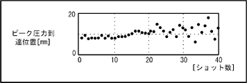
- 8A and 8B show an example of statistical data of the peak pressure arrival position.
- FIG. 8A is a graph in which the feature amount for each shot is plotted
- FIG. 8B is a graph in which statistical data calculated from the feature amount is plotted.
- the statistical condition (statistical condition No.
- the statistical data calculation unit 120 divides the feature amount of the peak pressure arrival position calculated for each shot into 10 shots and calculates the standard deviation, and uses the result as the statistical data of the peak pressure arrival position.
- the statistical data calculation unit 120 stores the statistical data calculated in this way in the statistical data storage unit 330 in association with the number of production (number of shots) produced by the injection molding machine 4.
- the operator may visually confirm the dispersion state of the feature amount plotted in FIG. 8A and select the statistical function.
- the regression analysis unit 130 is realized by executing a system program read from the ROM 12 by the CPU 11 included in the state determination device 1 shown in FIG. 1 and performing arithmetic processing mainly by the CPU 11 using the RAM 13 and the non-volatile memory 14. Will be done.
- the regression analysis unit 130 refers to the statistical data stored in the statistical data storage unit 330, performs regression analysis on the statistical data related to each physical quantity, and calculates a coefficient of a predetermined regression equation.
- the regression analysis unit 130 stores the calculated coefficient of the regression equation in the regression coefficient storage unit 340.
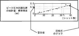
- FIG. 9 shows an example of a graph of the regression equation obtained by regression analysis of the statistical data of the peak pressure arrival position exemplified in FIG. 8B.
- the regression analysis unit 130 sets the target variable y as the statistic (standard deviation) of the peak pressure arrival position and the explanatory variable x as the number of production (number of shots), and sets the value estimated from the explanatory variable x and the objective variable.
- the variables a and b that minimize the error (estimation error) from y are calculated by the least squares method.
- the calculated coefficients a and b are stored in the regression coefficient storage unit 340.
- the predetermined regression equations include root regression equations, natural logistic regression equations, fractional regression equations, power multiplication regression equations, exponential regression equations, and modified exponential regression equations, depending on the trend of statistical changes. , Logistic regression equation, etc. may be used at any time.
- the operator visually confirms the dispersion state of the statistics plotted in FIG. 9, and the regression equation that matches the tendency of the change of the statistics (1 if it changes linearly). It may be a linear regression equation which is the following equation, an exponential regression equation which is an nth order equation when it changes in a curve, or another regression equation).
- the determination unit 140 is realized by executing a system program read from the ROM 12 by the CPU 11 included in the state determination device 1 shown in FIG. 1 and performing arithmetic processing mainly by the CPU 11 using the RAM 13 and the non-volatile memory 14. To.
- the determination unit 140 determines the timing at which each statistic reaches a predetermined warning value based on the regression equation whose coefficient is determined by the regression analysis unit 130.
- the warning value a test operation may be performed in advance to obtain a statistical value that prevents the injection molding machine 4 from performing a normal molding operation.
- the warning value of the standard deviation of the peak pressure arrival position is set to 6 mm
- the determination unit 140 is the production number (the production number) at which the value calculated from the regression equation reaches the warning value of 6.0 mm.
- the number of shots) x 1 is determined to be the timing for issuing a warning.
- the determination unit 140 outputs the determination result.
- the determination unit 140 may display and output the determination result to the display device 70. Further, the determination unit 140 may transmit and output the determination result to a higher-level device such as the control device 3 of the injection molding machine 4, the fog computer 6, or the cloud server 7 via the network 9.
- the timing at which the determination unit 140 issues the determination warning may be the number of shots produced by the injection molding machine 4 (number of shots, x 1 in the example of FIG. 9).
- the number of remaining production until the warning is reached (number of shots, in the example of FIG. 9, x 1-30 when 30 shots are currently performed) in view of the current production number (number of shots) of the injection molding machine 4.
- the number of production (number of shots) converted to the date and time or the remaining time is displayed based on the time related to one shot, the pace of the current injection operation, the cycle time, and the like. It may be displayed and output to the device 70.
- FIG. 10 shows, as an example of displaying and outputting the determination result by the determination unit 140, a warning display including the remaining production number (number of shots) until the warning value is reached and the date and time when the warning value is reached.
- the determination unit 140 calculates the degree of deviation indicating how much each of the latest statistics deviates from the regression equation based on the regression equation whose coefficient is determined by the regression analysis unit 130. Then, when the degree of deviation exceeds a predetermined threshold value, a warning to that effect is output. At this time, a plurality of predetermined threshold values may be provided.
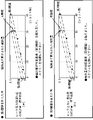
- FIG. 12 is an operation screen displayed on the display device 70, and is a diagram showing an example in which threshold values are provided above and below the regression equation.
- the dotted line shows a graph of a linear regression equation.
- the two broken lines indicate the positions indicating the positions separated from the graph of the linear regression equation by the first threshold value and the second threshold value, respectively.
- the difference from the value (estimated statistic) obtained by substituting the current number of shots for the regression equation related to is calculated as the degree of deviation.
- a warning to that effect is output.
- the warning when the degree of divergence exceeds the first threshold value (upward divergence) in the upward direction, the message “Statistics exceeds the judgment standard (first threshold value)” illustrated in FIG. "Please check” may be displayed on the operation screen, or if the degree of deviation exceeds the second threshold (downward deviation) in the downward direction, a message different from the first threshold may be displayed on the operation screen. Then, the operation of the injection molding machine may be stopped. In this way, different warnings can be output when the first threshold value is exceeded and when the second threshold value is exceeded.
- FIG. 13 is an operation screen displayed on the display device 70, and is a diagram showing an example in which a plurality of threshold values are set stepwise in the upward direction of the regression equation.
- the dotted line shows a graph of a linear regression equation.
- the two broken lines indicate the positions indicating the positions separated by the third threshold value and the fourth threshold value in the upward direction from the graph of the linear regression equation, respectively.
- the difference from the value (estimated statistic) obtained by substituting the current number of shots for the regression equation related to is calculated as the degree of deviation. Then, when the degree of deviation exceeds the third threshold value (the deviation of the first stage in the upward direction) but is equal to or less than the fourth threshold value (the deviation of the second stage in the upward direction), the operation of the injection molding machine is decelerated. However, if the fourth threshold value (deviation of the second step in the upward direction) is exceeded, different warnings are output so as to stop the operation of the injection molding machine. If there are multiple thresholds in the same direction of the regression equation, a warning can be output to impose a greater constraint on the injection molding machine for the larger thresholds.
- threshold values when a plurality of threshold values are provided stepwise in this way, three or more steps may be provided and the degree of deviation of each may be calculated and determined. Further, it may be combined with the above-mentioned case where the threshold value is set in each of the vertical directions.
- the statistic estimated based on the regression equation functions as a reference for determining the normality or abnormality of the statistic calculated from the data related to the physical quantity acquired from the injection molding machine 4 in the current operating state. After the maintenance of the injection molding machine 4, the screw is worn and the belt is worn as the molding operation is repeated. Therefore, the statistic calculated based on the physical quantity acquired from the injection molding machine 4 gradually changes as the molding operation is performed immediately after the maintenance, even if the molding operation is normally performed. In the present invention, this change is obtained as a regression equation and used as a reference when detecting a sudden abnormality.
- normality or abnormality is determined by the degree of deviation from the reference value fixedly set for the statistic, but in the present invention, the change tendency of the statistic is obtained as a regression equation, and this regression equation is used.
- the normality or abnormality of the molding operation is judged by the degree of deviation from.
- the regression equation reflects the statistics obtained from the molding operations that were repeated in the past. That is, since the process of progressing the state such as screw wear and belt wear caused by repeated molding operations is reflected in the regression equation, the judgment should be made in consideration of the transition of the molding state due to actual molding. Make it possible. As a result, it is possible to accurately determine whether the injection molding machine 4 is normal or abnormal according to the current state of the injection molding machine 4.
- the state determination device 1 can grasp the production number and the date and time when a production abnormality is predicted to occur in the future based on the time series data obtained by the actual molding. Become.
- the operator should be notified that a sudden abnormality has occurred, or the injection molding machine should be stopped to ensure a safe condition.
- planned preventive maintenance can be carried out, the frequency of periodic inspection work that has been conventionally performed is reduced, the burden on the operator is reduced, and work efficiency and operation rate are improved.
- the operator can take measures to continue production (eg, grease greasing of moving parts, adjust operating conditions, etc.) before an abnormality occurs, and minimize downtime.
- the operating rate can be improved.
- the cost can be reduced. Since these judgments are estimated based on the numerical information obtained by the actual molding, not the judgment of the presence or absence of an abnormality based on the experience and intuition of the operator, stable judgment with reproducibility is realized.
- the determination unit 140 in the above-described embodiment not only outputs the determination result, but also performs injection molding when the determined production number or date and time is reached, or when the degree of deviation exceeds a predetermined threshold value.
- the operation of the machine 4 may be stopped, decelerated, or a signal or the like for limiting the drive torque of the prime mover for driving the injection molding machine 4 may be output. With such a configuration, the operation of the injection molding machine 4 can be automatically stopped before the number of molding defects increases, or a safe standby state can be set to prevent the injection molding machine 4 from being damaged.
- a plurality of injection molding machines 4 are connected to each other via a network 9, data is acquired from the plurality of injection molding machines and the molding state of each injection molding machine is determined by one state determination device 1.
- the determination may be made, or the state determination device 1 may be arranged on each control device provided in the plurality of injection molding machines, and the molding state of each injection molding machine may be determined in each state of the injection molding machine.
- the determination device may be used for determination.
- Control device Control device 4 Injection molding machine 5 Sensor 6 Fog computer 7 Cloud server 9 Network 11 CPU 12 ROM 13 RAM 14 Non-volatile memory 15, 17, 18, 20 Interface 22 Bus 70 Display device 71 Input device 72 External device 100 Data acquisition unit 110 Feature amount calculation unit 120 Statistical data calculation unit 130 Regression analysis unit 140 Judgment unit 300 Acquisition data storage unit 310 Feature storage unit 320 Statistical condition storage unit 330 Statistical data storage unit 340 Regression coefficient storage unit
Landscapes
- Engineering & Computer Science (AREA)
- Manufacturing & Machinery (AREA)
- Mechanical Engineering (AREA)
- Physics & Mathematics (AREA)
- General Physics & Mathematics (AREA)
- Automation & Control Theory (AREA)
- Human Computer Interaction (AREA)
- Artificial Intelligence (AREA)
- Evolutionary Computation (AREA)
- Mathematical Physics (AREA)
- Injection Moulding Of Plastics Or The Like (AREA)
Abstract
Un dispositif de détermination d'état 1 comprend : une unité d'acquisition de données 100 qui acquiert un nombre de production et des données relatives à une quantité physique prédéterminée, en tant que données indiquant un état associé à une machine de moulage par injection 4 ; une unité de calcul de quantité de caractéristiques 110 qui calcule une quantité de caractéristiques indiquant une caractéristique de l'état en fonction des données ; une unité de calcul de données statistiques 120 qui calcule, sur la base de la quantité de caractéristiques calculée, une quantité de statistiques en tant que données statistiques selon une condition statistique comprenant une fonction statistique pour calculer une quantité de statistiques prédéterminée à partir d'une quantité de caractéristiques prédéterminée ; une unité d'analyse de régression 130 qui effectue une analyse de régression à l'aide d'une formule de régression prédéterminée sur la base des données statistiques et du nombre de production et qui calcule un coefficient de la formule de régression prédéterminée ; et une unité de détermination 140 qui calcule un degré de déviation entre la dernière quantité de statistiques et la formule de régression obtenue et qui détermine si le degré de déviation est supérieur à une valeur de seuil prédéterminée.
Priority Applications (4)
| Application Number | Priority Date | Filing Date | Title |
|---|---|---|---|
| US18/246,514 US20230367293A1 (en) | 2020-10-05 | 2021-10-04 | State determination device and state determination method |
| CN202180066719.3A CN116234674A (zh) | 2020-10-05 | 2021-10-04 | 状态判定装置及状态判定方法 |
| JP2022555454A JP7495513B2 (ja) | 2020-10-05 | 2021-10-04 | 状態判定装置及び状態判定方法 |
| DE112021005249.7T DE112021005249T5 (de) | 2020-10-05 | 2021-10-04 | Zustandsbestimmungsvorrichtung und zustandsbestimmungsverfahren |
Applications Claiming Priority (2)
| Application Number | Priority Date | Filing Date | Title |
|---|---|---|---|
| JP2020-168772 | 2020-10-05 | ||
| JP2020168772 | 2020-10-05 |
Publications (1)
| Publication Number | Publication Date |
|---|---|
| WO2022075242A1 true WO2022075242A1 (fr) | 2022-04-14 |
Family
ID=81126007
Family Applications (1)
| Application Number | Title | Priority Date | Filing Date |
|---|---|---|---|
| PCT/JP2021/036559 Ceased WO2022075242A1 (fr) | 2020-10-05 | 2021-10-04 | Dispositif de détermination d'état et procédé de détermination d'état |
Country Status (5)
| Country | Link |
|---|---|
| US (1) | US20230367293A1 (fr) |
| JP (1) | JP7495513B2 (fr) |
| CN (1) | CN116234674A (fr) |
| DE (1) | DE112021005249T5 (fr) |
| WO (1) | WO2022075242A1 (fr) |
Cited By (1)
| Publication number | Priority date | Publication date | Assignee | Title |
|---|---|---|---|---|
| CN117655315A (zh) * | 2024-02-02 | 2024-03-08 | 山东中力高压阀门股份有限公司 | 一种阀门浇筑过程包内铁液温度实时监测系统 |
Families Citing this family (1)
| Publication number | Priority date | Publication date | Assignee | Title |
|---|---|---|---|---|
| CN115452116A (zh) * | 2022-08-31 | 2022-12-09 | 安徽精益数智科技有限公司 | 基于振动信息的产品状态分析方法、系统、设备和介质 |
Citations (5)
| Publication number | Priority date | Publication date | Assignee | Title |
|---|---|---|---|---|
| JP2005280015A (ja) * | 2004-03-29 | 2005-10-13 | Mitsubishi Electric Corp | 射出成形機の制御装置 |
| JP2007196480A (ja) * | 2006-01-25 | 2007-08-09 | Nissei Plastics Ind Co | 成形機のデータ処理方法及び装置 |
| JP2009045904A (ja) * | 2007-08-22 | 2009-03-05 | Fanuc Ltd | スクリュー回転トルク監視機能を備えた射出成形機 |
| JP2020044836A (ja) * | 2018-09-14 | 2020-03-26 | 株式会社名機製作所 | 射出成形機、射出成形機の状態報知システム、射出成形機の状態報知方法 |
| JP2020052821A (ja) * | 2018-09-27 | 2020-04-02 | 株式会社ジェイテクト | 劣化判定装置および劣化判定システム |
Family Cites Families (4)
| Publication number | Priority date | Publication date | Assignee | Title |
|---|---|---|---|---|
| JP2862881B2 (ja) | 1988-10-14 | 1999-03-03 | ファナック株式会社 | 成形品の良否判別基準値自動設定方法及び装置 |
| JPH06231327A (ja) | 1993-01-28 | 1994-08-19 | Konica Corp | 成形不良自動判別装置 |
| JP3546951B2 (ja) | 2000-09-08 | 2004-07-28 | 住友重機械工業株式会社 | 射出成形機の製品良否判別方法 |
| JP2003039519A (ja) | 2001-05-25 | 2003-02-13 | Toshiba Mach Co Ltd | 射出成形機におけるモニタリング方法 |
-
2021
- 2021-10-04 WO PCT/JP2021/036559 patent/WO2022075242A1/fr not_active Ceased
- 2021-10-04 DE DE112021005249.7T patent/DE112021005249T5/de not_active Withdrawn
- 2021-10-04 US US18/246,514 patent/US20230367293A1/en not_active Abandoned
- 2021-10-04 CN CN202180066719.3A patent/CN116234674A/zh not_active Withdrawn
- 2021-10-04 JP JP2022555454A patent/JP7495513B2/ja active Active
Patent Citations (5)
| Publication number | Priority date | Publication date | Assignee | Title |
|---|---|---|---|---|
| JP2005280015A (ja) * | 2004-03-29 | 2005-10-13 | Mitsubishi Electric Corp | 射出成形機の制御装置 |
| JP2007196480A (ja) * | 2006-01-25 | 2007-08-09 | Nissei Plastics Ind Co | 成形機のデータ処理方法及び装置 |
| JP2009045904A (ja) * | 2007-08-22 | 2009-03-05 | Fanuc Ltd | スクリュー回転トルク監視機能を備えた射出成形機 |
| JP2020044836A (ja) * | 2018-09-14 | 2020-03-26 | 株式会社名機製作所 | 射出成形機、射出成形機の状態報知システム、射出成形機の状態報知方法 |
| JP2020052821A (ja) * | 2018-09-27 | 2020-04-02 | 株式会社ジェイテクト | 劣化判定装置および劣化判定システム |
Cited By (2)
| Publication number | Priority date | Publication date | Assignee | Title |
|---|---|---|---|---|
| CN117655315A (zh) * | 2024-02-02 | 2024-03-08 | 山东中力高压阀门股份有限公司 | 一种阀门浇筑过程包内铁液温度实时监测系统 |
| CN117655315B (zh) * | 2024-02-02 | 2024-04-23 | 山东中力高压阀门股份有限公司 | 一种阀门浇筑过程包内铁液温度实时监测系统 |
Also Published As
| Publication number | Publication date |
|---|---|
| JP7495513B2 (ja) | 2024-06-04 |
| JPWO2022075242A1 (fr) | 2022-04-14 |
| DE112021005249T5 (de) | 2023-07-20 |
| US20230367293A1 (en) | 2023-11-16 |
| CN116234674A (zh) | 2023-06-06 |
Similar Documents
| Publication | Publication Date | Title |
|---|---|---|
| JP5746128B2 (ja) | 保守部品の交換時期判断機能を有する工作機械 | |
| US20200272125A1 (en) | Machining defect occurrence prediction system for machine tool | |
| JP2020066178A (ja) | 状態判定装置及び状態判定方法 | |
| CN110920009B (zh) | 状态判定装置以及状态判定方法 | |
| JP2020128014A (ja) | 状態判定装置及び状態判定方法 | |
| WO2022075181A1 (fr) | Dispositif de détermination d'état et procédé de détermination d'état | |
| WO2022075242A1 (fr) | Dispositif de détermination d'état et procédé de détermination d'état | |
| WO2022075224A1 (fr) | Appareil de détermination d'état et procédé de détermination d'état | |
| CN116238176A (zh) | 一种人造石英石板原料配置控制系统 | |
| JP7311387B2 (ja) | 射出成形機管理支援装置及び射出成形機 | |
| CN110962315B (zh) | 状态判定装置以及状态判定方法 | |
| WO2022075244A1 (fr) | Dispositif de détermination d'état et procédé de détermination d'état | |
| JP7011106B1 (ja) | 状態判定装置及び状態判定方法 | |
| WO2022054782A1 (fr) | Dispositif de détermination d'état et procédé de détermination d'état | |
| WO2023026419A1 (fr) | Dispositif de commande et procédé de commande | |
| JP7184997B2 (ja) | 状態判定装置及び状態判定方法 | |
| JP2012035553A (ja) | 射出成形機の点検システム | |
| CN117389215A (zh) | 用于将过程状态的稳定性可视化的方法和设备和生产设施 | |
| WO2023026411A1 (fr) | Dispositif de détermination d'état et procédé de détermination d'état | |
| WO2024057461A1 (fr) | Dispositif de détermination et procédé de détermination | |
| EP4403334A1 (fr) | Système et procédé de commande d'une ligne d'extrusion de matières plastiques mélangées | |
| US20230311382A1 (en) | Display device for injection molding, injection molding machine, and management device for injection molding | |
| WO2024057416A1 (fr) | Dispositif de commande et procédé de commande | |
| WO2024004106A1 (fr) | Système et procédé de détermination | |
| WO2024089851A1 (fr) | Dispositif de détermination et procédé de détermination |
Legal Events
| Date | Code | Title | Description |
|---|---|---|---|
| 121 | Ep: the epo has been informed by wipo that ep was designated in this application |
Ref document number: 21877541 Country of ref document: EP Kind code of ref document: A1 |
|
| ENP | Entry into the national phase |
Ref document number: 2022555454 Country of ref document: JP Kind code of ref document: A |
|
| 122 | Ep: pct application non-entry in european phase |
Ref document number: 21877541 Country of ref document: EP Kind code of ref document: A1 |