WO2022075484A1 - プラグ、ダウンホールツールおよび坑井処理方法 - Google Patents
プラグ、ダウンホールツールおよび坑井処理方法 Download PDFInfo
- Publication number
- WO2022075484A1 WO2022075484A1 PCT/JP2021/037498 JP2021037498W WO2022075484A1 WO 2022075484 A1 WO2022075484 A1 WO 2022075484A1 JP 2021037498 W JP2021037498 W JP 2021037498W WO 2022075484 A1 WO2022075484 A1 WO 2022075484A1
- Authority
- WO
- WIPO (PCT)
- Prior art keywords
- plug
- resin molded
- well
- molded body
- opening
- Prior art date
- Legal status (The legal status is an assumption and is not a legal conclusion. Google has not performed a legal analysis and makes no representation as to the accuracy of the status listed.)
- Ceased
Links
Images


Classifications
-
- E—FIXED CONSTRUCTIONS
- E21—EARTH OR ROCK DRILLING; MINING
- E21B—EARTH OR ROCK DRILLING; OBTAINING OIL, GAS, WATER, SOLUBLE OR MELTABLE MATERIALS OR A SLURRY OF MINERALS FROM WELLS
- E21B33/00—Sealing or packing boreholes or wells
- E21B33/10—Sealing or packing boreholes or wells in the borehole
- E21B33/12—Packers; Plugs
-
- C—CHEMISTRY; METALLURGY
- C08—ORGANIC MACROMOLECULAR COMPOUNDS; THEIR PREPARATION OR CHEMICAL WORKING-UP; COMPOSITIONS BASED THEREON
- C08K—Use of inorganic or non-macromolecular organic substances as compounding ingredients
- C08K5/00—Use of organic ingredients
- C08K5/16—Nitrogen-containing compounds
- C08K5/29—Compounds containing one or more carbon-to-nitrogen double bonds
-
- E—FIXED CONSTRUCTIONS
- E21—EARTH OR ROCK DRILLING; MINING
- E21B—EARTH OR ROCK DRILLING; OBTAINING OIL, GAS, WATER, SOLUBLE OR MELTABLE MATERIALS OR A SLURRY OF MINERALS FROM WELLS
- E21B33/00—Sealing or packing boreholes or wells
- E21B33/10—Sealing or packing boreholes or wells in the borehole
- E21B33/12—Packers; Plugs
- E21B33/1208—Packers; Plugs characterised by the construction of the sealing or packing means
-
- E—FIXED CONSTRUCTIONS
- E21—EARTH OR ROCK DRILLING; MINING
- E21B—EARTH OR ROCK DRILLING; OBTAINING OIL, GAS, WATER, SOLUBLE OR MELTABLE MATERIALS OR A SLURRY OF MINERALS FROM WELLS
- E21B33/00—Sealing or packing boreholes or wells
- E21B33/10—Sealing or packing boreholes or wells in the borehole
- E21B33/12—Packers; Plugs
- E21B33/128—Packers; Plugs with a member expanded radially by axial pressure
-
- E—FIXED CONSTRUCTIONS
- E21—EARTH OR ROCK DRILLING; MINING
- E21B—EARTH OR ROCK DRILLING; OBTAINING OIL, GAS, WATER, SOLUBLE OR MELTABLE MATERIALS OR A SLURRY OF MINERALS FROM WELLS
- E21B33/00—Sealing or packing boreholes or wells
- E21B33/10—Sealing or packing boreholes or wells in the borehole
- E21B33/12—Packers; Plugs
- E21B33/129—Packers; Plugs with mechanical slips for hooking into the casing
-
- E—FIXED CONSTRUCTIONS
- E21—EARTH OR ROCK DRILLING; MINING
- E21B—EARTH OR ROCK DRILLING; OBTAINING OIL, GAS, WATER, SOLUBLE OR MELTABLE MATERIALS OR A SLURRY OF MINERALS FROM WELLS
- E21B33/00—Sealing or packing boreholes or wells
- E21B33/10—Sealing or packing boreholes or wells in the borehole
- E21B33/13—Methods or devices for cementing, for plugging holes, crevices or the like
- E21B33/134—Bridging plugs
-
- C—CHEMISTRY; METALLURGY
- C08—ORGANIC MACROMOLECULAR COMPOUNDS; THEIR PREPARATION OR CHEMICAL WORKING-UP; COMPOSITIONS BASED THEREON
- C08G—MACROMOLECULAR COMPOUNDS OBTAINED OTHERWISE THAN BY REACTIONS ONLY INVOLVING UNSATURATED CARBON-TO-CARBON BONDS
- C08G63/00—Macromolecular compounds obtained by reactions forming a carboxylic ester link in the main chain of the macromolecule
- C08G63/02—Polyesters derived from hydroxycarboxylic acids or from polycarboxylic acids and polyhydroxy compounds
- C08G63/06—Polyesters derived from hydroxycarboxylic acids or from polycarboxylic acids and polyhydroxy compounds derived from hydroxycarboxylic acids
-
- C—CHEMISTRY; METALLURGY
- C08—ORGANIC MACROMOLECULAR COMPOUNDS; THEIR PREPARATION OR CHEMICAL WORKING-UP; COMPOSITIONS BASED THEREON
- C08K—Use of inorganic or non-macromolecular organic substances as compounding ingredients
- C08K5/00—Use of organic ingredients
- C08K5/16—Nitrogen-containing compounds
- C08K5/34—Heterocyclic compounds having nitrogen in the ring
- C08K5/3442—Heterocyclic compounds having nitrogen in the ring having two nitrogen atoms in the ring
-
- C—CHEMISTRY; METALLURGY
- C08—ORGANIC MACROMOLECULAR COMPOUNDS; THEIR PREPARATION OR CHEMICAL WORKING-UP; COMPOSITIONS BASED THEREON
- C08L—COMPOSITIONS OF MACROMOLECULAR COMPOUNDS
- C08L101/00—Compositions of unspecified macromolecular compounds
- C08L101/16—Compositions of unspecified macromolecular compounds the macromolecular compounds being biodegradable
Definitions
- the present invention relates to a plug, a downhole tool and a well processing method.
- Well processing operations to recover hydrocarbon resources from the ground include, for example, fracturing and cleaning of wells.
- fracturing it is necessary to use a downhole tool or plug to block the flow of fluid in the well.
- the flow path of the cleaning fluid is lowered so that the cleaning fluid does not mix before and after cleaning during cleaning. Must be isolated with a hole tool.
- downhole tools need to be removed promptly by some method after the well treatment.
- the downhole tool or plug is required to be able to hold the seal for a predetermined period of time.
- Patent Document 1 discloses a method for treating a well using particles of a degradable material containing a stabilizer.
- Patent Document 2 discloses that when the acid group concentration of the resin is low, the decomposition of the resin is suppressed, and when the acid group concentration is high, the decomposition of the resin is promoted.
- Patent Document 3 discloses a molded product of a polyglycolic acid resin in which the rate of thickness reduction in water is constant with respect to time.
- Patent Document 4 discloses a treatment method using a tool including a plug having a corrosive property in the electrolyte.
- the prior art as described above is not a technique for decomposing a molded product having a thickness sufficient to withstand the pressure during fracture in water. Furthermore, the prior art documents as described above do not disclose specific decomposition retarders and compositions that have the effect of slowing the rate of thickness reduction. Further, since the hydrolysis reaction rate of polyglycolic acid is faster as the surrounding temperature is higher, there is a problem that the plug containing the polyglycolic acid member cannot hold the sealing in the well at a high temperature for a desired period. Further, in plugs containing corrosive metal members, the rate of corrosion strongly depends on the salt (electrolyte) concentration in the fluid, and the corrosion is slow in a fluid with a low salt concentration or in water. Therefore, the plug including the corrosive metal member has a problem that the sealing is not released even after the target period has passed.
- an object of the present invention is to provide a plug capable of holding a seal for a predetermined period even in a fluid or water having a high temperature and a low salt concentration. ..
- the plug according to the present invention contains a polyglycolic acid and a cyclic carbodiimide compound, and is formed from a polyglycolic acid resin composition having a carbodiimide group concentration of 15 eq / t or more.
- a plug provided with a body or composed of the resin molded body for temporarily obstructing the flow of fluid in a well.
- the downhole tool according to the present invention includes a tubular main body and the above-mentioned plug, and the above-mentioned tubular main body has an opening for communicating inside and outside thereof on its peripheral surface, and the above-mentioned plug has the above-mentioned opening. It is engaged with the tubular body so as to close the portion.
- the well treatment method according to the present invention uses the above-mentioned plug to temporarily seal at least one or more areas of the well and the downhole tool, and the above-mentioned resin molded body of the above-mentioned plug. Disassembling includes removing the seal and changing the flow path of the fluid in the above region.
- the above-mentioned plug is installed in the well to obstruct the flow of the fluid in the well, and the resin molded body is decomposed to restore the flow of the above-mentioned fluid.
- the well processing method according to the present invention has a first opening at the start end and a second opening at the end, and further has a third opening between the start end and the end.
- the fluid is sprayed into the well to clean the well, and after cleaning, the resin molded body of the plug is decomposed to be inside and outside the downhole tool through the third opening. Includes enabling fluid flow.
- the sealing can be maintained for a predetermined period even in a fluid or water having a high temperature and a low salt concentration.
- Plug A plug refers to a member or device used to temporarily impede the flow of fluid in a well. Its form is not limited as long as it is used to temporarily impede the flow of fluid in the well, and may be, for example, a ball, dirt, disc, screw, flak plug, bridge plug or packer.
- the plug according to the present embodiment includes a resin molded body formed of a polyglycolic acid resin composition, or is composed of a resin molded body formed of a polyglycolic acid resin composition.
- a resin molded body formed of a polyglycolic acid resin composition
- a plug including a resin molded body formed from a polyglycolic acid resin composition
- the resin molded body is decomposed to eliminate the obstruction of fluid flow, it can be applied to a specific component. It is not limited to use. Details of specific examples of plugs will be described later.
- the shape of the resin molded body is not particularly limited, and it is appropriately designed according to the plug to be applied or the member in the plug.
- the resin molded body used for the plug of the present embodiment is formed from a polyglycolic acid resin composition.
- the polyglycolic acid resin composition in the present embodiment contains polyglycolic acid and a cyclic carbodiimide compound. Further, the concentration of the carbodiimide group in the polyglycolic acid resin composition is 15 eq / t or more.
- the term "cyclic carbodiimide compound" as used herein refers to a cyclic carbodiimide compound that has not reacted with polyglycolic acid, unless otherwise specified.
- the content of the cyclic carbodiimide compound is preferably 0.4% by mass or more in the polyglycolic acid resin composition.
- the content of the cyclic carbodiimide compound can be appropriately adjusted according to the sealing retention period and the like desired for the resin molded product formed from the composition. From the viewpoint of more reliably reducing the thickness reduction rate of the molded product, the content of the cyclic carbodiimide compound is more preferably 0.7% by mass or more, further preferably 1% by mass or more. Further, from the viewpoint of stable melt-kneading of the polyglycolic acid resin composition, the content of the cyclic carbodiimide compound is preferably 30% by mass or less, more preferably 25% by mass or less.
- the polyglycolic acid used in the polyglycolic acid resin composition in the present embodiment is a polymer containing a repeating unit represented by-(-O-CH 2 -CO-)-.
- the polyglycolic acid may be a homopolymer of glycolic acid or a copolymer of glycolic acid and other monomer components.
- Other monomer components used in the copolymer include, for example, hydroxycarboxylic acids such as L-lactic acid, D-lactic acid, 3-hydroxybutanoic acid and 1-hydroxyhexanoic acid, 1,4-butanediol and succinic acid.
- Ester compounds composed of diols and dicarboxylic acids such as condensates and condensates of 1,4-butanediol and adipic acid, cyclic esters and lactones produced by intramolecular condensation of the other monomer components described above, and Cyclic carbonates such as trimethylene carbonate can be mentioned.
- polyglycolic acid is a copolymer of glycolic acid and other monomer components
- the constituent unit derived from glycolic acid is 70 mol% or more, preferably 80 mol% or more, and more preferably 90 mol% or more. Is.
- the melt viscosity of the copolymer is lower than the melt viscosity of a glycolic acid homopolymer having the same molecular weight as the copolymer. Is preferable. If the copolymer has such a melt viscosity, it is not necessary to raise the melt temperature in the case of solidification extrusion molding or injection molding using the polyglycolic acid resin composition, and the molecular weight of the polyglycolic acid can be reduced. Since it can be suppressed, the desired high-strength downhole tool member can be satisfactorily obtained.
- the weight average molecular weight of the homopolymer is preferably more than 20,000.
- the weight average molecular weight of the homopolymer is more than 20,000, the water vapor barrier property of polyglycolic acid is guaranteed. As a result, the permeation of water into the resin molded body used for the plug can be delayed, so that the plug can be prevented from being bulk-decomposed.
- the weight average molecular weight of the polyglycolic acid homopolymer is preferably 50,000 or more, more preferably 70,000 or more, still more preferably 150,000 or more.
- the upper limit of the weight average molecular weight of the polyglycolic acid homopolymer is not particularly limited, but is usually preferably 500,000 or less, more preferably 300,000 or less, from the viewpoint of enabling solidification extrusion molding or injection molding.
- the terminal of polyglycolic acid is capped with a cyclic carbodiimide compound.
- the terminal of polyglycolic acid is capped by the cyclic carbodiimide compound is intended to have a structure obtained by reacting the carboxyl group at the terminal of polyglycolic acid with the cyclic carbodiimide compound. are doing. If the ends of the polyglycolic acid are capped by the cyclic carbodiimide compound, it does not necessarily have to be capped at all the polyglycolic acid ends.
- the concentration of the carboxyl group terminal of the polyglycolic acid contained in the polyglycolic acid resin composition is preferably 10 eq / t or less. It is more preferably 8 eq / t or less, and further preferably 6 eq / t or less.
- the lower limit of the concentration of the carboxyl group terminal of polyglycolic acid is not particularly limited, but the concentration is usually about 0.1 eq / t or more.
- the concentration of the carboxyl group terminal of polyglycolic acid contained in the polyglycolic acid resin composition can be calculated by titration using a neutralization reaction. Specifically, the following method can be given as an example. That is, the polyglycolic acid resin composition is dissolved in a solvent such as DMSO, a pH indicator is added, and the alkaline solution is dropped while observing the color change of the mixed solution. This is a method in which the dropping is completed when the color of the mixed solution does not change, and the carboxyl group concentration is calculated from the dropping amount of the alkaline solution.
- a DMSO solution of 1,8-diazabicyclo [5,4,0] undec-7-ene can be used as the alkaline solution.
- the substrate concentration of the alkaline solution can be appropriately adjusted according to the carboxyl group terminal concentration of the polyglycolic acid.
- the same compound as the cyclic carbodiimide compound contained in the polyglycolic acid resin composition can be typically used, but it does not necessarily have to be the same compound.
- polyglycolic acid Since the end of polyglycolic acid is capped with a cyclic carbodiimide compound, decomposition of polyglycolic acid can be suppressed in a well environment.
- the cyclic carbodiimide compound contained in the polyglycolic acid resin composition in the present embodiment is a compound having a cyclic structure in which the primary nitrogen and the secondary nitrogen of the carbodiimide group are bonded by a bonding group.
- the cyclic carbodiimide compound can be represented by, for example, the following formula (I).
- R represents one or more divalent linking groups selected from the group consisting of aliphatic groups, alicyclic groups and aromatic groups. Further, in the formula (I), R may contain a heteroatom. Examples of heteroatoms include oxygen (O), nitrogen (N), sulfur (S) and phosphorus (P). Further, R may include a ring structure, which may include a carbodiimide structure.
- the type and number of atoms constituting the main chain of the cyclic structure can be appropriately determined within the range in which the effects of the present embodiment can be obtained. For example, the number of atoms directly constituting the cyclic structure is preferably 8 or more, and more preferably 10 or more. The number of the atoms is preferably 50 or less, more preferably 20 or less.
- R may further have a monovalent substituent within the range in which the effect of the present embodiment can be obtained. More specifically, R is an aliphatic group having 2 to 4 valences of 1 to 20 carbon atoms, an alicyclic group having 2 to 4 valences of 3 to 20 carbon atoms, and an aromatic group having 2 to 4 valences of 5 to 15 carbon atoms. It may be a family group or a combination thereof. Examples of such combinations include an alkylene-arylene group in which an alkylene group and an arylene group are bonded.
- Examples of the aliphatic group in R include an alkylene group having 1 to 20 carbon atoms, an alkanetriyl group having 1 to 20 carbon atoms and an alkanetetrayl group having 1 to 20 carbon atoms.
- alkylene group examples include a methylene group, an ethylene group, a propylene group, a butylene group, a pentylene group, a hexylene group, a heptylene group, an octylene group, a nonylene group, a decylene group, a dodecylene group and a hexadecilene group.
- alcantriyl groups include methanetriyl group, ethanetriyl group, propanetriyl group, butantryyl group, pentanetriyl group, hexanetriyl group, heptanetriyl group, octantriyl group, nonantriyl group, decantryyl group, dodecantry. Includes yl and hexadecantryyl groups.
- alkanetetrayl groups include methanetetrayl group, ethanetetrayl group, propanetetrayl group, butanetetrayl group, pentanetetrayl group, hexanetetrayl group, heptanetetrayl group, octanetetrayl group, nonane. Includes tetrayl group, decanetetrayl group, dodecanetetrayl group and hexadecanetetrayl group.
- Examples of the alicyclic group in R include a cycloalkylene group having 3 to 20 carbon atoms, a cycloalkanetriyl group having 3 to 20 carbon atoms, and a cycloalkanetetrayl group having 3 to 20 carbon atoms.
- cycloalkylene groups include cyclopropylene group, cyclobutylene group, cyclopentylene group, cyclohexylene group, cycloheptylene group, cyclooctylene group, cyclononylene group, cyclodecylene group, cyclododecylene group and cyclohexadecylene group. Is done.
- cycloalkanetriyl groups include cyclopropanetriyl group, cyclobutanetriyl group, cyclopentanetriyl group, cyclohexanetriyl group, cycloheptanetriyl group, cyclooctanetriyl group, cyclononantryyl group, cyclo. Includes decantryyl groups, cyclododecanetriyl groups and cyclohexadecanetriyl groups.
- cycloalkanetetrayl groups include cyclopropanetetrayl group, cyclobutanetetrayl group, cyclopentanetetrayl group, cyclohexanetetrayl group, cycloheptanetetrayl group, cyclooctanetetrayl group, cyclononanetetrayl group, Cyclodecanetetrayl groups, cyclododecanetetrayl groups and cyclohexadecanetetrayl groups are included.
- Examples of the aromatic group in R include an arylene group having 5 to 15 carbon atoms, an arene triyl group having 5 to 15 carbon atoms, and an arene tetrayl group having 5 to 15 carbon atoms.
- the aromatic group may contain a hetero atom.
- arylene group examples include a phenylene group and a naphthalenediyl group.
- Examples of the arene triyl group (trivalent) include a benzenetriyl group and a naphthalenetriyl group.
- Examples of the arene tetrayl group include a benzenetetrayl group and a naphthalenetetrayl group.
- R may have include an alkyl group having 1 to 20 carbon atoms, an aryl group having 6 to 15 carbon atoms, a halogen atom, a nitro group, an amide group, a hydroxyl group, an ester group and an ether group. And aldehyde groups are included.
- cyclic carbodiimide compounds it is preferable to use a compound having only one carbodiimide group in one cyclic structure from the viewpoint of preventing deterioration of the working environment due to the odor peculiar to the isocyanate compound. This is because the cyclic carbodiimide having the structure does not release the compound having an isocyanate group even if it reacts with the carboxyl group at the terminal of polyglycolic acid.
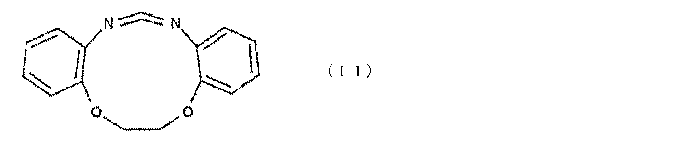
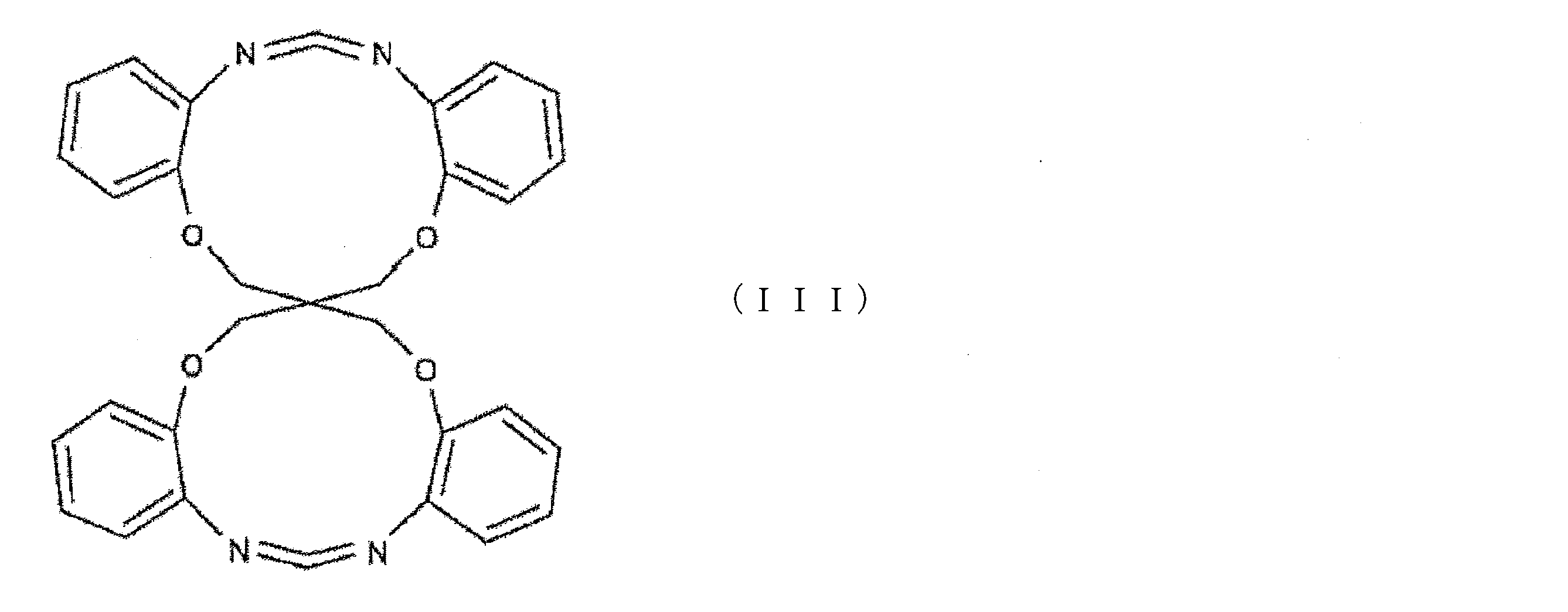
- Examples of the above-mentioned cyclic carbodiimide compound include, for example, a compound represented by the following formula (II) or the following formula (III).
- the polyglycolic acid resin composition may contain, for example, a derivative of the cyclic carbodiimide compound produced by reacting with the carboxyl group terminal of polyglycolic acid.
- the carbodiimide group contained in the polyglycolic acid resin composition has the structure of the following formula (IV).
- the concentration of the carbodiimide group in the polyglycolic acid resin composition according to the present embodiment is 15 eq / t or more.
- the concentration can be appropriately designed according to the sealing holding time required for the resin molded product of the present embodiment.
- the concentration is preferably 18 eq / t or more, more preferably 30 eq / t or more, and more preferably 50 eq / t or more. Is even more preferable.
- the concentration is preferably 900 eq / t or less, more preferably 800 eq / t or less, and 650 eq / t. The following is more preferable.
- concentration of the carbodiimide group is within this range, it is possible to realize a plug capable of holding the seal for a desired period in a high temperature environment.
- the concentration of the carbodiimide group terminal contained in the polyglycolic acid resin composition can be calculated, for example, by 1 H NMR measurement using dimethyl sulfone as a standard substance.
- the polyglycolic acid resin composition according to the present embodiment contains a heat stabilizer, an antioxidant, an impact-resistant modifier, a cross-linking agent, and an organic substance as long as the desired effect of the plug according to the present embodiment is not lost.
- Other additives such as fillers, inorganic fillers, and colorants may be included.
- the hydrolysis of the polyglycolic acid contained in the composition is suppressed. Hydrolysis is suppressed as the content of the carbodiimide compound increases. This is because water also reacts with carbodiimide groups, so the more carbodiimide groups are contained in the polyglycolic acid resin composition, the more water is consumed in the reaction with the carbodiimide groups, and as a result, it is involved in the hydrolysis of polyglycolic acid. This is because less water is used.
- the polyglycolic acid resin composition according to the present embodiment has a carbodiimide group concentration of 15 eq / t or more, so that the polyglycolic acid contained in the resin molded body formed from the composition is in a high temperature well environment. Hydrolysis can be moderately suppressed. Therefore, such a resin molded product can maintain the sealing for a desired period in a high temperature environment.
- "high temperature” is intended to be a temperature of 80 ° C. or higher.
- the thickness of the plug for obtaining the same sealing holding time is set to a resin molded product formed from a polyglycolic acid resin composition containing no cyclic carbodiimide compound. Can be smaller than. As a result, it is possible to increase the width and degree of freedom in the design of the downhole tool.
- the wall thickness of the tubular body can be reduced according to the thickness of the plug, a downhole
- the inner diameter of the tool can be increased.
- the application of the plug of the present embodiment can also contribute to an increase in the transport efficiency of such a fluid.
- the resin molded product according to the present embodiment can be produced by mixing polyglycolic acid and a cyclic carbodiimide compound and solidifying extrusion molding or injection molding of the mixture.
- the mixture may be a mixture of polyglycolic acid and a cyclic carbodiimide compound melt-kneaded and pelletized.
- the temperature is preferably 220 to 280 ° C., more preferably 230 to 260 ° C. from the viewpoint of suppressing thermal decomposition of polyglycolic acid.
- the amount of the cyclic carbodiimide compound added to the polyglycolic acid is preferably 2 parts by mass or more, more preferably 3 parts by mass or more, and further preferably 4 parts by mass or more with respect to 100 parts by mass of the polyglycolic acid.
- a part of the added cyclic carbodiimide compound is a terminal carboxyl of the polyglycolic acid. It reacts with the group and is used for capping polyglycolic acid.
- the concentration of the carbodiimide group in the finally obtained resin molded product can be adjusted to 15 eq / t or more. Further, it is also possible to adjust the content of the cyclic carbodiimide compound in the resin molded product to 0.4% by mass or more.
- the amount of the cyclic carbodiimide compound to be added it may be, for example, 30 parts by mass or less, and further 20 parts by mass or less.
- the temperature at the time of solidification extrusion molding or injection molding of the resin molded body is preferably 220 to 280 ° C, more preferably 230 to 260 ° C.
- the resin molded product according to the present embodiment includes a resin molded product formed from the polyglycolic acid resin composition or is composed of the resin molded product formed from the polyglycolic acid resin composition, the salt concentration is high. It also suitably decomposes in low fluids or water.
- the resin molded body according to the present embodiment is immersed in water, the molecular weight of the polyglycolic acid in the surface layer portion of the resin molded body is reduced by hydrolysis due to the water. As a result, the surface layer portion of the resin molded product becomes brittle.
- the polyglycolic acid having a reduced molecular weight permeates water, the polyglycolic acid is gradually hydrolyzed from the surface layer portion to the central portion of the resin molded body, so that the embrittlement of the resin molded body progresses.
- the reduced molecular weight polyglycolic acid is further reduced in molecular weight by further hydrolysis, the oligomer or glycolic acid produced as a hydrolysis product elutes into water, and as a result, the resin molded body loses its shape. In this way, the resin molded product is finally decomposed. By disassembling the resin molded body, the sealing by the resin molded body is released.
- the time from the time when the resin molded body is immersed in water to the time when the polyglycolic acid on the surface layer of the molded body is hydrolyzed and the thickness of the molded body starts to decrease is referred to as "decomposition lead”. It's called "time.”
- the resin molded product retains its shape immediately before being immersed in water until at least the decomposition lead time elapses after being immersed in water.
- embrittled portion is referred to as an embrittlement layer.
- the decomposition lead time when the resin molded body is immersed in water at 80 ° C. and the progress rate of embrittlement of the resin molded body depend on the hydrolysis rate of polyglycolic acid, and the desired sealing retention time. It can be adjusted as appropriate according to the above.
- “the rate of hydrolysis of polyglycolic acid and the rate of progress of embrittlement of the resin molded product” are simply referred to as "decomposition rate”.
- the preferable decomposition lead time when the resin molded product is immersed in water at 80 ° C. depends on the design of the downhole tool to which the resin molded product is applied, so it cannot be said unconditionally. However, from the viewpoint of prolonging the sealing holding time and keeping the volume of the resin molded body small, it is preferable that the decomposition lead time of the resin molded body is long. Keeping the volume of the resin molded body small is also preferable from the viewpoint of increasing the width and degree of freedom in the design of the downhole tool.
- the decomposition lead time may be, for example, 2 hours or more, more preferably 10 hours or more, and further preferably 16 hours or more. Further, in this case, the decomposition lead time is preferably 72 hours or less, more preferably 48 hours or less, and further preferably 40 hours or less.
- the decomposition lead time can be extended by increasing the content of the cyclic carbodiimide compound or the concentration of the carbodiimide group in the resin molded product. This is because the water molecules that come into contact with the resin molded body first react with the cyclic carbodiimide compound or the carbodiimide group, so that the hydrolysis of polyglycolic acid on the surface of the resin molded body is suppressed.
- the resin molded product according to the present embodiment when the resin molded product according to the present embodiment is immersed in water at 80 ° C. for 48 hours, a central portion and a surface layer portion having a weight average molecular weight smaller than that of the central portion are formed.
- the weight average molecular weight of the polyglycolic acid in the central portion of the resin molded product is 70,000 or more.
- the surface layer portion of the resin molded product has a weight average molecular weight of polyglycolic acid of 20,000 or less.
- the thickness of the central portion and the surface layer portion of the resin molded body after immersion depends on the total thickness of the resin molded body, but is as follows, for example. That is, when the thickness of the resin molded body is about 5 mm, the difference between the thickness of the central portion and the thickness of the resin molded body before immersion is preferably 0.1 mm or more, preferably 0.2 mm or more. Is more preferable, and 0.3 mm or more is further preferable. Further, the difference in thickness is preferably 2.0 mm or less, more preferably 1.9 mm or less, and further preferably 1.8 mm or less.
- the weight average molecular weight of polyglycolic acid decreases as hydrolysis progresses. Since the carboxyl group terminal of polyglycolic acid is acidic, it functions as a hydrolysis catalyst for ester bonds, so that the decomposition rates differ between the central portion and the surface layer portion of the resin molded body. Decomposition of the central portion and the surface layer portion can also be delayed by increasing the content of the cyclic carbodiimide compound or the concentration of the carbodiimide group in the resin molded product, as in the lead time.
- the progress rate of embrittlement of the resin molded product is defined as the thickness reduction rate.
- the thickness reduction rate is the rate at which the thickness of the non-brittled portion of the resin molded product decreases. Embrittlement progresses from the surface of the resin molded body toward the center, and the thickness of the non-embrittled portion decreases from the surface side. Therefore, the rate of embrittlement progress is positively correlated with the rate of thickness reduction.
- the resin molded product according to the present embodiment preferably has a thickness reduction rate of 0.1 ⁇ m / hr or more, more preferably 1 ⁇ m / hr or more, and 5 ⁇ m / hr after the decomposition lead time has elapsed in water at 80 ° C.
- the above is more preferable.
- the thickness reduction rate is preferably less than 64 ⁇ m / hr, more preferably less than 61 ⁇ m / hr, and even more preferably less than 50 ⁇ m / hr.
- the resin molded product according to this embodiment is formed of a polyglycolic acid resin composition. Since polyglycolic acid has a high water vapor barrier property, in order for water molecules to reach the center of the resin molded product, the water molecules must first pass through the embrittled layer formed by hydrolysis of the surface layer portion. As described above, in the resin molded product according to the present embodiment, the embrittlement does not proceed rapidly because the hydrolysis and embrittlement of the central portion do not occur until the surface layer portion is embrittled.
- the resin molded product according to the present embodiment contains a cyclic carbodiimide compound or a carbodiimide group. Since the water molecule that has passed through the embrittlement layer first reacts with the cyclic carbodiimide compound or the carbodiimide group, the diffusion of the water molecule is further suppressed. This further delays the progress of embrittlement.
- the resin molded product according to the present embodiment can delay hydrolysis and embrittlement even after the decomposition lead time has elapsed, so that the sealing holding time can be extended even under high temperature conditions.
- the sealing holding time by the resin molded body can be more preferably adjusted by adjusting the decomposition rate of each of the central portion and the surface layer portion.
- a method of immersing the molded product in preheated water to reduce the molecular weight of polyglycolic acid only in the surface layer portion, and using different polyglycolic acid resin compositions in the central portion and the surface layer portion can be mentioned.
- by adjusting the thickness and shape of the molded product or by appropriately combining these conditions it is possible to more preferably adjust the sealing holding time under high temperature conditions.
- the resin molded body according to the present embodiment retains the function as a plug for a target period, and after the period of time, decomposes at a suitable rate even in a fluid having a low salt concentration (for example, in water having a low salt concentration). Be advanced. As a result, it is possible to suppress the disassembly in order to maintain the function, and at the same time, it is possible to solve the problem that the sealing is not released even after the target period has elapsed.
- the resin molded body in the present embodiment preferably has a tensile strength of 80 MPa or more, more preferably 90 MPa or more, and more preferably 100 MPa or more, from the viewpoint of withstanding high pressure in the well and retaining the seal. Is even more preferable. Further, from the viewpoint of facilitating the molding process, the tensile strength is preferably 400 MPa or less, more preferably 370 MPa or less, and further preferably 350 MPa or less.
- the tensile strength of the resin molded product was measured by using a type 1A tensile test piece and pulling it at a speed of 50 mm / min in an environment of 23 ° C. in accordance with ISO527.
- the resin molded body in the present embodiment preferably has a compressive yield stress of 100 MPa or more, preferably 110 MPa or more, from the viewpoint of suppressing plastic deformation due to high pressure received in the well and maintaining the sealing. It is more preferably 120 MPa or more, and even more preferably 120 MPa or more. Further, from the viewpoint of facilitating the molding process, the compressive yield stress is preferably 450 MPa or less, more preferably 420 MPa or less, and further preferably 400 MPa or less.
- the compression yield point stress of the resin molded product was measured by using a 5 mm square cubic resin molded product and compressing it at a speed of 1 mm / min with a compression tester in an environment of 23 ° C. be.
- plug used by closing an opening for communicating the inside and outside of the tubular member provided on the peripheral surface of the tubular member inserted into the well.
- plugs can be, for example, balls, dirt, discs, screws and packers applied to downhole tools.
- a wash pipe for cleaning a well or stimulating a stratum before fracture can be mentioned.
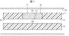
- FIG. 1 is a schematic cross-sectional view of a downhaul tool to which a plug according to the first aspect of the present invention is applied.
- the downhole tool 1 shown in FIG. 1 is inserted into a well and includes a cylindrical main body 14 as a cylindrical member.
- the downhole tool 1 has a first opening 16 at the start and a second opening 17 at the end, further having one or more third openings 18 between the start and the end. ..
- the third opening 18 is provided on the peripheral surface of the tubular main body 14 and is an opening for communicating the inside and outside of the tubular main body 14.
- a screw-shaped plug 11 is inserted into the third opening 18 so as to close the third opening 18, and the plug 11 is engaged with the third opening. As described above, the third opening 18 of the tubular main body 14 is sealed by the plug 11.
- the "starting edge" of the downhole tool refers to the end located on the entrance side of the well with the downhole tool set in the well, and when the downhole tool is inserted into the well. Refers to the end of the side that will be inserted last.
- the “end” is the end opposite to the start, and in the well, it refers to the end located at the back of the well when viewed from the entrance, when the downhole tool is inserted into the well. Refers to the end of the side that is inserted first.
- the plug 11 is a screw-shaped plug that closes an opening for communicating inside and outside of the tubular member provided on the peripheral surface of the tubular member.
- the plug 11 is composed of the resin molded body according to the present embodiment.
- the plug 11 Since the plug 11 is inserted into the third opening 18 of the tubular main body 14, the flow of fluid from the inside of the tubular main body 14 to the outside through the third opening 18 is obstructed. Then, when the plug 11 formed of the resin molded body is disassembled, the third opening 18 is released, and as a result, the tubular main body 14 is directed from the inside to the outside through the third opening 18. A fluid flow will occur.
- the size of the plug 11 may vary depending on the thickness of the tubular body 14 to be applied, but as an example, when the plug 11 is fitted in the tubular body 14, it is exposed to the outside of the tubular body 14.
- the shortest distance L1 between the first surface 121 of the plug 11 and the second surface 122 of the plug 11 exposed inside the tubular main body 14 may be 6 mm or more and 65 mm or less.
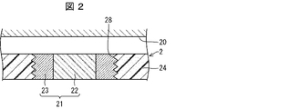
- FIG. 2 is an enlarged schematic view of a part of a cross section of a downhole tool to which a modification 1 of the first aspect of the plug according to the embodiment of the present invention is applied.
- the third opening 28 of the cylindrical main body 24 is sealed by the screw-shaped plug 21 as in the above-mentioned downhole tool 1.
- the plug 21 according to the modified example 1 is a plug that closes an opening for communicating the inside and outside of the tubular member provided on the peripheral surface of the tubular member, like the plug 11 described above.
- the plug 21 according to the first modification is composed of a main body portion 22 formed of the resin molded body according to the present embodiment and an annular molded body 23 formed of a non-decomposable material. , Different from plug 11.
- the annular molded body 23 in the first modification is an annular member having a thread on the outer peripheral surface that covers the periphery of the main body portion 22.
- the main body portion 22 is configured to be arranged inside the ring of the annular molded body 23.
- the annular molded body 23 in the first modification is formed of a non-degradable material such as SUS303 and SUS304.
- the "non-decomposable material” refers to a material whose weight or thickness does not easily decrease in a well environment.
- the annular molded body 23 is preferably made of a material that does not substantially lose weight or thickness for 30 days or more in the well.
- the plug 21 is inserted into the third opening 28 of the tubular main body 24, so that the fluid flowing from the inside of the tubular main body 24 to the outside through the third opening 28 The flow is obstructed. Then, by disassembling the main body 22 of the plug 21 made of the resin molded body, the third opening 28 is released, and as a result, the annular molding is performed through the third opening 28 in more detail. A fluid flow from the inside to the outside of the tubular main body 24 is generated through the inside of the ring of the body 23.
- the size of the main body 22 may be appropriately set by a person skilled in the art in the same manner as the size of the plug 11.
- FIG. 3 is an enlarged schematic view of a part of a cross section of a downhole tool to which a modification 2 of the first aspect of the plug according to the embodiment of the present invention is applied.
- the tubular main body 34 included in the downhole tool 3 in FIG. 3 is provided with a third opening 38 on the peripheral surface thereof to allow the inside and outside of the tubular main body 34 to communicate with each other.
- a plug 31 is engaged with the inside of the tubular main body 34.
- the plug 31, which is a modification 2 of the first aspect, is applied to a tubular member having an opening for communicating inside and outside on its peripheral surface, like the plug 11 of the first aspect described above. However, it differs from the plug 11 in that it is not inserted into the opening.
- the plug 31 of the second modification is engaged with the tubular member on the inside of the peripheral surface of the tubular member so as to close the opening.
- the third opening 38 is closed from the inside by the plug 31 engaging with the inside of the tubular main body 34. This hinders the flow of fluid from the inside of the tubular body 34 to the outside through the third opening 38.
- the portion formed by the resin molded body of the plug 21 is disassembled, so that the third opening 38 is exposed, and the fluid flowing from the inside to the outside of the tubular main body 34 through the third opening 38. Will occur.
- FIG. 4 is a schematic cross-sectional view of a downhole plug at a predetermined position in a well according to an embodiment of the present invention. Note that FIG. 4 shows only one of the cross sections symmetrical with respect to the axis of the downhole plug.
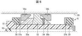
- the downhole plug 5 shown in FIG. 4 has a mandrel 51 corresponding to a tubular member, a ball 53, and a center element 52, a socket 54, cones 55a and 55b, and a slip 56a attached so as to surround the outer peripheral surface of the mandrel 51. And 56b, equalizer rings 57a and 57b, load ring 58, and bottom 59.
- the downhole plug 5 has a cylindrical shape as a whole.
- the mandrel 51 functions as a center pole that supports other members (hereinafter, side parts) arranged on the outer periphery of the mandrel 51, and as a receptor for the ball 53.
- the center element 52 is an annular rubber member for filling the gap between the mandrel 51 and the well wall 20 in the downhole plug 5 and sealing the well, and is deformed by a load.
- the socket 54, cone 55, slip 56, equalizer ring 57 and load ring 58 all directly or indirectly apply the load applied by the setting tool to the center element 52 when operating the downhole plug 5 in the well. It is an element for communication.
- the load ring 58 is a pushing jig that transmits the load applied from the setting tool to other side parts.
- the cone 55 has a function of promoting the expansion of the diameter of the slip 56 in the circumferential direction and compressing the center element 52.
- the socket 54 has a function of preventing the center element 52 from flowing out to the back side when the well is viewed from the entrance.
- the bottom 59 prevents the downhole plug 5 from colliding with the well wall 20 and operating while the downhole plug 5 is being conveyed in the well, and fixes other side parts at the time of setting. Has a function.
- the plug described above is a plug that temporarily impedes the flow of fluid in the well and can be used for well treatment.
- the well is preferably a cased well having a casing.
- Well treatment involves using a plug to temporarily block the flow path of fluid in at least one or more areas of the well and the downhole tool, and disassembling the resin molding of the plug. It involves removing the stop and changing the flow path of the fluid in the area.
- the area where the plug temporarily blocks the flow path of the fluid is a downhaul tool, specifically.
- the tubular member inserted into the well corresponds to the downhole tool.
- the fluid flow path is a third opening provided on the peripheral surface of the tubular member of the downhole tool to allow communication between the inside and the outside.
- the fluid flow is a tubular member, that is, a fluid flow from the inside of the downhole tool to the outside through the opening, or a fluid flow from the outside of the downhole tool to the inside through the opening.
- the fluid flow path that the plug temporarily seals is a well, and the fluid flow path is one of the fluid flow paths.
- the area to be temporarily closed is part of the well.
- Another aspect of well treatment is to install the plug in the well to block the flow of fluid in the well and to disassemble the resin moldings that make up the plug to restore the flow of fluid.
- the resin molded body constituting the plug is decomposed by the water contained in the fluid existing in the well, so that the well is released from the sealing and the flow of the fluid is restored.
- the screw-shaped plug 11 which is the plug of the first aspect is provided on the peripheral surface of the cylindrical main body 14 of the downhole tool 1. This is a well treatment method for temporarily closing the opening 18.
- the downhole tool 1 is introduced at an arbitrary position in the well using a fluid or the like.
- a fluid such as water is press-fitted into the tubular main body 14 from the ground through the first opening 16 and the fluid is injected into the well from the second opening 17 to clean the well.
- a liquid such as water, oil, or an emulsion is used, which may further contain several ppm to several tens of percent of salts.
- the third opening 18 is sealed by the plug 11, the fluid press-fitted from the first opening 16 is not ejected from the third opening 18.
- the fluid jetted into the well from the second opening 17 then passes through the gap between the outside of the downhole tool 1 and the well wall 20, and is above the ground with sand and scale deposited on the inner wall of the well. Will be collected at.
- the plug 11 since the third opening 18 is sealed by the plug 11, the fluid with sand, scale, etc. after cleaning the well is inside the downhole tool through the third opening 18. You can prevent it from getting in. Therefore, it is possible to prevent a decrease in the efficiency of the cleaning work. As described above, it is important to maintain the plug 11 so that the sealing of the third opening is not released during the cleaning operation.
- the inside and outside of the tubular main body 14 can communicate with each other through the third opening 18. This enables the flow of fluid inside and outside the downhole tool 1 through the third opening 18.
- the treatment for stimulating the stratum is preferably performed after cleaning the well from the viewpoint of increasing the recovery efficiency of the hydrocarbon resources recovered from the stratum.
- the liquid can flow inside and outside the downhole tool 1 through the third opening.
- the procedure for processing to stimulate the stratum is as follows. First, a stimulating fluid for stimulating the stratum is press-fitted into the cylindrical main body 14 from the ground through the first opening 16. The press-fitted stimulating fluid is jetted into the well wall 20 through the third opening 18 to stimulate the formation. This stimulus increases the amount of hydrocarbon resources recovered from the stratum, which can contribute to the increase in production efficiency.
- the production fluid containing the hydrocarbon resource that has flowed out from the stratum into the well can be recovered to the ground through the third opening 18 and the first opening 16.
- the sealing function in a plurality of regions of the downhole tool in a well in a high temperature environment can be maintained for a desired period, and after the desired period elapses, a fluid or water having a low salt concentration can be maintained.
- a plug that is suitably disassembled can also be obtained. This makes it possible to secure the sealing in a desired period and further reduce the risk of clogging at the sealing position.
- FIG. 4 is a schematic cross-sectional view of a downhole plug at a predetermined position in a well according to an embodiment of the present invention.
- FIG. 5 is a schematic cross-sectional view of a downhole plug according to an embodiment of the present invention when a well is closed. Note that FIGS. 4 and 5 show only one of the cross sections symmetrical with respect to the axis of the downhole plug.
- the downhole plug 5 is introduced from the ground to an arbitrary position in the well using a fluid or the like. After that, the downhole plug 5 is installed and fixed to the well wall 20 by operating the setting tool and deforming the center element 52 as shown in FIG.
- a sealing method for example, as shown in FIG. 5, a method of closing one end of the mandrel 51 by arranging a ball 53 supplied toward the start end of the downhole plug 5 at the start end of the mandrel 51. Can be mentioned. As a result, the space between the entrance side and the back side of the well can be separated by the down hole plug 5 as a boundary.
- the ball 53 may be arranged at the start end of the mandrel 51 by flowing the ball 53 together with the fluid from the ground.
- the resin molded body constituting a part or all of the downhole plug 5 is decomposed by contacting the downhole plug 5 with a fluid containing water.
- the downhole plug 5 loses its original shape, and the well is released from the sealing.
- the downhole plug 5 provided with the resin molded body according to the present embodiment is disassembled in a desired short period such as 5 to 30 days even in a high temperature environment in a well, and the sealing is released.
- the temperature in the well is 80 ° C. or higher, the sealing is released in a shorter period of time.
- the sealing function in a plurality of regions of a well in a high temperature environment can be maintained for a desired period, and after the desired period elapses, it is suitable even in a fluid or water having a low salt concentration. It can be disassembled. As a result, the sealing can be performed reliably for a desired period, and the risk of clogging at the sealing position can be reduced.
- the plug according to the present invention comprises a resin molded body containing a polyglycolic acid and a cyclic carbodiimide compound and formed from a polyglycolic acid resin composition having a carbodiimide group concentration of 15 eq / t or more. It is a plug composed of the resin molded body for temporarily obstructing the flow of fluid in the well.
- the concentration of the carboxyl group terminal in the polyglycolic acid resin composition of the polyglycolic acid is 10 eq / t or less.
- the tensile strength of the resin molded product is preferably 80 MPa or more.
- the compression yield stress of the resin molded product is 100 MPa or more.
- the resin molded product includes a central portion having a weight average molecular weight of 70,000 or more and a surface layer portion having a weight average molecular weight of 20,000 or less after being immersed in water at 80 ° C. for 48 hours. It is preferable that the resin molded body has a difference from the thickness of the resin molded body before immersion of 0.1 mm or more and 2.0 mm or less.
- the plug is preferably a ball, dirt, disc, screw or packer.
- the above-mentioned plug is the above-mentioned plug used by closing an opening provided on the peripheral surface of the tubular member for communicating the inside and outside of the tubular member
- the above-mentioned resin molded body is the above-mentioned cylinder when the above-mentioned plug is used. It has a first surface exposed to the outside of the shaped member and a second surface exposed to the inside of the tubular member during use, and the shortest distance between the first surface and the second surface. Is preferably 6 mm or more and 65 mm or less.
- the resin molded product is covered with another molded product made of a non-degradable material.
- the other molded body is an annular molded body having a screw thread on the outer peripheral surface, and the resin molded body is arranged inside the ring of the annular molded body.
- the above plug is preferably a flak plug or a bridge plug.
- the downhole tool according to the present invention includes a tubular main body and the above-mentioned plug, and the above-mentioned tubular main body has an opening for communicating inside and outside thereof on its peripheral surface, and the above-mentioned plug opens the above-mentioned opening. It is engaged with the tubular body so as to close it.
- the well treatment method according to the present invention uses the above-mentioned plug to temporarily seal at least one or more areas of the well and the downhole tool, and the above-mentioned resin molded body of the above-mentioned plug. Disassembling includes removing the seal and changing the flow path of the fluid in the above region.
- the well treatment method according to the present invention uses the above-mentioned plug to temporarily seal at least one or more areas of the well and the downhole tool, and the above-mentioned resin molded body of the above-mentioned plug. Disassembling includes removing the seal and changing the flow path of the fluid in the above region.
- the above-mentioned plug is installed in the well to obstruct the flow of the fluid in the well, and the resin molded body is decomposed to restore the flow of the above-mentioned fluid.
- the well processing method according to the present invention has a first opening at the start end and a second opening at the end, and further has a third opening between the start end and the end.
- the fluid is sprayed into the well to clean the well, and after cleaning, the resin molded body of the plug is decomposed to be inside and outside the downhole tool through the third opening. Includes enabling fluid flow.
- pellets of this polyglycolic acid resin composition were put into an injection molding machine in which the screw portion temperature was set to 210 to 255 ° C., and injection molded under the condition of a mold temperature of 100 ° C., the width of one side was 12.5 mm. A cubic resin molded body and a dumbbell-shaped tensile test piece were obtained.
- concentration of the carboxyl group terminal of polyglycolic acid used was calculated by titration using a neutralization reaction. First, 100 mg of the pelletized polyglycolic acid resin composition was weighed in a vial, and 10 mL of the dehydrated DMSO solution was further added. The vial was immersed in an oil bath at 160 ° C. and heated to dissolve the pellets. Then, the vial was cooled and returned to room temperature, and 10 ⁇ L of 1% BTB / DMSO solution was added.
- the thickness reduction amount is the average of the differences in the length, width, and height of the resin molded product before and after immersion. Plots with a thickness reduction of 0.01 mm or less were excluded from the calculation because they could include length measurement errors.
- ⁇ Tensile test> A tensile test was conducted to measure the stress at the maximum tensile point of the prepared resin molded product. The tensile test was measured using a type 1A tensile test piece by pulling at a speed of 50 mm / min in an environment of 23 ° C. in accordance with ISO527. The results are shown in Table 1.
- Example 2 Comparing Examples 2 and 4, even if the amount of the cyclic carbodiimide compound added is the same in both cases, the thickness reduction rate of Example 2 having a higher content of the cyclic carbodiimide compound is smaller than that of Example 4. Do you get it. As a result of the reaction of more cyclic carbodiimide compounds with the carboxyl groups at the polyglycolic acid terminal in Example 4, it is considered that the carboxyl group terminal concentration and the carbodiimide group concentration of the polyglycolic acid in the composition were lower than in Example 2. Be done.
Landscapes
- Mining & Mineral Resources (AREA)
- Life Sciences & Earth Sciences (AREA)
- Engineering & Computer Science (AREA)
- Geology (AREA)
- General Life Sciences & Earth Sciences (AREA)
- Geochemistry & Mineralogy (AREA)
- Physics & Mathematics (AREA)
- Environmental & Geological Engineering (AREA)
- Fluid Mechanics (AREA)
- Chemical & Material Sciences (AREA)
- Medicinal Chemistry (AREA)
- Polymers & Plastics (AREA)
- Health & Medical Sciences (AREA)
- Chemical Kinetics & Catalysis (AREA)
- Organic Chemistry (AREA)
- Injection Moulding Of Plastics Or The Like (AREA)
- Compositions Of Macromolecular Compounds (AREA)
- Closures For Containers (AREA)
- Processing And Handling Of Plastics And Other Materials For Molding In General (AREA)
Abstract
高温かつ塩濃度の低い流体または水中においても、所定の期間だけ目止めを保持できるプラグを提供する。坑井内の流体の流通を一時的に妨げるためのプラグ(5)は、ポリグリコール酸と環状カルボジイミド化合物とを含み、カルボジイミド基の濃度が15eq/t以上であるポリグリコール酸樹脂組成物から形成された樹脂成形体を備える、または該樹脂成形体によって構成される。
Description
本発明は、プラグ、ダウンホールツールおよび坑井処理方法に関する。
地中から炭化水素資源を回収するために行う坑井処理操作として、例えばフラクチャリングおよび坑井の洗浄などを挙げることができる。フラクチャリングを行う際にはダウンホールツールまたはプラグを用いて坑井内における流体の流通を妨げる目止めを行う必要がある。また、フラクチャリングの前に坑井の洗浄および地層の刺激などを行う場合、洗浄中は、洗浄用の流体が洗浄前と洗浄後とで混ざらないように、洗浄用の流体の流路をダウンホールツールで隔離する必要がある。同時に、洗浄後は、地層を刺激するために坑井壁に水圧をかけられるよう、ダウンホールツールの特定の位置を分解して開口部を設ける必要がある。
さらに、いずれも坑井処理後には、これらダウンホールツールは、何らかの方法により速やかに除去される必要がある。このように、ダウンホールツールまたはプラグは、所定の期間だけ目止めを保持できることが求められている。
これに関し、特許文献1には、安定剤を含む分解性素材の粒子を用いて井戸を処理する方法が開示されている。特許文献2には、樹脂の酸性基濃度が低ければ樹脂の分解が抑制され、酸性基濃度が高ければ樹脂の分解が促進されることが開示されている。特許文献3には、水中での厚み減少速度が時間に対して一定である、ポリグリコール酸樹脂の成形体が開示されている。特許文献4には、電解質において腐食性を有するプラグを備えるツールを用いた処理方法が開示されている。
しかしながら、上述のような先行技術は、フラクチャリングを行う際の圧力に耐え得る程度に肉厚のある成形体を水中で分解する技術ではない。さらに、上述のような先行技術文献には、厚み減少速度を遅くする効果のある具体的な分解遅延剤および組成についても開示が無い。また、ポリグリコール酸は周囲が高温であるほど加水分解反応速度が速いので、ポリグリコール酸製部材を含むプラグは高温の坑井内において目止めを目的の期間保持できないという課題がある。さらに、腐食性金属製部材を含むプラグでは、腐食の速度が流体中の塩(電解質)濃度に強く依存し、塩濃度の低い流体または水中では腐食が遅い。そのため、腐食性金属製部材を含むプラグには、目的の期間を経過しても目止めが解除されないという課題がある。
このように、高温の井戸においても目止め保持時間が十分であり、かつ塩濃度の低い流体または水中においても確実に目止め解除が可能なプラグが望まれている。
そこで、本発明は上記の問題点に鑑みてなされたものであり、その目的は、高温かつ塩濃度の低い流体または水中においても、所定の期間だけ目止めを保持できるプラグを提供することにある。
上記の課題を解決するために、本発明に係るプラグは、ポリグリコール酸と環状カルボジイミド化合物とを含み、カルボジイミド基の濃度が15eq/t以上であるポリグリコール酸樹脂組成物から形成された樹脂成形体を備える、または該樹脂成形体によって構成される、坑井内の流体の流通を一時的に妨げるためのプラグである。
また、本発明に係るダウンホールツールは、筒状本体と、上述のプラグとを備え、上記筒状本体は、その周面にその内外を連通させる開口部を有し、上記プラグが、上記開口部を塞ぐように上記筒状本体に係合されている。
本発明に係る坑井処理方法は、上述のプラグを用いて、坑井およびダウンホールツールの少なくとも一方の一つ以上の領域を一時的に目止めすること、および上記プラグの上記樹脂成形体を分解させることで目止めを解消し、上記領域における流体の流路を変更することを含む。
本発明に係る坑井処理方法は、上述のプラグを坑井に設置して、前記坑井内の流体の流れを妨げること、および上記樹脂成形体を分解させて上記流体の流れを回復することを含む。
本発明に係る坑井処理方法は、始端に第1の開口部、および終端に第2の開口部を有し、該始端と該終端との間に第3の開口部をさらに有し、該第3の開口部が上述のプラグによって目止めされたダウンホールツールを坑井に導入すること、上記第1の開口部を通じて地上から上記ダウンホールツールに流体を圧入して、上記第2の開口から上記坑井内に該流体を噴射させて上記坑井を洗浄すること、および洗浄後、上記プラグの上記樹脂成形体を分解させて、上記第3の開口部を介した上記ダウンホールツール内外の流体の流通を可能とすることを含む。
本発明に係るプラグによれば、高温かつ塩濃度の低い流体または水中においても、所定の期間だけ目止めを保持することができる。
1.プラグ
本実施形態に係るプラグは、坑井内の流体の流通を一時的に妨げるために使用される部材または装置を指す。坑井内の流体の流通を一時的に妨げるために使用されるものであればその形態は制限されず、例えば、ボール、ダート、ディスク、ネジ、フラックプラグ、ブリッジプラグまたはパッカーであり得る。
本実施形態に係るプラグは、坑井内の流体の流通を一時的に妨げるために使用される部材または装置を指す。坑井内の流体の流通を一時的に妨げるために使用されるものであればその形態は制限されず、例えば、ボール、ダート、ディスク、ネジ、フラックプラグ、ブリッジプラグまたはパッカーであり得る。
本実施形態に係るプラグは、ポリグリコール酸樹脂組成物から形成された樹脂成形体を備えるか、ポリグリコール酸樹脂組成物から形成された樹脂成形体によって構成されているものである。「樹脂成形体によって構成されている」とは、当該樹脂成形体以外の他の構成要素を含んでいないことを意図している。
ポリグリコール酸樹脂組成物から形成された樹脂成形体を備えるプラグである場合、当該樹脂成形体が分解することによって、流体の流通の妨げが解消されるものであれば、特定の構成要素への使用に限定されるものではない。プラグの具体的な例の詳細については後述する。
樹脂成形体の形状は特に制限されず、適用対象となるプラグまたはプラグ中の部材に応じて適宜設計される。
(ポリグリコール酸樹脂組成物)
本実施形態のプラグに用いられる樹脂成形体は、ポリグリコール酸樹脂組成物から形成されたものである。本実施形態におけるポリグリコール酸樹脂組成物は、ポリグリコール酸と環状カルボジイミド化合物とを含む。また、ポリグリコール酸樹脂組成物中のカルボジイミド基の濃度は15eq/t以上である。なお、本明細書における「環状カルボジイミド化合物」とは、特に断りのない限り、ポリグリコール酸とは反応していない環状カルボジイミド化合物を指すものとする。
本実施形態のプラグに用いられる樹脂成形体は、ポリグリコール酸樹脂組成物から形成されたものである。本実施形態におけるポリグリコール酸樹脂組成物は、ポリグリコール酸と環状カルボジイミド化合物とを含む。また、ポリグリコール酸樹脂組成物中のカルボジイミド基の濃度は15eq/t以上である。なお、本明細書における「環状カルボジイミド化合物」とは、特に断りのない限り、ポリグリコール酸とは反応していない環状カルボジイミド化合物を指すものとする。
環状カルボジイミド化合物の含有量は、ポリグリコール酸樹脂組成物中0.4質量%以上であることが好ましい。環状カルボジイミド化合物の含有量は、当該組成物から形成される樹脂成形体に所望される目止め保持期間などに応じて適宜調整可能である。成形体の厚み減少速度をより確実に低下させる観点からは、環状カルボジイミド化合物の含有量は0.7質量%以上であることがより好ましく、1質量%以上であることがさらに好ましい。また、ポリグリコール酸樹脂組成物を安定的に溶融混錬する観点からは、環状カルボジイミド化合物の含有量は30質量%以下であることが好ましく、25質量%以下であることがより好ましい。
本実施形態におけるポリグリコール酸樹脂組成物に使用するポリグリコール酸は、-(-O-CH2-CO-)-で表される繰り返し単位を含有するポリマーである。ポリグリコール酸は、グリコール酸の単独重合体でもよく、グリコール酸と他のモノマー成分との共重合体でもよい。共重合体に用いる他のモノマー成分としては、例えば、L-乳酸、D-乳酸、3-ヒドロキシブタン酸および1-ヒドロキシヘキサン酸などのヒドロキシカルボン酸、1,4-ブタンジオールとコハク酸との縮合物および1,4-ブタンジオールとアジピン酸との縮合物などのジオールとジカルボン酸とから構成されるエステル化合物、上述の他のモノマー成分が分子内縮合して生成する環状エステルおよびラクトン、ならびにトリメチレンカーボネートなどの環状カーボネートが挙げられる。
ポリグリコール酸がグリコール酸と他のモノマー成分との共重合体である場合、グリコール酸由来の構成単位は70モル%以上であり、好ましくは80モル%以上であり、より好ましくは90モル%以上である。
ポリグリコール酸がグリコール酸と他のモノマー成分との共重合体である場合、当該共重合体の溶融粘度は、当該共重合体と同じ分子量を有するグリコール酸単独重合体の溶融粘度よりも低いものであることが好ましい。このような溶融粘度を有する共重合体であれば、ポリグリコール酸樹脂組成物を用いて固化押出成形または射出成形する場合において、溶融温度を高くする必要が生じず、ポリグリコール酸の分子量低下を抑制できるため、目的とする高強度のダウンホールツール部材を良好に得ることができる。
ポリグリコール酸が単独重合体である場合、当該単独重合体の重量平均分子量は2万超であることが好ましい。当該単独重合体の重量平均分子量が2万超であることで、ポリグリコール酸の水蒸気バリア性が担保される。これにより、プラグに用いられる樹脂成形体への水の浸透を遅延させることができるので、プラグがバルク分解することを回避できる。加えて、目的とする高強度のダウンホールツール部材を得る観点から、ポリグリコール酸単独重合体の重量平均分子量は5万以上が好ましく、7万以上がより好ましく、15万以上がさらに好ましい。ポリグリコール酸単独重合体の重量平均分子量の上限は特に限定されないが、固化押出成形または射出成形を可能とする観点から、通常50万以下であることが好ましく、30万以下がより好ましい。
ポリグリコール酸の末端は環状カルボジイミド化合物によってキャッピングされていることが好ましい。ここで、「ポリグリコール酸の末端が環状カルボジイミド化合物によってキャッピングされている」とは、ポリグリコール酸末端のカルボキシル基と環状カルボジイミド化合物とが反応することによって得られる構造を有していることを意図している。ポリグリコール酸の末端が環状カルボジイミド化合物によってキャッピングされている場合、必ずしもすべてのポリグリコール酸末端においてキャッピングされていなくてもよい。
少なくとも一部のポリグリコール酸の末端が環状カルボジイミド化合物によってキャッピングされている場合、ポリグリコール酸樹脂組成物に含まれるポリグリコール酸のカルボキシル基末端の濃度は、10eq/t以下であることが好ましく、8eq/t以下であることがより好ましく、6eq/t以下であることがさらに好ましい。ポリグリコール酸のカルボキシル基末端の濃度の下限値は特に限られないが、通常、当該濃度はおおむね0.1eq/t以上である。ポリグリコール酸のカルボキシル基末端の濃度が上記の範囲内であることにより、坑井環境においてポリグリコール酸の分解を抑制することができる。
ポリグリコール酸樹脂組成物に含まれるポリグリコール酸のカルボキシル基末端の濃度は、中和反応を用いた滴定により算出することができる。具体的には、次の方法を一例として挙げることができる。すなわち、ポリグリコール酸樹脂組成物をDMSOなどの溶媒に溶解してpH指示薬を加え、混合溶液の色の変化を観察しながらアルカリ性溶液を滴下する。混合溶液の色が変化しなくなった時点で滴下を終了し、アルカリ性溶液の滴下量から、カルボキシル基濃度を算出する方法である。なお、アルカリ性溶液としては、例えば1,8-ジアザビシクロ[5,4,0]ウンデカ-7-エンのDMSO溶液を使用できる。アルカリ性溶液の基質濃度は、ポリグリコール酸のカルボキシル基末端濃度に応じて適宜調節することができる。
末端をキャッピングするための環状カルボジイミド化合物は、典型的には、ポリグリコール酸樹脂組成物に含まれる環状カルボジイミド化合物と同じ化合物を使用できるが、必ずしも同じ化合物でなくても良い。
ポリグリコール酸の末端が環状カルボジイミド化合物によってキャッピングされていることにより、坑井環境においてポリグリコール酸の分解を抑制することができる。
本実施形態におけるポリグリコール酸樹脂組成物に含まれる環状カルボジイミド化合物は、カルボジイミド基の第一窒素と第二窒素とが結合基により結合されている環状構造を有する化合物である。環状カルボジイミド化合物は、たとえば下記式(I)で表すことができる。

さらに、Rは、本実施形態の効果が得られる範囲において一価の置換基をさらに有していてもよい。より詳しくは、Rは、2~4価の炭素数1~20の脂肪族基、2~4価の炭素数3~20の脂環族基、2~4価の炭素数5~15の芳香族基またはこれらの組み合わせであってよい。当該組み合わせの例には、アルキレン基とアリーレン基とが結合したアルキレン-アリーレン基、が含まれる。
Rにおける脂肪族基の例には、炭素数1~20のアルキレン基、炭素数1~20のアルカントリイル基および炭素数1~20のアルカンテトライル基が含まれる。
アルキレン基の例には、メチレン基、エチレン基、プロピレン基、ブチレン基、ペンチレン基、ヘキシレン基、へプチレン基、オクチレン基、ノニレン基、デシレン基、ドデシレン基およびへキサデシレン基が含まれる。
アルカントリイル基の例には、メタントリイル基、エタントリイル基、プロパントリイル基、ブタントリイル基、ペンタントリイル基、ヘキサントリイル基、ヘプタントリイル基、オクタントリイル基、ノナントリイル基、デカントリイル基、ドデカントリイル基およびヘキサデカントリイル基が含まれる。
アルカンテトライル基の例には、メタンテトライル基、エタンテトライル基、プロパンテトライル基、ブタンテトライル基、ペンタンテトライル基、ヘキサンテトライル基、ヘプタンテトライル基、オクタンテトライル基、ノナンテトライル基、デカンテトライル基、ドデカンテトライル基およびヘキサデカンテトライル基が含まれる。
Rにおける脂環族基の例には、炭素数3~20のシクロアルキレン基、炭素数3~20のシクロアルカントリイル基および炭素数3~20のシクロアルカンテトライル基が含まれる。
シクロアルキレン基の例には、シクロプロピレン基、シクロブチレン基、シクロペンチレン基、シクロヘキシレン基、シクロへプチレン基、シクロオクチレン基、シクロノニレン基、シクロデシレン基、シクロドデシレン基およびシクロへキサデシレン基が含まれる。
シクロアルカントリイル基の例には、シクロプロパントリイル基、シクロブタントリイル基、シクロペンタントリイル基、シクロヘキサントリイル基、シクロヘプタントリイル基、シクロオクタントリイル基、シクロノナントリイル基、シクロデカントリイル基、シクロドデカントリイル基およびシクロヘキサデカントリイル基が含まれる。
シクロアルカンテトライル基の例には、シクロプロパンテトライル基、シクロブタンテトライル基、シクロペンタンテトライル基、シクロヘキサンテトライル基、シクロヘプタンテトライル基、シクロオクタンテトライル基、シクロノナンテトライル基、シクロデカンテトライル基、シクロドデカンテトライル基およびシクロヘキサデカンテトライル基が含まれる。
Rにおける芳香族基の例には、炭素数5~15のアリーレン基、炭素数5~15のアレーントリイル基および炭素数5~15のアレーンテトライル基が含まれる。当該芳香族基は、へテロ原子を含んでいてもよい。
アリーレン基の例には、フェニレン基およびナフタレンジイル基が含まれる。
アレーントリイル基(3価)の例には、ベンゼントリイル基およびナフタレントリイル基が含まれる。
アレーンテトライル基(4価)の例には、ベンゼンテトライル基およびナフタレンテトライル基が含まれる。
Rが有していてもよい置換基の例には、炭素数1~20のアルキル基、炭素数6~15のアリール基、ハロゲン原子、ニトロ基、アミド基、ヒドロキシル基、エステル基、エーテル基およびアルデヒド基が含まれる。
上記の環状カルボジイミド化合物の中でも、1個の環状構造内にカルボジイミド基を1個のみ有する化合物を使用することは、イソシアネート化合物独特の臭いによる作業環境の悪化を防止する観点から好ましい。これは、当該構造の環状カルボジイミドであれば、ポリグリコール酸末端のカルボキシル基と反応してもイソシアネート基を有する化合物を遊離しないためである。
上記の環状カルボジイミド化合物の例には、たとえば下記式(II)または下記式(III)で表される化合物を挙げることができる。
また、ポリグリコール酸樹脂組成物に含まれるカルボジイミド基は、下記式(IV)の構造である。
-N=C=N- (IV)
本実施形態に係るポリグリコール酸樹脂組成物中のカルボジイミド基の濃度は15eq/t以上である。当該濃度は、本実施形態の樹脂成形体に求められる目止め保持時間に応じて適宜設計可能である。例えば、本実施形態の樹脂成形体の厚み減少速度を低下させる観点からは、当該濃度は18eq/t以上であることが好ましく、30eq/t以上であることがより好ましく、50eq/t以上であることがさらに好ましい。また、本実施形態の樹脂成形体の引張強度を80MPa以上に維持する観点からは、当該濃度は、900eq/t以下であることが好ましく、800eq/t以下であることがより好ましく、650eq/t以下であることがさらに好ましい。カルボジイミド基の濃度がこの範囲内であれば、高温環境下で所望の期間目止めを保持可能なプラグを実現できる。
本実施形態に係るポリグリコール酸樹脂組成物中のカルボジイミド基の濃度は15eq/t以上である。当該濃度は、本実施形態の樹脂成形体に求められる目止め保持時間に応じて適宜設計可能である。例えば、本実施形態の樹脂成形体の厚み減少速度を低下させる観点からは、当該濃度は18eq/t以上であることが好ましく、30eq/t以上であることがより好ましく、50eq/t以上であることがさらに好ましい。また、本実施形態の樹脂成形体の引張強度を80MPa以上に維持する観点からは、当該濃度は、900eq/t以下であることが好ましく、800eq/t以下であることがより好ましく、650eq/t以下であることがさらに好ましい。カルボジイミド基の濃度がこの範囲内であれば、高温環境下で所望の期間目止めを保持可能なプラグを実現できる。
ポリグリコール酸樹脂組成物に含まれるカルボジイミド基末端の濃度は、例えば、ジメチルスルホンを標準物質とした1H NMR測定により算出することができる。
なお、本実施形態に係るポリグリコール酸樹脂組成物には、本実施形態に係るプラグの所望の効果が失われない限り、熱安定剤、酸化防止剤、耐衝撃改質剤、架橋剤、有機フィラー、無機フィラー、および着色剤等の他の添加剤が含まれていてもよい。
ポリグリコール酸樹脂組成物に環状カルボジイミド化合物が含まれている場合、当該組成物に含まれるポリグリコール酸の加水分解が抑制される。加水分解は、カルボジイミド化合物の含有量が多くなるほど抑制される。これは、水がカルボジイミド基とも反応するため、ポリグリコール酸樹脂組成物にカルボジイミド基が多く含まれるほど、カルボジイミド基との反応の方に水が消費され、結果としてポリグリコール酸の加水分解に関与する水が少なくなるためである。
本実施形態に係るポリグリコール酸樹脂組成物は、カルボジイミド基の濃度が15eq/t以上であることにより、当該組成物から形成された樹脂成形体に含まれるポリグリコール酸が高温の坑井環境下で加水分解することを適度に抑制できる。そのため、このような樹脂成形体であれば、高温環境下で所望の期間目止めを保持することができる。ただし、本明細書において、「高温」とは、80℃以上の温度を意図している。
なお、環状カルボジイミド化合物を含まないポリグリコール酸樹脂組成物から形成された樹脂成形体であっても、厚みを増加させることにより、目止め保持時間を延ばすことは可能である。しかしながら、ダウンホールツールのデザイン上の制約により、分解のみを考慮して厚みを規定できるものではない。その中で、本実施形態に係る樹脂成形体を使用すれば、同じ目止め保持時間を得るためのプラグの厚みを、環状カルボジイミド化合物を含まないポリグリコール酸樹脂組成物から形成された樹脂成形体よりも小さくできる。その結果、ダウンホールツールのデザインの幅および自由度を広げることが可能となる。例えば、後述するプラグの一態様に示されるような、筒状部材に挿し込んで使用されるプラグの場合、プラグの厚みに合わせて筒状本体の肉厚を薄くすることができると、ダウンホールツールの内径をより大きくすることができる。結果として流体の輸送効率が高められる。本実施形態のプラグの適用は、このような流体の輸送効率の増加にも寄与できる。
(樹脂成形体の製造方法)
本実施形態に係る樹脂成形体は、ポリグリコール酸および環状カルボジイミド化合物を混合し、該混合物の固化押出成形または射出成形によって製造することができる。該混合物は、ポリグリコール酸と環状カルボジイミド化合物とを溶融混錬し、ペレット化したものであり得る。溶融混錬する場合、ポリグリコール酸の熱分解抑制の観点から、温度は、220~280℃であることが好ましく、230~260℃であることがより好ましい。
本実施形態に係る樹脂成形体は、ポリグリコール酸および環状カルボジイミド化合物を混合し、該混合物の固化押出成形または射出成形によって製造することができる。該混合物は、ポリグリコール酸と環状カルボジイミド化合物とを溶融混錬し、ペレット化したものであり得る。溶融混錬する場合、ポリグリコール酸の熱分解抑制の観点から、温度は、220~280℃であることが好ましく、230~260℃であることがより好ましい。
また、上述の温度でポリグリコール酸と環状カルボジイミド化合物とを混合することにより、一部の環状カルボジイミド化合物とポリグリコール酸の末端のカルボキシル基とが反応する。その結果、ポリグリコール酸の末端が環状カルボジイミド化合物によってキャッピングされることになる。
ポリグリコール酸に添加する環状カルボジイミド化合物の量は、ポリグリコール酸100質量部に対し、2質量部以上が好ましく、3質量部以上がより好ましく、4質量部以上がさらに好ましい。固化押出成形または射出成形によって成形体を製造する際、あるいはポリグリコール酸と環状カルボジイミド化合物とを溶融混錬してペレット化させる際、添加した環状カルボジイミド化合物の一部は、ポリグリコール酸の末端カルボキシル基と反応してポリグリコール酸のキャッピングに用いられる。残りの環状カルボジイミド化合物のうちの一部は熱によって分解または消失する。添加する環状カルボジイミド化合物の量を上記の通りに調整することにより、最終的に得られる樹脂成形体中のカルボジイミド基の濃度を15eq/t以上に調整することができる。また、当該樹脂成形体における環状カルボジイミド化合物の含有量を0.4質量%以上に調整することも可能である。添加する環状カルボジイミド化合物の量に上限はないが、例えば30質量部以下であり得、さらには20質量部以下であり得る。
なお、一般的に、低分子化合物を例えば20質量部添加して樹脂成形体を形成すると、樹脂成形体の引張強度は低下する傾向にある。しかしながら環状カルボジイミド化合物を添加して作製した本実施形態に係る樹脂成形体では、環状カルボジイミド化合物の添加量が30質量部であったとしても引張強度の低下は見られない。よって、環状カルボジイミド化合物の添加量が多くとも、強度が求められるダウンホールツールまたはその構成要素に好適に使用することができる。
樹脂成形体を固化押出成形または射出成形する際の温度は、220~280℃であることが好ましく、230~260℃であることがより好ましい。
(樹脂成形体の分解)
本実施形態に係る樹脂成形体は、ポリグリコール酸樹脂組成物から形成された樹脂成形体を備えるか、ポリグリコール酸樹脂組成物から形成された樹脂成形体によって構成されているため、塩濃度の低い流体または水においても好適に分解する。本実施形態に係る樹脂成形体を水に浸漬すると、当該水により樹脂成形体の表層部におけるポリグリコール酸は、加水分解によって分子量が低下する。この結果、樹脂成形体の表層部が脆くなる。分子量が低下したポリグリコール酸は水を透過するので、樹脂成形体の表層部から中心部にかけて徐々にポリグリコール酸が加水分解されることで、樹脂成形体の脆化が進行する。分子量が低下したポリグリコール酸がさらなる加水分解によってさらに低分子量化すると、加水分解生成物として生成したオリゴマーまたはグリコール酸が水に溶出し、この結果、樹脂成形体は形状を失う。このようにして、樹脂成形体は最終的に分解される。樹脂成形体の分解により、樹脂成形体による目止めが解除される。
本実施形態に係る樹脂成形体は、ポリグリコール酸樹脂組成物から形成された樹脂成形体を備えるか、ポリグリコール酸樹脂組成物から形成された樹脂成形体によって構成されているため、塩濃度の低い流体または水においても好適に分解する。本実施形態に係る樹脂成形体を水に浸漬すると、当該水により樹脂成形体の表層部におけるポリグリコール酸は、加水分解によって分子量が低下する。この結果、樹脂成形体の表層部が脆くなる。分子量が低下したポリグリコール酸は水を透過するので、樹脂成形体の表層部から中心部にかけて徐々にポリグリコール酸が加水分解されることで、樹脂成形体の脆化が進行する。分子量が低下したポリグリコール酸がさらなる加水分解によってさらに低分子量化すると、加水分解生成物として生成したオリゴマーまたはグリコール酸が水に溶出し、この結果、樹脂成形体は形状を失う。このようにして、樹脂成形体は最終的に分解される。樹脂成形体の分解により、樹脂成形体による目止めが解除される。
本明細書では、樹脂成形体を水に浸漬した時点から、当該成形体における表層部のポリグリコール酸が加水分解され、当該成形体の厚みが減少し始める時点までの時間のことを「分解リードタイム」という。樹脂成形体は、水に浸漬してから少なくとも分解リードタイムを経過するまでは、水に浸漬する直前の形状を保持している。
また、ポリグリコール酸が加水分解されることでポリグリコール酸の分子量が低下し、その結果、樹脂成形体が脆くなることを「脆化」という。樹脂成形体において、脆くなった部分のことを脆化層と称する。
本実施形態における、樹脂成形体を80℃の水に浸漬した場合の分解リードタイムおよび樹脂成形体の脆化の進行速度は、ポリグリコール酸の加水分解速度に依存し、所望の目止め保持時間に応じて適宜調節することができる。以下、特に断りが無ければ、「ポリグリコール酸の加水分解速度および樹脂成形体の脆化の進行速度」を単に「分解速度」と記載する。
樹脂成形体を80℃の水に浸漬した場合の好ましい分解リードタイムは、樹脂成形体を適用するダウンホールツールのデザインに依存するため一概にはいえない。しかしながら、目止め保持時間を延ばすとともに、樹脂成形体の体積を小さく抑える観点からは、樹脂成形体の分解リードタイムは長いほど好ましい。樹脂成形体の体積を小さく抑えることは、ダウンホールツールのデザインの幅および自由度を広げる観点でも好ましい。
該分解リードタイムは、例えば、2時間以上であってよく、10時間以上であることがより好ましく、16時間以上であることがさらに好ましい。また、この場合は、該分解リードタイムは、72時間以下であることが好ましく、48時間以下であることがより好ましく、40時間以下であることがさらに好ましい。
分解リードタイムは、樹脂成形体に占める環状カルボジイミド化合物の含有量またはカルボジイミド基の濃度を増加させることで延ばすことができる。これは、樹脂成形体に触れた水分子は、先ず環状カルボジイミド化合物またはカルボジイミド基と反応するので、樹脂成形体の表面におけるポリグリコール酸の加水分解が抑制されるためである。
また、本実施形態に係る樹脂成形体は、80℃の水に48時間浸漬させると、中心部と、中心部よりも重量平均分子量が小さい表層部とが形成される。一例として、樹脂成形体を80℃の水に48時間浸漬した後の、樹脂成形体の中心部は、ポリグリコール酸の重量平均分子量が7万以上である。一方で、樹脂成形体を80℃の水に48時間浸漬した後の、樹脂成形体の表層部は、ポリグリコール酸の重量平均分子量が2万以下である。
浸漬後の樹脂成形体における中心部および表層部の厚みは、樹脂成形体の全体の厚みにもよるが、例えば次の通りである。すなわち、樹脂成形体の厚みが5mm程度である場合は、中心部の厚みと浸漬前の樹脂成形体の厚みとの差は、0.1mm以上であることが好ましく、0.2mm以上であることがより好ましく、0.3mm以上であることがさらに好ましい。また、該厚みの差は、2.0mm以下であることが好ましく、1.9mm以下であることがより好ましく、1.8mm以下であることがさらに好ましい。
ポリグリコール酸の重量平均分子量は、加水分解が進むにつれ小さくなる。ポリグリコール酸のカルボキシル基末端は、酸性であるためエステル結合の加水分解触媒として機能するので、樹脂成形体の中心部と表層部とでは分解速度が互いに異なる。中心部および表層部の分解も、リードタイムと同様に、樹脂成形体における環状カルボジイミド化合物の含有量またはカルボジイミド基の濃度を増加させることで遅らせることができる。
本明細書では、樹脂成形体の脆化の進行速度を、厚み減少速度として規定する。厚み減少速度は、樹脂成形体の脆化していない部分の厚みが減少していく速度である。脆化は樹脂成形体の表面から中心に向かって進行し、脆化していない部分の厚みは表面側から減少していく。このため、脆化の進行速度は厚み減少速度と正の相関を示す。
本実施形態に係る樹脂成形体は、80℃水中における分解リードタイム経過後の厚み減少速度が0.1μm/hr以上であることが好ましく、1μm/hr以上であることがより好ましく、5μm/hr以上であることがさらに好ましい。また、該厚み減少速度は、64μm/hr未満であることが好ましく、61μm/hr未満であることがより好ましく、50μm/hr未満であることがさらに好ましい。
本実施形態に係る樹脂成形体は、ポリグリコール酸樹脂組成物から形成されている。ポリグリコール酸は水蒸気バリア性が高いため、水分子が樹脂成形体の中心部に到達するには、水分子は、まず表層部が加水分解されて生じた脆化層を通過する必要がある。このように、本実施形態に係る樹脂成形体は、表層部が脆化するまで中心部の加水分解および脆化が起こらないため、脆化は急速には進行しない。
さらに、本実施形態に係る樹脂成形体は、環状カルボジイミド化合物またはカルボジイミド基を含む。脆化層を通過した水分子は先ず環状カルボジイミド化合物またはカルボジイミド基と反応するので、水分子の拡散はさらに抑制される。これにより、脆化の進行がさらに遅れる。
このように、本実施形態に係る樹脂成形体は、分解リードタイムの経過後も加水分解および脆化を遅らせることができるため、高温条件下であっても目止め保持時間を延ばすことができる。
また、本実施形態に係る樹脂成形体は、中心部および表層部それぞれの分解速度を調節することで、樹脂成形体による目止め保持時間をより好適に調整することができる。例えば、成形体を予め熱した水に浸漬させて表層部のみポリグリコール酸の分子量を低下させた状態とする方法、および、中心部と表層部とで別のポリグリコール酸樹脂組成物を使用して多層成形する方法等が挙げられる。また、成形体の厚みおよび形状を調整することによっても、これら条件を適宜組み合わせることによっても、高温条件下での目止め保持時間をより好適に調整することが可能である。本実施形態に係る樹脂成形体は、目的の期間はプラグとしての機能を保持しつつ、当該期間経過後には、塩濃度の低い流体中(例えば塩濃度の低い水中)でも分解を好適な速度で進行させられる。その結果、機能保持のために分解を抑制することができると同時に、目的の期間を経過しても目止めが解除されないといった問題も解消することができる。
(樹脂成形体のその他の物性)
本実施形態における樹脂成形体は、坑井内の高い圧力に耐えて目止めを保持する観点から、引張強度が80MPa以上であることが好ましく、90MPa以上であることがより好ましく、100MPa以上であることがさらに好ましい。また、成形加工を容易にする観点から、引張強度は400MPa以下であることが好ましく、370MPa以下であることがより好ましく、350MPa以下であることがさらに好ましい。ここで、樹脂成形体の引張強度は、タイプ1Aの引張試験片を用いて、ISO527に準拠して23℃の環境下で50mm/minの速度で引っ張ることで測定したものである。
本実施形態における樹脂成形体は、坑井内の高い圧力に耐えて目止めを保持する観点から、引張強度が80MPa以上であることが好ましく、90MPa以上であることがより好ましく、100MPa以上であることがさらに好ましい。また、成形加工を容易にする観点から、引張強度は400MPa以下であることが好ましく、370MPa以下であることがより好ましく、350MPa以下であることがさらに好ましい。ここで、樹脂成形体の引張強度は、タイプ1Aの引張試験片を用いて、ISO527に準拠して23℃の環境下で50mm/minの速度で引っ張ることで測定したものである。
また、本実施形態における樹脂成形体は、坑井内において受ける高い圧力に対する塑性変形を抑制し、目止めを保持する観点から、圧縮降伏応力が100MPa以上であることが好ましく、110MPa以上であることがより好ましく、120MPa以上であることがさらに好ましい。また、成形加工を容易にする観点から、圧縮降伏応力は450MPa以下であることが好ましく、420MPa以下であることがより好ましく、400MPa以下であることがさらに好ましい。ここで、樹脂成形体の圧縮降伏点応力は、5mm角の立方体の樹脂成形体を用いて、23℃の環境下で、圧縮試験機により1mm/minの速度で圧縮することによって測定したものである。
2.プラグの具体的態様
(プラグの第1の態様)
本実施形態に係るプラグの第1の態様として、坑井に挿入された筒状部材の周面に設けた該筒状部材の内外を連通させる開口部を塞いで使用するプラグについて説明する。このようなプラグは、例えば、ダウンホールツールに適用されるボール、ダート、ディスク、ネジおよびパッカーであり得る。また、これら第1の態様のプラグが適用されるダウンホールツールの例として、フラクチャリング前に坑井を洗浄したり地層を刺激したりするためのウォッシュパイプを挙げることができる。
(プラグの第1の態様)
本実施形態に係るプラグの第1の態様として、坑井に挿入された筒状部材の周面に設けた該筒状部材の内外を連通させる開口部を塞いで使用するプラグについて説明する。このようなプラグは、例えば、ダウンホールツールに適用されるボール、ダート、ディスク、ネジおよびパッカーであり得る。また、これら第1の態様のプラグが適用されるダウンホールツールの例として、フラクチャリング前に坑井を洗浄したり地層を刺激したりするためのウォッシュパイプを挙げることができる。
以下に、プラグがダウンホールツールに適用されるネジである場合の態様について、図1を用いて説明する。図1は、本発明の第1の態様に係るプラグを適用したダウンホールツールの断面の概略図である。
図1に示すダウンホールツール1は、坑井内に挿入されており、筒状部材として筒状本体14を備える。ダウンホールツール1は、始端に第1の開口部16、および終端に第2の開口部17を有し、該始端と該終端との間に1つ以上の第3の開口部18をさらに有する。
第3の開口部18は、筒状本体14の周面に設けられており、筒状本体14の内外を連通させる開口部である。第3の開口部18には、第3の開口部18を塞ぐようにネジ状のプラグ11が挿し込まれ、プラグ11は第3の開口部と係合している。このように、筒状本体14の第3の開口部18は、プラグ11によって目止めされている。
ここで、ダウンホールツールの「始端」とは、ダウンホールツールが坑井内に設定された状態で、坑井の入口側に位置する端部を指し、ダウンホールツールを坑井に挿入する場合に最後に挿入される側の端部を指す。「終端」とは、始端とは逆側の端部であり、坑井内では、坑井を入口から見た場合の奥側に位置する端部を指し、ダウンホールツールを坑井に挿入する場合に先に挿入される側の端部を指す。
図1に示す通り、プラグ11は、筒状部材の周面に設けられた筒状部材の内外を連通させる開口部を塞ぐ、ネジ状のプラグである。プラグ11は、本実施形態に係る樹脂成形体によって構成される。
プラグ11が筒状本体14の第3の開口部18に挿し込まれていることにより、筒状本体14の内側から第3の開口部18を介して外側に向かう流体の流れが妨げられる。そして、樹脂成形体によって構成されたプラグ11が分解することにより、第3の開口部18が解放され、その結果、第3の開口部18を介した、筒状本体14の内側から外側に向かう流体の流れが生じることとなる。
プラグ11の大きさは、適用対象となる筒状本体14の厚みによっても異なり得るが、一つの例としては、プラグ11を筒状本体14にはめ込んだ状態において、筒状本体14の外側に露出する、プラグ11の第1の面121と、筒状本体14の内側に露出する、プラグ11の第2の面122との最短距離L1が6mm以上、65mm以下であり得る。
(第1の態様の変形例1)
本実施形態に係るプラグの第1の態様の変形例1について図2を用いて説明する。図2は、本発明の実施形態に係るプラグの第1の態様の変形例1を適用したダウンホールツールの断面の一部を拡大した模式図である。変形例1に係るダウンホールツール2は、上述のダウンホールツール1と同じく、筒状本体24の第3の開口部28が、ネジ状のプラグ21によって目止めされている。
本実施形態に係るプラグの第1の態様の変形例1について図2を用いて説明する。図2は、本発明の実施形態に係るプラグの第1の態様の変形例1を適用したダウンホールツールの断面の一部を拡大した模式図である。変形例1に係るダウンホールツール2は、上述のダウンホールツール1と同じく、筒状本体24の第3の開口部28が、ネジ状のプラグ21によって目止めされている。
図2に示す通り、変形例1に係るプラグ21は、上述のプラグ11と同じく、筒状部材の周面に設けられた筒状部材の内外を連通させる開口部を塞ぐプラグである。しかし、変形例1に係るプラグ21は、本実施形態に係る樹脂成形体によって形成されている本体部22と、非分解性材料によって形成されている環状成形体23とによって構成されている点で、プラグ11とは異なる。
変形例1における環状成形体23は、本体部22の周囲を覆う、外周面にネジ山を有する環状の部材である。ここで、本体部22は、環状成形体23の環の内側に配置されている構成となっている。変形例1における環状成形体23は、SUS303およびSUS304などの非分解性材料によって形成されている。ここで、「非分解性材料」とは坑井環境において容易に重量または厚みが減少しない材料を指す。環状成形体23は、好ましくは坑井内において30日以上実質的に重量または厚みが減少しない材料で形成されている。
変形例1においては、プラグ21が筒状本体24の第3の開口部28に挿し込まれていることにより、筒状本体24の内側から第3の開口部28を介して外側に向かう流体の流れが妨げられる。そして、樹脂成形体によって構成されたプラグ21の本体部22が分解することにより、第3の開口部28が解放され、その結果、第3の開口部28を介した、より詳細には環状成形体23の環の内側を介した、筒状本体24の内側から外側に向かう流体の流れが生じることとなる。
本体部22の大きさは、プラグ11の大きさと同様にして、当業者が適宜設定すればよい。
(第1の態様の変形例2)
本実施形態に係るプラグの第1の態様の変形例2について図3を用いて説明する。図3は、本発明の実施形態に係るプラグの第1の態様の変形例2を適用したダウンホールツールの断面の一部を拡大した模式図である。図3におけるダウンホールツール3が備える筒状本体34には、その周面に、筒状本体34の内外を連通させる第3の開口部38が設けられている。筒状本体34の内側には、プラグ31が係合している。
本実施形態に係るプラグの第1の態様の変形例2について図3を用いて説明する。図3は、本発明の実施形態に係るプラグの第1の態様の変形例2を適用したダウンホールツールの断面の一部を拡大した模式図である。図3におけるダウンホールツール3が備える筒状本体34には、その周面に、筒状本体34の内外を連通させる第3の開口部38が設けられている。筒状本体34の内側には、プラグ31が係合している。
第1の態様の変形例2であるプラグ31は、上述の第1の態様のプラグ11と同じく、内外を連通させる開口部をその周面に有する筒状部材に対して適用されるものであるが、開口部に挿し込まれていない点でプラグ11とは異なる。変形例2のプラグ31は、筒状部材の周面の内側で、当該開口部を塞ぐようにして筒状部材と係合している。このように、第3の開口部38は、プラグ31が筒状本体34の内側に係合していることによって、内側から塞がれている。これにより、筒状本体34の内側から第3の開口部38を介して外側に向かう流体の流れが妨げられる。そして、プラグ21の樹脂成形体によって構成された部分が分解することにより、第3の開口部38が露出し、第3の開口部38を介した、筒状本体34の内側から外側に向かう流体の流れが生じることとなる。
(プラグの第2の態様)
本実施形態に係るプラグの第2の態様として、坑井に挿入されるフラックプラグまたはブリッジプラグなどのダウンホールプラグ(ダウンホールツール)が挙げられる。本態様のダウンホールプラグでは、マンドレル、ロードリング、コーン、ソケット、およびボトム等のダウンホールツール部材として本実施形態に係る樹脂成形体が使用されているが、これに限定されるものではない。以下、本実施形態に係るプラグの第2の態様であるダウンホールプラグについて、図4を用いて説明する。図4は、本発明の実施形態に係る、坑井内の所定の位置にあるときの、ダウンホールプラグの断面の概略図である。なお、図4では、ダウンホールプラグの軸に対して対称な断面のうち一方のみを示している。
本実施形態に係るプラグの第2の態様として、坑井に挿入されるフラックプラグまたはブリッジプラグなどのダウンホールプラグ(ダウンホールツール)が挙げられる。本態様のダウンホールプラグでは、マンドレル、ロードリング、コーン、ソケット、およびボトム等のダウンホールツール部材として本実施形態に係る樹脂成形体が使用されているが、これに限定されるものではない。以下、本実施形態に係るプラグの第2の態様であるダウンホールプラグについて、図4を用いて説明する。図4は、本発明の実施形態に係る、坑井内の所定の位置にあるときの、ダウンホールプラグの断面の概略図である。なお、図4では、ダウンホールプラグの軸に対して対称な断面のうち一方のみを示している。
図4に示すダウンホールプラグ5は、筒状部材に対応するマンドレル51と、ボール53と、マンドレル51の外周面を囲んで取り付けられているセンターエレメント52、ソケット54、コーン55aおよび55b、スリップ56aおよび56b、イコライザーリング57aおよび57b、ロードリング58、ならびにボトム59とを有している。ダウンホールプラグ5は全体として円筒状の形態を有している。
ここで、マンドレル51は、マンドレル51の外周に配置される他部材(以下、サイドパーツ)を支持する中軸、およびボール53の受容体として機能する。センターエレメント52は、ダウンホールプラグ5においてマンドレル51と坑井壁20との間隙を埋めて坑井を目止めするための環状のゴム部材であって、荷重によって変形する。
ソケット54、コーン55、スリップ56、イコライザーリング57およびロードリング58は、いずれもダウンホールプラグ5を坑井内で作動させる際に、セッティングツールから加えられる荷重を、センターエレメント52に直接または間接的に伝達するための要素である。
ロードリング58は、セッティングツールから加えられる荷重を他のサイドパーツに伝達する押し治具である。コーン55は、スリップ56の円周方向への拡径を促すとともに、センターエレメント52を圧縮する機能を有する。ソケット54は、センターエレメント52が坑井を入口から見た場合の奥側に流出するのを防ぐ機能を有する。
ボトム59は、ダウンホールプラグ5を坑井内で搬送している間にダウンホールプラグ5が坑井壁20に衝突して作動してしまうことを防止するとともに、セット時に他のサイドパーツを固定する機能を有する。
3.坑井処理への適用
先に説明したプラグは、坑井内の流体の流通を一時的に妨げるプラグであり、坑井処理に用いることができる。本実施形態において、坑井はケーシングを有するcased wellであることが好ましい。
先に説明したプラグは、坑井内の流体の流通を一時的に妨げるプラグであり、坑井処理に用いることができる。本実施形態において、坑井はケーシングを有するcased wellであることが好ましい。
坑井処理は、プラグを用いて坑井およびダウンホールツールの少なくとも一方の一つ以上の領域において流体の流路を一時的に目止めすること、およびプラグの樹脂成形体を分解させることで目止めを解消し、該領域における流体の流路を変更することを含む。以下、プラグの第1の態様を坑井処理に適用した場合と、第2の態様を坑井処理に適用した場合とについて、別々に説明する。
上述の「2.プラグの具体的態様」の第1の態様を坑井処理に適用した場合、プラグが流体の流路を一時的に目止めする領域はダウンホールツールであり、具体的には坑井に挿入される筒状部材が、ダウンホールツールに対応する。この場合、流体の流路はダウンホールツールの筒状部材の周面に設けられた、内外を連通させる第3の開口部である。流体の流れは、筒状部材、すなわちダウンホールツールの内側から開口部を介して外側に向かう流体の流れ、またはダウンホールツールの外側から開口部を介して内側に向かう流体の流れである。
上述の「2.プラグの具体的態様」の第2の態様を坑井処理に適用した場合、プラグが一時的に目止めをする流体の流路は坑井であり、流体の流路のうち一時的に目止めする領域は坑井の一部である。
また、坑井処理の他の態様は、プラグを坑井に設置して、坑井内の流体の流れを妨げること、およびプラグを構成する樹脂成形体を分解させて流体の流れを回復することを含む。坑井処理において、プラグを構成する樹脂成形体は、坑井に存在する流体に含まれる水によって分解されるので、坑井の目止めが解除されて流体の流れが回復する。
(第1の態様の場合)
第1の態様のプラグを用いた坑井処理のより具体的な方法として、図1に示すダウンホールツールを用いて、坑井を洗浄する処理および地層を刺激する処理を説明する。図1に示すダウンホールツールを用いた坑井処理方法は、第1の態様のプラグであるネジ状のプラグ11が、ダウンホールツール1の筒状本体14の周面に設けられた第3の開口部18を一時的に目止めする場合の坑井処理方法である。
第1の態様のプラグを用いた坑井処理のより具体的な方法として、図1に示すダウンホールツールを用いて、坑井を洗浄する処理および地層を刺激する処理を説明する。図1に示すダウンホールツールを用いた坑井処理方法は、第1の態様のプラグであるネジ状のプラグ11が、ダウンホールツール1の筒状本体14の周面に設けられた第3の開口部18を一時的に目止めする場合の坑井処理方法である。
坑井の洗浄は、炭化水素資源の回収効率を高めることを目的として、フラクチャリングの前に、次のような手順で行われる。まず、ダウンホールツール1を、流体等を使用して坑井内の任意の位置に導入する。続いて、第1の開口部16を通じて地上から筒状本体14に水などの流体を圧入して、第2の開口部17から坑井内に流体を噴射させることで坑井を洗浄する。一般的な流体としては水、油、あるいはエマルジョン等の液体が用いられ、さらに、そこに数ppmから数十%の塩類が含まれる場合がある。このとき、第3の開口部18は、プラグ11によって目止めされているので、第1の開口部16から圧入された流体は第3の開口部18からは噴射されない。第2の開口部17から坑井内に噴射された流体は、その後、ダウンホールツール1の外側と坑井壁20との隙間を通り、坑井の内壁に堆積した砂およびスケール等を伴って地上で回収される。
ここで、第3の開口部18がプラグ11によって目止めされていることで、坑井を洗浄した後の砂およびスケール等を伴う流体が第3の開口部18を介してダウンホールツールの内部に入り込むことを防ぐことができる。そのため、洗浄作業の効率低下を防ぐことができる。このように、洗浄作業中は第3の開口部の目止めが解除されないように、プラグ11を維持することが重要となる。
洗浄後、第3の開口部18を目止めしているプラグ11の樹脂成形体が分解されると、第3の開口部18を介して筒状本体14の内外は連通可能になる。これにより、第3の開口部18を介してダウンホールツール1内外の流体の流通を可能とする。
続いて、地層を刺激する処理について説明する。地層を刺激する処理は、地層から回収される炭化水素資源の回収効率を高める観点から、坑井を洗浄した後に行うことが好ましい。地層の刺激を行う際は、第3の開口部を介して、ダウンホールツール1内外の液体の流通が可能であることが好ましい。
地層を刺激する処理の手順は次の通りである。まず、第1の開口部16を通じて地上から筒状本体14に、地層を刺激するための刺激流体を圧入する。圧入された刺激流体は、第3の開口部18を介して坑井壁20に噴射され、地層が刺激される。この刺激により地層から回収される炭化水素資源の量が増えるため、生産効率の増加に寄与できる。
地層を刺激する処理の後、地層から坑井内に流れ出た炭化水素資源を含んだ生産流体を、第3の開口部18および第1の開口部16を介して地上へ回収することができる。
本実施形態に係るプラグによれば、高温環境の坑井におけるダウンホールツールの複数の領域における目止め機能を所望の期間保持可能であり、かつ所望期間の経過後、塩濃度の低い流体または水中においても好適に分解するプラグが得られる。これにより所望期間における目止めをより確実にし、さらに目止め位置における目詰まりなどのリスク低減が可能となる。
(第2の態様の場合)
第2の態様のプラグを用いた坑井処理のより具体的な方法の一例として、図4および図5に示すダウンホールプラグを用いてフラクチャリング行う場合の方法を説明する。これは、第2の態様のプラグに対応するダウンホールプラグが坑井を一時的に目止めする場合の坑井処理方法である。図4は、本発明の実施形態に係る、坑井内の所定の位置にあるときの、ダウンホールプラグの断面の概略図である。図5は、本発明の実施形態に係る、坑井を目止めしているときの、ダウンホールプラグの断面の概略図である。なお、図4および図5は、ダウンホールプラグの軸に対して対称な断面のうち一方のみを示している。
第2の態様のプラグを用いた坑井処理のより具体的な方法の一例として、図4および図5に示すダウンホールプラグを用いてフラクチャリング行う場合の方法を説明する。これは、第2の態様のプラグに対応するダウンホールプラグが坑井を一時的に目止めする場合の坑井処理方法である。図4は、本発明の実施形態に係る、坑井内の所定の位置にあるときの、ダウンホールプラグの断面の概略図である。図5は、本発明の実施形態に係る、坑井を目止めしているときの、ダウンホールプラグの断面の概略図である。なお、図4および図5は、ダウンホールプラグの軸に対して対称な断面のうち一方のみを示している。
まず、ダウンホールプラグ5を、流体等を使用して地上から坑井内の任意の位置に導入する。その後、セッティングツールを稼働させ、図5に示すようにセンターエレメント52を変形させることによって、ダウンホールプラグ5を坑井壁20に設置および固定する。
次に、ダウンホールプラグ5のマンドレル51の始端を塞いで、目止めを完成させる。目止めの方法としては、例えば図5に示すように、ダウンホールプラグ5の始端に向けて供給されたボール53を、当該マンドレル51の始端に配置することにより、マンドレル51の一端を閉塞する方法が挙げられる。これにより、ダウンホールプラグ5を境として、坑井の入口側と奥側との空間を隔てることができる。なお、ボール53は地上から流体と共に流入させることによって、マンドレル51の始端に配置してもよい。
続いて、地上から水または水を含む流体を圧入し、ダウンホールプラグ5よりも入口側の坑井の空間に高圧力をかけ、坑井内のフラクチャーを拡大・伝播させる。このような、流体の圧入によるフラクチャーの拡大の方法は、水圧フラクチャリング(hydraulic fracturing)と呼ばれる。
フラクチャリング終了後、ダウンホールプラグ5に水を含む流体を接触させることにより、ダウンホールプラグ5の一部または全部を構成する樹脂成形体が分解される。これにより、ダウンホールプラグ5は当初の形状を失い、坑井の目止めが解除される。本実施形態に係る樹脂成形体を備えるダウンホールプラグ5は、坑井内の高温環境下においても、例えば、5日~30日間のような所望の短い期間で分解され、目止めが解除される。坑井内の温度が80℃以上である場合には、より短期間で目止めが解除される。
本実施形態に係るプラグによれば、高温環境の坑井の複数の領域における目止め機能を所望の期間保持可能であり、かつ所望期間の経過後、塩濃度の低い流体または水中においても好適に分解することが可能である。これにより、目止めを所望期間より確実に行うことができ、さらに目止め位置における目詰まりなどのリスク低減が可能となる。
〔まとめ〕
上述の通り、本発明に係るプラグは、ポリグリコール酸と環状カルボジイミド化合物とを含み、カルボジイミド基の濃度が15eq/t以上であるポリグリコール酸樹脂組成物から形成された樹脂成形体を備える、または該樹脂成形体によって構成される、坑井内の流体の流通を一時的に妨げるためのプラグである。
上述の通り、本発明に係るプラグは、ポリグリコール酸と環状カルボジイミド化合物とを含み、カルボジイミド基の濃度が15eq/t以上であるポリグリコール酸樹脂組成物から形成された樹脂成形体を備える、または該樹脂成形体によって構成される、坑井内の流体の流通を一時的に妨げるためのプラグである。
また、上記ポリグリコール酸のポリグリコール酸樹脂組成物におけるカルボキシル基末端の濃度が10eq/t以下であることが好ましい。
また、上記樹脂成形体の引張強度は80MPa以上であることが好ましい。
また、上記樹脂成形体の圧縮降伏応力が100MPa以上であることが好ましい。
また上記樹脂成形体は、80℃の水に48時間浸漬した後に、重量平均分子量が7万以上である中心部と重量平均分子量が2万以下の表層部とを含み、上記中心部の厚みと浸漬前の上記樹脂成形体の厚みとの差が0.1mm以上2.0mm以下となる樹脂成形体であることが好ましい。
また、上記プラグは、ボール、ダート、ディスク、ネジまたはパッカーであることが好ましい。
また、上述のプラグは、筒状部材の周面に設けた該筒状部材の内外を連通させる開口部を塞いで使用する上記プラグであり、上記樹脂成形体は、上記プラグの使用時に上記筒状部材の外側に露出する第1の面と、使用時に上記筒状部材の内側に露出する第2の面とを有しており、上記第1の面と上記第2の面との最短距離が6mm以上65mm以下であることが好ましい。
また、上記樹脂成形体は、非分解性材料からなる別の成形体によって少なくとも一部が覆われていることが好ましい。
また、上記別の成形体は外周面にネジ山を有する環状成形体であり、上記樹脂成形体は、上記環状成形体の環の内側に配置されていることが好ましい。
また、上記プラグは、フラックプラグまたはブリッジプラグであることが好ましい。
本発明に係るダウンホールツールは、筒状本体と、上述のプラグとを備え、上記筒状本体は、その周面にその内外を連通させる開口部を有し、上記プラグが、上記開口部を塞ぐように上記筒状本体に係合されている。
本発明に係る坑井処理方法は、上述のプラグを用いて、坑井およびダウンホールツールの少なくとも一方の一つ以上の領域を一時的に目止めすること、および上記プラグの上記樹脂成形体を分解させることで目止めを解消し、上記領域における流体の流路を変更することを含む。
本発明に係る坑井処理方法は、上述のプラグを用いて、坑井およびダウンホールツールの少なくとも一方の一つ以上の領域を一時的に目止めすること、および上記プラグの上記樹脂成形体を分解させることで目止めを解消し、上記領域における流体の流路を変更することを含む。
本発明に係る坑井処理方法は、上述のプラグを坑井に設置して、上記坑井内の流体の流れを妨げること、および上記樹脂成形体を分解させて上記流体の流れを回復することを含む。
本発明に係る坑井処理方法は、始端に第1の開口部、および終端に第2の開口部を有し、該始端と該終端との間に第3の開口部をさらに有し、該第3の開口部が上述のプラグによって目止めされたダウンホールツールを坑井に導入すること、上記第1の開口部を通じて地上から上記ダウンホールツールに流体を圧入して、上記第2の開口から上記坑井内に該流体を噴射させて上記坑井を洗浄すること、および洗浄後、上記プラグの上記樹脂成形体を分解させて、上記第3の開口部を介した上記ダウンホールツール内外の流体の流通を可能とすることを含む。
以下に実施例を示し、本発明の実施の形態についてさらに詳しく説明する。もちろん、本発明は以下の実施例に限定されるものではなく、細部については様々な態様が可能であることはいうまでもない。さらに、本発明は上述した実施形態に限定されるものではなく、請求項に示した範囲で種々の変更が可能であり、それぞれ開示された技術的手段を適宜組み合わせて得られる実施形態についても本発明の技術的範囲に含まれる。また、本明細書中に記載された文献の全てが参考として援用される。
<樹脂成形体および引張試験片の製造>
ポリグリコール酸(株式会社クレハ製「Kuredux 100R90」、重量平均分子量(Mw):21万)100質量部に対し、環状カルボジイミド(帝人株式会社製「カルボジスタ(商標)」、グレード「TCC-NP」)0、1、3、5または20質量部を配合し混合した。スクリュー部温度を210~240℃に設定した二軸押出混練機のフィード部に混合物を供給して溶融混練を行い、ペレット状のポリグリコール酸樹脂組成物を得た。なお、ポリグリコール酸100質量部に対し、環状カルボジイミド5質量部を配合したポリグリコール酸樹脂組成物のペレットは、同配合で2サンプル作製した。
ポリグリコール酸(株式会社クレハ製「Kuredux 100R90」、重量平均分子量(Mw):21万)100質量部に対し、環状カルボジイミド(帝人株式会社製「カルボジスタ(商標)」、グレード「TCC-NP」)0、1、3、5または20質量部を配合し混合した。スクリュー部温度を210~240℃に設定した二軸押出混練機のフィード部に混合物を供給して溶融混練を行い、ペレット状のポリグリコール酸樹脂組成物を得た。なお、ポリグリコール酸100質量部に対し、環状カルボジイミド5質量部を配合したポリグリコール酸樹脂組成物のペレットは、同配合で2サンプル作製した。
このポリグリコール酸樹脂組成物のペレットを、スクリュー部温度を210~255℃に設定した射出成形機に投入し、金型温度100℃の条件で射出成形し、一辺の幅が12.5mmである立方体の樹脂成形体、及びダンベル型の引張試験片を得た。
<ポリグリコール酸のカルボキシル基末端の濃度の測定>
中和反応を用いた滴定により、使用したポリグリコール酸のカルボキシル基末端の濃度を算出した。まず、ペレット状のポリグリコール酸樹脂組成物100mgをバイアル瓶に計量し、さらに脱水DMSO溶液10mLを加えた。バイアル瓶を160℃のオイルバスに浸けて加熱し、ペレットを溶解させた。その後、バイアル瓶を冷却して常温まで戻し、1%BTB/DMSO溶液10μLを加えた。続いて、色差計を用いて混合溶液の色の変化を観察しながら、アルカリ性溶液として、0.001mol/L 1,8-ジアザビシクロ[5,4,0]ウンデカ-7-エン DMSO溶液を滴下した。混合溶液の色が変化しなくなった時点で滴下を終了し、滴下したアルカリ性溶液の量から、カルボキシル基末端の濃度を算出した。結果を表1に示す。
中和反応を用いた滴定により、使用したポリグリコール酸のカルボキシル基末端の濃度を算出した。まず、ペレット状のポリグリコール酸樹脂組成物100mgをバイアル瓶に計量し、さらに脱水DMSO溶液10mLを加えた。バイアル瓶を160℃のオイルバスに浸けて加熱し、ペレットを溶解させた。その後、バイアル瓶を冷却して常温まで戻し、1%BTB/DMSO溶液10μLを加えた。続いて、色差計を用いて混合溶液の色の変化を観察しながら、アルカリ性溶液として、0.001mol/L 1,8-ジアザビシクロ[5,4,0]ウンデカ-7-エン DMSO溶液を滴下した。混合溶液の色が変化しなくなった時点で滴下を終了し、滴下したアルカリ性溶液の量から、カルボキシル基末端の濃度を算出した。結果を表1に示す。
<分解性試験>
樹脂成形体の分解性試験を以下の(1)~(5)に従って実施し、厚み減少速度および分解リードタイムを算出した。結果を表1に示す。
樹脂成形体の分解性試験を以下の(1)~(5)に従って実施し、厚み減少速度および分解リードタイムを算出した。結果を表1に示す。
(1)作製した立方体の樹脂成形体を120℃で5時間アニール処理した後、樹脂成形体の縦、横、高さの長さを測定する。
(2)50mLバイアル瓶に脱イオン水50mLを入れ、80℃の恒温槽に静置し、予め80℃の状態にしておく。
(3)樹脂成形体を(2)のバイアル瓶に投入し、脱イオン水50mLに浸漬させた後、80℃の恒温槽に静置し、所定の時間経過後に取り出す。
(4)取り出した樹脂成形体を大気圧下、80℃のオーブン内に2時間静置して乾燥させた後、樹脂成形体の脆化層を削り落とし、残った部分の縦、横、高さの長さを測定する。脆化層の除去は、カッターを用いて削り取ることで行った。
(5)取得したデータについて、横軸を時間(hr)、縦軸を厚み減少量としてプロットしたグラフを作成し、最小二乗法により算出した直線の傾き、および横軸との交点(横軸の切片)を算出した。得られた直線の傾きが厚み減少速度(μm/hr)であり、横軸の切片が分解リードタイム(hr)である。ここで、厚み減少量は、樹脂成形体の縦、横、高さの長さの浸漬前後での差の平均である。なお、厚み減少量が0.01mm以下であるプロットについては、長さの測定誤差を含み得るため、計算から除外した。
<環状カルボジイミド化合物の含有量およびカルボジイミド基濃度の測定>
作製した樹脂成形体、および内部標準物質としてジメチルスルホンを、160℃、2minでDMSO-d6に加熱溶解させた。溶解後に室温まで冷却し、液分をろ過して、1H NMRで環状カルボジイミド化合物の含有量およびカルボジイミド基濃度を測定した。
作製した樹脂成形体、および内部標準物質としてジメチルスルホンを、160℃、2minでDMSO-d6に加熱溶解させた。溶解後に室温まで冷却し、液分をろ過して、1H NMRで環状カルボジイミド化合物の含有量およびカルボジイミド基濃度を測定した。
<引張試験>
作製した樹脂成形体の引張最大点の応力を測定するため、引張試験を行った。引張試験はタイプ1Aの引張試験片を用いて、ISO527に準拠して23℃の環境下で50mm/minの速度で引っ張ることで測定した。結果を表1に示す。
作製した樹脂成形体の引張最大点の応力を測定するため、引張試験を行った。引張試験はタイプ1Aの引張試験片を用いて、ISO527に準拠して23℃の環境下で50mm/minの速度で引っ張ることで測定した。結果を表1に示す。
<圧縮降伏応力の測定>
樹脂成形体の圧縮降伏応の測定を行った。測定は、樹脂成形体を5mm角の立方体に切り出し、23℃の環境下で、圧縮試験機により1mm/minの速度で圧縮することで行った。結果を表1に示す。
樹脂成形体の圧縮降伏応の測定を行った。測定は、樹脂成形体を5mm角の立方体に切り出し、23℃の環境下で、圧縮試験機により1mm/minの速度で圧縮することで行った。結果を表1に示す。
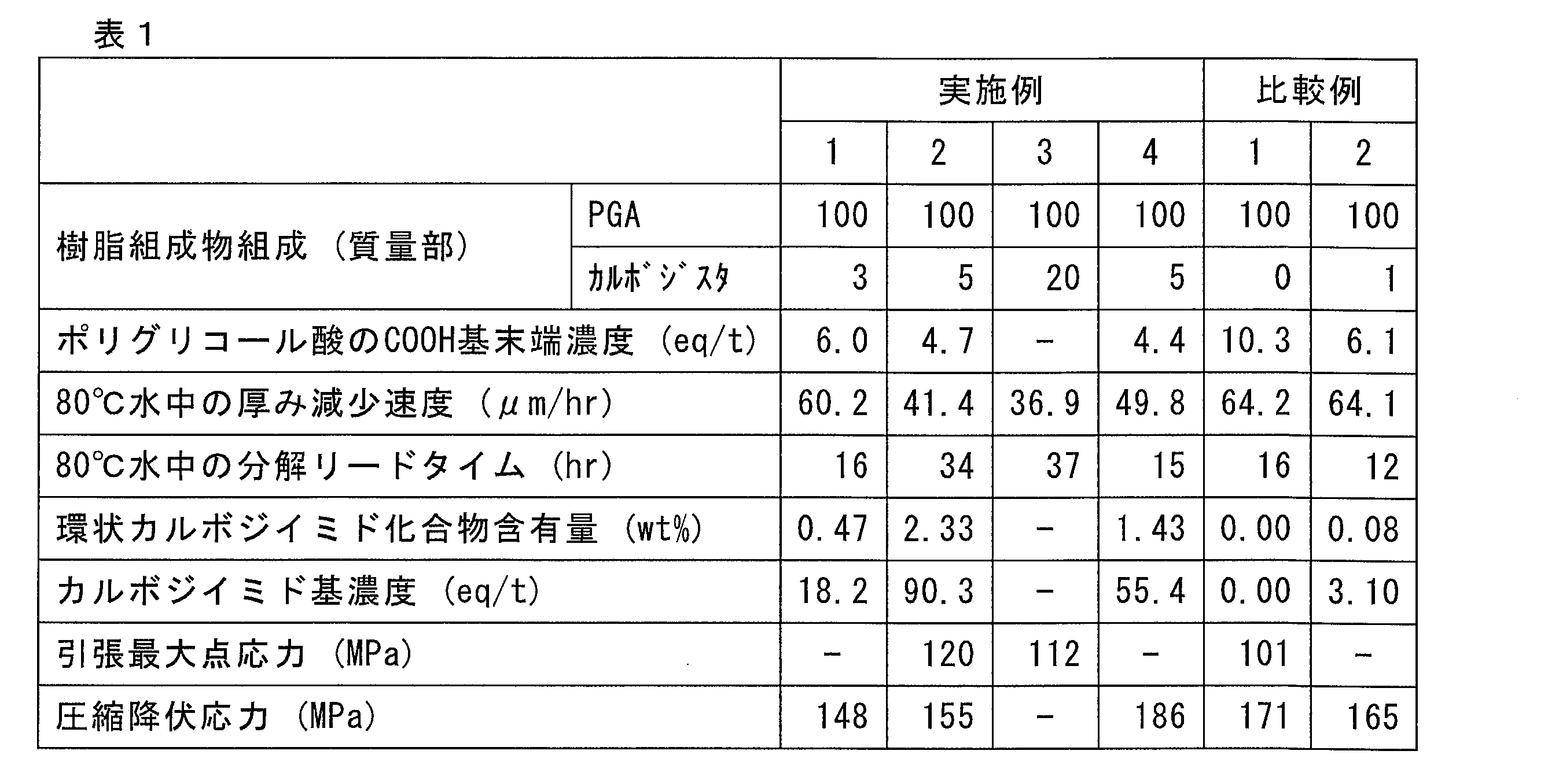
1、2、3 ダウンホールツール
5 ダウンホールプラグ
11、21、31 プラグ
14、24、34 筒状本体
16 第1の開口部
17 第2の開口部
18、28、38 第3の開口部
20 坑井壁
22 本体部
23 環状成形体
51 マンドレル
52 センターエレメント
53 ボール
54 ソケット
55、55a、55b コーン
56、56a、56b スリップ
57、57a、57b イコライザーリング
58 ロードリング
59 ボトム
121 第1の面
122 第2の面
5 ダウンホールプラグ
11、21、31 プラグ
14、24、34 筒状本体
16 第1の開口部
17 第2の開口部
18、28、38 第3の開口部
20 坑井壁
22 本体部
23 環状成形体
51 マンドレル
52 センターエレメント
53 ボール
54 ソケット
55、55a、55b コーン
56、56a、56b スリップ
57、57a、57b イコライザーリング
58 ロードリング
59 ボトム
121 第1の面
122 第2の面
Claims (15)
- ポリグリコール酸と環状カルボジイミド化合物とを含み、カルボジイミド基の濃度が15eq/t以上であるポリグリコール酸樹脂組成物から形成された樹脂成形体を備える、または該樹脂成形体によって構成される、坑井内の流体の流通を一時的に妨げるためのプラグ。
- 上記環状カルボジイミド化合物の含有量が0.4質量%以上である、請求項1に記載のプラグ。
- 上記ポリグリコール酸のカルボキシル基末端の濃度が10eq/t以下である、請求項2に記載のプラグ。
- 上記樹脂成形体の引張強度が80MPa以上である、請求項2または3に記載のプラグ。
- 上記樹脂成形体の圧縮降伏応力が100MPa以上である、請求項2~4の何れか1項に記載のプラグ。
- 上記樹脂成形体は、80℃の水に48時間浸漬した後に、重量平均分子量が7万以上である中心部と重量平均分子量が2万以下の表層部とを含み、上記中心部の厚みと浸漬前の上記樹脂成形体の厚みとの差が0.1mm以上2.0mm以下となる樹脂成形体である、請求項2~5の何れか1項に記載のプラグ。
- ボール、ダート、ディスク、ネジまたはパッカーである、請求項2~6の何れか1項に記載のプラグ。
- 筒状部材の周面に設けた該筒状部材の内外を連通させる開口部を塞いで使用する上記プラグであり、
上記樹脂成形体は、上記プラグの使用時に上記筒状部材の外側に露出する第1の面と、使用時に上記筒状部材の内側に露出する第2の面とを有しており、
上記第1の面と上記第2の面との最短距離が6mm以上65mm以下である、請求項2~7の何れか1項に記載のプラグ。 - 上記樹脂成形体は、非分解性材料からなる別の成形体によって少なくとも一部が覆われている、請求項2~8の何れか1項に記載のプラグ。
- 上記別の成形体は外周面にネジ山を有する環状成形体であり、上記樹脂成形体は、上記環状成形体の環の内側に配置されている、請求項9に記載のプラグ。
- フラックプラグまたはブリッジプラグである、請求項2~6の何れか1項に記載のプラグ。
- 筒状本体と、請求項2~11の何れか1項に記載のプラグとを備え、
上記筒状本体は、その周面にその内外を連通させる開口部を有し、
上記プラグが、上記開口部を塞ぐように上記筒状本体に係合されている、ダウンホールツール。 - 請求項2~11の何れか1項に記載のプラグを用いて、坑井およびダウンホールツールの少なくとも一方の一つ以上の領域を一時的に目止めすること、および
上記プラグの上記樹脂成形体を分解させることで目止めを解消し、上記領域における流体の流路を変更することを含む、坑井処理方法。 - 請求項2~11の何れか1項に記載のプラグを坑井に設置して、前記坑井内の流体の流れを妨げること、および
上記樹脂成形体を分解させて上記流体の流れを回復することを含む、坑井処理方法。 - 始端に第1の開口部、および終端に第2の開口部を有し、該始端と該終端との間に第3の開口部をさらに有し、該第3の開口部が請求項2~10の何れか1項に記載のプラグによって目止めされたダウンホールツールを坑井に導入すること、
上記第1の開口部を通じて地上から上記ダウンホールツールに流体を圧入して、上記第2の開口部から上記坑井内に該流体を噴射させて上記坑井を洗浄すること、および
洗浄後、上記プラグの上記樹脂成形体を分解させて、上記第3の開口部を介した上記ダウンホールツール内外の流体の流通を可能とすることを含む、坑井処理方法。
Priority Applications (4)
| Application Number | Priority Date | Filing Date | Title |
|---|---|---|---|
| CN202180061677.4A CN116057119B (zh) | 2020-10-09 | 2021-10-11 | 堵塞器、井下工具以及坑井处理方法 |
| CA3195157A CA3195157A1 (en) | 2020-10-09 | 2021-10-11 | Plug, downhole tool, and well treatment method |
| EP21877783.7A EP4227355A4 (en) | 2020-10-09 | 2021-10-11 | Plug, downhole tool, and well treating method |
| US18/247,816 US12044094B2 (en) | 2020-10-09 | 2021-10-11 | Plug, downhole tool, and well treatment method |
Applications Claiming Priority (2)
| Application Number | Priority Date | Filing Date | Title |
|---|---|---|---|
| JP2020171457 | 2020-10-09 | ||
| JP2020-171457 | 2020-10-09 |
Publications (1)
| Publication Number | Publication Date |
|---|---|
| WO2022075484A1 true WO2022075484A1 (ja) | 2022-04-14 |
Family
ID=81126543
Family Applications (1)
| Application Number | Title | Priority Date | Filing Date |
|---|---|---|---|
| PCT/JP2021/037498 Ceased WO2022075484A1 (ja) | 2020-10-09 | 2021-10-11 | プラグ、ダウンホールツールおよび坑井処理方法 |
Country Status (5)
| Country | Link |
|---|---|
| US (1) | US12044094B2 (ja) |
| EP (1) | EP4227355A4 (ja) |
| CN (1) | CN116057119B (ja) |
| CA (1) | CA3195157A1 (ja) |
| WO (1) | WO2022075484A1 (ja) |
Families Citing this family (1)
| Publication number | Priority date | Publication date | Assignee | Title |
|---|---|---|---|---|
| US12631108B2 (en) | 2025-04-18 | 2026-05-19 | Zhejiang Tensing Science and Technology Co., Ltd. | Data logger and data acquisition hydraulic fracturing process |
Citations (7)
| Publication number | Priority date | Publication date | Assignee | Title |
|---|---|---|---|---|
| WO2011152199A1 (ja) * | 2010-06-04 | 2011-12-08 | 株式会社クレハ | 耐水性を改善したポリグリコール酸含有樹脂組成物 |
| WO2013183363A1 (ja) | 2012-06-07 | 2013-12-12 | 株式会社クレハ | 炭化水素資源回収ダウンホールツール用部材 |
| WO2015072317A1 (ja) * | 2013-11-15 | 2015-05-21 | 株式会社クレハ | 坑井掘削用一時目止め剤 |
| JP2015160872A (ja) | 2014-02-26 | 2015-09-07 | 帝人株式会社 | 樹脂組成物 |
| WO2015199647A1 (en) | 2014-06-23 | 2015-12-30 | Halliburton Energy Services, Inc. | A tool cemented in a wellbore containing a port plug dissolved by galvanic corrosion |
| JP2017200985A (ja) * | 2016-05-06 | 2017-11-09 | 株式会社クレハ | ポリグリコール酸樹脂組成物、坑井掘削用成形品及び坑井掘削方法 |
| US20170342306A1 (en) | 2014-11-14 | 2017-11-30 | Schlumberger Technology Corporation | Well treatment |
Family Cites Families (17)
| Publication number | Priority date | Publication date | Assignee | Title |
|---|---|---|---|---|
| WO2008010355A1 (en) * | 2006-07-21 | 2008-01-24 | Nec Corporation | Aliphatic polyester resin composition and process for producing the same |
| JP5178015B2 (ja) * | 2007-01-22 | 2013-04-10 | 株式会社クレハ | 芳香族ポリエステル系樹脂組成物およびその製造方法 |
| JP5612815B2 (ja) * | 2008-09-30 | 2014-10-22 | 株式会社クレハ | ポリグリコール酸系樹脂組成物及びその成形体、並びにポリグリコール酸系樹脂組成物の製造方法 |
| WO2010071212A1 (ja) * | 2008-12-15 | 2010-06-24 | 帝人株式会社 | 環状カルボジイミドを使用する方法 |
| CN102245703B (zh) * | 2008-12-15 | 2015-04-29 | 帝人株式会社 | 含有环状碳二亚胺的树脂组合物 |
| US9181772B2 (en) | 2009-04-21 | 2015-11-10 | W. Lynn Frazier | Decomposable impediments for downhole plugs |
| US9127527B2 (en) * | 2009-04-21 | 2015-09-08 | W. Lynn Frazier | Decomposable impediments for downhole tools and methods for using same |
| JP2012149208A (ja) * | 2011-01-21 | 2012-08-09 | Kureha Corp | ポリグリコール酸の分解方法 |
| US20140377555A1 (en) * | 2012-03-01 | 2014-12-25 | Kureha Corporation | Water-disintegrable composite fiber and method of producing the same |
| JP6133847B2 (ja) | 2012-04-27 | 2017-05-24 | 株式会社クレハ | ポリエステル樹脂組成物およびその成形体 |
| US20150105521A1 (en) * | 2012-06-29 | 2015-04-16 | Teijin Limited | Resin composition |
| EP2980157A4 (en) * | 2013-03-25 | 2016-11-30 | Teijin Ltd | Resin composition |
| US20160145483A1 (en) * | 2014-11-26 | 2016-05-26 | Schlumberger Technology Corporation | Well treatment |
| US11136461B2 (en) | 2014-12-22 | 2021-10-05 | Schlumberger Technology Corporation | Degradable composite structures |
| JP6513452B2 (ja) * | 2015-03-30 | 2019-05-15 | 株式会社クレハ | ポリグリコール酸成形物、ダウンホールツール用部材、及び、ポリグリコール酸成形物の製造方法 |
| JP2019060219A (ja) * | 2017-09-22 | 2019-04-18 | 株式会社クレハ | ダウンホールツール部材及びその製造方法 |
| CN211038596U (zh) * | 2019-12-18 | 2020-07-17 | 新疆恒智伟业石油工程技术开发有限公司 | 一种高强度可溶暂堵打孔筛管 |
-
2021
- 2021-10-11 EP EP21877783.7A patent/EP4227355A4/en active Pending
- 2021-10-11 WO PCT/JP2021/037498 patent/WO2022075484A1/ja not_active Ceased
- 2021-10-11 US US18/247,816 patent/US12044094B2/en active Active
- 2021-10-11 CA CA3195157A patent/CA3195157A1/en active Pending
- 2021-10-11 CN CN202180061677.4A patent/CN116057119B/zh active Active
Patent Citations (7)
| Publication number | Priority date | Publication date | Assignee | Title |
|---|---|---|---|---|
| WO2011152199A1 (ja) * | 2010-06-04 | 2011-12-08 | 株式会社クレハ | 耐水性を改善したポリグリコール酸含有樹脂組成物 |
| WO2013183363A1 (ja) | 2012-06-07 | 2013-12-12 | 株式会社クレハ | 炭化水素資源回収ダウンホールツール用部材 |
| WO2015072317A1 (ja) * | 2013-11-15 | 2015-05-21 | 株式会社クレハ | 坑井掘削用一時目止め剤 |
| JP2015160872A (ja) | 2014-02-26 | 2015-09-07 | 帝人株式会社 | 樹脂組成物 |
| WO2015199647A1 (en) | 2014-06-23 | 2015-12-30 | Halliburton Energy Services, Inc. | A tool cemented in a wellbore containing a port plug dissolved by galvanic corrosion |
| US20170342306A1 (en) | 2014-11-14 | 2017-11-30 | Schlumberger Technology Corporation | Well treatment |
| JP2017200985A (ja) * | 2016-05-06 | 2017-11-09 | 株式会社クレハ | ポリグリコール酸樹脂組成物、坑井掘削用成形品及び坑井掘削方法 |
Non-Patent Citations (1)
| Title |
|---|
| See also references of EP4227355A4 |
Also Published As
| Publication number | Publication date |
|---|---|
| EP4227355A4 (en) | 2024-03-13 |
| EP4227355A1 (en) | 2023-08-16 |
| US12044094B2 (en) | 2024-07-23 |
| CA3195157A1 (en) | 2022-04-14 |
| CN116057119B (zh) | 2026-02-17 |
| CN116057119A (zh) | 2023-05-02 |
| US20230374880A1 (en) | 2023-11-23 |
Similar Documents
| Publication | Publication Date | Title |
|---|---|---|
| US7036587B2 (en) | Methods of diverting treating fluids in subterranean zones and degradable diverting materials | |
| RU2470141C2 (ru) | Способ улучшения изоляции уплотняющими шариками | |
| CA2889132C (en) | Expanded wellbore servicing materials and methods of making and using same | |
| RU2690577C1 (ru) | Флюиды и способы для обработки нефтегазоносных пластов | |
| US9951266B2 (en) | Expanded wellbore servicing materials and methods of making and using same | |
| US8714249B1 (en) | Wellbore servicing materials and methods of making and using same | |
| CA2889141C (en) | Wellbore servicing fluids comprising foamed materials and methods of making and using same | |
| US20180155597A1 (en) | Controlled release system for the release of oil field chemicals and use of the system for reservoir treatment and monitoring | |
| US10724340B2 (en) | Chelating agents and scale inhibitors in degradable downhole tools | |
| US9376888B2 (en) | Diverting resin for stabilizing particulate in a well | |
| US20050059557A1 (en) | Subterranean treatment fluids and methods of treating subterranean formations | |
| FR3025244A1 (fr) | Operations de formation souterraine utilisant des dispositifs degradables d'isolation des puits de forage. | |
| WO2001094744A1 (en) | Microcapsule well treatment | |
| MX2011008782A (es) | Metodo para la desviacion de tratamientos de fractura hidraulica. | |
| SA516371284B1 (ar) | نظام وطريقة لمعالجة تكوين جوفي بتركيبة تحويل | |
| US9353307B2 (en) | Method of preparing polymer-water emulsion and further settling a sticky polymer material in downhole environment | |
| WO2017209768A1 (en) | Treatments in subterranean formations using degradable polymers in organic solvents | |
| JP2017115106A (ja) | 組成物、ダウンホールツール用組成物、ダウンホールツール用分解性ゴム部材、ダウンホールツール、及び坑井掘削方法 | |
| US7198103B2 (en) | Method for stimulating a petroleum well | |
| CN116057119B (zh) | 堵塞器、井下工具以及坑井处理方法 | |
| WO2023053955A1 (ja) | 樹脂組成物、ダウンホールツールまたはその部材、プラグおよび坑井処理方法 | |
| RU2363841C1 (ru) | Способ поинтервальной изоляции и ограничения водопритоков в горизонтальные скважины | |
| US20180134947A1 (en) | Methods for treating high temperature subterranean formations | |
| CN119531819A (zh) | 多簇层间/缝内暂堵转向压裂工艺及产品制备方法 | |
| US11407934B2 (en) | Degradable diversion material having a polyacrylate compound |
Legal Events
| Date | Code | Title | Description |
|---|---|---|---|
| 121 | Ep: the epo has been informed by wipo that ep was designated in this application |
Ref document number: 21877783 Country of ref document: EP Kind code of ref document: A1 |
|
| ENP | Entry into the national phase |
Ref document number: 3195157 Country of ref document: CA |
|
| NENP | Non-entry into the national phase |
Ref country code: DE |
|
| ENP | Entry into the national phase |
Ref document number: 2021877783 Country of ref document: EP Effective date: 20230509 |
|
| NENP | Non-entry into the national phase |
Ref country code: JP |