WO2022077403A1 - Procédé et dispositif de communication - Google Patents
Procédé et dispositif de communication Download PDFInfo
- Publication number
- WO2022077403A1 WO2022077403A1 PCT/CN2020/121328 CN2020121328W WO2022077403A1 WO 2022077403 A1 WO2022077403 A1 WO 2022077403A1 CN 2020121328 W CN2020121328 W CN 2020121328W WO 2022077403 A1 WO2022077403 A1 WO 2022077403A1
- Authority
- WO
- WIPO (PCT)
- Prior art keywords
- time
- time unit
- dmrs
- information
- domain position
- Prior art date
- Legal status (The legal status is an assumption and is not a legal conclusion. Google has not performed a legal analysis and makes no representation as to the accuracy of the status listed.)
- Ceased
Links
Images






Classifications
-
- H—ELECTRICITY
- H04—ELECTRIC COMMUNICATION TECHNIQUE
- H04W—WIRELESS COMMUNICATION NETWORKS
- H04W72/00—Local resource management
- H04W72/04—Wireless resource allocation
Definitions
- the present application relates to the field of wireless communication technologies, and in particular, to a communication method and apparatus.
- the uplink transmission of the low priority is cancelled, and the uplink transmission of the low priority is not resumed.
- uplink transmission is also interrupted.
- the uplink transmission is canceled by UL CI or higher priority transmission, the canceled uplink transmission will not resume transmission, and the flexibility of the transmission mode is insufficient and needs to be improved.
- the present application provides a communication method to improve the flexibility of the transmission mode in the scenario where the uplink transmission is canceled.
- an embodiment of the present application provides a communication method, and the method can be executed by a terminal device or a component in the terminal device (such as a processor, a communication chip, or a chip system, etc.).
- the terminal device receives first information, where the first information is used to indicate cancellation of uplink transmission at the first time domain location, where the uplink transmission includes DMRS and/or data transmission; the first time domain location is the same as the The first time unit has an overlap, and the time domain position of the first DMRS in the first time unit is determined according to the first pattern.
- the first information is further used to indicate one of the following: cancel the first DMRS transmission after the first time domain position in the first time unit; or cancel the first DMRS transmission in the first time unit.
- the first DMRS is transmitted after the first time domain position, and the first DMRS is transmitted according to the first pattern in the second time unit after the first time domain position, and the length of the second time unit is the same as that of the first time unit.
- the second DMRS is transmitted according to the second pattern in a third time unit after the first time domain position, and the first time unit includes the third time unit.
- the terminal device may cancel the DMRS transmission after the first time domain position on the first time unit according to the first information; or cancel the DMRS transmission after the first time domain position on the first time unit, and send the first DMRS according to the first information in the second time unit according to the first pattern; or send the first DMRS according to the second pattern in the third time unit according to the first information the second DMRS.
- the terminal device can cancel the DMRS transmission after the first time domain position in the first time unit when the uplink transmission at the first time domain position is canceled according to the indication of the first information; DMRS transmission after the first time domain position on the first time unit, and sending the first DMRS in the second time unit according to the first pattern according to the first information; or, according to the first A message is sent according to the second pattern in the third time unit, thereby improving the flexibility of the processing method when the uplink transmission at the first time domain position is canceled.
- nK+1 fourth time units M, n, K, and N are positive integers, and n is less than or equal to N; or, (pattern4) the first time
- the unit includes N fifth time units, each fifth time unit includes K consecutive fourth time units, and the first pattern indicates that the first DMRS occupies the first fourth time in each fifth time unit unit, K is a positive integer.
- the first pattern can be designed in various ways to improve scheduling flexibility.
- the design of DMRS distributed in part of the fourth time unit in the first time unit can save DMRS overhead and improve spectrum efficiency.
- the terminal device when the transmission of the first DMRS in the first pattern is canceled, the terminal device can be made to restore the DMRS in the second time unit or the third time unit after the first time domain position. , so that the base station side performs channel estimation and decoding according to the restored DMRS, so that the uplink transmission can be resumed.
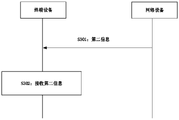
- the terminal device may also receive second information, where the second information may include indication information of the first pattern, the value of K, the value of N, the value of M, or the value of the first time unit. at least one of the indication information of the RV of the first time slot.
- the first time unit includes multiple time slots
- the terminal device may determine the first time slot after the first time domain position according to the RV of the last time slot before the first time domain position RV.
- the terminal device may receive third information, where the third information is used to indicate that the first time-domain position after the first time-domain position is determined according to the RV of the last time-slot before the first time-domain position RV of a slot.
- the control of the RV determination method can be realized by the network device.
- the terminal device may receive fourth information, where the fourth information is used to indicate the time domain positions of multiple consecutive first time units, and each first time unit includes multiple fourth time units ; the RV of the fourth time unit of each of the plurality of consecutive first time units is independently determined.
- the RV continuity of the transmission actually received by the network device can be ensured, enabling incremental redundancy HARQ.
- the terminal device may receive fifth information, where the fifth information is used to indicate that the RV of the fourth time unit of each of the multiple consecutive first time units is independent of the RV Sure.
- the control of the RV determination method can be realized by the network device.
- the first information may be carried in a DCI or an RRC message, where the DCI is terminal equipment-specific control information or cell-specific control information or group-common control information.
- an embodiment of the present application provides a communication method, and the method can be executed by a network device or a component in the network device (such as a processor, a communication chip, or a chip system, etc.).
- the network equipment is eg a base station.
- the network device can send the first information, and the first information can refer to the description in the first aspect.
- the network device may also cancel the reception of the DMRS after the first time domain position on the first time unit according to the first information; or, receive the DMRS sent according to the first pattern in the second time unit according to the first information.
- the first DMRS or the first information receives the second DMRS sent according to the second pattern in the third time unit.
- the first pattern and/or the second pattern may refer to the description of the first aspect.
- the network device may send at least one of the second information, the third information, the fourth information, or the fifth information.
- the network device may send at least one of the second information, the third information, the fourth information, or the fifth information.
- second information, third information, fourth information and fifth information reference may be made to the description in the first aspect.
- the terminal device can receive first information, where the first information is used to indicate cancellation of uplink transmission at the first time domain position, where the uplink transmission includes DMRS and/or data transmission; the first time domain The location overlaps with the first time unit, and the time domain location of the first DMRS in the first time unit is determined according to the first pattern.
- the second time unit after a time domain position sends the first DMRS according to the first pattern, and the length of the second time unit is the same as that of the first time unit; or, cancel the first DMRS at the first time domain position and transmit the second DMRS according to the second pattern in a third time unit after the first time domain position, the first time unit includes the third time unit; or, in the first time domain
- the location transmits the first DMRS according to the first pattern.
- the sixth information includes at least one of the following: the first information; or, the time domain location information of the reference time domain location in the first time unit; the first time domain location and the first time The information of the time domain position of the unit coincidence; or, the indication information of the first pattern.
- the terminal device can, according to the sixth information, cancel the DMRS transmission after the first time domain position in the first time unit when the uplink transmission at the first time domain position is cancelled, or cancel the DMRS transmission at the first time domain position DMRS transmission after the first time domain position in the time unit, and sending the first DMRS in the second time unit according to the first pattern according to the first information, or according to the first information
- the second DMRS is sent according to the second pattern in the third time unit, thus improving the flexibility of the processing method when the uplink transmission at the first time domain position is canceled.
- the sixth information includes the overlapping time domain location information, and the overlapping time domain location includes the first fourth time unit in the first time unit, and the The first time unit includes at least one fourth time unit.
- the terminal device may perform according to the sixth information: cancel the transmission of the first DMRS at the first time domain position and cancel the transmission of the first DMRS after the first time domain position in the first time unit ; or, cancel the transmission of the first DMRS at the first time domain position and cancel the first DMRS transmission after the first time domain position in the first time unit, and cancel the first DMRS transmission at the first time domain position.
- a second time unit after a time domain position transmits the first DMRS according to the first pattern, and the length of the second time unit is the same as that of the first time unit.
- the sixth information includes indication information of the first pattern and the coincident time domain position information
- the first time unit includes K fourth time units
- the first pattern indicates
- the first DMRS occupies the central time unit in the K second time units
- K is a positive integer
- the overlapping time domain position includes the fourth time unit where at least one first DMRS in the first time unit is located.
- time unit and does not include the Kth fourth time unit of the first time unit.
- the terminal device performs according to the sixth information: canceling the transmission of the first DMRS at the first time domain position, and sending the second DMRS according to the second pattern at a third time unit after the first time domain position , the first time unit includes the third time unit.
- the sixth information includes indication information of the first pattern and the overlapping time domain position information, the first time unit includes K fourth time units, and the first time unit includes K fourth time units.
- the pattern indicates that the first DMRS occupies the first fourth time unit and the Kth fourth time unit in the K fourth time units, K is a positive integer, and the coincident time domain position does not include the Kth a fourth time unit; the terminal device may perform according to the sixth information: cancel the transmission of the first DMRS at the first time domain position, and the third time unit after the first time domain position according to the second
- the second DMRS is transmitted in a pattern, and the first time unit includes the third time unit.
- the sixth information includes indication information of the first pattern, the first information, the time-domain position information of the reference time-domain position, and the coincident time-domain position information;
- the first fourth time unit in the coincident time domain position is located after the fourth time unit where the reference time domain position is located, and the coincident time domain position does not include the first time unit indicated by the first pattern
- the fourth time unit where at least one first DMRS in the time unit is located, the first information is cell-specific or group-common control information; the terminal device executes according to the sixth information: at the first time domain position, follow the The first DMRS is transmitted in a first pattern.
- the sixth information includes indication information of the first pattern and the overlapping time domain position information; the first fourth time unit in the overlapping time domain position is located in the After the first fourth time unit of the first time unit, and the coincident time domain position includes the fourth time unit where at least one first DMRS in the first time unit indicated by the first pattern is located, so
- the first information is cell-specific or group-common control information; the terminal device performs according to the sixth information: sending the first DMRS according to the first pattern at the first time domain position.
- the network device may send at least one of the second information, the third information, the fourth information, or the fifth information.
- the network device may send at least one of the second information, the third information, the fourth information, or the fifth information.
- second information, third information, fourth information and fifth information reference may be made to the description in the first aspect.
- the network device may send first information, where the first information is used to instruct cancellation of uplink transmission at the first time domain location, where the uplink transmission includes DMRS and/or data transmission; the first time domain location There is an overlap with the first time unit, and the time domain position of the first DMRS in the first time unit is determined according to the first pattern.
- the network device performs according to the sixth information: cancelling the reception of the first DMRS at the first time domain position and cancelling the reception of the first DMRS after the first time domain position in the first time unit ; or, cancel the reception of the first DMRS at the first time domain position and cancel the reception of the first DMRS after the first time domain position in the first time unit, and cancel the reception of the first DMRS at the first time domain position.
- the second time unit after the first time domain position receives the first DMRS according to the first pattern, and the length of the second time unit is the same as that of the first time unit;
- the reception of the first DMRS, and the reception of the second DMRS according to the second pattern at a third time unit after the first time domain position, the first time unit includes the third time unit; the first time domain location receives the first DMRS according to the first pattern;
- the sixth information includes at least one of the following: the first information; or, time-domain location information of a reference time-domain location in a first time unit; the first time-domain location coincides with the first time unit information of the time domain position of ; the indication information of the first pattern.
- the sixth information includes indication information of the first pattern and the coincident time domain position information
- the first time unit includes K fourth time units
- the first pattern indicates The first DMRS occupies the central time unit in the K second time units, K is a positive integer
- the overlapping time domain position includes the fourth time unit where at least one first DMRS in the first time unit is located.
- time unit and does not include the Kth fourth time unit of the first time unit; the network device executes according to the sixth information: cancel the reception of the first DMRS at the first time domain position, and perform at the The third time unit after the first time domain position receives the second DMRS according to the second pattern.
- the sixth information includes indication information of the first pattern and the overlapping time domain position information, the first time unit includes K fourth time units, and the first time unit includes K fourth time units.
- the pattern indicates that the first DMRS occupies the first fourth time unit and the Kth fourth time unit in the K fourth time units, K is a positive integer, and the coincident time domain position does not include the Kth a fourth time unit; the network device performs according to the sixth information: cancels the reception of the first DMRS at the first time domain position, and the third time unit after the first time domain position according to the first time domain position
- the second DMRS is received in two patterns.
- the sixth information includes indication information of the first pattern and the coincident time domain position information
- the first time unit includes N consecutive fifth time units
- the coincident time domain position does not include the Mth fourth time unit; the network device performs according to the sixth information: cancel the reception of the first DMRS at the first time domain position, and cancel the reception of the first DMRS at the first time domain position.
- the third time unit after the time domain position receives the second DMRS according to the second pattern.
- the sixth information includes indication information of the first pattern and the overlapping time domain position information; the first fourth time unit in the overlapping time domain position is located in the After the first fourth time unit of the first time unit, and the coincident time domain position includes the fourth time unit where at least one first DMRS in the first time unit indicated by the first pattern is located, so
- the first information is cell-specific or group-common control information; the network device performs according to the sixth information: receiving the first DMRS according to the first pattern at the first time domain position.
- the first pattern and/or the second pattern may refer to the description of the first aspect.
- the network device may send at least one of the second information, the third information, the fourth information, or the fifth information.
- the network device may send at least one of the second information, the third information, the fourth information, or the fifth information.
- second information, third information, fourth information and fifth information reference may be made to the description in the first aspect.
- an embodiment of the present application provides a communication method, and the method can be executed by a terminal device or a component in the terminal device (such as a processor, a communication chip, or a chip system, etc.).
- the terminal device can receive the second information, where the second information includes at least one of the following items: indication information of the first pattern, where the first pattern is used to indicate the time domain in which the first DMRS in the first time unit is located position; or, the value of K is used to indicate the number of the fourth time unit in the first time unit, or, used to indicate the number of the fourth time unit in the fifth time unit; or, the value of N, Used to indicate the number of fifth time units in the first time unit; or, the value of M, when the first time unit includes N fifth time units, is used to indicate the fourth time unit in the first time unit , each of the fifth time units includes K fourth time units; or, the indication information of the RV of the first time slot in the first time unit.
- the second information includes at least one of the following items: indication information of the first pattern, where the first pattern is used to indicate the time domain in which the first DMRS in the first time unit is located position; or, the value of K is used to indicate the number of the fourth time unit in the first time unit,
- the indication of the first time unit can be achieved.
- the terminal device may receive fifth information, where the fifth information is used to indicate that the RV of the fourth time unit of each of the multiple consecutive first time units is independent of the RV Sure.
- an embodiment of the present application provides a communication method, and the method may be executed by a network device or a component in the network device (such as a processor, a communication chip, or a chip system, etc.).
- the network equipment is eg a base station.
- the network device can transmit the second information.
- the second information reference may be made to the description in the fifth aspect.
- the network device may also send fifth information, which may refer to the description in the fifth aspect.
- the network device may also send the fourth information and the fifth information.
- the fourth information reference may be made to the description in the first aspect.
- an embodiment of the present application provides a communication apparatus, which can implement the method implemented by a terminal device in the first aspect, the third aspect, the fifth aspect, or any possible designs thereof.
- the apparatus comprises corresponding units or components for carrying out the above-described method.
- the units included in the apparatus may be implemented by software and/or hardware.
- the apparatus may be, for example, a terminal device, or a component or a baseband chip, a system-on-chip, or a processor that can support the implementation of the above method in the terminal device.
- the communication device may include modular components such as a transceiver unit (or a communication module, a transceiver module) and a processing unit (or a processing module), and these modules may perform the first aspect, the third aspect, and the fifth aspect.
- the transceiver unit may be a transmitter and a receiver, or a transceiver obtained by integrating the transmitter and the receiver.
- the transceiver unit may include an antenna, a radio frequency circuit, and the like, and the processing unit may be a processor, such as a baseband chip.
- the transceiver unit may be a radio frequency unit, and the processing unit may be a processor.
- the transceiver unit may be an input/output interface of the chip system, and the processing unit may be a processor of the chip system, such as a central processing unit (central processing unit, CPU).
- the communication device may include modular components such as a transceiver unit (or a communication module, a transceiver module) and a processing unit (or a processing module), and these modules may perform the second aspect, the fourth aspect, and the sixth aspect.
- a transceiver unit may be a transmitter and a receiver, or a transceiver obtained by integrating the transmitter and the receiver.
- the transceiver unit may include an antenna, a radio frequency circuit, and the like, and the processing unit may be a processor, such as a baseband chip.
- the transceiver unit may be a radio frequency unit, and the processing unit may be a processor.
- the transceiver unit may be an input/output interface of the chip system, and the processing unit may be a processor of the chip system, such as a central processing unit (central processing unit, CPU).
- the transceiver unit can be used to perform the receiving and/or sending actions performed by the network device in the second aspect, the fourth aspect, the sixth aspect or any possible designs thereof, such as sending and/or sending the first information, the second information, etc. or DMRS reception.
- the processing unit may be configured to perform actions other than the reception and transmission performed by the network device in the second aspect, the fourth aspect, the sixth aspect or any possible designs thereof, such as determining to stop the reception of the DMRS according to the first information or the sixth information , or determine to receive the DMRS according to the first information or the sixth information.
- An eleventh aspect provides a computer program product comprising instructions, the computer program product is used to store computer instructions, and when the computer instructions are run on a computer, the computer is made to execute the above-mentioned first to sixth aspects or any of them.
- a twelfth aspect provides a circuit coupled to a memory, the circuit being used to perform the method shown in the above-mentioned first to sixth aspects or any one of possible implementations thereof.
- the circuitry may include chip circuitry.
- FIG. 1 is a schematic diagram of the architecture of a communication system provided by an embodiment of the present application.
- FIG. 2 is a schematic flowchart of a communication method provided by an embodiment of the present application.
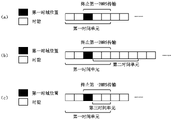
- FIG. 3 is a schematic diagram of a time domain position relationship between a first time unit and a first time domain position according to an embodiment of the present application
- FIG. 4 is a schematic diagram of a time domain position of a DMRS indicated by a first pattern according to an embodiment of the present application
- FIG. 5 is a schematic diagram of a time domain position of a DMRS indicated by a second pattern according to an embodiment of the present application
- FIG. 7 is a schematic flowchart of another communication method provided by an embodiment of the present application.
- FIG. 8 is a schematic structural diagram of a communication device according to an embodiment of the present application.
- FIG. 10 is a schematic structural diagram of another communication device provided by an embodiment of the present application.
- the present application provides a communication method.
- the present application will be described in further detail below with reference to the accompanying drawings. It should be understood that the specific operation methods in the method embodiments described below can also be applied to the apparatus embodiments or the system embodiments.
- the terminal device 101 may be configured to support communication with the network device through a universal user to network interface (universal user to network interface, Uu air interface).
- the terminal device 101 may have a wireless transceiver function, which can communicate with one or more network devices of one or more communication systems, and accept network services provided by the network devices, where the network devices include but are not limited to the network devices shown in the figure 102.
- the network device 102 may also be a chip with a communication module. It should be understood that in this application, the network device 102 may support Uu interface communication.
- the network device 102 can access a core network, such as a 5G core network, to obtain services on the core network side.
- the network device 102 includes but is not limited to: gNB, evolved node B (evolved node B, eNB) in LTE system, radio network controller (radio network controller, RNC), radio controller in CRAN system, base station control base station controller (BSC), home base station (for example, home evolved nodeB, or home node B, HNB), baseband unit (baseBand unit, BBU), transmitting and receiving point (transmitting and receiving point, TRP), transmitting point ( transmitting point, TP) or mobile switching center, etc.
- the network equipment 102 may also include base stations in future 6G or newer mobile communication systems.
- network devices may include centralized units (CUs) and distributed units (DUs).
- the network equipment may also include an active antenna unit (AAU).
- AAU active antenna unit
- CU implements some functions of network equipment, and DU implements some functions of network equipment.
- CU is responsible for processing non-real-time protocols and services, implementing radio resource control (RRC), packet data convergence layer protocol (packet data convergence protocol, PDCP) layer function.
- RRC radio resource control
- PDCP packet data convergence layer protocol
- the DU is responsible for processing physical layer protocols and real-time services, and implementing the functions of the radio link control (RLC) layer, the media access control (MAC) layer and the physical (PHY) layer.
- RLC radio link control
- MAC media access control
- PHY physical layer
- the uplink transmission of the terminal device can be realized.
- the following describes an uplink communication scenario between a terminal device and a network device as an example.
- the terminal device includes the terminal device 101 shown in FIG. 1
- the network device may include the network device 102 shown in FIG. 1 .
- the uplink transmission shown in this application includes sending an uplink channel sounding signal (sounding reference signal, SRS) from a terminal device to a network device, sending information carried on a physical uplink shared channel (physical uplink shared channel, PUSCH) (or referred to as sending a PUSCH bearer).
- SRS sounding reference signal
- PUSCH physical uplink shared channel
- PUSCH transmission or PUSCH transmission transmission of information carried on the physical uplink control channel (PUCCH) (or transmission of PUCCH bearer, referred to as PUCCH transmission or PUCCH transmission for short), or transmission carried in physical random access
- PUCCH physical uplink control channel
- PUCCH transmission or PUCCH transmission transmission carried in physical random access
- PRACH physical random access channel
- the network device may configure the terminal device to carry a demodulation reference signal (DMRS) in the uplink PUSCH, and perform channel estimation and decoding according to the DMRS sent by the terminal device.
- DMRS demodulation reference signal
- the DMRS may be located in part or all of orthogonal frequency division multiplexing (orthogonal frequency division multiplexing, OFDM) symbol positions in the time slot (slot) occupied by the PUSCH.
- the manner of canceling the uplink transmission will be described below. It should be understood that the cancelled uplink transmission may be a repetition transmission.
- the repeated transmission may be a transmission mode in which the same content is repeatedly transmitted multiple times according to the number of repeated transmissions configured by a radio resource control (radio resource control, RRC) message or DCI.
- RRC radio resource control
- UL CI is introduced in the physical layer enhancement to indicate the cancellation of uplink transmission.
- the UL CI can be indicated by the downlink control information (DCI) format (format) 2_4, and the physical resource block (PRB) and OFDM are notified to a group of terminal equipment.
- DCI downlink control information
- PRB physical resource block
- the uplink transmission is canceled on all OFDM symbols after the PRB indicated by the UL CI and the first OFDM symbol indicated by the UL CI.
- the uplink transmission is a repetition transmission
- the repeated transmission is cancelled on all OFDM symbols after the PRB indicated by the UL CI and the first OFDM symbol indicated by the UL CI, without affecting other repeated transmissions.
- the low-priority uplink transmission is cancelled by the high-priority transmission.
- uplink transmission 1 and uplink transmission 2 may be scheduled by the network device through downlink control information (downlink control information, DCI) or scheduled through RRC.
- DCI downlink control information
- the network device may indicate transmission resource 1 occupied by uplink transmission 1 through DCI, and indicate transmission resource 2 occupied by uplink transmission 2 through DCI.
- the upstream transmission may also be interrupted by the downstream transmission.
- an embodiment of the present application provides a communication method.
- the method may be implemented by a network device (or components in a network device (such as a processor, a chip or a system of chips, etc.)) and a terminal device (or a component in a terminal device (such as a processor, a chip or a system of chips, etc.)).
- the terminal device is, for example, the terminal device 101 shown in FIG. 1
- the network device is, for example, the network device 102 shown in FIG. 1 .
- the method may include the following steps:
- the network device sends first information, where the first information is used to instruct to cancel uplink transmission at the first time domain position, where the uplink transmission includes transmission of DMRS and/or data. Cancellation here can also be replaced by stop, termination or interruption, etc.
- the first time domain position may be a partial time domain position within a fourth time unit (such as a symbol, a combination of multiple symbols, a time slot, or a combination of multiple time slots), or a time domain position including at least one fourth time unit. Domain location.
- the terminal device receives the first information.
- the first time-domain location overlaps with the first time unit, the first time unit is an independently scheduled time-domain location, and the first time unit carries uplink transmission.
- the first time unit may include one or more fourth time units.
- the time domain position of the first DMRS in the first time unit is determined according to the first pattern, or in other words, the first pattern is used to indicate the position of the first DMRS in the first time unit. It can also be said that the first information is used to cancel sending the first DMRS according to the first pattern.
- the first time unit in this application may be independently scheduled.
- the independent scheduling means that the first time unit is used as the uplink resource indicated by the uplink scheduling information, or, the independent scheduling means that the first time unit is used as the smallest unit of the time domain resource of the uplink scheduling.
- each first time unit may be scheduled as an independent scheduling unit, or multiple first time units may be scheduled continuously.
- the first time unit may be referred to as a virtual super slot (VS-slot), and correspondingly, one time slot may be referred to as a normal slot (normal slot).
- VS-slot virtual super slot
- normal slot normal slot
- the above first information includes UL CI or scheduling information (such as DCI) for scheduling uplink transmission.
- the first information includes UL CI
- the first time domain position includes the time domain position indicated by the UL CI.
- the first information indicates an OFDM symbol
- the first time domain position includes the OFDM symbol indicated by the first information.
- the scheduling information is used to schedule an uplink transmission with a higher priority
- the first time domain position includes a time domain position occupied by the uplink transmission scheduled with the higher priority.
- the above first information may also be used to indicate to stop the transmission of the first DMRS located after the first time domain position in the first time unit, or in other words, the first information may indicate to stop the transmission of the first DMRS at the first time domain position transmitting and stopping the transmission of the first DMRS located after the first time domain position in the first time unit. In other words, the first information may be used to instruct to stop the transmission of the first DMRS at the first time domain position and stop the transmission of the first DMRS at the time domain position after the first time domain position within the first time unit.
- the terminal device can cancel the first time domain position and the first time domain position in the first time domain according to the first information.
- the length of the second time unit may be the same as that of the first time unit, or in other words, the time unit (such as a time slot and/or a symbol) in the second time unit
- the number of is the same as the number of time units in the first time unit.
- the length of the second time unit may not be the same as the first time unit, for example, the length of the second time unit is longer (or shorter than) the length of the first time unit.
- the first DMRS refers to the DMRS sent according to the first pattern
- the second DMRS refers to the DMRS sent according to the second pattern
- the first information may also indicate that the transmission of the first DMRS at the first time domain position is stopped.
- the third time unit may be a true subset of the first time unit, or in other words, the third time unit is a partial time domain position in the first time unit, or That is, all the time domain positions of the third time unit overlap with part of the time domain positions in the first time unit. In addition, part of the time domain position of the third time unit may not overlap with the first time unit.
- the third time unit includes a time domain position located after the first time domain position in the first time unit, and also includes the first time domain position. The time domain location outside the first time unit after the location.
- the first information includes one or more fields, wherein one or more fields may carry information used to indicate the first time domain location, information indicating canceling the uplink transmission at the first time domain location, indicating stopping.
- the first pattern can also be set in a way of distributing DMRS in each time slot in the existing way.
- the first information may be carried in an RRC message and/or DCI. Wherein, if the first information is carried in DCI, the first information may be scheduling information or UL CI.
- the DCI may be UE-specific control information, cell-specific control information, or group common control information.
- S102 The terminal device cancels the DMRS transmission in the first time unit according to the first information, or sends the first DMRS according to the first pattern in the second time unit according to the first information, or sends the first DMRS in the third time unit according to the first information
- the second DMRS is transmitted according to the second pattern.
- the network device can send the first information to the terminal device to instruct the terminal device to stop the first time unit after the first time domain position when canceling the first DMRS uplink transmission at the first time domain position.
- the transmission of the first DMRS in the The third time unit after the domain position sends the second DMRS according to the second pattern, or only stops sending the first DMRS at the first time domain position, so more flexible DMRS sending can be implemented in the scenario where uplink transmission needs to be canceled.
- the first patterns shown here are only exemplary, and should not be construed as showing all the first patterns.
- the position of the DMRS can be changed on the basis of any of the first patterns shown in FIG. 4 .
- the fourth time unit is a time slot as an example for description, that is to say, the time slot in the following example in FIG. 4 can be replaced with a fourth time unit. is replaced by a symbol, a combination of symbols, or a combination of slots.
- the DMRS is distributed over some or all of the symbols in each slot, as indicated by the number (a) in FIG. 4 .
- the first time unit may include K consecutive time slots, another first pattern provided by the present application may indicate that the first DMRS is located in the central time unit, and K is a positive integer.
- the DMRS may be distributed over some or all of the symbols of the central time unit.
- the first time unit can be continuously scheduled, for example, N first time units are continuously scheduled, and N is a positive integer greater than or equal to 2.
- the channel estimation result of the time slot in which the first DMRS is transmitted is multiplexed with the channel in the time slot in which the first DMRS is not transmitted in the first time unit.
- the first time unit may include K consecutive time slots, and another first pattern provided by the present application may indicate that the first DMRS is located at the first one in the first time unit
- the time slot and the Kth time slot (or, in other words, the last time slot), K is a positive integer.
- the DMRS may be distributed over some or all of the symbols in the first slot, and over some or all of the symbols in the Kth slot.
- the interpolation method is used to estimate the channel in the first time unit where the first DMRS is not sent according to the first time slot and the Kth time slot in the first time unit, or a joint channel estimation may be used.
- a channel is determined for each time slot within the first time unit.
- the DMRS may be distributed over some or all of the symbols in each of the 1st, K+1th, 2K+1th, . . . and nK+1th time slots in the first time unit.
- the channel of the time slot between the two first DMRSs in which the first DMRS is not sent is estimated by interpolation according to the two adjacent first DMRSs in the first time unit, or a joint channel may be used.
- the estimation determines the channel for each time slot within the first time unit.
- the first time unit may include K consecutive time slots, and another first pattern provided by the present application may indicate that the first DMRS is located at the first one in the first time unit time slot, K is a positive integer.
- the DMRS may be distributed over some or all of the symbols in the first slot.
- the channel estimation result of the time slot in which the first DMRS is transmitted is multiplexed with the channel in the time slot in which the first DMRS is not transmitted in the first time unit.
- DMRS-less that is, scheduling VS-slot, VS-slot includes multiple ordinary time slots, and at least one time slot No DMRS is sent on the VS-slot.
- the terminal device can be made to resume the transmission of the DMRS in the second time unit or the third time unit after the first time domain position, so that the base station can perform channel estimation and decoding according to the resumed DMRS. , so that the uplink transmission can be resumed.
- the above first pattern may be indicated by second information (for example, scheduling information), or in other words, the uplink transmission carried by the first time unit is scheduled by the second information.
- the second information may schedule a first time unit, or may be used to continuously schedule the same first time unit.
- the second information may be carried in an RRC message and/or DCI, or in other words, the first pattern may be indicated by an RRC message and/or DCI.
- the RRC message when an RRC message is used to indicate the first pattern, the RRC message can be used to schedule a plurality of consecutive (or called preconfigured grants (CG)) first time units, within the plurality of first time units
- CG preconfigured grants
- the first DMRS is the first pattern.
- the DCI can be used to schedule a single first time unit.
- the second information may include indication information of the first pattern, the value of K, the value of N, the value of M, or the first time slot in the first time unit (the time slot here is not replaced with a symbol, One or more of the indication information of the redundancy version (redundancy version, RV) of a combination of multiple symbols or a combination of multiple time slots).
- the indication information of the first pattern can be used to indicate the first pattern.
- the numbers (a) to (e) (or other first patterns not shown) shown in FIG. 4 correspond to one bit respectively.
- the first pattern may be indicated by a bitmap in the second information.
- the time slot position used to indicate the time slot where the first DMRS is located may be carried, where the time slot position may be a relative position in the first time unit, such as an index.
- the value of K and/or the value of N may be used to indicate the number of time slots included in the first time unit.
- the second information may indicate the value of K to indicate the number of time slots included in the first time unit, and the optional , the second information may indicate the value of N; for the number (d) shown in FIG. 4 , the second information may indicate the values of K and N to indicate the number of time slots included in the first time unit, or the second information may Indicate the value of M to indicate the number of time slots.
- the second information carried in the RRC message may indicate the values of K and N.
- the second information carried by each DCI may indicate the value of K.
- the second information may independently carry the value of K (or the indication information of the value of K) or the value of N (or the indication information of the value of N), or the value of ⁇ K,N ⁇
- the indication information of the value of K, the indication information of the value of N, and/or the meaning corresponding to the ⁇ K,N ⁇ tuple may be predefined or preconfigured.
- the RVs in the first time unit may be cyclically arranged in the order of 0, 2, 3, and 1.
- the second information indicates that the RV of the first time slot in the first time unit is 0, if the A time unit includes 5 time slots, and the RVs of the time slots in the first time unit are 0, 2, 3, 1, and 0, respectively.
- the terminal device may set the RV of the first time slot after the first time domain position according to the RV of the last time slot before the first time domain position.
- the third information may indicate that the RV of the first time slot after the first time domain position is determined according to the RV of the last time slot before the first time domain position.
- the third information may be carried in the same message as the second information.
- the third information may be sent separately, for example, the third information is sent through an RRC message, and the second information is sent through another RRC message or DCI.
- the terminal device receives fourth information, where the fourth information is used to schedule at least two first time units, or in other words, the fourth information is used to indicate the time domain positions of multiple consecutive first time units, if the second information If the RV of the first slot in the indicated first time unit is 0, the RVs of the slots in each first time unit are 0, 2, 3, 1, and 0 respectively.
- the fourth information is one type of the second information, that is, scheduling information carried by the RRC message.
- the fourth information may be the second information carried in the RRC message indicating that N is a positive integer greater than or equal to 2.
- the terminal device may independently determine the RV of the slot in each first time unit after receiving the fifth information.
- the fifth information may indicate that the RV of the second time unit of each of the plurality of consecutive first time units is independently determined.
- the fifth information may be carried in the same message as the second information.
- the fifth information may be sent separately, for example, the fifth information is sent through an RRC message, and the second information is sent through another RRC message or DCI.
- FIG. 5 is a schematic diagram of a second pattern provided by an embodiment of the present application. It should be understood that the second pattern shown here is only exemplary, and should not be construed as showing all possible second patterns. For example, on the basis of any second pattern shown in FIG. position to obtain other second patterns. It should be understood that in FIG. 5 , the fourth time unit is a time slot as an example for description, that is to say, the time slot in the following example in FIG. 5 can be replaced with a fourth time unit. is replaced by a symbol, a combination of symbols, or a combination of slots. Wherein, the fourth time unit in the second pattern may be the same as the fourth time unit in the first pattern.
- the second pattern may indicate that the second DMRS occupies every fourth time unit in the third time unit.
- the second DMRS may be located in part or all of the symbols in each slot.
- each slot includes the second DMRS.
- the third time unit may include K-(i+1) slots, and the second pattern is used to indicate that the second DMRS occupies the first slot, At least one of the center slot and the last slot. Wherein, the second DMRS occupies part or all of the symbols in the above time slots.
- the second pattern may indicate that the second DMRS is occupied as the central time unit in the third time unit.
- the second pattern may indicate that the second DMRS occupies the first slot and the last slot in the third time unit.
- the second pattern may indicate that the second DMRS occupies the first slot in the third time unit.
- the first information when the first information indicates that the transmission of the first DMRS at the first time domain position is stopped and the second DMRS is sent according to the second pattern in a third time unit after the first time domain position,
- the first information may also indicate a second pattern.
- the second pattern may be indicated by separate information, for example, the second pattern may be indicated by an RRC message or DCI.
- the second pattern can be associated with the first pattern, so the terminal device can determine the second pattern based on the first pattern without requiring the network device to indicate the second pattern. For example, if the first pattern indicates that the first DMRS occupies the central time unit of the first time unit (as shown by the number (b) in FIG. 4 ), the second pattern may indicate that the second DMRS occupies the central time unit of the third time unit (As shown in the number (b) of FIG. 5 ), the central time unit of the third time unit may be determined with reference to the central time unit of the first time unit. Similarly, if the first pattern indicates that the first DMRS occupies each slot in the first time unit (as shown in number (a) in FIG.
- the second pattern may indicate that the second DMRS occupies each of the third time units. slot (as shown in number (a) in Figure 5); if the first pattern indicates that the first DMRS occupies the first slot and the last slot in the first time unit (as shown in number (c) in Figure 4), then the first The two patterns can indicate that the second DMRS occupies the first slot and the last slot of the third time unit (as shown in the number (c) in FIG. 5 ); if the first pattern indicates that the first DMRS occupies the first slot in the first time unit slots (as shown in the number (e) in FIG. 4 ), or the first pattern indicates that the first DMRS occupies the 1st, K+1th, 2ndK+1th, . .
- the second pattern may indicate that the second DMRS occupies the first slot of the third time unit (as shown by number (d) in FIG. 5 ).
- the execution mode indicated by the first information above can be performed by the network device according to the first pattern, the first time domain position, the first time unit, the position of the reference time slot P set in the first time unit, or the first time At least one of the time domain position information of the coincidence of the unit and the first time domain position is determined, and the coincident position information can be used to indicate the coincidence time domain position of the first time unit and the first time domain position, and the coincident time domain position can be Determined according to the first time unit and the first time domain position.
- the first pattern, the first time domain position, the reference time slot P and the first time unit are configured by the network device. Therefore, for the network device, the first pattern, the first time domain position, the first time unit and the first time unit are configured by the network device.
- the time domain position where the time unit and the first time domain position coincide is known information.
- the fourth time unit is continued as a time slot as an example, that is, the time slot in the following examples may be replaced by the fourth time unit.
- the first information may indicate that the transmission of the first DMRS at the first time domain position is stopped and the transmission of the first DMRS at the first time unit after the first time domain position is stopped. transmission.
- the first condition includes: the first time domain position coincides with the first time slot in the first time unit.
- the first time domain position and the first time slot may overlap partially (that is, the overlapping time domain position is a partial symbol of the first time slot in the first time unit) or completely overlap (that is, That is, the coincident time domain positions include all symbols of the first slot in the first time unit).
- the first condition does not limit whether the first time domain position coincides with other time slots in the first time unit.
- the first time domain position may also be with a time slot other than the first time slot in the first time unit. or multiple time slots coincide.
- the first condition includes a second condition and a third condition.
- the first condition can be considered to be satisfied when either the second condition or the third condition is satisfied.
- the first condition may be considered not satisfied.
- the third condition includes: the first time domain position coincides with the first time slot in the first time unit, but the first time domain position does not coincide with all the time slots in the first time unit, or in other words, the first time domain position The location at least does not coincide with the last time slot in the first time unit.
- the first time domain position and the first time slot may overlap partially (that is, the overlapping time domain position is a partial symbol of the first time slot in the first time unit) or completely overlap (that is, That is, the coincident time domain positions include all symbols of the first slot in the first time unit).
- the first information may be used to indicate that the transmission of the first DMRS at the first time domain position is stopped and the transmission of the first DMRS at the first time domain position is stopped.
- the first DMRS is transmitted after the first time domain position in the time unit, and the first DMRS is transmitted according to the first pattern at the second time unit after the first time domain position.
- the first information may be used to stop the transmission of the first DMRS at the first time domain position, and the third time unit after the first time domain position according to the The second DMRS is transmitted in two patterns.
- the fourth condition includes: the first pattern is as shown in No. (b) of FIG. 4 (in other words, the first pattern indicates that the first DMRS is located in the central time unit of the first time unit), and the first time domain position and the first time The time domain position of the first DMRS in the unit coincides, but the first time domain position at least does not coincide with the last time slot in the first time unit (or in other words, the coincident time domain position does not include the last time slot) .
- the fifth condition includes: the first pattern is as shown in No. (c) of FIG. 4 (in other words, when the first time unit includes K time slots, the first pattern indicates that the first DMRS is located at the first time slot and the Kth time slot), and the first time domain position at least does not coincide with the last time slot of the first time unit.
- the following takes the first pattern shown in FIG. 4 as an example to illustrate the determination of the first information by the network device through an embodiment.
- the following examples are applicable to scenarios such as: the uplink transmission of the terminal device (the uplink transmission takes the time slot or the first time unit as the scheduling unit) is cancelled by the UL CI, or cancelled by other high-priority transmissions, or by the downlink transmission.
- Interrupt where other high-priority transmissions are normal-slot transmissions (that is, transmissions scheduled with time slots as the scheduling unit) or VS-slot transmissions (that is, transmissions scheduled with the first time unit as the scheduling unit, where the first time The unit is not necessarily the same as the first time unit corresponding to the canceled uplink transmission).
- the signaling for scheduling the high-priority transmission is higher layer signaling (eg, RRC message) or DCI.
- the higher layer signaling is cell-specific or UE-specific.
- the DCI is group common or UE-specific.
- the network device may use at least one of the first pattern, the first time domain position, the first time unit, or the position where the first time domain position coincides with the first time unit One determines the first information.
- the first information may be used to indicate that the transmission of the first DMRS at the first time domain position is stopped, and the second time unit after the first time domain position is in accordance with The first pattern transmits the first DMRS, wherein the length of the second time unit may be the same as the length of the first time unit; or, the first information may be used to indicate that transmission of the first DMRS at the first time domain position is stopped.
- the first time domain position and the first time unit all overlap, which means that the first time domain position and all the time slots in the first time unit may partially overlap (that is, the overlapping time domain position does not include at least the first time domain position one time slot in the time unit) or all overlapping (that is, the coincident time domain position includes all the time slots in the first time unit, but there is no specific limitation on whether it includes all the time slots, for example, except for the first time slot Except for the first symbol of a time slot, all the coincidences of all the time slots in the first time unit are included in the overlapping time domain position, which is all overlapping).
- the first time domain position partially overlaps with the first time unit, and the overlapping time domain position includes the first time slot of the first time unit but does not include the time slot in which the first DMRS is located in the first time unit, then the first The information may indicate to stop the transmission of the first DMRS at the first time domain position and to stop the transmission of the first DMRS located after the first time domain position in the first time unit; alternatively, the first information may be used to indicate to stop at the first time domain position. Transmission of the first DMRS at a time-domain location, and the first DMRS is transmitted in a first pattern at a second time unit after the first time-domain location. The length of the second time unit may be the same as the length of the first time unit; or, the first information may be used to indicate that the transmission of the first DMRS at the first time domain position is stopped.
- the first time domain position partially overlaps with the first time unit, which means that the first time domain position does not overlap with at least one time slot in the first time unit (that is, the overlapping time domain position does not include the first time at least one slot in the unit).
- the A piece of information may indicate to stop the transmission of the first DMRS at the first time domain position and stop the transmission of the first DMRS located after the first time domain position in the first time unit; alternatively, the first information may be used to indicate to stop at the The transmission of the first DMRS at the first time domain position, and the second time unit after the first time domain position transmits the first DMRS according to the first pattern, wherein the length of the second time unit may be the same as that of the first time unit.
- the lengths are the same; alternatively, the first information may be used to indicate that the transmission of the first DMRS at the first time domain position is stopped, and the second DMRS is sent according to the second pattern in the third time unit after the first time domain position,
- the third time unit may include a time slot located after the first time domain position in the first time unit, and the second pattern is shown as number (a) or number (b) in FIG. 5 .
- the first information may indicate to stop transmission of the first DMRS at the first time domain position.
- the first information may indicate that the transmission of the first DMRS at the first time domain position is stopped, and the second DMRS is sent according to the second pattern in the third time unit after the first time domain position , the third time unit may include a time slot located after the first time domain position in the first time unit, and the second pattern is shown as number (a) or number (b) in FIG. 5 .
- the first information may be Instructs to stop the transmission of the first DMRS at the first time domain position.
- the network device may set a reference time slot (or a reference time domain position), or may set a reference time slot in a predefined manner, according to the reference time slot, the first pattern
- the first information is determined by at least one of the first time domain location, the first time unit, or the location where the first time domain location coincides with the first time unit.
- the position in the first time unit determines the first information, where P is the index of the reference time slot in the first time unit, 0 ⁇ P ⁇ K, and K is the number of time slots included in the first time unit .
- the first information may be used to indicate that the transmission of the first DMRS at the first time domain position is stopped, and the second time unit after the first time domain position is in accordance with The first pattern transmits the first DMRS, wherein the length of the second time unit may be the same as the length of the first time unit; or, the first information may be used to indicate that transmission of the first DMRS at the first time domain position is stopped.
- the first information may indicate the first DMRS stopped at the first time-domain location and stop the transmission of the first DMRS located after the first time domain position in the first time unit; alternatively, the first information may be used to indicate to stop the transmission of the first DMRS at the first time domain position, and in the first time domain position
- the second time unit after a time domain position sends the first DMRS according to the first pattern, wherein the length of the second time unit may be the same as the length of the first time unit; or, the first information may be used to indicate stopping at the first time the transmission of the first DMRS at the first time domain position; alternatively, the first information may indicate that the transmission of the first DMRS at the first time domain position is stopped, and the third time unit after the first time domain position is sent according to the second pattern
- the third time unit may include a time slot located after the first time
- the first information may indicate that the transmission of the first DMRS at the first time domain position is stopped, and the third time unit after the first time domain position is sent according to the second pattern
- the third time unit may include a time slot located after the first time domain position in the first time unit, and the second pattern is shown as number (a) or number (c) in FIG. 5 .
- the overlapping time domain location may include reference time slot P or be located in reference time slot P
- the first information may indicate that the transmission of the first DMRS at the first time domain position is stopped, and the second DMRS is sent according to the second pattern at a third time unit after the first time domain position
- the third The time unit may include a time slot located after the first time domain position in the first time unit, and the second pattern is shown, for example, by number (a) or number (c) in FIG. 5 .
- the first information may be used to indicate stop in the first time domain position on the transmission of the first DMRS.
- the network device may set a reference time slot P for each fifth time unit in the first time unit, according to the reference time slot P, the first pattern, the first time slot
- the first information is determined by at least one of the domain location, the first time unit, or a location where the first time domain location coincides with the first time unit.
- the position in the first time unit determines the first information, wherein P is the index of the reference time slot in the fifth time unit, 0 ⁇ P ⁇ K, and K is the number of time slots included in the fifth time unit .
- the first information may be used to indicate that the transmission of the first DMRS at the first time domain position is stopped, and the second time unit after the first time domain position is in accordance with The first pattern transmits the first DMRS, wherein the length of the second time unit may be the same as the length of the first time unit; or, the first information may be used to indicate that transmission of the first DMRS at the first time domain position is stopped.
- the first information may indicate the first DMRS stopped at the first time-domain location and stop the transmission of the first DMRS located after the first time domain position in the first time unit; alternatively, the first information may be used to indicate to stop the transmission of the first DMRS at the first time domain position, and in the first time domain position
- the second time unit after a time domain position sends the first DMRS according to the first pattern, wherein the length of the second time unit may be the same as the length of the first time unit; or, the first information may be used to indicate stopping at the first time the transmission of the first DMRS at the first time domain position; alternatively, the first information may indicate that the transmission of the first DMRS at the first time domain position is stopped, and the third time unit after the first time domain position is sent according to the second pattern
- the second DMRS, the third time unit can include the time slot located after the first time domain position
- the first time slot occupied by the overlapping time domain position is located in the first time slot in a certain fifth time unit and the reference time slot of this fifth time unit between P (excluding the first time slot and the reference time slot), and the last time slot occupied by the coincident time domain position is located before the first first DMRS after the fifth time unit, then the first time slot
- the information may indicate that transmission of the first DMRS is stopped at the first time domain position, and that the second DMRS is transmitted according to the second pattern at a third time unit after the first time domain position, the third time unit may include overlapping The time slot located after the first time domain position in the fifth time unit where the last time slot occupied by the time domain position of , the second pattern is shown as number (a) or number (d) in FIG. 5 .
- the first time slot occupied by the overlapping time domain position is located in the reference time slot P in a certain fifth time unit or after the reference time slot P, and the overlapping The last time slot occupied by the time domain position is located before the first first DMRS after the fifth time unit, the first information may indicate that the transmission of the first DMRS at the first time domain position is stopped, and the first DMRS is stopped at the first time domain position.
- the third time unit after the time domain position transmits the second DMRS according to the second pattern
- the third time unit may include a fifth time unit where the last time slot occupied by the overlapping time domain position is located in the first time domain
- the second pattern is shown as number (a) or number (d) in FIG. 5, for example.
- the first information may indicate The transmission of the first DMRS at the first time domain position is stopped.
- the first information may be used to indicate stop in the first time domain position on the transmission of the first DMRS.
- an embodiment of the present application provides another communication method.
- the terminal device determines the action after receiving the information for canceling the uplink transmission of the first time domain location, and the network device does not need to indicate the action. .
- the method may include the following steps:
- the network device sends first information, where the first information is used to instruct to cancel uplink transmission at the first time domain position, where the uplink transmission includes transmission of DMRS and/or data. Cancellation here can also be replaced by stop, cancel, or interrupt, etc.
- the first time domain position may be a partial time domain position within a fourth time unit (such as a symbol, a combination of multiple symbols, a time slot, or a combination of multiple time slots), or a time domain position including at least one fourth time unit. Domain location.
- the terminal device receives the first information.
- the first time domain position overlaps with the first time unit.
- the first time unit is a time domain position occupied by the uplink transmission, and the first time unit may include one or more fourth time units.
- the time domain position of the first DMRS in the first time unit is determined according to the first pattern, or in other words, the first pattern is used to indicate the position of the first DMRS in the first time unit. It can also be said that the first information is used to cancel sending the first DMRS according to the first pattern.
- the first time unit in this application may be independently scheduled.
- the independent scheduling means that the first time unit is used as the uplink resource indicated by the uplink scheduling information.
- each first time unit may be scheduled as an independent scheduling unit, or multiple first time units may be scheduled continuously.
- the first time unit may be referred to as a virtual super slot (VS-slot), and correspondingly, one time slot may be referred to as a normal slot (normal slot).
- VS-slot virtual super slot
- normal slot normal slot
- the above first information includes UL CI or scheduling information (such as DCI) for scheduling uplink transmission.
- the first information includes UL CI
- the first time domain position is the time domain position indicated by the UL CI.
- the first information indicates an OFDM symbol
- the first time domain position includes the OFDM symbol indicated by the first information.
- the first information includes the UCL
- the DCI is used to schedule an uplink transmission with a higher priority
- the first time domain position includes a time domain position occupied by the uplink transmission scheduled with the higher priority.
- the terminal device can cancel the first time domain position and the first time domain position in the first time unit according to the sixth information.
- the network device may stop receiving the first DMRS at the first time domain position and stop receiving the first DMRS at the first time domain position after the first time domain position according to the sixth information. Stopping the reception of the DMRS can be understood that the network device does not need to monitor the DMRS.
- the unit transmits the first DMRS according to the first pattern.
- the length of the second time unit may be the same as that of the first time unit, or in other words, the number of time units (such as time slots and/or symbols) in the second time unit may be the same as that of the first time unit.
- the number of time units in a time unit is the same.
- the length of the second time unit may not be the same as the first time unit, for example, the length of the second time unit is longer (or shorter than) the length of the first time unit.
- the network device may stop receiving the first DMRS at the first time domain position and stop receiving the first DMRS at the first time domain position after the first time domain position according to the sixth information, and The first DMRS is received according to the first pattern at the second time unit.
- the first pattern may be configured by the network device to the terminal device, or the first pattern may be pre-configured, so the first pattern is known to the network device.
- the way of pre-configuration can be protocol definition, or pre-stored, etc.
- the transmission of the first DMRS at the first time domain position is stopped, and the second DMRS is transmitted according to the second pattern at a third time unit after the first time domain position.
- the third time unit may be a proper subset of the first time unit, or the third time unit is a partial time domain position in the first time unit, or the third time unit All the time domain positions of the time unit overlap with some of the time domain positions in the first time unit. In addition, part of the time domain position of the third time unit may not overlap with the first time unit.
- the third time unit includes a time domain position located after the first time domain position in the first time unit, and also includes the first time domain position.
- the network device may stop the transmission of the first DMRS at the first time domain position according to the sixth information, and receive the first DMRS according to the second pattern in the third time unit.
- the second pattern may be configured by the network device to the terminal device, or the second pattern may be pre-configured, so the second pattern is known to the network device.
- the first DMRS is sent according to the first pattern at the first time domain position (that is, the terminal device does not stop transmission of the first DMRS at the first time domain position).
- the network device may receive the first DMRS according to the first pattern at the first time domain position according to the sixth information.
- the network device may stop receiving the first DMRS at the first time domain position according to the sixth information.
- the above sixth information may include the first information, the time domain position information of the reference time domain position in the first time unit, the information of the time domain position where the first time unit and the first time domain position coincide, or the first pattern. at least one of the indication information.
- the reference time domain location is set by the network device, and can be indicated by the network device to the terminal device.
- the reference time domain position may be pre-configured, for example, the reference time domain position is located at a set position in the first time unit.
- the reference time domain position is, for example, a time slot or a combination of time slots.
- the first information may be carried in an RRC message and/or DCI.
- the first information may be scheduling information or UL CI.
- the DCI can be UE-specific control information or group common control information.
- the RRC message may be UE-specific or cell-specific control information.
- the sixth information may further include the first information.
- the sixth information may include information for determining that the DCI is UE-specific or group common information.
- the sixth information may include information for determining that the RRC message is UE-specific or cell-specific.
- the terminal device when canceling the uplink transmission of the first DMRS at the first time domain position, can simultaneously stop the transmission of the first DMRS located after the first time domain position in the first time unit according to the sixth information, or at the first time domain position.
- the second time unit after a time domain position sends the first DMRS according to the first pattern (ie, delays the transmission of the first DMRS in the first time unit), or the third time unit after the first time domain position according to the first
- the second DMRS is sent in two patterns, or the transmission of the first DMRS is only stopped at the first time domain position, or the transmission of the first DMRS is not stopped at the first time domain position, so it can be more flexible in the scenario where the uplink transmission needs to be canceled DMRS sent.
- first pattern is shown in any one of numbers (a), (b), (c), (d) or (e) in Figure 4, and the second pattern is numbered (a), (b) in Figure 5 , (c) or (d).
- the fourth time unit is continued as a time slot as an example, that is, the time slot in the following examples may be replaced by the fourth time unit.
- the terminal device may stop the transmission of the first DMRS at the first time domain position and stop the transmission of the first DMRS at the first time unit after the first time domain position.
- the first condition includes: the first time domain position coincides with the first time slot in the first time unit.
- the first time domain position and the first time slot may overlap partially (that is, the overlapping time domain position is a partial symbol of the first time slot in the first time unit) or completely overlap (that is, That is, the coincident time domain positions include all symbols of the first slot in the first time unit).
- the first condition does not limit whether the first time domain position coincides with other time slots in the first time unit.
- the first time domain position and the first time unit may be located in a time slot other than the first time slot. or multiple time slots coincide.
- the first condition includes a second condition and a third condition.
- the first condition may be considered to be satisfied when the second condition or the third condition is satisfied.
- the first condition may be considered not satisfied.
- the second condition includes: the first time domain position coincides with all time slots in the first time unit.
- the first time domain position and all the time slots in the first time unit may partially overlap (that is, the overlapping time domain position does not include at least one time slot in the first time unit) or completely overlap (that is, , the coincident time domain position includes all the time slots in the first time unit, but there is no specific limitation on whether it includes all the time slots. For example, except for the first symbol of the first time slot, the first time unit All coincidences of all time slots in are included in the coincident time domain positions, then all overlap).
- the third condition includes: the first time domain position coincides with the first time slot in the first time unit, but the first time domain position does not coincide with all the time slots in the first time unit, or in other words, the first time domain position The location at least does not coincide with the last time slot in the first time unit.
- the first time domain position and the first time slot may overlap partially (that is, the overlapping time domain position is a partial symbol of the first time slot in the first time unit) or completely overlap (that is, That is, the coincident time domain positions include all symbols of the first slot in the first time unit).
- the terminal device may also stop the transmission of the first DMRS at the first time domain position and stop at the first time unit
- the first DMRS is transmitted after the first time-domain position in the , and the first DMRS is transmitted according to the first pattern at the second time unit after the first time-domain position.
- the terminal device may stop the transmission of the first DMRS at the first time domain position, and the third time unit after the first time domain position according to the second pattern The second DMRS is sent.
- the fourth condition includes: the first pattern is as shown in No. (b) of FIG. 4 (in other words, the first pattern indicates that the first DMRS is located in the central time unit of the first time unit), and the first time domain position and the first time The time domain position of the first DMRS in the unit coincides, but the first time domain position at least does not coincide with the last time slot in the first time unit (or in other words, the coincident time domain position does not include the last time slot) .
- the fifth condition includes: the first pattern is as shown in No. (c) of FIG. 4 (in other words, when the first time unit includes K time slots, the first pattern indicates that the first DMRS is located at the first time slot and the Kth time slot), and the first time domain position at least does not coincide with the last time slot of the first time unit.
- the terminal device may send the first DMRS according to the first pattern at the first time domain position.
- the seventh condition includes: the first time slot in the coincident time domain position is located after the time slot where the reference time domain position is located, and the coincident time domain position does not include at least one first time slot in the first time unit indicated by the first pattern.
- the first information is cell-specific or group-common control information.
- the eighth condition includes that the first time slot in the coincident time domain position is located after the first time slot in the first time unit, and the coincident time domain position includes the first time unit in the first time unit indicated by the first pattern
- the time slot where at least one first DMRS is located, and the first information is cell-specific or group-common control information.
- the actions that the terminal device determines according to the sixth information and needs to be performed are described through embodiments.
- the following examples are applicable to scenarios such as: the uplink transmission of the terminal device (the uplink transmission takes the time slot or the first time unit as the scheduling unit) is cancelled by the UL CI, or cancelled by other high-priority transmissions, or by the downlink transmission.
- the signaling for scheduling the high-priority transmission is high-level signaling or DCI.
- the higher layer signaling is cell-specific or UE-specific.
- the DCI is group common or UE-specific (in other words, the first information is cell-specific or group common or UE-specific control information).
- the terminal device can be based on at least one of the first pattern, the first time domain position, the first time unit, or the position where the first time domain position coincides with the first time unit One determines the action that needs to be performed, and executes that action.
- the terminal device may perform one of the following: may stop transmission of the first DMRS at the first time domain position, and the first time domain position after the first time domain position Two time units send the first DMRS according to the first pattern, wherein the length of the second time unit may be the same as the length of the first time unit; transmission.
- the first time domain position and the first time unit all overlap, which means that the first time domain position and all the time slots in the first time unit may partially overlap (that is, the overlapping time domain position does not include at least the first time domain position one time slot in the time unit) or all overlapping (that is, the coincident time domain position includes all the time slots in the first time unit, but there is no specific limitation on whether it includes all the time slots, for example, except for the first time slot Except for the first symbol of a time slot, all the coincidences of all the time slots in the first time unit are included in the overlapping time domain position, which is all overlapping).
- the terminal equipment performing one of the following: stopping the transmission of the first DMRS at the first time-domain position and stopping the transmission of the first DMRS at the first time-domain position after the first time-domain position; or, stopping at the first time
- the transmission of the first DMRS on the domain position, and the second time unit after the first time domain position sends the first DMRS according to the first pattern, wherein the length of the second time unit may be the same as the length of the first time unit;
- the terminal device may stop transmission of the first DMRS at the first time domain location.
- the first time domain position partially overlaps with the first time unit, which means that the first time domain position does not overlap with at least one time slot in the first time unit (that is, the overlapping time domain position does not include the first time at least one slot in the unit).
- the terminal The device performs one of the following: stopping the transmission of the first DMRS at the first time-domain position and stopping the transmission of the first DMRS at the first time-domain position after the first time-domain position; or, stopping at the first The transmission of the first DMRS at the time domain position, and the second time unit after the first time domain position transmits the first DMRS according to the first pattern, wherein the length of the second time unit may be the same as the length of the first time unit Or, stop the transmission of the first DMRS at the first time domain position, and send the second DMRS according to the second pattern at a third time unit after the first time domain position, and the third time unit may include the For a time slot located after the first time domain position in a time unit, the second pattern is shown as number (a) or number (b)
- the terminal device may stop transmission of the first DMRS at the first time domain location.
- the terminal device can stop the transmission of the first DMRS at the first time domain position, and send the second DMRS according to the second pattern in the third time unit after the first time domain position, the
- the third time unit may include a time slot located after the first time domain position in the first time unit, and the second pattern is shown by, for example, number (a) or number (b) in FIG. 5 .
- the terminal device may stop if the first time domain location partially overlaps the first time unit, and the overlapping time domain location does not include the first time slot of the first time unit and includes the last time slot in the first time unit Transmission of the first DMRS at the first time domain location.
- the network device may set the reference time slot P, or may determine the reference time slot in a pre-configured manner, and the terminal device may set the reference time slot P according to the reference time slot P, the first pattern, the first At least one piece of information in the time domain position, the first time unit, or the position where the first time domain position coincides with the first time unit determines an action to be performed, and executes the action.
- the position in the first time unit determines the first information, where P is the index of the reference time slot in the first time unit, 0 ⁇ P ⁇ K, and K is the number of time slots included in the first time unit .
- the terminal device may stop transmission of the first DMRS at the first time domain position, and the second time unit after the first time domain position follows the first pattern
- the first DMRS is sent, wherein the length of the second time unit may be the same as the length of the first time unit; or, the terminal device may stop transmission of the first DMRS at the first time domain position.
- the terminal device may stop transmission of the first DMRS at the first time domain location and stop the transmission of the first DMRS located after the first time domain position in the first time unit; alternatively, the terminal device may stop the transmission of the first DMRS at the first time domain position, and after the first time domain position
- the second time unit of the first time unit sends the first DMRS according to the first pattern, wherein the length of the second time unit may be the same as the length of the first time unit; transmission; alternatively, the terminal device may stop transmission of the first DMRS at the first time domain position, and transmit the second DMRS according to the second pattern at a third time unit after the first time domain position, the third time
- the unit may include time slots located after the first time domain position in the first time unit, and the second pattern is shown, for example, by number (a) or number (c) in FIG. 5 .
- the terminal device may stop the transmission of the first DMRS at the first time domain position, and send the For the second DMRS, the third time unit may include a time slot located after the first time domain position in the first time unit, and the second pattern is shown as number (a) or number (c) in FIG. 5 .
- the overlapping time domain location may include reference time slot P or be located in reference time slot P
- the terminal device may stop the transmission of the first DMRS at the first time domain position, and send the second DMRS according to the second pattern at a third time unit after the first time domain position, the third time unit
- the time slot located after the first time domain position in the first time unit may be included, and the second pattern is shown as number (a) or number (c) in FIG. 5 for example.
- the terminal device may also send the first DMRS at the first time domain position according to the first pattern.
- the terminal device may also send the first DMRS according to the first pattern at the first time domain position.
- the terminal device may stop the operation at the first time domain position Transmission of the first DMRS.
- the network device may set a reference time slot P for each fifth time unit in the first time unit (or determine the reference time slot in a preconfigured manner), and the terminal device may set a reference time slot P for each fifth time unit in the first time unit.
- the action to be performed may be determined according to at least one information of the reference time slot P, the first pattern, the first time domain position, the first time unit, or the position where the first time domain position coincides with the first time unit, and execute the action .
- the position in the first time unit determines the first information, wherein P is the index of the reference time slot in the fifth time unit, 0 ⁇ P ⁇ K, and K is the number of time slots included in the fifth time unit .
- the terminal device may stop transmission of the first DMRS at the first time domain position, and the second time unit after the first time domain position follows the first pattern
- the first DMRS is sent, wherein the length of the second time unit may be the same as the length of the first time unit; or, the first information may be used to indicate that the transmission of the first DMRS at the first time domain position is stopped.
- the terminal device may stop transmission of the first DMRS at the first time domain location and stop the transmission of the first DMRS located after the first time domain position in the first time unit; alternatively, the terminal device may stop the transmission of the first DMRS at the first time domain position, and after the first time domain position
- the second time unit of the second time unit sends the first DMRS according to the first pattern, wherein the length of the second time unit may be the same as the length of the first time unit; Transmission of a DMRS; alternatively, the terminal device may stop transmission of the first DMRS at the first time domain position, and transmit the second DMRS in a second pattern at a third time unit after the first time domain position
- the The third time unit may include a time slot located after the first time domain position in the fifth time unit where the last slot occupied by the first time domain position is located, and the second pattern is, for example, number (a) or number
- the terminal equipment The transmission of the first DMRS at the first time domain position may be stopped, and the second DMRS may be transmitted according to the second pattern at a third time unit after the first time domain position, the third time unit may include overlapping time The time slot in the fifth time unit where the last time slot occupied by the domain position is located after the first time domain position, and the second pattern is shown as number (a) or number (d) in FIG. 5 for example.
- the terminal device can stop the transmission of the first DMRS at the first time domain position, and in the first time domain
- the third time unit after the location sends the second DMRS according to the second pattern, and the third time unit may include that the last time slot occupied by the overlapping time domain locations is located after the first time domain location in the fifth time unit where the last time slot is located , the second pattern is shown as number (a) or number (d) in FIG. 5 .
- the terminal device may also send the first DMRS at the first time domain position according to the first pattern.
- the terminal device may stop the transmission of the first DMRS at the first time domain position, and
- the second DMRS is transmitted according to the second pattern in a third time unit after the first time domain position, and the third time unit may include a fifth time unit where the last time slot occupied by the overlapping time domain positions is located in the fifth time unit.
- the second pattern is shown as number (a) or number (d) in FIG.
- the terminal device may also send the first DMRS at the first time domain position according to the first pattern.
- the terminal device may stop at Transmission of the first DMRS at the first time domain location.
- the terminal device may also send the first DMRS at the first time domain position according to the first pattern.
- the terminal device may stop the operation at the first time domain position Transmission of the first DMRS.
- the actions performed by the terminal device according to the sixth information correspond to the actions performed by the network device according to the sixth information.
- the terminal device and the network device may select corresponding actions according to protocol definitions or pre-configured manners, respectively.
- the protocol defines that for the first pattern shown in the number (b) of FIG.
- the terminal device stops the transmission of the first DMRS at the first time domain position , and the second time unit after the first time domain position sends the first DMRS according to the first pattern, the network device stops receiving the first DMRS at the first time domain position, and The second time unit receives the first DMRS according to the first pattern.
- the network device Stop the reception of the first DMRS at the first time domain position and stop the reception of the first DMRS at the first time domain position in the first time unit according to the sixth information; or, when the terminal device stops according to the sixth information
- the transmission of the first DMRS at the first time domain position and the transmission of the first DMRS after the first time domain position are stopped in the first time unit, and the second time unit after the first time domain position according to the
- the network device stops the reception of the first DMRS at the first time domain position and stops the reception of the first DMRS at the first time domain position in the first time unit according to the sixth information, and receive the first DMRS according to the first pattern in the second time unit; or, when the terminal device stops the transmission of the first DMRS at the first time domain position according
- an embodiment of the present application provides another communication method for implementing the indication of the first time unit. Taking the method performed by the network device and the terminal device as an example, the method may include the following steps:
- the network device sends the second information.
- the second information may include indication information of the first pattern, a value of K, a value of N, a value of M, or indication information of the first RV in the first time unit.
- the value of K, the value of N, the value of M, or the indication information of the first RV in the first time unit reference may be made to the foregoing description of this application.
- the second information may be carried in an RRC message or DCI.
- S302 The terminal device receives the second information.
- the indication of the first time unit can be realized, and the scheduling based on the first time unit can be realized.
- the network device can also send first information and third information to the terminal device, the first information can be used to indicate that the uplink transmission at the first time domain position is stopped, and the third information can be used to indicate that according to the first time domain position before the The RV of the last time slot of , determines the RV of the first time slot after the first time domain position. Therefore, when the uplink transmission at the first time domain position is cancelled, the terminal device may determine the RV of the first time slot after the first time domain position according to the RV of the last time slot before the first time domain position .
- the second information when the value of N included in the second information is greater than or equal to 2, the second information is used to indicate multiple first time units that are continuously scheduled, and the network device may also send fifth information, which is used to indicate The RV of the fourth time unit of each of the plurality of consecutive first time units is independently determined. Therefore, the terminal device can independently determine the RV of the fourth time unit in each first time unit according to the fifth information.
- the terminal device obtains (or receives) some or all of the first information, second information, third information, fourth information, fifth information or sixth information is not specific in this application. limited.
- FIG. 8 is a schematic block diagram of a communication apparatus provided by an embodiment of the present application.
- the communication apparatus is, for example, the terminal device 800 shown in FIG. 8 .
- the terminal device 800 includes a processing module 810 and a transceiver module 820 .
- the terminal device 800 may be a network device, or may be a chip applied in the terminal device or other combined devices or components having the functions of the above-mentioned terminal device.
- the transceiver module 820 may be a transceiver, the transceiver may include an antenna and a radio frequency circuit, etc.
- the processing module 810 may be a processor, such as a baseband processor, and the baseband processor may include one or more Central processing unit (central processing unit, CPU).
- CPU Central processing unit
- the transceiver module 820 may be a radio frequency unit, and the processing module 810 may be a processor, such as a baseband processor.
- the transceiver module 820 may be an input/output interface of a chip (eg, a baseband chip), and the processing module 810 may be a processor of the chip system, which may include one or more central processing units.
- the processing module 810 in this embodiment of the present application may be implemented by a processor or a circuit component related to the processor, and the transceiver module 820 may be implemented by a transceiver or a circuit component related to the transceiver.
- the processing module 810 may be configured to perform all operations performed by the terminal device in any of the embodiments shown in FIG. 2 and FIG. 6 to FIG. 7 except for the transceiving operations, for example, according to the first information and/or the sixth Information determination performs corresponding actions, and/or other processes for supporting the techniques described herein, such as generating messages, information, and/or signaling sent by and/or signaling for processing.
- the transceiver module 820 can be used to perform all the receiving and sending operations performed by the terminal device in any of the embodiments shown in FIG. 2, FIG. 6 to FIG. 7, such as S101, S201 and S302, and/or for supporting the Other procedures of the described techniques, such as the transmission of DMRS.
- the transceiver module 820 may be a functional module, which can perform both sending and receiving operations.
- the transceiver module 820 may be used to execute any of the embodiments shown in FIG. 2 , FIG. 6 to FIG. 7 . All sending operations and receiving operations performed by the terminal device.
- the transceiver module 820 when performing a sending operation, can be considered as a sending module, and when performing a receiving operation, the transceiver module 820 can be considered as a receiving module; or, the transceiver module 820 It can also be two functional modules.
- the transceiver module 820 can be regarded as a general term for these two functional modules. These two functional modules are respectively a sending module and a receiving module.
- the sending module is used to complete the sending operation.
- the sending module can be used to execute
- the receiving module is used to complete the receiving operation.
- the receiving module may be used to perform any of the embodiments shown in FIG. 3 to FIG. 5 . All receive operations performed by the terminal device in .
- FIG. 9 is a schematic block diagram of another communication apparatus provided by an embodiment of the present application.
- the communication apparatus is, for example, the network device 900 .
- the network device 900 may include a processing module 910 and a transceiver module 920 .
- the network device 900 may be the network device shown, or may be a chip applied in the network device or other combined devices or components having the functions of the network device described above.
- the transceiver module 920 may be a transceiver, and the transceiver may include an antenna and a radio frequency circuit, etc.
- the processing module 910 may be a processor, and the processor may include one or more CPUs.
- the transceiver module 920 may be a radio frequency unit, and the processing module 910 may be a processor, such as a baseband processor.
- the transceiver module 920 may be an input/output interface of a chip (eg, a baseband chip), and the processing module 910 may be a processor of the chip system, which may include one or more central processing units.
- the processing module 910 in this embodiment of the present application may be implemented by a processor or a circuit component related to the processor, and the transceiver module 920 may be implemented by a transceiver or a circuit component related to the transceiver.
- the processing module 910 may be configured to perform all the operations performed by the network device in any of the embodiments shown in FIG. 2 and FIG. 6 to FIG. 7 except for the transceiving operations, for example, performing S302, and for example, generating a data generated by the transceiving module 920 sends messages, information and/or signaling, and/or processes messages, information, and/or signaling received by transceiving module 920, and/or other processes for supporting the techniques described herein.
- the transceiver module 920 may be configured to perform all receiving operations performed by the network device in any of the embodiments shown in FIG. 2 and FIG. 6 to FIG. For other processes in support of the techniques described herein, such as receiving CSI reports from terminal devices, etc.
- the transceiver module 920 may be a functional module, which can perform both sending and receiving operations.
- the transceiver module 920 may be used to perform any of the embodiments shown in FIG. 2 , FIG. 6 to FIG. 7 . All sending operations and receiving operations performed by the network device.
- the transceiver module 920 when performing a sending operation, can be considered as a sending module, and when performing a receiving operation, the transceiver module 920 can be considered as a receiving module; or, the transceiver module 920 It can also be two functional modules.
- the transceiver module 920 can be regarded as a general term for these two functional modules. These two functional modules are respectively a sending module and a receiving module.
- the sending module is used to complete the sending operation.
- the sending module can be used to execute
- the receiving module is used to complete the receiving operation.
- the receiving module can be used to perform the operations shown in FIG. 3 or FIG. 5 to FIG. All receive operations performed by the network device in the illustrated embodiment.
- An embodiment of the present application further provides a communication apparatus, where the communication apparatus may be a terminal device or a circuit.
- the communication apparatus may be configured to perform the actions performed by the terminal device in the foregoing method embodiments.
- FIG. 10 shows a schematic structural diagram of a simplified terminal device. Easy to understand and easy to illustrate.
- the terminal device includes a processor, a memory, a radio frequency circuit, an antenna, and an input and output device.
- the processor is mainly used to process communication protocols and communication data, control terminal equipment, execute software programs, and process data of software programs.
- the memory is mainly used to store software programs and data.
- the radio frequency circuit is mainly used for the conversion of the baseband signal and the radio frequency signal and the processing of the radio frequency signal.
- Antennas are mainly used to send and receive radio frequency signals in the form of electromagnetic waves.
- Input and output devices such as touch screens, display screens, and keyboards, are mainly used to receive data input by users and output data to users. It should be noted that some types of terminal equipment may not have input and output devices.
- the processor When data needs to be sent, the processor performs baseband processing on the data to be sent, and outputs the baseband signal to the radio frequency circuit.
- the radio frequency circuit performs radio frequency processing on the baseband signal and sends the radio frequency signal through the antenna in the form of electromagnetic waves.
- the radio frequency circuit receives the radio frequency signal through the antenna, converts the radio frequency signal into a baseband signal, and outputs the baseband signal to the processor, which converts the baseband signal into data and processes the data.
- FIG. 10 only one memory and processor are shown in FIG. 10 . In an actual end device product, there may be one or more processors and one or more memories.
- the memory may also be referred to as a storage medium or a storage device or the like.
- the memory may be set independently of the processor, or may be integrated with the processor, which is not limited in this embodiment of the present application.
- the antenna and the radio frequency circuit with the transceiver function may be regarded as the transceiver unit of the terminal device (the transceiver unit may be a functional unit, and the function unit can realize the sending function and the receiving function; alternatively, the transceiver unit may also be It includes two functional units, namely a receiving unit capable of realizing a receiving function and a transmitting unit capable of realizing a transmitting function), and a processor with a processing function is regarded as a processing unit of the terminal device. As shown in FIG. 10 , the terminal device includes a transceiver unit 1010 and a processing unit 1020 .
- the transceiving unit may also be referred to as a transceiver, a transceiver, a transceiving device, or the like.
- the processing unit may also be referred to as a processor, a processing single board, a processing module, a processing device, and the like.
- the device for implementing the receiving function in the transceiver unit 1010 may be regarded as a receiving unit, and the device for implementing the transmitting function in the transceiver unit 1010 may be regarded as a transmitting unit, that is, the transceiver unit 1010 includes a receiving unit and a transmitting unit.
- the transceiver unit may also sometimes be referred to as a transceiver, a transceiver, or a transceiver circuit.
- the receiving unit may also sometimes be referred to as a receiver, receiver, or receiving circuit, or the like.
- the transmitting unit may also sometimes be referred to as a transmitter, a transmitter, or a transmitting circuit, or the like.
- the transceiver unit 1010 may correspond to the transceiver module 820 , or the transceiver module 820 may be implemented by the transceiver unit 1010 .
- the transceiver unit 1010 is configured to perform the sending operation and receiving operation of the terminal device in the above method embodiments, for example, determine to perform corresponding actions according to the first information and/or the sixth information, and/or to support other technologies described herein. process.
- the processing unit 1020 may correspond to the processing module 810 , or in other words, the processing module 810 may be implemented by the processing unit 1020 .
- the processing unit 1020 is configured to perform other operations on the terminal device in the above method embodiments except the transceiving operation, for example, is configured to perform all the operations performed by the terminal device in any of the embodiments shown in FIG. 2 and FIG. 6 to FIG. 7 .
- Receive and transmit operations eg, S101, S201, and S302, and/or other procedures for supporting the techniques described herein, eg, transmission of DMRS.
- FIG. 11 shows a schematic structural diagram of a simplified network device.
- the network device includes structures such as a processor, a memory, a radio frequency unit (or a radio frequency circuit), or an antenna.
- the processor is mainly used to process communication protocols and communication data, control network devices, execute software programs, and process data of software programs.
- the memory is mainly used to store software programs and data.
- the radio frequency unit is mainly used for the conversion of baseband signals and radio frequency signals and the processing of radio frequency signals.
- the network device may include a transceiver module 1110 and a processing module 1120, wherein the transceiver module may include a sending module and a receiving module, or the transceiver module 1110 may be a module capable of transmitting and receiving functions.
- the transceiving module 1110 may correspond to the transceiving module 920 in FIG. 9 , that is, the transceiving module 1110 may perform the actions performed by the transceiving module 920 .
- the transceiver module 1110 may also be referred to as a transceiver, a transceiver circuit, or a transceiver, etc., which may include at least one antenna 1111 and a radio frequency unit 1112 .
- the transceiver module 1110 is mainly used for transmitting and receiving radio frequency signals and converting radio frequency signals to baseband signals.
- the processing module 1110 is mainly used to perform baseband processing, control network devices, and the like.
- the transceiver module 1110 and the processing module 1120 may be physically set together, or may be physically separated, that is, a distributed base station.
- the transceiver module 1110 may include one or more radio frequency units, such as a remote radio unit (RRU), and the processing module 1120 may include one or more baseband units (baseband units, BBU) (also referred to as is a digital unit, digital unit, DU).
- RRU remote radio unit
- BBU baseband units
- the processing module 1120 may be composed of one or more boards, and the multiple boards may jointly support a wireless access network (such as an LTE network) of a single access standard, or may respectively support a wireless access network of different access standards. Radio access network (such as LTE network, 5G network or other network).
- the processing module 1120 also includes a memory 1121 and a processor 1122 .
- the memory 1121 is used to store necessary instructions and data.
- the processor 1122 is configured to control the base station to perform necessary actions, for example, to control the base station to execute the operation flow of the network device in the foregoing method embodiments.
- the memory 1121 and processor 1122 may serve one or more single boards. That is to say, the memory and processor can be provided separately on each single board. It can also be that multiple boards share the same memory and processor. In addition, necessary circuits may also be provided on each single board.
- Embodiments of the present application provide a communication system.
- the communication system may include the terminal device involved in the embodiments shown in FIG. 1 to FIG. 3 and the network device involved in the embodiments shown in FIG. 1 to FIG. 3 .
- the terminal device and the network device in the communication system can execute the communication method shown in any one of FIG. 3 to FIG. 5 .
- Embodiments of the present application further provide a computer-readable storage medium, where a computer program is stored in the computer-readable storage medium, and when the computer program is executed by a computer, the computer can implement any of the embodiments shown in the foregoing method embodiments. Processes associated with end devices or network devices.
- An embodiment of the present application further provides a computer program product, where the computer program product is used to store a computer program, and when the computer program is executed by a computer, the computer can implement any of the embodiments shown in the foregoing method embodiments and the terminal device. or network device related processes.
- An embodiment of the present application further provides a chip or a chip system, where the chip may include a processor, and the processor may be configured to call a program or an instruction in a memory to execute any of the embodiments shown in the foregoing method embodiments and the terminal device. or network device related processes.
- the chip system may include the chip and other components such as memory or transceivers.
- An embodiment of the present application further provides a circuit, which can be coupled with a memory and can be used to execute a process related to a terminal device or a network device in any of the foregoing method embodiments.
- the chip system may include the chip and other components such as memory or transceivers.
- processors mentioned in the embodiments of the present application may be a CPU, and may also be other general-purpose processors, digital signal processors (digital signal processors, DSPs), application specific integrated circuits (application specific integrated circuits, ASICs), ready-made Field programmable gate array (FPGA) or other programmable logic devices, discrete gate or transistor logic devices, discrete hardware components, etc.
- DSPs digital signal processors
- ASICs application specific integrated circuits
- FPGA Field programmable gate array
- a general purpose processor may be a microprocessor or the processor may be any conventional processor or the like.
- the memory mentioned in the embodiments of the present application may be volatile memory or non-volatile memory, or may include both volatile and non-volatile memory.
- the non-volatile memory may be read-only memory (ROM), programmable read-only memory (PROM), erasable programmable read-only memory (EPROM), electrically programmable Erase programmable read-only memory (electrically EPROM, EEPROM) or flash memory.
- Volatile memory may be random access memory (RAM), which acts as an external cache.
- RAM random access memory
- SRAM static random access memory
- DRAM dynamic random access memory
- SDRAM synchronous DRAM
- SDRAM double data rate synchronous dynamic random access memory
- double data rate SDRAM double data rate SDRAM
- DDR SDRAM enhanced synchronous dynamic random access memory
- ESDRAM enhanced synchronous dynamic random access memory
- SCRAM synchronous link dynamic random access memory
- direct rambus RAM direct rambus RAM
- the processor is a general-purpose processor, DSP, ASIC, FPGA or other programmable logic devices, discrete gate or transistor logic devices, or discrete hardware components
- the memory storage module
- memory described herein is intended to include, but not be limited to, these and any other suitable types of memory.
- the size of the sequence numbers of the above-mentioned processes does not mean the sequence of execution, and the execution sequence of each process should be determined by its functions and internal logic, and should not be dealt with in the embodiments of the present application. implementation constitutes any limitation.
- the disclosed communication method and apparatus may be implemented in other manners.
- the apparatus embodiments described above are only illustrative.
- the division of the modules is only a logical function division. In actual implementation, there may be other division methods.
- multiple modules or components may be combined or Integration into another system, or some features can be ignored, or not implemented.
- the shown or discussed mutual coupling or direct coupling or communication connection may be through some interfaces, indirect coupling or communication connection of devices or units, and may be in electrical, mechanical or other forms.
- modules described as separate components may or may not be physically separated, and the components shown as modules may or may not be physical modules, that is, may be located in one place, or may be distributed to multiple network units. Some or all of the units may be selected according to actual needs to achieve the purpose of the solution in this embodiment.
- each functional module in each embodiment of the present application may be integrated into one processing module, or each module may exist physically alone, or two or more modules may be integrated into one module.
- the function is implemented in the form of a software function module and sold or used as an independent product, it can be stored in a computer-readable storage medium.
- the technical solution of the present application can be embodied in the form of a software product in essence, or the part that makes a contribution or a part of the technical solution.
- the computer software product is stored in a storage medium and includes several instructions for A computer device (which may be a personal computer, a server, or a network device, etc.) is caused to execute all or part of the steps of the method in each embodiment of the present application.
- the aforementioned computer-readable storage medium can be any available medium that can be accessed by a computer.
- the computer-readable medium may include random access memory (RAM), read-only memory (ROM), electrically erasable programmable read-only memory (electrically erasable programmable read-only memory) read only memory, EEPROM), compact disc read-only memory (CD-ROM), universal serial bus flash disk (universal serial bus flash disk), removable hard disk, or other optical disk storage, disk storage A medium or other magnetic storage device, or any other medium that can be used to carry or store desired program code in the form of instructions or data structures and that can be accessed by a computer.
- RAM random access memory
- ROM read-only memory
- EEPROM electrically erasable programmable read-only memory
- CD-ROM compact disc read-only memory
- universal serial bus flash disk universal serial bus flash disk
- removable hard disk or other optical disk storage
- disk storage A medium or other magnetic storage device, or any other medium that can be used to carry or store desired program code in the form of instructions or data structures and that can be accessed by a computer.
Landscapes
- Engineering & Computer Science (AREA)
- Computer Networks & Wireless Communication (AREA)
- Signal Processing (AREA)
- Mobile Radio Communication Systems (AREA)
Abstract
La présente demande concerne un procédé et un dispositif de communication, permettant à un terminal d'annuler, sur la base d'une instruction d'une première information, lorsqu'une transmission de liaison montante à une première position de domaine temporel est annulée, une transmission de signal DMRS dans une première unité de temps après la première position de domaine temporel ; ou d'annuler une transmission de signal DMRS dans une première unité de temps après la première position de domaine temporel et de transmettre, sur la base de la première information, un premier signal DMRS dans une deuxième unité de temps selon un premier modèle ; ou de transmettre, sur la base de la première information, un second signal DMRS dans une troisième unité de temps selon un second modèle, ce qui augmente le degré de flexibilité de traitement lorsque la transmission de liaison montante à la première position de domaine temporel est annulée.
Priority Applications (2)
| Application Number | Priority Date | Filing Date | Title |
|---|---|---|---|
| PCT/CN2020/121328 WO2022077403A1 (fr) | 2020-10-15 | 2020-10-15 | Procédé et dispositif de communication |
| CN202080106002.2A CN116326056B (zh) | 2020-10-15 | 2020-10-15 | 一种通信方法及装置 |
Applications Claiming Priority (1)
| Application Number | Priority Date | Filing Date | Title |
|---|---|---|---|
| PCT/CN2020/121328 WO2022077403A1 (fr) | 2020-10-15 | 2020-10-15 | Procédé et dispositif de communication |
Publications (1)
| Publication Number | Publication Date |
|---|---|
| WO2022077403A1 true WO2022077403A1 (fr) | 2022-04-21 |
Family
ID=81208741
Family Applications (1)
| Application Number | Title | Priority Date | Filing Date |
|---|---|---|---|
| PCT/CN2020/121328 Ceased WO2022077403A1 (fr) | 2020-10-15 | 2020-10-15 | Procédé et dispositif de communication |
Country Status (2)
| Country | Link |
|---|---|
| CN (1) | CN116326056B (fr) |
| WO (1) | WO2022077403A1 (fr) |
Citations (3)
| Publication number | Priority date | Publication date | Assignee | Title |
|---|---|---|---|---|
| US20200229202A1 (en) * | 2019-01-11 | 2020-07-16 | Lenovo (Singapore) Pte. Ltd. | Method and apparatus for transmitting a high priority uplink transmission |
| US20200267667A1 (en) * | 2019-02-15 | 2020-08-20 | Lenovo (Singapore) Pte. Ltd. | Method and Apparatus for Determining the Basis of a Triggered Power Headroom Report |
| CN111615204A (zh) * | 2019-05-10 | 2020-09-01 | 维沃移动通信有限公司 | 一种随机接入消息的处理方法和终端 |
Family Cites Families (1)
| Publication number | Priority date | Publication date | Assignee | Title |
|---|---|---|---|---|
| WO2020201388A1 (fr) * | 2019-04-02 | 2020-10-08 | Telefonaktiebolaget Lm Ericsson (Publ) | Procédés et appareils de préemption de la transmission en liaison montante |
-
2020
- 2020-10-15 WO PCT/CN2020/121328 patent/WO2022077403A1/fr not_active Ceased
- 2020-10-15 CN CN202080106002.2A patent/CN116326056B/zh active Active
Patent Citations (3)
| Publication number | Priority date | Publication date | Assignee | Title |
|---|---|---|---|---|
| US20200229202A1 (en) * | 2019-01-11 | 2020-07-16 | Lenovo (Singapore) Pte. Ltd. | Method and apparatus for transmitting a high priority uplink transmission |
| US20200267667A1 (en) * | 2019-02-15 | 2020-08-20 | Lenovo (Singapore) Pte. Ltd. | Method and Apparatus for Determining the Basis of a Triggered Power Headroom Report |
| CN111615204A (zh) * | 2019-05-10 | 2020-09-01 | 维沃移动通信有限公司 | 一种随机接入消息的处理方法和终端 |
Non-Patent Citations (2)
| Title |
|---|
| QUALCOMM INCORPORATED: "Uplink Inter-UE Tx Multiplexing and Prioritization", 3GPP DRAFT; R1-1912963, 3RD GENERATION PARTNERSHIP PROJECT (3GPP), MOBILE COMPETENCE CENTRE ; 650, ROUTE DES LUCIOLES ; F-06921 SOPHIA-ANTIPOLIS CEDEX ; FRANCE, vol. RAN WG1, no. Reno, Nevada, USA; 20191118 - 20191122, 9 November 2019 (2019-11-09), Mobile Competence Centre ; 650, route des Lucioles ; F-06921 Sophia-Antipolis Cedex ; France , XP051823725 * |
| VIVO: "Summary of UL inter UE Tx prioritization/multiplexing", 3GPP DRAFT; R1-1907666 SUMMARY OF UL INTER UE TX PRIORITIZATION MULTIPLEXING_V3, 3RD GENERATION PARTNERSHIP PROJECT (3GPP), MOBILE COMPETENCE CENTRE ; 650, ROUTE DES LUCIOLES ; F-06921 SOPHIA-ANTIPOLIS CEDEX ; FRANCE, vol. RAN WG1, no. Reno, USA; 20190513 - 20190517, 16 May 2019 (2019-05-16), Mobile Competence Centre ; 650, route des Lucioles ; F-06921 Sophia-Antipolis Cedex ; France , XP051739954 * |
Also Published As
| Publication number | Publication date |
|---|---|
| CN116326056A (zh) | 2023-06-23 |
| CN116326056B (zh) | 2025-09-09 |
Similar Documents
| Publication | Publication Date | Title |
|---|---|---|
| CN114071776B (zh) | 通信方法、用户设备、网络设备及电子设备 | |
| JP2023036744A (ja) | Harq-ackメッセージの伝送方法、端末及び基地局 | |
| CN111867038B (zh) | 一种通信方法及装置 | |
| TW202015450A (zh) | 通訊方法、終端設備和網路設備 | |
| EP4040889A1 (fr) | Procédé et appareil de configuration de ressources | |
| EP3910870A1 (fr) | Dispositif terminal et procédé d'émission de données | |
| WO2020168577A1 (fr) | Procédé permettant de transmettre des informations de rétroaction de liaison montante, dispositif de terminal et dispositif de réseau | |
| JP2023542690A (ja) | ユーザ装置及びユーザ装置の方法 | |
| CN110035519B (zh) | 一种上行数据传输方法及装置 | |
| CN114745803A (zh) | 共享信道占用时间的方法和设备、终端设备、及网络设备 | |
| JP2023517980A (ja) | 通信方法および装置 | |
| CN114830766B (zh) | 一种资源配置方法和装置 | |
| WO2020220253A1 (fr) | Procédé de transmission d'informations et dispositifs de communication | |
| US12301507B2 (en) | Data feedback method and apparatus | |
| JP2022516899A (ja) | 無線通信方法及び装置 | |
| JP2022524483A (ja) | フィードバック情報を伝送するための方法、端末デバイス及びネットワークデバイス | |
| WO2020238992A1 (fr) | Procédé et appareil de communication | |
| WO2020062068A1 (fr) | Procédé de communication sans fil, dispositif de terminal et dispositif de réseau | |
| CN115175361A (zh) | 一种通信方法及装置 | |
| CN114503721B (zh) | 一种混合自动重传请求反馈方法及装置 | |
| JP2022522073A (ja) | フィードバック情報を伝送するための方法、端末デバイスおよびネットワークデバイス | |
| CN105009622A (zh) | 一种进行下行传输的方法、系统和设备 | |
| JP2023514730A (ja) | フィードバックリソース決定方法およびフィードバックリソース決定装置 | |
| CN112399574B (zh) | 一种无线通信的方法和装置以及通信设备 | |
| WO2020087528A1 (fr) | Procédé de communication sans fil, dispositif terminal et dispositif de réseau |
Legal Events
| Date | Code | Title | Description |
|---|---|---|---|
| 121 | Ep: the epo has been informed by wipo that ep was designated in this application |
Ref document number: 20957181 Country of ref document: EP Kind code of ref document: A1 |
|
| NENP | Non-entry into the national phase |
Ref country code: DE |
|
| 122 | Ep: pct application non-entry in european phase |
Ref document number: 20957181 Country of ref document: EP Kind code of ref document: A1 |
|
| WWG | Wipo information: grant in national office |
Ref document number: 202080106002.2 Country of ref document: CN |