WO2022080319A1 - 付加製造用金属粉末、これを用いた付加製造物の製造方法及び付加製造物 - Google Patents
付加製造用金属粉末、これを用いた付加製造物の製造方法及び付加製造物 Download PDFInfo
- Publication number
- WO2022080319A1 WO2022080319A1 PCT/JP2021/037590 JP2021037590W WO2022080319A1 WO 2022080319 A1 WO2022080319 A1 WO 2022080319A1 JP 2021037590 W JP2021037590 W JP 2021037590W WO 2022080319 A1 WO2022080319 A1 WO 2022080319A1
- Authority
- WO
- WIPO (PCT)
- Prior art keywords
- mass
- less
- additional
- product
- additive
- Prior art date
- Legal status (The legal status is an assumption and is not a legal conclusion. Google has not performed a legal analysis and makes no representation as to the accuracy of the status listed.)
- Ceased
Links
Images















Classifications
-
- B—PERFORMING OPERATIONS; TRANSPORTING
- B22—CASTING; POWDER METALLURGY
- B22F—WORKING METALLIC POWDER; MANUFACTURE OF ARTICLES FROM METALLIC POWDER; MAKING METALLIC POWDER; APPARATUS OR DEVICES SPECIALLY ADAPTED FOR METALLIC POWDER
- B22F10/00—Additive manufacturing of workpieces or articles from metallic powder
- B22F10/20—Direct sintering or melting
- B22F10/28—Powder bed fusion, e.g. selective laser melting [SLM] or electron beam melting [EBM]
-
- B—PERFORMING OPERATIONS; TRANSPORTING
- B22—CASTING; POWDER METALLURGY
- B22F—WORKING METALLIC POWDER; MANUFACTURE OF ARTICLES FROM METALLIC POWDER; MAKING METALLIC POWDER; APPARATUS OR DEVICES SPECIALLY ADAPTED FOR METALLIC POWDER
- B22F1/00—Metallic powder; Treatment of metallic powder, e.g. to facilitate working or to improve properties
-
- B—PERFORMING OPERATIONS; TRANSPORTING
- B22—CASTING; POWDER METALLURGY
- B22F—WORKING METALLIC POWDER; MANUFACTURE OF ARTICLES FROM METALLIC POWDER; MAKING METALLIC POWDER; APPARATUS OR DEVICES SPECIALLY ADAPTED FOR METALLIC POWDER
- B22F10/00—Additive manufacturing of workpieces or articles from metallic powder
- B22F10/30—Process control
- B22F10/36—Process control of energy beam parameters
- B22F10/362—Process control of energy beam parameters for preheating
-
- B—PERFORMING OPERATIONS; TRANSPORTING
- B22—CASTING; POWDER METALLURGY
- B22F—WORKING METALLIC POWDER; MANUFACTURE OF ARTICLES FROM METALLIC POWDER; MAKING METALLIC POWDER; APPARATUS OR DEVICES SPECIALLY ADAPTED FOR METALLIC POWDER
- B22F10/00—Additive manufacturing of workpieces or articles from metallic powder
- B22F10/30—Process control
- B22F10/36—Process control of energy beam parameters
- B22F10/364—Process control of energy beam parameters for post-heating, e.g. remelting
-
- B—PERFORMING OPERATIONS; TRANSPORTING
- B22—CASTING; POWDER METALLURGY
- B22F—WORKING METALLIC POWDER; MANUFACTURE OF ARTICLES FROM METALLIC POWDER; MAKING METALLIC POWDER; APPARATUS OR DEVICES SPECIALLY ADAPTED FOR METALLIC POWDER
- B22F10/00—Additive manufacturing of workpieces or articles from metallic powder
- B22F10/50—Treatment of workpieces or articles during build-up, e.g. treatments applied to fused layers during build-up
-
- B—PERFORMING OPERATIONS; TRANSPORTING
- B22—CASTING; POWDER METALLURGY
- B22F—WORKING METALLIC POWDER; MANUFACTURE OF ARTICLES FROM METALLIC POWDER; MAKING METALLIC POWDER; APPARATUS OR DEVICES SPECIALLY ADAPTED FOR METALLIC POWDER
- B22F5/00—Manufacture of workpieces or articles from metallic powder characterised by the special shape of the product
-
- B—PERFORMING OPERATIONS; TRANSPORTING
- B33—ADDITIVE MANUFACTURING TECHNOLOGY
- B33Y—ADDITIVE MANUFACTURING, i.e. MANUFACTURING OF THREE-DIMENSIONAL [3D] OBJECTS BY ADDITIVE DEPOSITION, ADDITIVE AGGLOMERATION OR ADDITIVE LAYERING, e.g. BY 3D PRINTING, STEREOLITHOGRAPHY OR SELECTIVE LASER SINTERING
- B33Y40/00—Auxiliary operations or equipment, e.g. for material handling
- B33Y40/10—Pre-treatment
-
- B—PERFORMING OPERATIONS; TRANSPORTING
- B33—ADDITIVE MANUFACTURING TECHNOLOGY
- B33Y—ADDITIVE MANUFACTURING, i.e. MANUFACTURING OF THREE-DIMENSIONAL [3D] OBJECTS BY ADDITIVE DEPOSITION, ADDITIVE AGGLOMERATION OR ADDITIVE LAYERING, e.g. BY 3D PRINTING, STEREOLITHOGRAPHY OR SELECTIVE LASER SINTERING
- B33Y40/00—Auxiliary operations or equipment, e.g. for material handling
- B33Y40/20—Post-treatment, e.g. curing, coating or polishing
-
- B—PERFORMING OPERATIONS; TRANSPORTING
- B33—ADDITIVE MANUFACTURING TECHNOLOGY
- B33Y—ADDITIVE MANUFACTURING, i.e. MANUFACTURING OF THREE-DIMENSIONAL [3D] OBJECTS BY ADDITIVE DEPOSITION, ADDITIVE AGGLOMERATION OR ADDITIVE LAYERING, e.g. BY 3D PRINTING, STEREOLITHOGRAPHY OR SELECTIVE LASER SINTERING
- B33Y70/00—Materials specially adapted for additive manufacturing
-
- B—PERFORMING OPERATIONS; TRANSPORTING
- B33—ADDITIVE MANUFACTURING TECHNOLOGY
- B33Y—ADDITIVE MANUFACTURING, i.e. MANUFACTURING OF THREE-DIMENSIONAL [3D] OBJECTS BY ADDITIVE DEPOSITION, ADDITIVE AGGLOMERATION OR ADDITIVE LAYERING, e.g. BY 3D PRINTING, STEREOLITHOGRAPHY OR SELECTIVE LASER SINTERING
- B33Y80/00—Products made by additive manufacturing
-
- C—CHEMISTRY; METALLURGY
- C22—METALLURGY; FERROUS OR NON-FERROUS ALLOYS; TREATMENT OF ALLOYS OR NON-FERROUS METALS
- C22C—ALLOYS
- C22C1/00—Making non-ferrous alloys
- C22C1/04—Making non-ferrous alloys by powder metallurgy
- C22C1/0408—Light metal alloys
- C22C1/0416—Aluminium-based alloys
-
- C—CHEMISTRY; METALLURGY
- C22—METALLURGY; FERROUS OR NON-FERROUS ALLOYS; TREATMENT OF ALLOYS OR NON-FERROUS METALS
- C22C—ALLOYS
- C22C21/00—Alloys based on aluminium
-
- B—PERFORMING OPERATIONS; TRANSPORTING
- B22—CASTING; POWDER METALLURGY
- B22F—WORKING METALLIC POWDER; MANUFACTURE OF ARTICLES FROM METALLIC POWDER; MAKING METALLIC POWDER; APPARATUS OR DEVICES SPECIALLY ADAPTED FOR METALLIC POWDER
- B22F12/00—Apparatus or devices specially adapted for additive manufacturing; Auxiliary means for additive manufacturing; Combinations of additive manufacturing apparatus or devices with other processing apparatus or devices
- B22F12/10—Auxiliary heating means
- B22F12/13—Auxiliary heating means to preheat the material
-
- B—PERFORMING OPERATIONS; TRANSPORTING
- B22—CASTING; POWDER METALLURGY
- B22F—WORKING METALLIC POWDER; MANUFACTURE OF ARTICLES FROM METALLIC POWDER; MAKING METALLIC POWDER; APPARATUS OR DEVICES SPECIALLY ADAPTED FOR METALLIC POWDER
- B22F12/00—Apparatus or devices specially adapted for additive manufacturing; Auxiliary means for additive manufacturing; Combinations of additive manufacturing apparatus or devices with other processing apparatus or devices
- B22F12/10—Auxiliary heating means
- B22F12/17—Auxiliary heating means to heat the build chamber or platform
-
- B—PERFORMING OPERATIONS; TRANSPORTING
- B22—CASTING; POWDER METALLURGY
- B22F—WORKING METALLIC POWDER; MANUFACTURE OF ARTICLES FROM METALLIC POWDER; MAKING METALLIC POWDER; APPARATUS OR DEVICES SPECIALLY ADAPTED FOR METALLIC POWDER
- B22F2301/00—Metallic composition of the powder or its coating
- B22F2301/05—Light metals
- B22F2301/052—Aluminium
-
- B—PERFORMING OPERATIONS; TRANSPORTING
- B22—CASTING; POWDER METALLURGY
- B22F—WORKING METALLIC POWDER; MANUFACTURE OF ARTICLES FROM METALLIC POWDER; MAKING METALLIC POWDER; APPARATUS OR DEVICES SPECIALLY ADAPTED FOR METALLIC POWDER
- B22F2301/00—Metallic composition of the powder or its coating
- B22F2301/15—Nickel or cobalt
-
- B—PERFORMING OPERATIONS; TRANSPORTING
- B22—CASTING; POWDER METALLURGY
- B22F—WORKING METALLIC POWDER; MANUFACTURE OF ARTICLES FROM METALLIC POWDER; MAKING METALLIC POWDER; APPARATUS OR DEVICES SPECIALLY ADAPTED FOR METALLIC POWDER
- B22F2301/00—Metallic composition of the powder or its coating
- B22F2301/20—Refractory metals
- B22F2301/205—Titanium, zirconium or hafnium
-
- B—PERFORMING OPERATIONS; TRANSPORTING
- B22—CASTING; POWDER METALLURGY
- B22F—WORKING METALLIC POWDER; MANUFACTURE OF ARTICLES FROM METALLIC POWDER; MAKING METALLIC POWDER; APPARATUS OR DEVICES SPECIALLY ADAPTED FOR METALLIC POWDER
- B22F2301/00—Metallic composition of the powder or its coating
- B22F2301/35—Iron
-
- B—PERFORMING OPERATIONS; TRANSPORTING
- B22—CASTING; POWDER METALLURGY
- B22F—WORKING METALLIC POWDER; MANUFACTURE OF ARTICLES FROM METALLIC POWDER; MAKING METALLIC POWDER; APPARATUS OR DEVICES SPECIALLY ADAPTED FOR METALLIC POWDER
- B22F2301/00—Metallic composition of the powder or its coating
- B22F2301/40—Intermetallics other than rare earth-Co or -Ni or -Fe intermetallic alloys
-
- B—PERFORMING OPERATIONS; TRANSPORTING
- B22—CASTING; POWDER METALLURGY
- B22F—WORKING METALLIC POWDER; MANUFACTURE OF ARTICLES FROM METALLIC POWDER; MAKING METALLIC POWDER; APPARATUS OR DEVICES SPECIALLY ADAPTED FOR METALLIC POWDER
- B22F2999/00—Aspects linked to processes or compositions used in powder metallurgy
-
- B—PERFORMING OPERATIONS; TRANSPORTING
- B33—ADDITIVE MANUFACTURING TECHNOLOGY
- B33Y—ADDITIVE MANUFACTURING, i.e. MANUFACTURING OF THREE-DIMENSIONAL [3D] OBJECTS BY ADDITIVE DEPOSITION, ADDITIVE AGGLOMERATION OR ADDITIVE LAYERING, e.g. BY 3D PRINTING, STEREOLITHOGRAPHY OR SELECTIVE LASER SINTERING
- B33Y10/00—Processes of additive manufacturing
-
- Y—GENERAL TAGGING OF NEW TECHNOLOGICAL DEVELOPMENTS; GENERAL TAGGING OF CROSS-SECTIONAL TECHNOLOGIES SPANNING OVER SEVERAL SECTIONS OF THE IPC; TECHNICAL SUBJECTS COVERED BY FORMER USPC CROSS-REFERENCE ART COLLECTIONS [XRACs] AND DIGESTS
- Y02—TECHNOLOGIES OR APPLICATIONS FOR MITIGATION OR ADAPTATION AGAINST CLIMATE CHANGE
- Y02P—CLIMATE CHANGE MITIGATION TECHNOLOGIES IN THE PRODUCTION OR PROCESSING OF GOODS
- Y02P10/00—Technologies related to metal processing
- Y02P10/25—Process efficiency
Definitions
- the present invention relates to an aluminum alloy powder for producing an aluminum alloy powder having a high relative density, excellent high temperature strength and high temperature Young's modulus, a method for producing an additional product using the aluminum alloy powder, and an additional product.
- an Al-Si based casting alloy such as an Al-10% Si-0.4% Mg (ISO-AlSi10Mg) alloy has been mainly used.
- the additional product modeled body
- Patent Document 1 contains aluminum as a main component and silicon and magnesium in a total amount of 10% by mass or less, and the silicon content is 1 mass.
- Metal powders for laminated molding greater than% are listed. By laminating and modeling using the powder, it is possible to obtain a laminated model of an Al—Si alloy having high relative density, ductility and thermal conductivity, and excellent mechanical properties at room temperature.
- Patent Document 2 includes a main metal element and an additive element, and the ratio of the atomic radius b of the main metal element to the atomic radius a of the additive element 100 (ab) / b is -30% to + 30%.
- a metal molded body made of a certain alloy is described, and it is described that the obtained molded body is excellent in functional characteristics such as mechanical properties.
- Non-Patent Document 1 the mechanical properties and the like of a modeled object using an aluminum alloy powder containing silicon and magnesium are studied.
- the laminated model made of the Al—Si alloy obtained in Patent Document 1 has excellent mechanical properties at room temperature, when exposed to a high temperature of 150 ° C. or higher, the structure becomes coarse and granular due to aging.
- the strength sharply decreases due to the influence of the conversion. Therefore, it is difficult to use the laminated model using the Al—Si alloy powder described in Patent Document 1 for a member that requires heat resistance.
- the alloying element is selected in consideration of strengthening by solid solution to the aluminum matrix.
- a coarse precipitate is formed in a high temperature region and the strength is increased. Is expected to drop significantly and is not suitable for use in high temperature environments.
- an object of the present invention to provide an aluminum alloy powder for producing an aluminum alloy powder having excellent high temperature strength and high temperature Young's modulus, an additional product using the same, and a method for producing the same. ..
- transition metals as an element of alloy added to aluminum to improve heat resistance.
- transition metals have a low maximum solid solution limit in aluminum and form compounds and solid solutions that are stable up to high temperatures.
- the transition metal element in aluminum has a relatively slow diffusion rate, the aluminum-transition metal alloy can stably maintain the structure morphology for a long time in a high temperature region. Therefore, it is expected that the high temperature strength and the high temperature Young's modulus will be improved in the aluminum-transition metal alloy.
- aluminum contains at least one selected from iron, manganese, chromium, nickel and zirconium as an alloying element in an amount of 0.20% by mass or more and 13% by mass or less, and the iron content. Is achieved with an additive manufacturing metal powder of less than 4.5% by weight.
- the total content of iron, manganese, chromium, nickel and zirconium is 0.20% by mass or more and 13% by mass or less.
- the metal powder for additional production according to the present invention is characterized by further containing less than 1% by mass of silicon.
- the above-mentioned problems of the present invention are a first step of forming a powder layer containing the metal powder for additional manufacturing and a second step of forming a metal layer by solidifying the metal powder at a predetermined position in the powder layer.
- the first step and the second step are sequentially repeated, and the method of manufacturing an additional product manufactured by stacking and joining a plurality of metal layers is also achieved.
- the metal layer, the powder layer and the additional product are preheated at a temperature of 50 ° C. or higher and 500 ° C. or lower in the first step and the second step. It is characterized by being done.
- a preferred embodiment of the method for producing an additive product according to the present invention is characterized by further including a third step of heat treatment after the second step.
- a more preferred embodiment of the method for producing an additive product according to the present invention is characterized in that the additional product is heat-treated at a temperature of 200 ° C. or higher and 650 ° C. or lower in the third step.
- the above object of the present invention is to contain at least one of iron, manganese, chromium, nickel and zirconium as an alloying element in aluminum in an amount of 0.20% by mass or more and 13% by mass or less, and the iron content is high. It is also achieved by an addition product that is less than 4.5% by weight and has a relative density of 95% or more and 100% or less.
- the total content of iron, manganese, chromium, nickel and zirconium is 0.20% by mass or more and 13% by mass or less.
- a more preferred embodiment of the additive product according to the present invention is characterized in that it further contains silicon and the content thereof is less than 1.0% by mass.
- the metal powder for additive production according to the present invention it is possible to produce an additive product having high relative density, high temperature strength and high temperature Young's modulus, and excellent heat resistance.
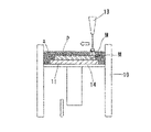
- FIG. 1A a process diagram illustrating a process of a method for manufacturing an additive product according to an embodiment of the present invention.
- FIG. 1B a process diagram illustrating a process of a method for manufacturing an additive product according to an embodiment of the present invention.
- FIG. 1C a process diagram illustrating a process of a manufacturing method of an additive product.
- FIG. 2A a process diagram illustrating a process of a manufacturing method of an additive product.
- FIG. 2B a process diagram illustrating a process of a method for manufacturing an additive product.
- FIG. 2C a process diagram illustrating a process of a manufacturing method of an additive product.
- Top view of the test piece used for the tensile test A photograph showing the shape of the manufactured additional product.
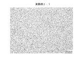
- a photograph showing the shape of a columnar addition product for producing a tensile test piece An optical microscope image in a vertical cross section of the manufactured additive product (Example 1-1).
- An optical microscope image in a vertical cross section of the manufactured additive product Example 2-1).
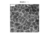
- An optical microscope image in a vertical cross section of the manufactured additive product Example 3-1).
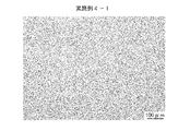
- An optical microscope image in a vertical cross section of the manufactured additive product Example 4-1).
- An optical microscope image in a vertical cross section of the manufactured additive product Example 5-1).
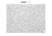
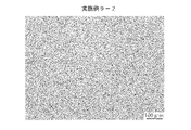
- An optical microscope image in a vertical cross section of the manufactured additive product Example 6-1).
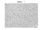
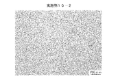
- An optical microscope image in a vertical cross section of the manufactured additive product (Example 7-1). An optical microscope image in a vertical cross section of the manufactured additive product (Example 8-1). An optical microscope image in a vertical cross section of the manufactured additive product (Example 9-2). An optical microscope image in a vertical cross section of the manufactured additive product (Example 10-2). An optical microscope image in a vertical cross section of the manufactured additive product (Example 11-2). An optical microscope image in a vertical cross section of the manufactured additive product (Example 12-2). An optical microscope image in a vertical cross section of the manufactured additive product (Comparative Example 1-1). An optical microscope image in a vertical cross section of the manufactured additive product (Comparative Example 2-1).
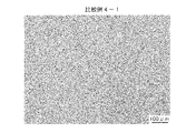
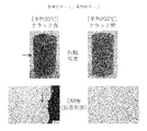
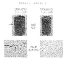
- An optical microscope image in a vertical cross section of the manufactured additive product (Comparative Example 3-1). An optical microscope image in a vertical cross section of the manufactured additive product (Comparative Example 4-1). An optical microscope image in a vertical cross section of the manufactured additive product (Comparative Example 5-1). External photographs of additional products manufactured at preheating temperatures of 35 ° C. and 200 ° C. and optical microscope images in vertical cross sections (Reference Example 9-1, Example 9-2). External photographs of additional products manufactured at preheating temperatures of 35 ° C. and 200 ° C. and optical microscope images in vertical cross sections (Reference Example 10-1, Example 10-2). External photographs of additional products manufactured at preheating temperatures of 35 ° C. and 200 ° C. and optical microscope images in vertical cross sections (Reference Example 11-1 and Example 11-2).
- the graph which shows the change of the Vickers hardness of an addition product by heat treatment (Example 7-1).
- the graph which shows the change of the Vickers hardness of an addition product by heat treatment (Example 8-1).
- the graph which shows the change of the Vickers hardness of an addition product by heat treatment (Example 9-2).
- the graph which shows the change of the Vickers hardness of an addition product by heat treatment (Example 10-2).
- the graph which shows the change of the Vickers hardness of an addition product by heat treatment Example 11-2).
- the graph which shows the change of the Vickers hardness of an addition product by heat treatment (Example 12-2).
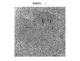
- a scanning transmission electron microscope (STEM) bright field image in a horizontal cross section of the manufactured additional product (Example 1-1).
- a scanning transmission electron microscope (STEM) bright field image in a horizontal cross section of the manufactured additional product (Example 2-1).
- a scanning transmission electron microscope (STEM) bright field image in a horizontal cross section of the manufactured additional product (Example 5-1).
- Scanning transmission electron microscope (STEM) high-angle annular dark-field image in a horizontal cross section of the manufactured additional product (Example 7-1).
- Scanning transmission electron microscope (STEM) high-angle annular dark-field image in a horizontal cross section of the manufactured additional product Example 8-1).
- Scanning transmission electron microscope (STEM) high-angle annular dark-field image in a horizontal cross section of the manufactured additional product (Example 11-2).
- Scanning transmission electron microscope (STEM) bright field image in a horizontal cross section of the manufactured additional product (Example 12-2).
- the present invention is an invention relating to an aluminum alloy powder for producing an additional product (hereinafter referred to as "metal powder for additional production"), an additional product using the same, and a method for producing the same.
- metal powder for additional production an additional product for producing an additional product
- metal powder for additional production an additional product using the same
- method for producing the same does not limit the scope of the invention of the present disclosure.
- the metal powder for additional manufacturing corresponds to toner and ink in a normal two-dimensional printer.
- This metal powder for additional production contains aluminum (Al) as a main component and contains at least one selected from iron (Fe), manganese (Mn), chromium (Cr), nickel (Ni) and zirconium (Zr). It is an aluminum alloy powder.
- the content of at least one selected from iron, manganese, chromium, nickel and zirconium is 0.20% by mass or more, preferably 1% by mass or more, preferably 2% by mass or more, and more preferably 4% by mass or more. It is preferable, 5% by mass or more is more preferable, and 7% by mass or more is particularly preferable. Further, it is 13% by mass or less, more preferably 9% by mass or less, still more preferably 8% by mass or less. When the content is within these ranges, the addition product produced by using the metal powder for addition production can achieve both high relative density, excellent high temperature strength and high temperature Young's modulus.
- the amount is more than the above range, the melting point of the powder becomes high, which may make it difficult to manufacture the metal powder for additional production. If it is less than the above range, it is highly possible that the high temperature strength, particularly the high temperature 0.2% proof stress, of the additive product produced by using the metal powder for additive production is not sufficiently improved.
- the total content of iron, manganese, chromium, nickel and zirconium is 0.20% by mass or more, preferably 1% by mass or more, preferably 2% by mass or more, and more preferably 4% by mass or more. 5% by mass or more is more preferable, and 10% by mass or more is particularly preferable. Further, it is 13% by mass or less, preferably 12.5% by mass or less, and more preferably 12% by mass or less.
- the addition product produced by using the metal powder for addition production can achieve both high relative density, excellent high temperature strength, and high temperature Young's modulus. If the amount is more than the above range, the melting point of the powder becomes high, which may make it difficult to manufacture the metal powder for additional production. On the other hand, if it is less than the above range, it is highly possible that the high temperature strength, particularly the high temperature 0.2% proof stress, of the additive product produced by using the metal powder for additive production is not sufficiently improved.
- the iron content of this metal powder for additional production is preferably less than 4.5% by mass, more preferably 3% by mass or less, and further preferably 2% by mass or less. If iron is contained in an amount of 4.5% by mass or more, the additive product produced by using the metal powder becomes significantly brittle, and cracks such as interlayer cracks may occur.
- the metal powder for additional manufacturing may further contain silicon.
- the silicon content is preferably less than 1% by mass, preferably less than 0.5% by mass. If the content is 1% by mass or more, the high-temperature strength and ductility of the additive product produced by using the metal powder may decrease, and further, cracks such as solidification cracks may occur.
- the metal powder for additional manufacturing may contain a small amount of impurity elements.
- the impurity element may be an element (unavoidable impurity) inevitably mixed in during the production of the aluminum alloy powder, or may be a modified element intentionally added.
- the content of the impurity element is not particularly limited, but is preferably 2% by mass or less, more preferably 1% by mass or less, further preferably 0.5% by mass or less, and particularly preferably 0.2% by mass or less.
- the impurity element examples include magnesium (Mg), copper (Cu), zinc (Zn), lithium (Li), silicon (Si), iron (Fe), manganese (Mn), chromium (Cr), and nickel.
- Ni Titanium (Ti), Calcium (Ca), Sodium (Na), Strontium (Sr), Yttrium (Y), Niob (Nb), Molybdenum (Mo), Tungsten (W), Antimon (Sb), Berylium (Be), phosphorus (P), vanadium (V), tin (Sn), lead (Pb), bismuth (Bi), molybdenum (Co), silver (Ag), gallium (Ga), scandium (Sc), cerium. (Ce), boron (B), carbon (C), nitrogen (N), oxygen (O) and the like can be mentioned.
- the content of each element in the metal powder for additional production can be measured by ICP emission spectroscopic analysis method, inert gas melting-infrared absorption method, or the like.
- the particle size of the metal powder for additional production is not particularly limited, but the volume-based average particle diameter (median diameter d 50 ) is preferably 1 ⁇ m or more, more preferably 5 ⁇ m or more, further preferably 10 ⁇ m or more, and particularly preferably 15 ⁇ m or more. preferable. If the average particle size is less than 1 ⁇ m, the fluidity of the powder is lowered, and there is a possibility that a uniform powder layer cannot be formed in the manufacturing process of the additive product. On the other hand, the average particle size is preferably 200 ⁇ m or less, more preferably 150 ⁇ m or less, further preferably 100 ⁇ m or less, and particularly preferably 60 ⁇ m or less. If the average particle size exceeds 200 ⁇ m, the powder may get caught in the squeegee during additional manufacturing and cannot be easily spread.
- the average circularity of the metal powder for additional manufacturing is not particularly limited, but is preferably 0.9 or more and 1.0 or less. If the average circularity is less than 0.9, the fluidity of the powder may decrease and a uniform powder layer may not be formed in the addition manufacturing process.
- the amount of oxygen contained in the metal powder for additional production is not particularly limited, but is preferably 0.001% by weight or more. Further, it is preferably 0.5% by weight or less, and more preferably 0.2% by weight or less. If the amount of oxygen exceeds this range, defects due to oxygen may occur in the added product and the mechanical properties may deteriorate, and if the amount of oxygen is less than this range, there is a risk that the powder spontaneously ignites.
- the amount of water contained in the metal powder for additional production is not particularly limited, but is preferably 0.001% by weight or more. Further, 0.5% by weight or less is preferable, and 0.2% by weight or less is more preferable. If the water content exceeds this range, gas defects may occur in the additional product and the mechanical properties may deteriorate, and it is industrially very difficult and unrealistic to keep the water content below this range. be.
- the metal powder for additional production can be produced by, for example, a gas atomization method or a water atomization method, but it can also be produced by a rotating electrode method, a plasma atomization method, a centrifugal atomization method, a mechanical alloying method, a chemical process, or the like. can do.
- the additional product of the present invention forms a metal layer by solidifying the metal powder for additional production at a predetermined position in the first step of forming the powder layer containing the metal powder for additional production and the powder layer.
- a second step is included, and the first step and the second step are sequentially repeated, and the metal layer is manufactured by stacking and joining a plurality of layers.
- the powder bed melt-bonding method which is a kind of addition manufacturing method, is used, but other addition manufacturing methods may be used, and for example, a directed energy deposition method can also be used.
- an addition manufacturing method by an indirect method such as a binder injection method or a fused deposition modeling method may be used.
- the metal powder a for additional manufacturing is placed on the base material 11 placed on the stage 14 in the chamber 10.
- the first step of supplying and forming the powder layer P containing the metal powder a for additional production on the base material 11 is performed.
- the powder layer P having a desired thickness t can be formed.
- the laser light scanning device 13 irradiates an arbitrary region on the surface of the metal powder layer P with laser light to heat the metal powder in the irradiated portion.
- the metal powder in the laser beam irradiated portion is melted or sintered and solidified, and as shown in FIG. 1C, the metal layer M is formed by irradiating the metal powder along a desired scanning path. Two steps are performed.
- the position of the stage 14 is moved downward by a predetermined thickness, and the squeegee 12 is moved in the horizontal direction (direction of arrow A), whereby the metal for additional manufacturing is placed on the metal layer M.
- the first step of supplying the powder a and forming the powder layer P containing the metal powder a for additional production on the base material 11 is performed again.
- the laser light scanning device 13 irradiates an arbitrary region on the surface of the metal powder layer P with laser light to heat the metal powder in the irradiated portion.
- the metal powder in the laser beam irradiated portion is melted or sintered and solidified, and as shown in FIG.
- the metal layer M is formed by irradiating the laser beam along the desired scanning path, and the second metal layer M is formed. The process is repeated. At this time, when the powder layer P is melted or solidified by sintering to form the metal layer M, it is joined to the previously formed lower metal layer M, so that the newly formed metal layer M is formed. Will be integrated with the underlying metal layer M.
- an additional product M1 in which a plurality of metal layers M are stacked and joined is manufactured.
- the additional product formed by stacking and joining the plurality of layers can be modeled based on, for example, slice data converted from the three-dimensional shape data of the target additional product by three-dimensional CAD.
- the slice data is the shape data of each cross section obtained by dividing the three-dimensional shape data of the additional product into a plurality of upper and lower layers with a predetermined laminated thickness t.
- the base material 11 is moved up and down using the stage 14 based on the predetermined stacking thickness t, and the laser beam is applied to a predetermined region based on the slice data for each metal powder layer P to be laminated in the vertical direction.
- the metal powder is locally melted or sintered and solidified by being irradiated with light, and an additional product having a desired shape can be formed.
- the irradiation conditions when irradiating the metal powder layer P with the laser beam are within the range of 10,000 W or less if the output is, for example.
- the scanning speed can be adjusted appropriately within the range of 30,000 mm / s or less, and the scanning interval can be adjusted within the range of 50 mm or less.
- the laminated thickness t can be appropriately adjusted within a range of, for example, 10 mm or less.
- the volumetric energy density under the optimum laser beam irradiation conditions for precisely manufacturing the additional product of the present invention is not particularly limited, but may be 30 J / mm 3 or more and 150 J / mm 3 or less. It is more preferably 40 J / mm 3 or more and 120 J / mm 3 or less, and further preferably 45 J / mm 3 or more and 100 J / mm 3 or less. If it is lower than the above range, void defects due to unmelting may occur inside the added product. If the temperature is higher than the above range, spherical gas pores may be generated inside the additional product by entraining hydrogen derived from moisture adhering to the atmospheric gas or powder.
- laser light can be used as a heat source for melting and solidifying the metal powder
- the means is not limited to laser light, and for example, an electron beam or plasma may be used.
- the metal layer, the powder layer and the additional product may be preheated in the first step and the second step.
- the preheating temperature is preferably 50 ° C. or higher, more preferably 150 ° C. or higher. Further, 500 ° C. or lower is preferable, 400 ° C. or lower is more preferable, and 250 ° C. or lower is further preferable. Preheating at a temperature of less than 50 ° C. does not sufficiently suppress cracks (delamination), and preheating at a temperature of over 500 ° C. causes the fine structure of the added product to disappear and the mechanical properties to deteriorate.
- an electric heater attached to the modeling platform or the lower part of the base plate is usually used, but a ceramic heater, high-frequency heating, or the like may be used. Further, the heat source such as a laser beam or an electron beam may be scanned and heated.
- the production method of the present invention may further include a third step of heat-treating the additional product after the second step.
- a third step of heat-treating the additional product in the heat treatment step of the third step, 200 ° C. or higher is preferable, and 250 ° C. or higher is more preferable. Further, 650 ° C. or lower is preferable, 500 ° C. or lower is more preferable, and 450 ° C. or lower is further preferable.
- Heat treatment below 200 ° C does not sufficiently improve the strength, and heat treatment at a temperature above 650 ° C causes the microstructure of the additional product to disappear and the mechanical properties to deteriorate, or a part of the additional product to melt and the additional product to melt. The shape may change.
- a solution heat treatment (solid solution heat treatment) may be carried out before the heat treatment.
- the furnace used for the heat treatment is usually an atmospheric furnace, but an atmospheric furnace may be used for treatment in an inert gas atmosphere such as nitrogen or argon or in a reducing gas atmosphere such as hydrogen.
- the time for performing the heat treatment is preferably 0.1 hours or more, preferably 0.5 hours or more, and more preferably 1 hour or more. Further, 1000 hours or less is preferable, 500 hours or less is preferable, 100 hours or less is more preferable, and 30 hours or less is further preferable. If it is shorter than 0.1 hour, the strength of the additive product may not be sufficiently improved. On the other hand, if it is longer than 1000 hours, the strength of the additive product may decrease due to overaging.
- the additive product of the present invention is composed of an aluminum alloy having a specific composition constituting the metal powder for additive production. That is, this addition product contains at least one of iron, manganese, chromium, nickel and zirconium as an alloying element in aluminum.
- the content of at least one selected from iron, manganese, chromium, nickel and zirconium is 0.20% by mass or more, preferably 1% by mass or more, preferably 2% by mass or more, and more preferably 4% by mass or more. It is preferable, 5% by mass or more is more preferable, and 7% by mass or more is particularly preferable.
- the additive product is 13% by mass or less, more preferably 9% by mass or less, still more preferably 8% by mass or less.
- the additive product can achieve both high relative density, excellent high temperature strength and high temperature Young's modulus. If it is more than the above range, the melting point of the alloy becomes high, which makes it difficult to manufacture the additional product, and the ductility of the additional product is significantly reduced. If it is less than the above range, it is highly possible that the high temperature strength of the additive product, particularly the high temperature 0.2% proof stress, is not sufficiently improved.
- the total content of iron, manganese, chromium, nickel and zirconium in this additional product is 0.20% by mass or more, preferably 1% by mass or more, preferably 2% by mass or more, and 4% by mass or more. Is more preferable, 5% by mass or more is further preferable, and 10% by mass or more is particularly preferable. Further, it is 13% by mass or less, preferably 12.5% by mass or less, and more preferably 12% by mass or less. When the total content is within these ranges, the additive product can achieve both high relative density, excellent high temperature strength and high temperature Young's modulus.
- the melting point of the alloy becomes high, which makes it difficult to manufacture the additional product, and the ductility of the additional product is significantly reduced. If it is less than the above range, it is highly possible that the high temperature strength of the additive product, particularly the high temperature 0.2% proof stress, is not sufficiently improved.
- the iron content of this additional product is preferably less than 4.5% by mass, more preferably 3% by mass or less, and even more preferably 2% by mass or less. If iron is contained in an amount of 4.5% by mass or more, the additive product having the composition is remarkably brittle, and cracks such as interlayer cracks may occur.
- the additional product may further contain silicon.
- the silicon content is preferably less than 1% by mass, preferably less than 0.5% by mass. If the content is 1% by mass or more, the high-temperature strength and ductility of the additive product having the composition may decrease, and further, cracks such as solidification cracks may occur.
- the additional product may contain a small amount of impurity elements.
- the impurity element may be an element (unavoidable impurity) inevitably mixed in during the production of the aluminum alloy powder, or may be a modified element intentionally added.
- the content of the impurity element is not limited, but is preferably 2% by mass or less, more preferably 1% by mass or less, more preferably 0.5% by mass or less, and particularly preferably 0.2% by mass or less.
- the impurity element examples include magnesium (Mg), copper (Cu), zinc (Zn), lithium (Li), silicon (Si), iron (Fe), manganese (Mn), chromium (Cr), and nickel.
- Ni Titanium (Ti), Calcium (Ca), Sodium (Na), Strontium (Sr), Yttrium (Y), Niob (Nb), Molybdenum (Mo), Tungsten (W), Antimon (Sb), Berylium (Be), phosphorus (P), vanadium (V), tin (Sn), lead (Pb), bismuth (Bi), molybdenum (Co), silver (Ag), gallium (Ga), scandium (Sc), cerium. (Ce), boron (B), carbon (C), nitrogen (N), oxygen (O) and the like can be mentioned.
- the content of each element in the additive product is the same as the method for measuring the content of each element in the metal powder for additive production, such as ICP emission spectroscopic analysis method and Inactive gas melting-infrared absorption method. Can be measured by using.
- the additive product according to the present invention has a relative density of 95% or more and 100% or less.
- the relative density of the additive product is preferably 98% or more, more preferably 99% or more, and even more preferably 99.5% or more. If the relative density does not meet this range, the mechanical properties of the additive product will be significantly degraded.
- This relative density is the area ratio of the metal part excluding the void part by binarizing the optical microscope image (magnification 100 times) in an arbitrary vertical (parallel to the stacking direction) cross section near the center of the addition product. Is calculated as. The higher the relative density, the more desirable it is for improving the mechanical strength, ductility and thermal / electrical conductivity of the additive product.
- the additional product has a high temperature tensile strength of 140 MPa or more at a test temperature of 150 ° C., a high temperature tensile strength of 130 MPa or more at a test temperature of 200 ° C., and a high temperature tensile strength of 115 MPa or more at a test temperature of 250 ° C.
- the additional product has a high temperature 0.2% proof stress of 115 MPa or more at a test temperature of 150 ° C., a high temperature 0.2% proof stress of 105 MPa or more at a test temperature of 200 ° C., and a high temperature 0.2% proof stress of 95 MPa or more at a test temperature of 250 ° C. It has a high temperature 0.2% proof stress, a high temperature 0.2% proof stress of 75 MPa or more at a test temperature of 300 ° C., and a high temperature 0.2% proof stress of 30 MPa or more at a test temperature of 350 ° C.
- the additional product can exhibit heat resistance superior to that of the prior art. Among these, if the high temperature 0.2% proof stress at the test temperature of 350 ° C. satisfies the above condition, there is a tendency that more sufficient improvement in heat resistance can be obtained.
- the additional product has a high-temperature Young's modulus of 59 GPa or more at a test temperature of 200 ° C., a high-temperature Young's modulus of 52 GPa or more at a test temperature of 250 ° C., and a high-temperature Young's modulus of 34 GPa or more at a test temperature of 300 ° C. It has a high-temperature Young's modulus of 29 GPa or more at a test temperature of 350 ° C. By having such a high temperature Young's modulus, the additional product can exhibit a rigidity superior to that of the prior art in a high temperature region.
- the high-temperature tensile strength, high-temperature 0.2% proof stress, and high-temperature Young's modulus of the added product are measured by a tensile test in a high-temperature atmosphere.
- the tensile test piece in the high temperature tensile test the one having the shape shown in FIG. 4 is used. This tensile test piece is held at each measurement temperature for 1 hour or more before the test is carried out.
- the strain rate in the high temperature tensile test is 0.3% / min up to 0.2% proof stress, and 7.5% / min until breakage after reaching 0.2% proof stress.
- the elongation at room temperature is preferably 9% or more, more preferably 15% or more.
- the content is 9% or more, sudden damage to the added product can be prevented when a load is applied, and good toughness and impact energy absorption characteristics can be exhibited.
- the above-mentioned breaking elongation at room temperature of the additive product is measured by a tensile test at room temperature.
- a tensile test piece in the tensile test the one having the shape shown in FIG. 4 is used.
- the strain rate in the tensile test is 0.3% / min up to 0.2% proof stress, and 7.5% / min until breakage after reaching 0.2% proof stress.
- the quenching solidification process by such an addition manufacturing method is applied to the aluminum-transition metal alloy powder, a supersaturated solid solution or a non-equilibrium phase is generated by the forced solid solution of the transition metal element, and the heat treatment after modeling is performed.
- This makes it possible to form a structure in which a transition metal-based compound that is stable at high temperature is finely dispersed.
- some transition metal elements can be stably dissolved in aluminum up to high temperatures.
- the addition product in the present invention exhibits excellent mechanical properties at room temperature and high temperature by strengthening dispersion / precipitation with a transition metal compound, strengthening a structural composite and strengthening grain boundaries, and strengthening the solid solution of a transition metal element. can do.
- the particle size distribution of the powder was measured by the laser diffraction / scattering method, and the particle size of 50% cumulative from the fine particle side in the volume-based particle size distribution was taken as the average particle size.
- the average particle diameter is also referred to as a median diameter "d 50 ".
- the density by the Archimedes method can be measured according to "JIS Z 2501: Sintered metal material-Density, oil content and open porosity test method". Based on the results, the optimum conditions for each metal powder for addition manufacturing were determined as the conditions for obtaining the addition product having the highest density. Further, the value of Ed under the optimum conditions was calculated using the above formula.
- the relative density of the additional product was obtained by binarizing an optical microscope image (magnification 100 times) of an arbitrary vertical cross section near the center of the cylindrical (diameter 8 mm, height 15 mm) additional product, and excluding voids. Calculated as the area ratio of the metal part. Those having cracks were not measured.
- Tensile strength, 0.2% proof stress, elongation at break are all grade 1 or higher tensile test equipment based on "JIS B 7721: Tensile tester / compression tester-calibration method and verification method for force measurement system”. Was measured using. Tensile tests at room temperature and high temperature were carried out based on "JIS Z 2241: 2011: Metallic material tensile test method” and "JIS G 0567: 2020: High temperature tensile test method for steel materials and heat-resistant alloys", respectively. The tensile test piece used was made by turning into the shape shown in FIG.
- each part of the test piece 20 is as follows: the total length L of the test piece 20 is 80 mm, the length L1 of the main body 22 is 30 mm ⁇ 0.1 mm, the diameter D1 of the main body 22 is 6 mm ⁇ 0.05 mm, and the shoulder 23.
- the radius of curvature R was 4.5 mm, the length L2 of the grip portion 21 was 15 mm, and the diameter D of the grip portion 21 was 10 mm. Then, this test piece 20 was held at each test temperature for 1 hour before the tensile test at a high temperature was carried out, and then subjected to each test.
- Tensile strength The tensile strength at room temperature was measured by the following method after the addition manufacturing, before the heat treatment (as it was shaped), or after cooling to room temperature after the heat treatment. Further, before or after the heat treatment, the material was heated to 150 ° C., 200 ° C., 250 ° C., 300 ° C., and 350 ° C., and the high-temperature tensile strength was similarly measured by the following method. The test piece 20 was pulled using a tensile test device until it broke, and the tensile load during that period was measured at any time. The strain rate in the tensile test was 0.3% / min up to 0.2% proof stress, and 7.5% / min until breakage after reaching 0.2% proof stress.
- the brim portion 24 of the main body portion of the test piece 20 for the tensile test was used as the reference point, and the length L1 of the main body portion was used as the distance between the reference points.
- the strain rate in the tensile test was 0.3% / min up to 0.2% proof stress, and 7.5% / min until breakage after reaching 0.2% proof stress.
- the jig of the tensile test device gripped the grip portion 21 of the test piece 20 and adjusted so that a force was applied in the axial direction of the test piece 20. A nominal stress-nominal strain curve was obtained based on the above tensile load and displacement data of the distance between gauge points.
- the nominal strain was calculated as a percentage of the measured displacement of the distance between the gauge points divided by the initial distance between the gauge points measured prior to the test.
- the 0.2% proof stress value was calculated using the offset method described in "JIS Z 2241: 2011: Metallic Material Tensile Test Method".
- the breaking elongation at room temperature was measured by the following method.
- the brim portion 24 of the main body portion of the test piece 20 for the tensile test was used as a reference point, and the length L1 of the main body portion was defined as the distance between the reference points.
- the distance between the gauge points before the test was measured and used as the initial distance between the gauge points.
- the fracture surfaces are butted while being careful so that the center lines of both fracture fragments of the test piece 20 are on a straight line, and the distance between the gauge points after fracture is measured. bottom.
- the fracture elongation was calculated as a percentage obtained by dividing the difference between the distance between the gauge points after the fracture and the distance between the initial gauge points by the initial distance between the gauge points.
- the strain rate in the tensile test was 0.3% / min up to 0.2% proof stress, and 7.5% / min until fracture after reaching 0.2% proof stress.
- Young's modulus After the addition production, before the heat treatment, or after the heat treatment, the product was heated to 150 ° C., 200 ° C., 250 ° C., 300 ° C., and 350 ° C., and the high-temperature Young's modulus was measured by the following method.
- the test piece 20 was pulled using a tensile test device until it broke, and the tensile load during that period was measured at any time. At the same time, the amount of displacement of the distance between the gauge points of the test piece during the test was measured at any time using an extensometer.
- the brim portion 24 of the main body of the test piece 20 for the tensile test was used as a reference point, and the length L1 was used as the distance between the reference points.
- the strain rate in the tensile test was 0.3% / min up to 0.2% proof stress, and 7.5% / min until breakage after reaching 0.2% proof stress.
- the jig of the tensile test device gripped the grip portion 21 of the test piece 20 and adjusted so that a force was applied in the axial direction of the test piece 20. A nominal stress-nominal strain curve was obtained based on the above tensile load and displacement data of the distance between gauge points.
- the nominal strain was calculated as a percentage of the measured displacement of the distance between the gauge points divided by the initial distance between the gauge points measured prior to the test.
- Young's modulus was calculated as the slope of the rising straight line in the nominal stress-nominal strain curve immediately after the start of the test.
- Examples 1-1 to 8-1 Reference Examples 9-1 to 12-1, Examples 1-2 to 12-2, Comparative Examples 1-1 to 5-1, 1-2 to 5-2
- an addition product was produced by an addition production method (laser laminated molding method) of a powder bed melt-bonding method using a laser as a heat source.
- Each metal powder for addition production was prepared by a nitrogen gas atomizing method.
- the laser laminated molding apparatus used is EOSINT M280 manufactured by EOS of Germany, and a ytterbium (Yb) fiber laser (laser wavelength: about 1070 nm) having a spot diameter of about 0.1 mm and an output of 400 W class is mounted on the heat source.
- Yb ytterbium
- the conditions (optimum conditions) for obtaining the addition production having the highest density were selected for each powder. Further, the metal layer, the powder layer and the additional product are preheated to 35 ° C. or 200 ° C. before modeling by using an electric heater attached to the lower part of the modeling platform of the laser laminated modeling apparatus, and the modeling platform is heated during modeling. This was done while monitoring the temperature of the thermocouple installed inside and controlling the temperature. Tables 2 and 3 show the characteristics of the manufactured additional products.
- FIGS. 5A and 5B an example of the shape of the manufactured additional product is shown in FIGS. 5A and 5B.
- the optical microscope images of the manufactured additional product having the shape of FIG. 5A in the vertical cross section are shown in FIGS. 6A to 6D, 7A to 7D, 8A to 8D, 9A to 9C, and 10A to 10A. Shown in 10B.
- Photographs of the appearance of the additional product having the shape of FIG. 5A and an optical microscope (OM) image in a vertical cross section are shown in FIGS. 11A to 11D.
- FIGS. 12A to 12D changes in Vickers hardness of the added product due to heat treatment are shown in FIGS. 12A to 12D, FIGS. 13A to 13D, and FIGS. 14A to 14D.
- the plots (black circles) at the left ends (0 hours) of FIGS. 12A to 12D, 13A to 13D, and 14A to 14D show the hardness values of the added product as it is formed (without heat treatment).
- a scanning transmission electron microscope eg STEM
- FIGS. 15A to 15G A bright-field image or a high-angle annular dark-field image is shown in FIGS. 15A to 15G.
- Reference Examples 9-1, 10-1, 11-1, and 12-1 become Examples 9-2, 10-2, 11-2, and 12-2 by setting the preheating temperature to 200 ° C. Therefore, from the viewpoint of having relevance to Examples 9-2, 10-2, 11-2, and 12-2, the reference examples were used instead of the comparative examples, and the numbers were also combined with the numbers of the corresponding examples. ..
- the additional product of each example is a high-density body having a relative density of 99.5% or more, and has excellent high-temperature strength (high-temperature tensile strength) in a high-temperature range of 150 ° C. or higher. , High temperature 0.2% proof stress) and high temperature Young's modulus, and it was found that it has sufficient normal temperature tensile strength, normal temperature 0.2% proof stress, and normal temperature breaking elongation. On the other hand, it is clear that Comparative Examples 1 to 3 and 5 have cracks and do not have sufficient strength.
- Comparative Example 4 is a high-density body having no cracks and having a relative density of 99.5% or more, but has a high-temperature tensile strength of 300 ° C. or higher, a high-temperature 0.2% proof stress, a high-temperature Young's modulus of 200 ° C. or higher, and a high-temperature Young's modulus of 200 ° C. or higher. It was found that the elongation at room temperature was not preferable. Further, as shown in FIGS.
- Example 15A to 15G from the bright field (BF) image and the high angle annular dark field (HAADF) image of the scanning transmission electron microscope (STEM) in the horizontal cross section of the augmented product, Example 1-1, In 2-1 in the aluminum matrix, fine crystallization phases and precipitation phases are dispersed at the cell boundaries and grain boundaries, and aluminum and iron (Example 1-1) and aluminum and manganese (Example 2), respectively. It can be judged that it is a transition metal-based compound of -1). Since the diffusion rate of transition metal elements in aluminum is slow, it is considered that these transition metal compounds can exist stably up to high temperatures.
- Example 5-1 the presence of a clear precipitated phase was not confirmed, and analysis by STEM-EDS revealed that chromium tended to dissolve in the matrix phase. Since the diffusion rate of chromium in aluminum is even slower than that of iron and manganese, it is considered that the solid solution chromium can stably contribute to the solid solution strengthening up to a high temperature, and thus the high temperature strength and the high temperature Young's modulus could be improved.
- Example 7-1 a compound of aluminum and zirconium (Al 3 Zr) was finely precipitated (up to 5 nm) in the aluminum matrix, and chromium was solid-dissolved as in Example 5. It is considered that the high temperature strength and the high temperature Young's modulus could be improved mainly by strengthening the solid solution of chromium and strengthening the precipitation with Al 3 Zr.
- Example 8-1 dispersion / precipitation strengthening by a network transition metal-based compound of aluminum and manganese crystallized / precipitated in the cell boundary and the aluminum matrix, structural composite strengthening and grain boundary strengthening, and manganese / chromium It is considered that the high temperature strength and the high temperature Young's modulus could be improved by the solid solution strengthening.
- Example 11-2 various transition metal-based compounds containing petals, plates, and granules mainly containing aluminum, manganese, chromium, and iron are used for dispersion / precipitation strengthening, grain boundary strengthening, and systematic composite strengthening, and various transitions. It is considered that the high temperature strength and the high temperature young rate could be improved by strengthening the solid solution with metal.
- Example 12-2 dispersion / precipitation strengthening and systematic composite strengthening of aluminum and nickel reticulated transition metal-based compounds crystallized / precipitated in the cell boundary and the aluminum matrix, and a compound of aluminum and zirconium (Al). It is considered that the high temperature strength and the high temperature young rate could be improved by strengthening the precipitation by 3 Zr).
- Examples 3-1, 4-1 and 6-1, 9-2, and 10-2 are addition products made of an aluminum alloy containing a transition metal element, and thus the transition metal is the same as described above. It is presumed that the high-temperature strength and high-temperature Young's ratio could be improved by strengthening the dispersion / precipitation with the system compound, strengthening the structural composite and strengthening the grain boundary, and strengthening the solid solution of the transition metal element.
Landscapes
- Engineering & Computer Science (AREA)
- Chemical & Material Sciences (AREA)
- Materials Engineering (AREA)
- Manufacturing & Machinery (AREA)
- Mechanical Engineering (AREA)
- Metallurgy (AREA)
- Organic Chemistry (AREA)
- Physics & Mathematics (AREA)
- Plasma & Fusion (AREA)
- Automation & Control Theory (AREA)
- Powder Metallurgy (AREA)
Abstract
Description
前記付加製造用金属粉末は、通常の2次元プリンタにおけるトナー、インクに相当する。この付加製造用金属粉末は、アルミニウム(Al)を主成分とし、鉄(Fe)、マンガン(Mn)、クロム(Cr)、ニッケル(Ni)及びジルコニウム(Zr)から選ばれる少なくとも1種を含有するアルミニウム合金粉末である。
次に、前記付加製造用金属粉末を用いた付加製造物の製造方法について説明する。
本発明の付加製造物は、前記付加製造用金属粉末を含む粉末層を形成する第1工程と、前記粉末層において、所定位置の前記付加製造用金属粉末を固化させることにより金属層を形成する第2工程を含み、この第1工程と第2工程とが順次繰り返され、前記金属層を複数層積み上げて接合されることにより製造される。
本発明においては、付加製造法の一種である粉末床溶融結合法を用いているが、それ以外の付加製造法を利用してもよく、例えば、指向性エネルギー堆積法を利用することもできる。さらには、結合剤噴射法や熱溶解積層法のような間接法による付加製造法を用いてもよい。
続いて、図2Bに示すように、レーザ光走査装置13により、金属粉末層P表面の任意の領域にレーザ光を照射し、この照射部分の金属粉末を加熱する。これにより、レーザ光照射部分の金属粉末が溶融もしくは焼結して固化し、図2Cに示すように、レーザ光を所望の走査経路に沿って照射することにより金属層Mが造形され、第2工程が再度行われる。このとき、粉末層Pが溶融もしくは焼結により固化して金属層Mが造形される際には、先に造形された下層の金属層Mと接合されるので、新たに造形される金属層Mは下層の金属層Mと一体化することになる。
この複数層積み上げて接合された付加製造物は、例えば、目的とする付加製造物の三次元CADによる立体形状データから変換されたスライスデータに基づき造形することができる。スライスデータは、付加製造物の立体形状データを所定の積層厚さtで上下複数の層に分割した各断面の形状データである。所定の積層厚さtに基づいて基材11をステージ14を用いて上下動させるとともに、上下方向に複数積層される各金属粉末層Pに対して、前記スライスデータに基づいてレーザ光が所定領域に照射されることで、局所的に金属粉末が溶融もしくは焼結して固化し、所望の形状を有する付加製造物を造形することができる。
Ed=P/(V・s・t)
で算出される体積エネルギー密度Ed(J/mm3)を、金属粉末の組成、粒度分布や粉体形状などの粉体特性ごとに最適化した条件により金属粉末に照射することで、高い相対密度を有する付加製造物が得られることがわかっている。
本発明の付加製造物は、前記の付加製造用金属粉末を構成する特定組成のアルミニウム合金により構成される。すなわち、この付加製造物は、アルミニウムに合金元素として、鉄、マンガン、クロム、ニッケル及びジルコニウムの少なくともいずれか1種を含有する。
この鉄、マンガン、クロム、ニッケル及びジルコニウムから選ばれる少なくとも1種の含有量は、0.20質量%以上であり、1質量%以上がよく、2質量%以上が好ましく、4質量%以上がより好ましく、5質量%以上がさらに好ましく、7質量%以上が特に好ましい。また、13質量%以下であり、9質量%以下がより好ましく、8質量%以下がさらに好ましい。含有量がこれらの範囲内であることにより、付加製造物は高い相対密度と優れた高温強度及び高温ヤング率を両立できる。上記範囲よりも多い場合、合金の融点が高くなることで付加製造物の製造が困難になり、かつ、付加製造物の延性が大幅に低下する。上記範囲よりも少ない場合、付加製造物の高温強度、特に高温0.2%耐力が十分に向上しない可能性が高い。
この相対密度は、付加製造物の中心部付近の任意の鉛直(積層方向に対して平行)断面における光学顕微鏡像(倍率100倍)を二値化して、空隙部分を除いた金属部分の面積割合として算出される。
相対密度は、付加製造物の機械強度、延性及び熱・電気伝導性の向上のためには、高いほど望ましい。
このような高温引張強さを有することにより、前記付加製造物は従来技術よりも優れた耐熱性を発揮することができる。
このような高温0.2%耐力を有することにより、前記付加製造物は従来技術よりも優れた耐熱性を発揮することができる。この中でも、試験温度350℃における高温0.2%耐力が上記の条件を満たすことにより、より十分な耐熱性の向上が得られる傾向がある。
このような高温ヤング率を有することにより、前記付加製造物は高温域において従来技術よりも優れた剛性を発揮することができる。
これに対し、前記のようなレーザ積層造形法等、レーザや電子ビーム等の照射を行う付加製造法を用いると、レーザや電子ビーム等の照射による急冷凝固に起因して、極めて速い冷却速度(103~106K/s)で造形できることが前記非特許文献1等に開示されている。そのため、アルミニウム-遷移金属系合金粉末に対して、このような付加製造法による急冷凝固プロセスを適用した場合、遷移金属元素の強制固溶により過飽和固溶体や非平衡相が生成し、造形後の熱処理により高温安定な遷移金属系化合物を微細分散した組織を形成することが可能となる。また、一部の遷移金属元素は高温まで安定的にアルミニウム中に固溶することができる。その結果、本発明における付加製造物は遷移金属系化合物による分散・析出強化、組織的複合強化及び粒界強化、並びに遷移金属元素の固溶強化等により、常温及び高温において優れた機械特性を発揮することができる。
[付加製造用金属粉末中の各元素の含有量]
ICP発光分光分析法により測定した。
レーザ回折散乱法により粉末の粒度分布を測定し、体積基準の粒度分布において微粒側から累積50%の粒子径を平均粒子径とした。なお、平均粒子径はメディアン径「d50」とも表記される。
付加製造におけるレーザ光の体積エネルギー密度(Ed(J/mm3))は、下記の式で算出した。
Ed=P/(V・s・t)
なお、レーザ光の出力P(W)、走査速度V(mm/s)、走査間隔s(mm)、積層厚さt(mm)である。
各付加製造用金属粉末に対して、レーザ光の出力P(W)、走査速度V(mm/s)、走査間隔s(mm)を変化させて付加製造物を作製し、作製した付加製造物の密度をアルキメデス法により測定した。アルキメデス法による密度は、「JIS Z 2501:焼結金属材料-密度、含油率及び開放気孔率試験方法」に準拠して測定できる。その結果を基に、最も高い密度の付加製造物が得られる条件として、各付加製造用金属粉末に対する最適条件を決定した。さらに、最適条件におけるEdの値を上記の式を用いて算出した。
光学顕微鏡を用いて、各実施例及び比較例で得られた図5Aの円柱形状(直径8mm、高さ15mm)の付加製造物の鉛直断面における光学顕微鏡像(倍率100倍)を撮影した。それらの結果を図6A~図6D、図7A~図7D、図8A~図8D、図9A~図9C、図10A~図10Bに示す。なお、付加製造物作製時のレーザ照射条件は、それぞれの付加製造用金属粉末に対して決定した最適条件を用いた。これらの画像を基に、付加製造物におけるクラックの有無を判定した。
付加製造物の相対密度は、円柱形状(直径8mm、高さ15mm)の付加製造物の中心部付近における任意の鉛直断面の光学顕微鏡像(倍率100倍)を二値化し、空隙部分を除いた金属部分の面積割合として算出した。
なお、クラックを有するものは、測定しなかった。
引張強さ、0.2%耐力、破断伸びは、いずれも、「JIS B 7721:引張試験機・圧縮試験機-力計測系の校正方法及び検証方法」に基づく等級1級以上の引張試験装置を使用して測定した。常温、高温における引張試験は、それぞれ、「JIS Z 2241:2011:金属材料引張試験方法」、「JIS G 0567:2020:鉄鋼材料及び耐熱合金の高温引張試験方法」に基づいて実施した。
用いた引張試験片は、図5Bに示す積層方向に対して垂直方向に作製した円柱形状(直径12mm、長さ80mm)の前記付加製造物から、図4に示す形状に旋削して作製した。
なお、試験片20の各部の寸法は、試験片20の全長Lが80mm、本体部22の長さL1が30mm±0.1mm、本体部22の直径D1が6mm±0.05mm、肩部23の曲率半径Rが4.5mm、把持部21の長さL2が15mm、把持部21の直径Dが10mmとした。
そして、この試験片20は、高温での引張試験実施前には各試験温度にて1時間保持された後、各試験に供された。
付加製造後、熱処理前(造形まま)、又は熱処理後に常温に冷却した後に、下記の方法で常温引張強さを測定した。また、熱処理前、又は熱処理後、150℃、200℃、250℃、300℃、350℃に加熱して、同様に下記の方法で高温引張強さを測定した。
前記試験片20を、引張試験装置を用いて、破断するまで引っ張り、その間の引張荷重を随時測定した。引張試験における歪み速度は、0.2%耐力まで0.3%/min、0.2%耐力に到達以降、破断まで7.5%/minとした。このとき、引張試験装置の冶具は、試験片20の把持部21を掴み、試験片20の軸方向に力が加わるように調整した。そして、最大引張荷重を試験前の本体部22の断面積(=π×D1×D1÷4)で除して、引張強さを算出した。
付加製造後、熱処理前、又は熱処理後に常温に冷却した後に、下記の方法で常温0.2%耐力を測定した。また、熱処理前、又は熱処理後、150℃、200℃、250℃、300℃、350℃に加熱して、同様に下記の方法で高温0.2%耐力を測定した。
前記試験片20を、引張試験装置を用いて、破断するまで引っ張り、その間の引張荷重を随時測定した。同時に、伸び計を用いて、試験中における試験片の標点間距離の変位量を随時測定した。このとき、引張試験用の試験片20の本体部のツバ部24を標点とし、本体部の長さL1を標点間距離とした。引張試験における歪み速度は、0.2%耐力まで0.3%/min、0.2%耐力に到達以降、破断まで7.5%/minとした。引張試験装置の冶具は、試験片20の把持部21を掴み、試験片20の軸方向に力が加わるように調整した。上記の引張荷重、標点間距離の変位のデータを基に、公称応力-公称歪み曲線を取得した。公称応力は、引張荷重を試験前の本体部22の断面積(=π×D1×D1÷4)で除して算出した。公称歪みは、測定した標点間距離の変位量の値を、試験前に測定した初期の標点間距離で除した百分率として算出した。0.2%耐力値は、「JIS Z 2241:2011:金属材料引張試験方法」に記載されたオフセット法を用いて算出した。
付加製造後、熱処理前、又は熱処理後に常温に冷却した後に、下記の方法で常温破断伸びを測定した。
まず、引張試験用の試験片20の本体部のツバ部24を標点とし、本体部の長さL1を標点間距離とした。試験前における標点間距離を計測して、初期の標点間距離とした。そして、試験片20について前記の引張試験を実施した後、試験片20の両破断片の中心線が一直線上になるように注意しながら破断面を突き合わせて、破断後の標点間距離を測定した。この破断後の標点間距離と初期の標点間距離との差を初期の標点間距離で除した百分率として、破断伸びを算出した。なお、引張試験における歪み速度は、0.2%耐力まで0.3%/min、0.2%耐力に到達以降、破断まで7.5%/minとした。
付加製造後、熱処理前、又は熱処理後、150℃、200℃、250℃、300℃、350℃に加熱して、下記の方法で高温ヤング率を測定した。
前記試験片20を、引張試験装置を用いて、破断するまで引っ張り、その間の引張荷重を随時測定した。同時に、伸び計を用いて、試験中における試験片の標点間距離の変位量を随時測定した。このとき、引張試験用の試験片20の本体部のツバ部24を標点とし、長さL1を標点間距離とした。引張試験における歪み速度は、0.2%耐力まで0.3%/min、0.2%耐力に到達以降、破断まで7.5%/minとした。引張試験装置の冶具は、試験片20の把持部21を掴み、試験片20の軸方向に力が加わるように調整した。上記の引張荷重、標点間距離の変位のデータを基に、公称応力-公称歪み曲線を取得した。公称応力は、引張荷重を試験前の本体部22の断面積(=π×D1×D1÷4)で除して算出した。公称歪みは、測定した標点間距離の変位量の値を、試験前に測定した初期の標点間距離で除した百分率として算出した。ヤング率は、試験開始直後の公称応力-公称歪み曲線における立ち上がり直線の傾きとして算出した。
各実施例で製造された付加製造物を、大気炉中にて200℃~550℃の温度に加熱し、1~30時間の熱処理を行った。
各温度において1、3、5、7、10、20、30時間経過後、炉外に取り出して常温まで冷却した後に、下記の方法で荷重0.2kgfにてビッカース硬度(Hv0.2)を測定した。
ビッカース硬度(Hv0.2)は、「JIS Z 2244:2009:ビッカース硬さ試験-試験方法」にしたがって測定した。
実施例で製造された付加製造物の水平(積層方向に対して垂直)断面を、走査型透過電子顕微鏡(STEM:Scanning Transmission Electron Microscope)を用いて観察した。
表1に示す各種の付加製造用金属粉末を用いて、レーザを熱源とする粉末床溶融結合方式の付加製造法(レーザ積層造形法)により付加製造物を作製した。各付加製造用金属粉末は、窒素ガスアトマイズ法により作製した。
使用したレーザ積層造形装置は、ドイツEOS社製のEOSINT M280であり、熱源にスポット径約0.1mm、出力400W級のイッテルビウム(Yb)ファイバーレーザ(レーザ波長:約1070nm)を搭載している。
付加製造時のレーザ照射条件(体積エネルギー密度(Ed))は、各粉末に対して、最も高い密度の付加製造物が得られる条件(最適条件)を選択した。
また、金属層、粉末層及び付加製造物の予熱は、前記レーザ積層造形装置の造形プラットホーム下部に取り付けた電熱ヒータを用いて、造形前に35℃又は200℃に加熱し、造形中も造形プラットホーム内部に取り付けた熱電対の温度をモニタリングしながら、当該温度に制御しながら行った。
製造された付加製造物の諸特性を表2、表3に示す。
また、製造された図5Aの形状の付加製造物の鉛直断面における光学顕微鏡像を、図6A~図6D、図7A~図7D、図8A~図8D、図9A~図9C、図10A~図10Bに示す。
また、参考例9-1、10-1、11-1、12-1、実施例9-2、10-2、11-2、12-2において、予熱温度35℃及び200℃にて製造された図5Aの形状の付加製造物の外観写真及び鉛直断面における光学顕微鏡(OM)像を、図11A~図11Dに示す。
さらに、熱処理による付加製造物のビッカース硬度の変化を図12A~図12D、図13A~図13D、図14A~図14Dに示す。なお、図12A~図12D、図13A~図13D、及び図14A~図14Dの左端(0時間)のプロット(黒丸)は、造形まま(熱処理なし)の付加製造物における硬度の値を示している。
さらにまた、製造された付加製造物(実施例1-1、2-1,5-1,7-1,8-1,11-2,12-2)の水平断面における走査型透過電子顕微鏡(STEM)明視野像又は高角環状暗視野像を図15A~図15Gに示す。
なお、参考例9-1、10-1、11-1、12-1は、予熱温度を200℃とすることにより、実施例9-2、10-2、11-2、12-2となったので、実施例9-2、10-2、11-2、12-2との関連性を有する観点から、比較例とせずに参考例とし、その番号も、該当実施例の番号と合わせた。


付加製造物の鉛直断面における光学顕微鏡像(図6A~図6D、図7A~図7D、図8A~図8D、図9A~図9C、図10A~図10B)から、実施例1~12の付加製造物ではクラックの発生は認められず、99.7%以上の高い相対密度を有していることがわかった。一方、比較例1~3、5では、クラック及び空隙欠陥の発生が認められた。なお、図11A~図11Dに示すように参考例9-1~12-1、実施例9-2~12-2において、予熱温度35℃にて製造した付加製造物(参考例9-1~12-1)では外観及び内部の断面に積層方向に対して垂直にクラック(層間剥離)が発生したが、予熱温度200℃の付加製造物(実施例9-2~12-2)では残留応力の解放及び熱歪みの減少によりクラックの発生が抑制されることで高い相対密度を有することがわかった。
また、付加製造物のビッカース硬度の変化のグラフ(図12A~図12D、図13A~図13D、図14A~図14D)から、各実施例において、特定温度範囲の熱処理により、硬度が上昇することがわかった。
さらに、表2、表3の結果から、各実施例の付加製造物は、相対密度99.5%以上の高密度体であり、150℃以上の高温域において優れた高温強度(高温引張強さ、高温0.2%耐力)及び高温ヤング率を示し、また十分な常温引張強さ、常温0.2%耐力、常温破断伸びを有することがわかった。一方、比較例1~3、5は、クラックがあり、十分な強度を有さないことは明らかである。また、比較例4は、クラックがなく、相対密度99.5%以上の高密度体であるが、300℃以上の高温引張強さと高温0.2%耐力、200℃以上の高温ヤング率、及び常温破断伸びが好ましくないことがわかった。
また、図15A~15Gに示すように、付加製造物の水平断面における走査型透過電子顕微鏡(STEM)の明視野(BF)像及び高角環状暗視野(HAADF)像から、実施例1-1、2-1では、アルミニウム母相中、セル境界及び結晶粒界に微細な晶出相及び析出相が分散しており、それぞれアルミニウムと鉄(実施例1-1)、アルミニウムとマンガン(実施例2-1)の遷移金属系化合物であると判断できる。アルミニウム中における遷移金属元素の拡散速度は遅いため、これらの遷移金属系化合物は高温まで安定に存在できると考えられる。したがって、同化合物が高温域での転位の移動や粒界すべりを抑制するため、主に分散・析出強化、組織的複合強化及び粒界強化により高温強度及び高温ヤング率を向上できたと考えられる。
実施例5-1では、明瞭な析出相の存在は確認されず、STEM-EDSによる分析によりクロムは母相中に固溶する傾向にあることがわかった。アルミニウム中におけるクロムの拡散速度は鉄やマンガンよりもさらに遅いことから、固溶クロムが高温まで安定的に固溶強化に寄与し得るため、高温強度及び高温ヤング率を向上できたと考えられる。
実施例7-1では、アルミニウム母相中にアルミニウムとジルコニウムの化合物(Al3Zr)が微細析出(~5nm)しており、かつ実施例5と同様にクロムが固溶していることから、主にクロムの固溶強化及びAl3Zrによる析出強化により、高温強度及び高温ヤング率を向上できたと考えられる。
実施例8-1では、セル境界部及びアルミニウム母相中に晶出・析出したアルミニウムとマンガンの網目状遷移金属系化合物による分散・析出強化、組織的複合強化及び粒界強化、並びにマンガン・クロムによる固溶強化により、高温強度及び高温ヤング率を向上できたと考えられる。
実施例11-2では、主にアルミニウム、マンガン、クロム、及び鉄を含む花弁状、板状、及び粒状の各種遷移金属系化合物による分散・析出強化、粒界強化及び組織的複合強化、各種遷移金属による固溶強化により、高温強度及び高温ヤング率を向上できたと考えられる。
実施例12-2では、セル境界部及びアルミニウム母相中に晶出・析出したアルミニウムとニッケルの網目状遷移金属系化合物による分散・析出強化及び組織的複合強化、並びにアルミニウムとジルコニウムの化合物(Al3Zr)による析出強化により、高温強度及び高温ヤング率を向上できたと考えられる。
また、実施例3-1、4-1、6-1、9-2、10-2についても同様に、遷移金属元素を含むアルミニウム合金から成る付加製造物であるため、上記と同様に遷移金属系化合物による分散・析出強化、組織的複合強化及び粒界強化、並びに遷移金属元素の固溶強化等により、高温強度及び高温ヤング率を向上できたと推定される。
11 基材
12 スキージ
13 レーザ光走査装置
14 ステージ
20 試験片
21 把持部
22 本体部
23 肩部
24 ツバ部
a 付加製造用金属粉末
t 厚さ
M 金属層
M1 付加製造物
P 粉末層
L 試験片の全長
L1 本体部の長さ(標点間距離)
L2 把持部の長さ
D 把持部の直径
D1 本体部の直径
R 肩部の曲率半径
Claims (10)
- アルミニウムに合金元素として、鉄、マンガン、クロム、ニッケル及びジルコニウムから選ばれる少なくとも1種を0.20質量%以上13質量%以下含有し、かつ、
前記鉄の含有量が4.5質量%未満である付加製造用金属粉末。 - 前記、鉄、マンガン、クロム、ニッケル及びジルコニウムの合計の含有量が0.20質量%以上13質量%以下である、請求項1に記載の付加製造用金属粉末。
- 更にケイ素を含有し、その含有量が1質量%未満である、請求項1又は2に記載の付加製造用金属粉末。
- 請求項1乃至3のいずれかに記載の付加製造用金属粉末を含む粉末層を形成する第1工程と、
前記粉末層において所定位置の前記金属粉末を固化させることにより金属層を形成する第2工程を含み、
前記第1工程と前記第2工程が順次繰り返され、前記金属層が複数層積み上げて接合されることにより製造される付加製造物の製造方法。 - 前記第1工程及び前記第2工程において前記金属層、前記粉末層及び前記付加製造物が50℃以上500℃以下の温度で予熱される工程を含む、請求項4に記載の付加製造物の製造方法。
- 前記第2工程の後に、前記付加製造物を熱処理する第3工程をさらに含む、請求項4又は5に記載の付加製造物の製造方法。
- 前記第3工程で、前記付加製造物が200℃以上650℃以下の温度で熱処理される、請求項6に記載の付加製造物の製造方法。
- アルミニウムに合金元素として、鉄、マンガン、クロム、ニッケル及びジルコニウムの少なくともいずれか1種を0.20質量%以上13質量%以下含有し、
前記鉄の含有量が4.5質量%未満であり、
95%以上100%以下の相対密度を有する付加製造物。 - 前記、鉄、マンガン、クロム、ニッケル及びジルコニウムの合計の含有量が0.20質量%以上13質量%以下である、請求項8に記載の付加製造物。
- 更にケイ素を含有し、且つその含有量が1質量%未満である、請求項8又は9に記載の付加製造物。
Priority Applications (4)
| Application Number | Priority Date | Filing Date | Title |
|---|---|---|---|
| JP2022556970A JPWO2022080319A1 (ja) | 2020-10-12 | 2021-10-11 | |
| US18/031,255 US20230381858A1 (en) | 2020-10-12 | 2021-10-11 | Metal powder for additive manufacturing, method of manufacturing an additive manufactured object using the metal powder, and the additive manufactured object |
| EP21880058.9A EP4227029A4 (en) | 2020-10-12 | 2021-10-11 | METAL POWDER FOR ADDITIVE MANUFACTURING, METHOD FOR MANUFACTURING AN ARTICLE MANUFACTURED BY ADDITIVE MANUFACTURING USING SAME, AND ARTICLE MANUFACTURED BY ADDITIVE MANUFACTURING |
| CN202180069939.1A CN116323046A (zh) | 2020-10-12 | 2021-10-11 | 增材制造用金属粉末、使用其的增材制造物的制造方法和增材制造物 |
Applications Claiming Priority (2)
| Application Number | Priority Date | Filing Date | Title |
|---|---|---|---|
| JP2020171885 | 2020-10-12 | ||
| JP2020-171885 | 2020-10-12 |
Publications (1)
| Publication Number | Publication Date |
|---|---|
| WO2022080319A1 true WO2022080319A1 (ja) | 2022-04-21 |
Family
ID=81209132
Family Applications (1)
| Application Number | Title | Priority Date | Filing Date |
|---|---|---|---|
| PCT/JP2021/037590 Ceased WO2022080319A1 (ja) | 2020-10-12 | 2021-10-11 | 付加製造用金属粉末、これを用いた付加製造物の製造方法及び付加製造物 |
Country Status (5)
| Country | Link |
|---|---|
| US (1) | US20230381858A1 (ja) |
| EP (1) | EP4227029A4 (ja) |
| JP (1) | JPWO2022080319A1 (ja) |
| CN (1) | CN116323046A (ja) |
| WO (1) | WO2022080319A1 (ja) |
Cited By (5)
| Publication number | Priority date | Publication date | Assignee | Title |
|---|---|---|---|---|
| JP7408877B1 (ja) | 2023-02-21 | 2024-01-05 | 東方電気(広州)重型機器有限公司 | 環状耐高温ステンレス鋼用の耐摩耗肉盛溶接方法及びその方法により製造される中間熱交換器 |
| LU503252B1 (en) * | 2022-12-23 | 2024-06-24 | Iskra Isd D O O | An aluminium alloy and a method of producing an aluminium alloy |
| WO2024195311A1 (ja) * | 2023-03-17 | 2024-09-26 | 日本軽金属株式会社 | アルミニウム合金成形体及びその製造方法 |
| JP7557661B1 (ja) * | 2023-03-17 | 2024-09-27 | 日本軽金属株式会社 | アルミニウム合金成形体及びその製造方法 |
| WO2025100263A1 (ja) * | 2023-11-08 | 2025-05-15 | 国立大学法人横浜国立大学 | アルミニウム合金成形体及びその製造方法 |
Families Citing this family (1)
| Publication number | Priority date | Publication date | Assignee | Title |
|---|---|---|---|---|
| CN117778823B (zh) * | 2024-01-02 | 2025-06-10 | 季华实验室 | 高强耐热铝合金及其制备方法 |
Citations (4)
| Publication number | Priority date | Publication date | Assignee | Title |
|---|---|---|---|---|
| JP2016053198A (ja) | 2014-09-04 | 2016-04-14 | 株式会社コイワイ | 金属成形体および金属成形体用金属粉末 |
| WO2019155165A1 (fr) * | 2018-02-08 | 2019-08-15 | C-Tec Constellium Technology Center | Procede de fabrication d'une piece en alliage d'aluminium et de chrome |
| CN111593234A (zh) * | 2020-07-10 | 2020-08-28 | 中南大学 | 一种激光增材制造用铝合金材料 |
| CN111659889A (zh) * | 2020-06-30 | 2020-09-15 | 同济大学 | 一种高强度铝锰合金的3d打印工艺方法 |
Family Cites Families (8)
| Publication number | Priority date | Publication date | Assignee | Title |
|---|---|---|---|---|
| JP6717037B2 (ja) * | 2016-04-28 | 2020-07-01 | 住友電気工業株式会社 | 合金粉末、焼結体、合金粉末の製造方法および焼結体の製造方法 |
| WO2017203717A1 (ja) * | 2016-05-27 | 2017-11-30 | 地方独立行政法人大阪府立産業技術総合研究所 | 積層造形用の金属粉末、積層造形物の製造方法及び積層造形物 |
| WO2018185259A1 (de) * | 2017-04-05 | 2018-10-11 | Amag Casting Gmbh | Ausgangswerkstoff, dessen verwendung und additives fertigungsverfahren mit diesem ausgangswerkstoff |
| JP6393008B1 (ja) * | 2017-04-27 | 2018-09-19 | 株式会社コイワイ | 高強度アルミニウム合金積層成形体及びその製造方法 |
| JP7033481B2 (ja) * | 2018-04-03 | 2022-03-10 | 昭和電工株式会社 | アルミニウム合金粉末及びその製造方法、アルミニウム合金押出材及びその製造方法 |
| FR3086872B1 (fr) * | 2018-10-05 | 2022-05-27 | C Tec Tech Center | Procede de fabrication d'une piece en alliage d'aluminium |
| WO2020095009A2 (fr) * | 2019-01-24 | 2020-05-14 | C-Tec Constellium Technology Center | Procédé de fabrication d'une pièce en alliage d'aluminium |
| TWI692530B (zh) * | 2019-09-06 | 2020-05-01 | 圓融金屬粉末股份有限公司 | 鋁合金粉末及其製造方法、鋁合金製品及其製造方法 |
-
2021
- 2021-10-11 EP EP21880058.9A patent/EP4227029A4/en active Pending
- 2021-10-11 CN CN202180069939.1A patent/CN116323046A/zh active Pending
- 2021-10-11 WO PCT/JP2021/037590 patent/WO2022080319A1/ja not_active Ceased
- 2021-10-11 JP JP2022556970A patent/JPWO2022080319A1/ja active Pending
- 2021-10-11 US US18/031,255 patent/US20230381858A1/en active Pending
Patent Citations (4)
| Publication number | Priority date | Publication date | Assignee | Title |
|---|---|---|---|---|
| JP2016053198A (ja) | 2014-09-04 | 2016-04-14 | 株式会社コイワイ | 金属成形体および金属成形体用金属粉末 |
| WO2019155165A1 (fr) * | 2018-02-08 | 2019-08-15 | C-Tec Constellium Technology Center | Procede de fabrication d'une piece en alliage d'aluminium et de chrome |
| CN111659889A (zh) * | 2020-06-30 | 2020-09-15 | 同济大学 | 一种高强度铝锰合金的3d打印工艺方法 |
| CN111593234A (zh) * | 2020-07-10 | 2020-08-28 | 中南大学 | 一种激光增材制造用铝合金材料 |
Non-Patent Citations (2)
| Title |
|---|
| See also references of EP4227029A4 |
| TAKAHIRO KIMURA, JOURNAL OF JAPAN LASER PROCESSING SOCIETY, vol. 25, no. 3, 2018, pages 164 - 173 |
Cited By (7)
| Publication number | Priority date | Publication date | Assignee | Title |
|---|---|---|---|---|
| LU503252B1 (en) * | 2022-12-23 | 2024-06-24 | Iskra Isd D O O | An aluminium alloy and a method of producing an aluminium alloy |
| WO2024132927A1 (en) | 2022-12-23 | 2024-06-27 | Univerza V Ljubljani | An aluminium alloy and a method of producing an aluminium alloy |
| JP7408877B1 (ja) | 2023-02-21 | 2024-01-05 | 東方電気(広州)重型機器有限公司 | 環状耐高温ステンレス鋼用の耐摩耗肉盛溶接方法及びその方法により製造される中間熱交換器 |
| JP2024119015A (ja) * | 2023-02-21 | 2024-09-02 | 東方電気(広州)重型機器有限公司 | 環状耐高温ステンレス鋼用の耐摩耗肉盛溶接方法及びその方法により製造される中間熱交換器 |
| WO2024195311A1 (ja) * | 2023-03-17 | 2024-09-26 | 日本軽金属株式会社 | アルミニウム合金成形体及びその製造方法 |
| JP7557661B1 (ja) * | 2023-03-17 | 2024-09-27 | 日本軽金属株式会社 | アルミニウム合金成形体及びその製造方法 |
| WO2025100263A1 (ja) * | 2023-11-08 | 2025-05-15 | 国立大学法人横浜国立大学 | アルミニウム合金成形体及びその製造方法 |
Also Published As
| Publication number | Publication date |
|---|---|
| JPWO2022080319A1 (ja) | 2022-04-21 |
| EP4227029A4 (en) | 2024-04-17 |
| EP4227029A1 (en) | 2023-08-16 |
| US20230381858A1 (en) | 2023-11-30 |
| CN116323046A (zh) | 2023-06-23 |
Similar Documents
| Publication | Publication Date | Title |
|---|---|---|
| WO2022080319A1 (ja) | 付加製造用金属粉末、これを用いた付加製造物の製造方法及び付加製造物 | |
| KR102722473B1 (ko) | 알루미늄 합금 부품 제조 공정 | |
| JPWO2019239655A1 (ja) | 銅合金粉末、積層造形物および積層造形物の製造方法ならびに各種金属部品 | |
| JP7006852B2 (ja) | Wc系超硬合金部材およびwc系超硬合金部材の製造方法 | |
| JP7386819B2 (ja) | アルミニウム合金からなる部品の製造方法 | |
| JP2022148950A (ja) | Fe基合金粉末を用いた造形物の製造方法 | |
| JP7397868B2 (ja) | 付加製造された耐火金属部材、付加製造方法及び粉末 | |
| JP2025020372A (ja) | 金属am用銅合金粉末および積層造形物の製造方法 | |
| JP6496072B1 (ja) | 積層造形用の金属粉末、および銅合金造形物の製造方法 | |
| CN117396290A (zh) | 采用含有预热的增材制造技术制备铝合金零件的方法 | |
| WO2021066142A1 (ja) | 耐熱合金、耐熱合金粉末、耐熱合金成形体およびその製造方法 | |
| JP2026066738A (ja) | 付加製造用金属粉末、それを用いた付加製造物及びその製造方法 | |
| JP6559865B1 (ja) | 銅合金造形物の製造方法および銅合金造形物 | |
| JP7763997B1 (ja) | 銅合金粉末、及び該銅合金粉を用いた積層造形物の製造方法 | |
| WO2025100263A1 (ja) | アルミニウム合金成形体及びその製造方法 | |
| JP7838714B2 (ja) | 銅合金積層造形体、及び銅合金積層造形体の製造方法 | |
| US20260103779A1 (en) | Highly conductive aluminum alloy | |
| JP7586376B2 (ja) | 金属am銅合金粉末および積層造形物の製造方法 | |
| EP4506478A1 (en) | Alloy, alloy powder, alloy member, and composite member | |
| JP2024156538A (ja) | 銅合金粉末、それを用いた積層造形物、及び積層造形物からなる銅合金成形物 | |
| WO2025023200A1 (ja) | Ni基合金製の造形物 | |
| TW202435993A (zh) | 金屬am用銅合金粉末及層合造形物之製造方法 | |
| TW202608579A (zh) | 銅合金粉末,以及使用該銅合金粉之積層造形物之製造方法 | |
| WO2025225675A1 (ja) | 銅合金積層造形体、及び銅合金積層造形体の製造方法 | |
| WO2024090446A1 (ja) | 金属am用銅合金粉末および積層造形物の製造方法 |
Legal Events
| Date | Code | Title | Description |
|---|---|---|---|
| 121 | Ep: the epo has been informed by wipo that ep was designated in this application |
Ref document number: 21880058 Country of ref document: EP Kind code of ref document: A1 |
|
| ENP | Entry into the national phase |
Ref document number: 2022556970 Country of ref document: JP Kind code of ref document: A |
|
| WWE | Wipo information: entry into national phase |
Ref document number: 18031255 Country of ref document: US |
|
| NENP | Non-entry into the national phase |
Ref country code: DE |
|
| ENP | Entry into the national phase |
Ref document number: 2021880058 Country of ref document: EP Effective date: 20230512 |