WO2022080400A1 - Système de gestion de maintenance de machine de travail - Google Patents
Système de gestion de maintenance de machine de travail Download PDFInfo
- Publication number
- WO2022080400A1 WO2022080400A1 PCT/JP2021/037846 JP2021037846W WO2022080400A1 WO 2022080400 A1 WO2022080400 A1 WO 2022080400A1 JP 2021037846 W JP2021037846 W JP 2021037846W WO 2022080400 A1 WO2022080400 A1 WO 2022080400A1
- Authority
- WO
- WIPO (PCT)
- Prior art keywords
- maintenance management
- replacement
- work machine
- factor
- information
- Prior art date
- Legal status (The legal status is an assumption and is not a legal conclusion. Google has not performed a legal analysis and makes no representation as to the accuracy of the status listed.)
- Ceased
Links
Images






Classifications
-
- G—PHYSICS
- G06—COMPUTING OR CALCULATING; COUNTING
- G06Q—INFORMATION AND COMMUNICATION TECHNOLOGY [ICT] SPECIALLY ADAPTED FOR ADMINISTRATIVE, COMMERCIAL, FINANCIAL, MANAGERIAL OR SUPERVISORY PURPOSES; SYSTEMS OR METHODS SPECIALLY ADAPTED FOR ADMINISTRATIVE, COMMERCIAL, FINANCIAL, MANAGERIAL OR SUPERVISORY PURPOSES, NOT OTHERWISE PROVIDED FOR
- G06Q10/00—Administration; Management
- G06Q10/20—Administration of product repair or maintenance
-
- G—PHYSICS
- G05—CONTROLLING; REGULATING
- G05B—CONTROL OR REGULATING SYSTEMS IN GENERAL; FUNCTIONAL ELEMENTS OF SUCH SYSTEMS; MONITORING OR TESTING ARRANGEMENTS FOR SUCH SYSTEMS OR ELEMENTS
- G05B19/00—Program-control systems
- G05B19/02—Program-control systems electric
- G05B19/418—Total factory control, i.e. centrally controlling a plurality of machines, e.g. direct or distributed numerical control [DNC], flexible manufacturing systems [FMS], integrated manufacturing systems [IMS] or computer integrated manufacturing [CIM]
-
- G—PHYSICS
- G05—CONTROLLING; REGULATING
- G05B—CONTROL OR REGULATING SYSTEMS IN GENERAL; FUNCTIONAL ELEMENTS OF SUCH SYSTEMS; MONITORING OR TESTING ARRANGEMENTS FOR SUCH SYSTEMS OR ELEMENTS
- G05B23/00—Testing or monitoring of control systems or parts thereof
- G05B23/02—Electric testing or monitoring
- G05B23/0205—Electric testing or monitoring by means of a monitoring system capable of detecting and responding to faults
- G05B23/0259—Electric testing or monitoring by means of a monitoring system capable of detecting and responding to faults characterized by the response to fault detection
- G05B23/0275—Fault isolation and identification, e.g. classify fault; estimate cause or root of failure
-
- G—PHYSICS
- G05—CONTROLLING; REGULATING
- G05B—CONTROL OR REGULATING SYSTEMS IN GENERAL; FUNCTIONAL ELEMENTS OF SUCH SYSTEMS; MONITORING OR TESTING ARRANGEMENTS FOR SUCH SYSTEMS OR ELEMENTS
- G05B23/00—Testing or monitoring of control systems or parts thereof
- G05B23/02—Electric testing or monitoring
- G05B23/0205—Electric testing or monitoring by means of a monitoring system capable of detecting and responding to faults
- G05B23/0259—Electric testing or monitoring by means of a monitoring system capable of detecting and responding to faults characterized by the response to fault detection
- G05B23/0283—Predictive maintenance, e.g. involving the monitoring of a system and, based on the monitoring results, taking decisions on the maintenance schedule of the monitored system; Estimating remaining useful life [RUL]
-
- G—PHYSICS
- G06—COMPUTING OR CALCULATING; COUNTING
- G06Q—INFORMATION AND COMMUNICATION TECHNOLOGY [ICT] SPECIALLY ADAPTED FOR ADMINISTRATIVE, COMMERCIAL, FINANCIAL, MANAGERIAL OR SUPERVISORY PURPOSES; SYSTEMS OR METHODS SPECIALLY ADAPTED FOR ADMINISTRATIVE, COMMERCIAL, FINANCIAL, MANAGERIAL OR SUPERVISORY PURPOSES, NOT OTHERWISE PROVIDED FOR
- G06Q10/00—Administration; Management
-
- G—PHYSICS
- G06—COMPUTING OR CALCULATING; COUNTING
- G06Q—INFORMATION AND COMMUNICATION TECHNOLOGY [ICT] SPECIALLY ADAPTED FOR ADMINISTRATIVE, COMMERCIAL, FINANCIAL, MANAGERIAL OR SUPERVISORY PURPOSES; SYSTEMS OR METHODS SPECIALLY ADAPTED FOR ADMINISTRATIVE, COMMERCIAL, FINANCIAL, MANAGERIAL OR SUPERVISORY PURPOSES, NOT OTHERWISE PROVIDED FOR
- G06Q10/00—Administration; Management
- G06Q10/06—Resources, workflows, human or project management; Enterprise or organisation planning; Enterprise or organisation modelling
-
- G—PHYSICS
- G06—COMPUTING OR CALCULATING; COUNTING
- G06Q—INFORMATION AND COMMUNICATION TECHNOLOGY [ICT] SPECIALLY ADAPTED FOR ADMINISTRATIVE, COMMERCIAL, FINANCIAL, MANAGERIAL OR SUPERVISORY PURPOSES; SYSTEMS OR METHODS SPECIALLY ADAPTED FOR ADMINISTRATIVE, COMMERCIAL, FINANCIAL, MANAGERIAL OR SUPERVISORY PURPOSES, NOT OTHERWISE PROVIDED FOR
- G06Q10/00—Administration; Management
- G06Q10/06—Resources, workflows, human or project management; Enterprise or organisation planning; Enterprise or organisation modelling
- G06Q10/063—Operations research, analysis or management
- G06Q10/0631—Resource planning, allocation, distributing or scheduling for enterprises or organisations
- G06Q10/06315—Needs-based resource requirements planning or analysis
-
- G—PHYSICS
- G06—COMPUTING OR CALCULATING; COUNTING
- G06Q—INFORMATION AND COMMUNICATION TECHNOLOGY [ICT] SPECIALLY ADAPTED FOR ADMINISTRATIVE, COMMERCIAL, FINANCIAL, MANAGERIAL OR SUPERVISORY PURPOSES; SYSTEMS OR METHODS SPECIALLY ADAPTED FOR ADMINISTRATIVE, COMMERCIAL, FINANCIAL, MANAGERIAL OR SUPERVISORY PURPOSES, NOT OTHERWISE PROVIDED FOR
- G06Q50/00—Information and communication technology [ICT] specially adapted for implementation of business processes of specific business sectors, e.g. utilities or tourism
- G06Q50/10—Services
-
- G—PHYSICS
- G05—CONTROLLING; REGULATING
- G05B—CONTROL OR REGULATING SYSTEMS IN GENERAL; FUNCTIONAL ELEMENTS OF SUCH SYSTEMS; MONITORING OR TESTING ARRANGEMENTS FOR SUCH SYSTEMS OR ELEMENTS
- G05B2223/00—Indexing scheme associated with group G05B23/00
- G05B2223/02—Indirect monitoring, e.g. monitoring production to detect faults of a system
-
- G—PHYSICS
- G05—CONTROLLING; REGULATING
- G05B—CONTROL OR REGULATING SYSTEMS IN GENERAL; FUNCTIONAL ELEMENTS OF SUCH SYSTEMS; MONITORING OR TESTING ARRANGEMENTS FOR SUCH SYSTEMS OR ELEMENTS
- G05B23/00—Testing or monitoring of control systems or parts thereof
- G05B23/02—Electric testing or monitoring
- G05B23/0205—Electric testing or monitoring by means of a monitoring system capable of detecting and responding to faults
- G05B23/0218—Electric testing or monitoring by means of a monitoring system capable of detecting and responding to faults characterised by the fault detection method dealing with either existing or incipient faults
- G05B23/0243—Electric testing or monitoring by means of a monitoring system capable of detecting and responding to faults characterised by the fault detection method dealing with either existing or incipient faults model based detection method, e.g. first-principles knowledge model
-
- Y—GENERAL TAGGING OF NEW TECHNOLOGICAL DEVELOPMENTS; GENERAL TAGGING OF CROSS-SECTIONAL TECHNOLOGIES SPANNING OVER SEVERAL SECTIONS OF THE IPC; TECHNICAL SUBJECTS COVERED BY FORMER USPC CROSS-REFERENCE ART COLLECTIONS [XRACs] AND DIGESTS
- Y02—TECHNOLOGIES OR APPLICATIONS FOR MITIGATION OR ADAPTATION AGAINST CLIMATE CHANGE
- Y02P—CLIMATE CHANGE MITIGATION TECHNOLOGIES IN THE PRODUCTION OR PROCESSING OF GOODS
- Y02P90/00—Enabling technologies with a potential contribution to greenhouse gas [GHG] emissions mitigation
- Y02P90/02—Total factory control, e.g. smart factories, flexible manufacturing systems [FMS] or integrated manufacturing systems [IMS]
Definitions
- This disclosure relates to a maintenance management system for work machines.
- Patent Document 1 a monitoring / diagnostic system for mechanical parts having a rolling element has been known (Patent Document 1 below).
- the monitoring / diagnosis system for mechanical parts described in Patent Document 1 includes a sensor, a sensor information transmitting means, a sensor information receiving means, a diagnostic means, a diagnostic result information transmitting means, and a diagnostic result information receiving means. (Ibid. 1, 0005, paragraph 3, FIG. 3).
- the above sensor detects the life-related factors of the machine parts incorporated in the machine of the business establishment of the client company.
- the sensor information transmitting means transmits the sensor information, which is the information detected by the sensor or the processed information of the sensor, to the line.
- the sensor information receiving means is provided at a business establishment of a company that manufactures and sells the machine parts, and receives sensor information transmitted by the line.
- the diagnostic means diagnoses the life status of the mechanical parts from the sensor information received by the sensor information receiving means.
- the diagnosis result information transmitting means transmits the diagnosis result information of the diagnosis means to the line.
- the diagnosis result information receiving means is provided at the business office of the customer company and receives the diagnosis result information transmitted to the line.
- This disclosure provides a maintenance management system for work machines that can predict the replacement time of parts of work machines earlier.
- One aspect of the present disclosure is a maintenance management database server that stores maintenance management information of a plurality of work machines, and a maintenance management control device that predicts a replacement time for each part of the work machine based on the maintenance management information.
- the maintenance management information includes the actual service life of each part of the work machine from the start of use to the replacement
- the maintenance management control device includes a plurality of maintenance management control devices.
- the replacement factor determination unit determines that the replacement factor for each part is a life factor or a failure factor based on the actual service life of each part of the work machine, and the replacement factor determination unit determines that the replacement factor is the life factor.
- a life model creation unit that creates a life model of a part determined to be, a failure model creation unit that creates a failure model of a part whose replacement factor is determined to be the failure factor by the replacement factor determination unit, and a life model. It is a maintenance management system for a work machine, comprising: and a replacement time prediction unit that predicts the replacement time for each part of the work machine based on the failure model.
- FIG. 2 is a flow chart showing a processing flow of a replacement factor determination unit of the maintenance management control device of FIG.
- FIG. 2 is a flow chart showing a processing flow of a life model creation unit of the maintenance management control device of FIG.
- FIG. 2 is a flow chart showing a processing flow of a failure model creation unit of the maintenance management control device of FIG.
- FIG. 2 is a flow chart showing a processing flow of an operation model creation unit of the maintenance management control device of FIG.
- FIG. 2 is a flow chart showing a processing flow of the replacement time prediction unit of the maintenance management control device of FIG. FIG.
- FIG. 2 is a flow chart showing a processing flow of a replacement number totaling unit of the maintenance management control device of FIG.
- FIG. 2 is a flow chart showing a processing flow of an order timing prediction unit of the maintenance management control device of FIG. A table illustrating processing by the order timing prediction unit of FIG. A table and a graph illustrating processing by the leveling ordering unit of the maintenance management control device of FIG.
- FIG. 1 is a schematic diagram showing an overall configuration of an embodiment of a maintenance management system for a work machine according to the present disclosure.
- the maintenance management system 100 of the present embodiment is a system for performing maintenance management of a work machine 10 such as a hydraulic excavator.
- the work machine 10 to be maintained and managed by the maintenance management system 100 is not limited to the hydraulic excavator, and may be, for example, a wheel loader, a road machine, a dump truck, a dual-arm specification machine, or the like.
- the maintenance management system 100 mainly includes a maintenance management database server 110 (hereinafter, maintenance management DB server 110) that stores maintenance management information of a plurality of work machines 10, and parts of each work machine 10 based on the maintenance management information. It is equipped with a maintenance management control device 120 that predicts the replacement time for each. Note that FIG. 1 illustrates only one work machine 10 among the plurality of work machines 10.
- the maintenance management DB server 110 and the maintenance management control device 120 are installed in, for example, the maintenance management center 20.
- the installation location of the maintenance management DB server 110 and the maintenance management control device 120 is not particularly limited, and may be, for example, the manufacturer 30, the distributor 40, or the component supplier 50 of the work machine 10.
- the work machine 10 has a plurality of parts that need to be replaced.
- the work machine 10 is a hydraulic excavator, which is an articulated front work machine 11, a traveling body 12 driven by a hydraulic motor, and an upper swivel body that swivels on the traveling body 12. 13 and.
- the front working machine 11 has a boom 11a connected to the upper swing body 13 and driven by the boom cylinder 14, an arm 11b connected to the boom 11a and driven by the arm cylinder 15, and a bucket cylinder connected to the arm 11b. It comprises a bucket 11c driven by 16.
- the work machine 10 includes, for example, a controller 17 and a communication device (not shown).
- the controller 17 is composed of, for example, a microcontroller including an input / output unit, a central processing unit (CPU), a memory, a timer, and the like, controls each part of the work machine 10, and acquires various information about the work machine 10.
- the communication device is connected to the maintenance management DB server 110 via, for example, a wireless communication line and a wired communication line.
- the wireless communication line may be, for example, a satellite communication line via a communication satellite 60 and a ground station 70, or may be a normal wireless communication line via a ground radio base station.
- the controller 17 acquires operation information of the work machine 10 from, for example, sensors provided in each part of the work machine 10. Further, the controller 17 transmits the operation information of the work machine 10 to the maintenance management DB server 110 together with the attribute information of the work machine 10 via, for example, a communication device, a wireless communication line, and a wired communication line.
- the operation information of the work machine 10 acquired by the controller 17 includes, for example, the integrated usage time of the work machine 10 measured by the hour meter.
- the operation information of the work machine 10 includes, for example, the integrated running time, the integrated turning time, the integrated excavation time, the fuel consumption amount, the intake amount, the engine oil amount, the cooling water amount, the discharge flow rate and discharge pressure of the hydraulic pump, and the hydraulic oil. Includes temperature as well as at least one of the hydraulic oil pressures in the hydraulic cylinder.
- the attribute information of the work machine 10 includes, for example, at least one of a model, a model, an identification number, a user information, and a position information.
- the controller 17 is connected to the maintenance terminal 80 via a wireless communication line or a wired communication line, and transmits the operation information of the work machine 10 to the maintenance terminal 80, for example.
- the maintenance terminal 80 includes mobile terminals such as smartphones, tablet PCs, and notebook PCs, and transmits operation information acquired from the work machine 10 to the maintenance management DB server 110 via a wireless communication line or a wired communication line. ..
- the maintenance terminal 80 is used, for example, by the distributor 40 of the work machine 10 or the maintenance personnel of the service factory.
- the operation information of the work machine 10 is transmitted to the maintenance management DB server 110 via the maintenance terminal 80. can do.
- the maintenance management DB server 110 is connected to a plurality of terminals 31, 41, 51, for example, via a communication line such as an Internet line so that information can be communicated.
- These plurality of terminals 31, 41, 51 include, for example, the terminal 31 of the manufacturer 30 of the work machine 10, the terminal 41 of the distributor 40 of the work machine 10, the terminal 51 of the user of the work machine or the terminal 51 of the parts supplier 50, and the like. , They may be connected to each other so that they can communicate with each other.
- the maintenance management system 100 may include, for example, a computer program mounted on the controller 17 of the work machine 10, a maintenance terminal 80, and a plurality of terminals 31, 41, 51.
- FIG. 2 is a functional block diagram of the maintenance management DB server 110 and the maintenance management control device 120 shown in FIG.
- the maintenance management DB server 110 and the maintenance management control device 120 include, for example, an input / output unit, a processing device such as a CPU, a storage device such as a memory and a hard disk, and data and computer programs stored in the storage device. It is a computer.
- the maintenance management DB server 110 and the maintenance management control device 120 are connected to each other so that they can communicate with each other, and are also connected to a plurality of terminals 31, 41, 51 and maintenance terminals 80 via communication lines so as to be capable of information communication. ..
- the maintenance management DB server 110 stores maintenance management information of a plurality of work machines 10.
- the maintenance management information includes, for example, the actual service life of each part of each work machine 10 from the start of use to replacement. Further, the maintenance management information includes, for example, a lead time from ordering to delivery for each part of the work machine 10. Further, the maintenance management information includes, for example, the number of stocks of each part of the work machine 10 and the number of supplies available for each part of the work machine 10 during the manufacturing period. Further, the maintenance management information includes, for example, operation information of each work machine 10. Further, the maintenance management information includes, for example, attribute information of each work machine 10. In addition, the maintenance management information includes market condition information related to each work machine 10. These maintenance management information is recorded as a database in the maintenance management DB server 110, for example.
- the maintenance management DB server 110 includes, for example, a parts database 111, a machine database 112, an operation information database 113, and a supplementary information database 114. Further, the maintenance management DB server 110 includes, for example, a user information database 115, an exchange information database 116, and a market condition information database 117.
- the lead time for each part of the work machine 10, the inventory quantity for each part of the work machine 10, and the manufacturing period for each part of the work machine 10 can be supplied to the parts database 111.
- the lead time is, for example, a period required from ordering to delivery of each part of the work machine 10 set for each region.
- the number of parts that can be supplied during the manufacturing period of each part represents the supply capacity of the parts by the parts supply source 50 during the manufacturing period of each part.
- the parts database 111 stores, for example, the calculation results of the replacement number totaling unit 127, the ordering time prediction unit 128, and the leveling ordering unit 129 of the maintenance management control device 120 described later.
- the machine database 112 stores, for example, attribute information of a plurality of work machines 10 among the above-mentioned maintenance management information.
- the attribute information of the work machine 10 stored in the machine database 112 includes, for example, the identification number of the work machine 10, the model, the model, the position information, the delivery date to the user, and the like.
- the operation information database 113 stores, for example, the operation information of each work machine 10 among the above-mentioned maintenance management information.
- the operation information includes, for example, the cumulative usage time, the cumulative running time, the cumulative turning time, the cumulative excavation time, the fuel usage amount, the intake amount, the engine oil amount, and the cooling water amount of each work machine 10. .
- the operation information of the work machine 10 includes, for example, the discharge flow rate and the discharge pressure of the hydraulic pump, the temperature of the hydraulic oil, the pressure of the hydraulic oil in the hydraulic cylinder, and the like.
- the operation information of each work machine 10 is, for example, along with the attribute information of each work machine 10, from the controller 17 of each work machine 10 or the maintenance terminal 80, such as every hour, every half day, or every day. It is periodically transmitted to the maintenance management DB server 110.
- the maintenance management DB server 110 stores and stores the received operation information of each work machine 10 in the operation information database 113.
- the supplementary information database 114 stores, for example, complementary operation information that is the calculation result of the operation information complement unit of the maintenance management control device 120 described later.
- the complementary operation information is used to supplement the missing portion of the operation information when the operation information of the work machine 10 is missing due to a malfunction such as a sensor failure in the work machine 10, for example.
- the user information database 115 for example, among the attribute information of the work machine 10 which is the above-mentioned maintenance management information, the user identification information for each work machine 10, the type of industry, the location area, the excavation target, and the distributor 40 in charge are stored. Information such as is stored.
- the replacement information database 116 for example, among the above-mentioned maintenance management information, the actual useful life period from the start of use to the replacement of each part of each work machine 10 is stored. More specifically, for example, the replacement date for each part of each work machine 10 is transmitted from the controller 17 of each work machine 10 or the maintenance terminal 80 to the maintenance management DB server 110.
- the maintenance management DB server 110 stores the exchange date for each component of each received work machine 10 in the exchange information database 116.
- the replacement information database 116 uses, for example, the period between the replacement date and the replacement date of each part of each work machine 10, that is, the period from the previous replacement date to the next replacement date, for the actual service life of each part. Calculate and retain as a period.
- the exchange information database 116 stores, for example, flag information for each part of each work machine 10 input by maintenance personnel via the maintenance terminal 80.
- the flag information is information representing a component replacement factor, for example, life replacement or failure replacement.
- the market condition information database 117 stores, for example, the market condition information related to each work machine 10 among the above-mentioned maintenance management information.
- the market information includes at least one of the price and supply / demand of the excavated object of the work machine 10, the fuel price of the work machine 10, and the business conditions index, for example, iron ore and coal.
- the maintenance management control device 120 has, for example, a replacement factor determination unit 121, a life model creation unit 122, a failure model creation unit 123, and a replacement time prediction unit 126.
- the maintenance management control device 120 may further include an operation model creation unit 124 and an operation information complement unit 125.
- the maintenance management control device 120 may further include a replacement number totaling unit 127 and an ordering time prediction unit 128.
- the maintenance management control device 120 may further have a leveling ordering unit 129.
- Each part of the maintenance management control device 120 represents, for example, a function of the maintenance management control device 120 realized by executing a program stored in the storage device by the processing device.
- FIG. 3 is a flow chart showing a processing flow of the replacement factor determination unit 121 of the maintenance management control device 120 of FIG.
- the replacement factor determination unit 121 determines that the replacement factor for each part is a life factor or a failure factor based on the actual service life of each part of the plurality of work machines 10. More specifically, the replacement factor determination unit 121 first executes the process P101 for determining whether or not the replacement information database 116 stores flag information indicating a failure factor for each part of each work machine 10. ..
- the failure factor means a sudden failure whose actual service life is shorter than the specified value.
- the exchange factor determination unit 121 determines that the flag information is stored in the exchange information database 116 (YES)
- the failure factor is either life replacement or failure replacement based on the flag information.
- the process P102 for determining that is executed is executed to end the process shown in FIG.
- the exchange factor determination unit 121 determines that the flag information is not stored in the exchange information database 116 (NO)
- whether or not the actual service life of the component is equal to or longer than the predetermined threshold value Tth.
- the process P103 for determining whether or not is executed is executed.
- the flag information is information representing a component replacement factor such as life replacement or failure replacement, and is stored in the replacement information database 116. However, if the parts have not been replaced yet, for example, immediately after the work machine 10 is shipped, the flag information is not stored in the replacement information database 116.
- the exchange factor determination unit 121 determines that the actual service life of each part of each work machine 10 stored in the exchange information database 116 is equal to or greater than the threshold value Tth for each part (YES). Then, the process P104 for determining the replacement factor of the component as the life factor is executed, and the process shown in FIG. 3 is terminated. In this process P104, the exchange factor determination unit 121 determines the exchange factor as a life factor, and records the determined exchange factor in, for example, the exchange information database 116.
- the replacement factor determination unit 121 determines that the actual service life of each component is less than the threshold value Tth for each component (NO)
- the replacement factor determination unit 121 determines that the replacement factor of the component is a failure factor.
- Process P105 is executed to end the process shown in FIG.
- the exchange factor determination unit 121 determines the exchange factor as a life factor, and records the determined exchange factor in, for example, the exchange information database 116.
- the exchange factor recorded in the exchange information database 116 in the process P104 or the process P105 becomes the flag information.
- the flag information recorded in the exchange information database 116 in the process P104 or the process P105 may be separately recorded in the exchange information database 116 by the flag information input by the maintenance personnel via the maintenance terminal 80. In this case, in the process P102 for determining the cause of the failure, the flag information input by the maintenance personnel can be preferentially used.
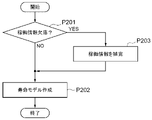
- FIG. 4 is a flow chart showing a processing flow of the life model creating unit 122 of the maintenance management control device 120 of FIG.
- the life model creation unit 122 creates, for example, a life model for each part based on the actual service life of the part for which the replacement factor is determined to be the life factor by the replacement factor determination unit 121. More specifically, the life model creation unit 122 first executes the process P201 for determining whether or not the operation information of the target work machine 10 is missing.
- the life model creation unit 122 executes the process P202 for creating an operation model when it is determined that there is no lack of operation information (NO) of the target work machine 10.
- the life model creation unit 122 uses the operation information of the work machine 10 including the part whose replacement factor is the life factor as an explanatory variable, and aims at the actual service life of the part whose replacement factor is the life factor.
- a lifetime model is created by multiple regression analysis using variables, and the process shown in FIG. 4 is completed.
- the process P201 if the life model creation unit 122 determines that the operation information of the target work machine 10 is missing (YES), the process P203 that supplements the operation information of the work machine 10 is executed.
- the operation information complement unit 125 shown in FIG. 2 creates complementary information for complementing the missing operation information based on the operation model of the work machine 10 when the operation information of the work machine 10 is missing. .. Similar to the failure model creation unit 123 described later, the operation information complement unit 125 creates a group of one or more work machines 10 based on the attribute information of the work machine 10, and the work machine 10 for each created group is created. Complementary information may be created based on the operation model of.
- the life model creation unit 122 executes the process P202 for creating the life model after complementing the missing operation information by using the complement information created by the operation information complement unit 125, and is the process shown in FIG. To finish.
- the life model is, for example, a model showing how a part whose life factor is a failure factor is consumed and replaced by the operation of the work machine 10 during the actual service life of the part.
- the life model creation unit 122 may store the supplemented operation information in the operation information database 113 of the maintenance management DB server 110, and separately from the operation information stored in the operation information database 113, the supplementary information database. It may be stored in 114. This makes it possible to distinguish between the complemented operation information stored in the supplementary information database 114 and the complete operation information stored in the operation information database 113.
- the life model creation unit 122 should use the operation information supplemented in the process P202. Instead, the life model may be created using only the operation information without omission. Further, the life model creation unit 122 may not use the operation information of the work machine 10 whose omission rate exceeds a predetermined value for creating the life model.
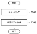
- FIG. 5 is a flow chart showing a processing flow of the failure model creating unit 123 of the maintenance management control device 120 of FIG.
- the failure model creation unit 123 creates a failure model for each part based on the actual service life of each part of each work machine 10 for which the replacement factor is determined to be the failure factor by the replacement factor determination unit 121. It is conceivable that a failure of each component of the work machine 10 will occur with a certain probability depending on, for example, the application and the operation method of the work machine 10.
- the failure model creation unit 123 creates, for example, one or more groups of the work machines 10 including parts whose replacement factors are the failure factors based on the attribute information of the work machines 10, and a plurality of work machines included in each group. A failure model is created for each group based on the operation information of 10.
- the failure model creation unit 123 first executes the grouping process P301.
- the failure model creation unit 123 first refers to the machine database 112, the operation information database 113, and the user information database 115.
- the failure model creation unit 123 has, for example, the attribute information of the work machine 10 that used the part whose replacement factor is the failure factor, the operation information of the work machine 10 during the actual service life of the part, and the work thereof.
- the user information of the machine 10 is acquired.
- the failure model creation unit 123 creates a group of one or more work machines 10 based on the acquired attribute information. More specifically, the failure model creation unit 123 is, for example, the model, model, position information, user identification information, industry, location area, excavation of the work machine 10 that used the part whose replacement factor is the failure factor. The work machines 10 are grouped into one or more groups based on the attribute information such as the object.
- the failure model creation unit 123 executes the failure model creation process P302.
- the failure model creation unit 123 for example, totals the number of parts whose replacement factor is the failure factor in each group, calculates the total number of failures for each part, and operates the work machine 10 of each group. Calculate the total operating time, which is the total time. Further, the failure model creation unit 123 calculates the number of failures per unit time for each component of each group as a failure model by dividing the total number of failures by the total operating time, and ends the process shown in FIG. ..
- the failure model creation unit 123 divides the total number of failures by the total number of operating days, which is the total number of operating days of the work machines 10 of each group, so that the number of failures per day for each part of each group can be calculated as a failure model. It may be calculated as.
- FIG. 6 is a flow chart showing a processing flow of the operation model creating unit 124 of the maintenance management control device 120 of FIG.
- the operation model creation unit 124 is based on, for example, the operation information for each work machine 10 stored in the operation information database 113 of the maintenance management DB server 110 and the market condition information stored in the market condition information database 117 of the maintenance management DB server 110. And create an operation model.
- the operation model creation unit 124 first executes the process P401 for acquiring the operation information for each work machine 10 stored in the operation information database 113 of the maintenance management DB server 110.
- the operation information includes the integrated usage time as described above.
- the operation model creation unit 124 executes the process P402 for acquiring the market condition information for the period corresponding to the operation information of the work machine 10 from the market condition information database 117.
- the market condition information includes at least one of the price and supply / demand of the excavated object of the work machine 10, the fuel price of the work machine 10, and the business conditions index.
- the operation model creation unit 124 performs multiple regression analysis using the transition of the accumulated usage time included in the acquired operation information and the market condition information, creates an operation model for each work machine 10, and is shown in FIG. The processing shown is terminated.
- the operation model creation unit 124 may create an operation model of the work machine 10 for each group created by the above-mentioned grouping process P301 by the failure model creation unit 123. Further, the operation model creation unit 124 may create an operation model by predicting the future operation time based on the past operation information without using the market condition information.
- FIG. 7 is a flow chart showing a processing flow of the replacement time prediction unit 126 of the maintenance management control device 120 of FIG.
- the replacement time prediction unit 126 predicts the replacement time for each part of each work machine 10 based on the above-mentioned life model and failure model. More specifically, the replacement time prediction unit 126 refers to, for example, the replacement information database 116 of the maintenance management DB server 110, and determines whether or not the replacement date is recorded for each part of the work machine 10.
- Process P501 is executed. In this process P501, when the replacement time prediction unit 126 determines that the replacement date is not recorded (NO), for example, the machine database 112 is referred to, and the work machine 10 is used for the part of the work machine 10.
- the process P502 for setting the delivery date to the user to the latest exchange date is executed.
- the replacement time prediction unit 126 determines that the replacement date is recorded (YES)
- the replacement information database 116 is further referred to for the part of the work machine 10.
- the process P503 for determining whether or not a plurality of exchange dates are recorded is executed.
- the exchange time prediction unit 126 determines that the recorded exchange date is one (NO)
- the exchange time prediction unit 126 executes the process P504 for setting the exchange date to the latest exchange date, and the recorded exchange date. If it is determined that there is a plurality (YES), the process P505 for setting the latest exchange date to the latest exchange date is executed.
- the work machine 10 may include, for example, a plurality of the same parts. In this case, it is possible to handle a plurality of the same parts as one part. Even if a plurality of the same parts are not replaced at the same time, they can be treated as individual parts. Further, each work machine 10 may hold a replacement date for each part in the controller 17, for example. When the above process P502, P504, or P505 is completed, the exchange time prediction unit 126 executes the process P506 for predicting the life exchange date.
- the replacement time prediction unit 126 refers to the machine database 112, for example, and refers to the operation model created by the operation model creation unit 124 for each group of the work machines 10 created by the failure model creation unit 123 described above. Refer to. Then, the operation time transition based on the operation model is input to the life model created by the life model creation unit 122, and the life replacement date based on the latest replacement date for each part of each work machine 10 is calculated.
- the actual operating time of the working machine 10 from the latest replacement date for each part of the working machine 10 to the present is input to the life model created by the life model creation unit 122. May be.
- the replacement time forecasting unit 126 sets the life replacement date of the currently used part as the latest replacement date, and executes the above process P506 to replace the life replacement date of the new part after replacing the currently used part. It is also possible to forecast the demand for parts for a longer period of time.
- the replacement time prediction unit 126 executes the process P507 for predicting the failure replacement date.
- the replacement time prediction unit 126 refers to the machine database 112, for example, and refers to the operation model created by the operation model creation unit 124 for each group of the work machines 10 created by the failure model creation unit 123 described above. Refer to. Then, the future operation time transition based on the operation model is input to the failure model created by the failure model creation unit 123, and the failure replacement date based on the latest replacement date for each part of each work machine 10 is calculated. ..
- the replacement time prediction unit 126 inputs, for example, the total of future operating hours based on the operating model for each group into the failure model, and the failure based on the latest replacement date for each part of each work machine 10.
- the exchange date may be calculated.
- the failure replacement date may be calculated based on the application date of the failure model.
- the replacement time prediction unit 126 sets the failure replacement date of the currently used part as the latest replacement date, and executes the above process P507 to replace the failure replacement date of the new part after replacing the currently used part. It is also possible to forecast the demand for parts for a longer period of time.
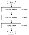
- FIG. 8 is a flow chart showing a processing flow of the exchange number totaling unit 127 of the maintenance management control device 120 of FIG.
- the replacement number totaling unit 127 totals the number of replacements for each part based on the life replacement date and the failure replacement date, which are the replacement times for each part. More specifically, the replacement number totaling unit 127 has a process P601 for acquiring the life replacement date for each part of each work machine 10 calculated by the replacement time prediction unit 126, and a failure for each part of each work machine 10.
- the process P602 for acquiring the exchange date is executed.
- the replacement number totaling unit 127 refers to the user information database 115 and executes the process P603 for totaling the replacement number of each part for each sales agency 40 in charge of each work machine 10.
- the number of replacements of each component can be aggregated in various unit aggregation periods corresponding to the life replacement date and the failure replacement date of each component, for example, daily, weekly, and monthly.
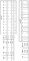
- FIG. 9 is a table showing an example of the aggregation result of the exchange number aggregation unit 127.
- the replacement number totaling unit 127 replaces parts for each month for each model, machine number, distributor name, part name, and part number of the work machine 10. Aggregate the numbers. Further, as shown in the table at the bottom of FIG. 9, the replacement number totaling unit 127 totals the replacement number of the parts for each month for each of the distributor name, the part name, and the part number of the seller 40, for example.
- the manufacturer 30, each distributor 40, and the component supplier 50 of the work machine 10 are, for example, as shown in FIG. 1, the maintenance management DB server 110 or the maintenance management control device of the maintenance management center 20 by the terminals 31, 41, 51. You can access 120 to see the table shown in FIG. This allows the manufacturer 30, the distributor 40, and the component supplier 50 to know in advance the number of future parts ordered.
- FIG. 10 is a flow chart showing a processing flow of the order timing prediction unit 128 of the maintenance management control device 120 of FIG.
- the ordering time prediction unit 128 predicts the ordering time of parts based on the number of replacements for each part and the lead time for each part.
- the order timing prediction unit 128 first refers to the machine database 112 and the user information database 115, and from the manufacturer 30 to each distributor 40 based on the supply route of each part from the manufacturer 30 to each distributor 40.
- the process P701 for calculating the number of shipments of each part of the above for each deadline is executed.
- FIG. 11 is a table for explaining the process 701 by the ordering time prediction unit 128 of FIG.
- the top table of FIG. 11 shows an example of the shipping deadline and the number of parts to be shipped from the regional base of the manufacturer 30 to the seller 40.
- the second table from the top of FIG. 11 shows an example of the shipping deadline and the number of parts shipped from the manufacturer 30 to each of the regional bases of the manufacturer 30 and the distributor 40.
- the third table from the top of FIG. 11 shows an example of the shipping deadline and the number of parts shipped from the manufacturer 30 to the regional bases of the manufacturer 30 and the distributor 40.
- the table at the bottom of FIG. 11 shows an example of the order deadline and the number of parts ordered from the manufacturer 30 to the parts supplier 50.
- the component 1 is supplied from the manufacturer 30 to the distributor a, which is one of the distributors 40, via the regional base, and to the distributor b, which is the other distributor 40. It is supplied directly from the manufacturer 30 without going through a regional base.
- the lead time required for transporting the component 1 from the manufacturer 30 to the regional base is, for example, 3 months
- the lead time required for transporting the component 1 from the regional base to the agency a is, for example, 1 month. do.
- the lead time required for transportation from the manufacturer 30 to the agency b is, for example, two months.
- the lead time required for manufacturing the component 1 at the component supplier 50 and transporting the component 1 from the component supplier 50 to the manufacturer 30 is, for example, 4 months.
- the ordering time prediction unit 128 first, as shown in the table at the bottom of FIG. 9, the agent name and the part name of the seller 40, which are totaled by the exchange number totaling unit 127. , Refer to the number of parts replaced each month for each part number. Then, the order timing prediction unit 128 transfers the number of parts 1 supplied to the distributor a, which is the distributor 40, via the regional base of the manufacturer 30 to the transport of the parts 1 from the regional base to the distributor a. Shift one month before the required lead time. As a result, as shown in the table at the top of FIG. 11, the shipping deadline and the number of shipments from the regional base of the manufacturer 30 to the distributor a, which is the distributor 40, are calculated.
- the ordering time prediction unit 128 sets the shipping deadline and the number of shipments from the regional base of the manufacturer 30 to the distributor a, which is the distributor 40, as shown in the table at the top of FIG. 11, for the parts from the manufacturer 30 to the regional base. Shift to 3 months before the lead time required for transportation of 1. As a result, as shown in the upper row of the second table from the top of FIG. 11, the shipping deadline and the number of shipments from the manufacturer 30 to the regional base of the manufacturer 30 are calculated.
- the order timing prediction unit 128 determines the number of parts to be replaced by the distributor b of the distributor 40 shown in the table below in FIG. 9, in which the component 1 is directly shipped from the manufacturer 30, from the manufacturer 30 to the distributor b. Shift to 2 months before the lead time required to transport the parts 1 up to. As a result, as shown in the lower row of the second table from the top of FIG. 11, the shipping deadline and the number of shipments from the manufacturer 30 to the distributor b, which is the distributor 40, are calculated.
- the ordering time prediction unit 128 totals the number of shipments from the manufacturer 30 to the regional base shown in the second table from the top of FIG. 11 and the number of shipments to the distributor b, which is the distributor 40, for each shipping deadline. do.
- the third table from the top of FIG. 11 it is possible to calculate the shipping deadline and the total number of shipments from the manufacturer 30 to the regional bases of the manufacturer 30 and the seller 40.
- the ordering time prediction unit 128 executes the process P702 for calculating the number of orders for the parts supplier 50 for each deadline.
- the ordering time prediction unit 128 determines the shipping deadline and the total number of shipments from the manufacturer 30 to the regional base and the distributor 40 shown in the third table from the top of FIG. 11, and manufactures the part 1 at the parts supplier 50 and supplies the parts.
- the shift is made four months before the lead time required for the transportation of the component 1 from the original 50 to the manufacturer 30.
- the order deadline and the order quantity of the parts 1 from the manufacturer 30 to the parts supply source 50 can be calculated.
- the process shown in FIG. 10 is completed.
- the manufacturer 30, each distributor 40, and the component supplier 50 of the work machine 10 are, for example, as shown in FIG. 1, the maintenance management DB server 110 or the maintenance management control device of the maintenance management center 20 by the terminals 31, 41, 51. You can access 120 to see the table shown in FIG. This allows the manufacturer 30, the distributor 40, and the component supplier 50 to know in advance the number of future parts ordered.
- FIG. 12 is a table and a graph illustrating processing by the leveling ordering unit 129 of the maintenance management control device 120 of FIG.
- the leveling ordering unit 129 calculates, for example, the number of leveling orders and the leveling order timing for each part that do not exceed the number that can be supplied during the manufacturing period, based on the number of replacements and the number of supplies that can be supplied for each part.
- the number of parts ordered from the parts supplier 50 is equalized so as not to exceed the number that can be supplied during the manufacturing period of the parts by the parts supplier 50, and the number required by the deadline for shipping the parts to the distributor 40 or the like. It is necessary to ensure that the parts of the above are delivered from the parts supplier 50 to the manufacturer 30. For example, it is assumed that the number of parts 1 of the parts supply source 50 that can be supplied during the manufacturing period is 10.
- the leveling ordering unit 129 for example, as shown in the table above FIG. 12, is required for each ordering deadline based on the required number of parts 1 ordered from the manufacturer 30 to the parts supplier 50 and the ordering deadline. Calculate the integrated value of the ordered quantity.
- the leveling ordering unit 129 calculates, for example, as shown in the table above FIG. 12, the number of leveling orders of 10 or less that does not exceed the supplyable number of the parts 1 of the parts supply source 50 during the manufacturing period. .. At this time, the leveling ordering unit 129 calculates, for example, the number of leveling orders so that the integrated value of the leveling ordering unit 129 for each ordering deadline is equal to or greater than the integrated value of the required order quantity at all the ordering deadlines. do. As a result, the ordering of the component 1 exceeding the supply capacity of the component supply source 50 is prevented, and the component 1 can be stably supplied. Further, the leveling ordering unit 129 may consider the number of parts 1 in stock at the parts supply source 50.
- the work machine maintenance management system 100 of the present embodiment has a maintenance management DB server 110 that stores maintenance management information of a plurality of work machines 10, and each work machine 10 based on the maintenance management information.
- a maintenance management control device 120 for predicting replacement time for each part is provided.
- the above-mentioned maintenance management information stored in the maintenance management DB server 110 includes an actual service life period from the start of use to replacement of each part of each work machine 10.
- the maintenance management control device 120 is replaced by a replacement factor determination unit 121 that determines a replacement factor for each component as a life factor or a failure factor based on the actual service life of each component of the plurality of work machines 10, and a replacement factor determination unit 121.
- a life model creation unit 122 that creates a life model of a part whose factor is determined to be a life factor
- a failure model creation unit 123 that creates a failure model of a part whose replacement factor is determined to be a failure factor by the replacement factor determination unit 121.
- a replacement time prediction unit 126 that predicts a replacement time for each part of each work machine 10 based on these life models and failure models.
- the maintenance management system 100 of the work machine of the present embodiment can predict the replacement time of the parts of the work machine 10 earlier. More specifically, maintenance management information including the actual service life of each part of each work machine 10 is stored in the maintenance management DB server 110, and the replacement factor determination unit 121 of the maintenance management control device 120 based on the actual service life. , The replacement factor can be determined for each part of the work machine 10. Further, based on the replacement factor, the maintenance management control device 120 can create a life model for each part by the life model creating unit 122, and can create a failure model for each part by the failure model creating unit 123.
- the maintenance management control device 120 predicts the replacement time for each part of each work machine 10 in consideration of both the life and the failure by the replacement time prediction unit 126 based on the created life model and the failure model. be able to. Therefore, according to the present embodiment, it is possible to provide the maintenance management system 100 for the work machine, which can predict the replacement time of the parts of the work machine 10 at an earlier stage.
- the above maintenance management information stored in the maintenance management DB server 110 includes, for example, a lead time from ordering to delivery for each part of each work machine 10.
- the maintenance management control device 120 orders the parts based on the replacement number totaling unit 127 that totals the replacement number of each part based on the replacement time of each part, and the replacement number of each part and the lead time of each part. It has an ordering time prediction unit 128 for predicting the time.
- the maintenance management system 100 of the present embodiment can predict the ordering time in consideration of the lead time for each part, and can order and deliver the parts earlier. Therefore, at the site where the work machine 10 is used, the parts of the work machine 10 can be delivered before the parts are replaced, and the operation stop period of the work machine 10 can be minimized.
- the above maintenance management information stored in the maintenance management DB server 110 includes the number of parts that can be supplied during the manufacturing period for each part.
- the maintenance management control device 120 calculates the leveling order number and the leveling order timing that do not exceed the supplyable number in the manufacturing period for each part based on the replacement number and the supplyable number for each part. Has. With such a configuration, the maintenance management system 100 of the present embodiment can prevent the ordering of parts exceeding the supply capacity of the parts supply source 50, and can stably supply the parts.
- the above maintenance management information stored in the maintenance management DB server 110 includes the operation information of each work machine 10.
- the life model creation unit 122 uses multiple regression analysis using the operation information of the work machine 10 including the part whose replacement factor is the life factor as an explanatory variable and the actual service life of the part whose replacement factor is the life factor as the objective variable. To create a life model. With such a configuration, the maintenance management system 100 of the present embodiment can more accurately predict the life of each part of each work machine 10 based on the operation information of each work machine 10. ..
- the above maintenance management information stored in the maintenance management DB server 110 includes attribute information and operation information of each work machine 10.
- the failure model creation unit 123 creates one or more groups of the work machines 10 including parts whose replacement factors are the failure factors based on the attribute information of the work machines 10, and a plurality of work machines included in each group. A failure model is created for each group based on the operation information of 10. With such a configuration, for example, a failure model can be created for each group having similar operation information of the work machine 10, and a failure for each part of each work machine 10 can be predicted more accurately. Become.
- the above maintenance management information stored in the maintenance management DB server 110 includes market condition information related to each work machine 10.
- the maintenance management control device 120 creates an operation model creation unit 124 that creates an operation model based on the operation information and market condition information for each work machine 10, and creates supplementary information based on the operation model when the operation information is missing. It has an operation information complementing unit 125 and the operation information complementing unit 125. With such a configuration, it is possible to input the future operation time transition of the work machine 10 based on the operation model into the failure model and predict the failure of the parts more accurately.
- the operation model creation unit 124 creates an operation model for each group. Further, the operation information complement unit 125 creates supplementary information based on the operation model for each group when the operation information is missing. With such a configuration, the total future operating time based on the operating model for each group can be input to the failure model to more accurately predict the failure of the component.
Landscapes
- Engineering & Computer Science (AREA)
- Business, Economics & Management (AREA)
- Human Resources & Organizations (AREA)
- General Physics & Mathematics (AREA)
- Physics & Mathematics (AREA)
- Strategic Management (AREA)
- Economics (AREA)
- Entrepreneurship & Innovation (AREA)
- Quality & Reliability (AREA)
- Tourism & Hospitality (AREA)
- Automation & Control Theory (AREA)
- Marketing (AREA)
- Theoretical Computer Science (AREA)
- General Business, Economics & Management (AREA)
- Operations Research (AREA)
- General Engineering & Computer Science (AREA)
- Game Theory and Decision Science (AREA)
- Educational Administration (AREA)
- Manufacturing & Machinery (AREA)
- Development Economics (AREA)
- Health & Medical Sciences (AREA)
- General Health & Medical Sciences (AREA)
- Primary Health Care (AREA)
- Management, Administration, Business Operations System, And Electronic Commerce (AREA)
- General Factory Administration (AREA)
Abstract
Priority Applications (5)
| Application Number | Priority Date | Filing Date | Title |
|---|---|---|---|
| EP21880138.9A EP4231211A4 (fr) | 2020-10-13 | 2021-10-13 | Système de gestion de maintenance de machine de travail |
| CN202180017315.5A CN115176257B (zh) | 2020-10-13 | 2021-10-13 | 作业机械的维护管理系统 |
| US17/909,031 US12276976B2 (en) | 2020-10-13 | 2021-10-13 | Work machine maintenance management system |
| JP2022557031A JP7304499B2 (ja) | 2020-10-13 | 2021-10-13 | 作業機械の保守管理システム |
| KR1020227029258A KR102778771B1 (ko) | 2020-10-13 | 2021-10-13 | 작업 기계의 보수 관리 시스템 |
Applications Claiming Priority (2)
| Application Number | Priority Date | Filing Date | Title |
|---|---|---|---|
| JP2020-172283 | 2020-10-13 | ||
| JP2020172283 | 2020-10-13 |
Publications (1)
| Publication Number | Publication Date |
|---|---|
| WO2022080400A1 true WO2022080400A1 (fr) | 2022-04-21 |
Family
ID=81208067
Family Applications (1)
| Application Number | Title | Priority Date | Filing Date |
|---|---|---|---|
| PCT/JP2021/037846 Ceased WO2022080400A1 (fr) | 2020-10-13 | 2021-10-13 | Système de gestion de maintenance de machine de travail |
Country Status (6)
| Country | Link |
|---|---|
| US (1) | US12276976B2 (fr) |
| EP (1) | EP4231211A4 (fr) |
| JP (1) | JP7304499B2 (fr) |
| KR (1) | KR102778771B1 (fr) |
| CN (1) | CN115176257B (fr) |
| WO (1) | WO2022080400A1 (fr) |
Cited By (3)
| Publication number | Priority date | Publication date | Assignee | Title |
|---|---|---|---|---|
| JP2023166082A (ja) * | 2022-05-09 | 2023-11-21 | 三菱重工業株式会社 | 中古車両情報処理装置、中古車両情報処理方法およびプログラム |
| JP7398019B1 (ja) | 2023-03-28 | 2023-12-13 | 株式会社日立パワーソリューションズ | 保守支援装置及び保守支援方法 |
| CN119515364A (zh) * | 2025-01-22 | 2025-02-25 | 杭州智诚惠通科技有限公司 | 一种基于当量轴次的道路智能维护方法、系统和介质 |
Families Citing this family (5)
| Publication number | Priority date | Publication date | Assignee | Title |
|---|---|---|---|---|
| US12554255B2 (en) * | 2021-03-31 | 2026-02-17 | Hitachi Construction Machinery Co., Ltd. | Component service life prediction system and maintenance assistance system |
| JP7817384B2 (ja) * | 2022-05-13 | 2026-02-18 | ファナック株式会社 | 産業機械の保守管理装置および生産システム |
| CN116258481B (zh) * | 2023-05-15 | 2023-08-15 | 青建集团股份公司 | 一种建筑工程智慧建造的管控方法及系统 |
| CN118037278A (zh) * | 2024-04-12 | 2024-05-14 | 汶上县华诚机械有限公司 | 基于数据分析的工程机械智能运维管理系统 |
| CN120198107B (zh) * | 2025-05-27 | 2025-08-22 | 中铁建设集团有限公司 | 基于深度强化学习的设备预测性维护方法 |
Citations (4)
| Publication number | Priority date | Publication date | Assignee | Title |
|---|---|---|---|---|
| JP2001356808A (ja) | 2000-06-16 | 2001-12-26 | Ntn Corp | 機械部品の監視・診断・販売システム |
| JP2009068259A (ja) * | 2007-09-13 | 2009-04-02 | Caterpillar Japan Ltd | 作業機械寿命推定法 |
| JP2014174684A (ja) * | 2013-03-07 | 2014-09-22 | Ihi Corp | メンテナンス支援システム及び方法 |
| JP2017174308A (ja) * | 2016-03-25 | 2017-09-28 | 日立建機株式会社 | 作業機械の部品交換時期算出システム |
Family Cites Families (16)
| Publication number | Priority date | Publication date | Assignee | Title |
|---|---|---|---|---|
| JPS5718457B2 (fr) * | 1973-06-27 | 1982-04-16 | ||
| DE60136773D1 (de) | 2000-06-16 | 2009-01-15 | Ntn Toyo Bearing Co Ltd | Überwachungs-, Diagnose- und Verkaufssystem für Maschinenkomponenten |
| EP1172717A3 (fr) * | 2000-07-11 | 2003-08-13 | Komatsu Ltd. | Système, méthode, logiciel et support d'enregistrement pour la gestion de machines |
| JP4416306B2 (ja) * | 2000-11-06 | 2010-02-17 | 株式会社小松製作所 | メンテナンスシステムおよびメンテナンス方法 |
| KR100696730B1 (ko) * | 2002-06-12 | 2007-03-20 | 히다치 겡키 가부시키 가이샤 | 건설기계의 정보제공시스템 및 건설기계의 정보제공방법 |
| JP4717579B2 (ja) * | 2005-09-30 | 2011-07-06 | 株式会社小松製作所 | 作業機械のメンテナンス作業管理システム |
| JP5718457B2 (ja) * | 2011-05-13 | 2015-05-13 | 株式会社日立製作所 | 保守部品寿命予測システムおよび保守部品寿命予測方法 |
| US20130041783A1 (en) * | 2011-08-11 | 2013-02-14 | General Electric Company | System and method for dynamic spare part management |
| WO2013186880A1 (fr) * | 2012-06-13 | 2013-12-19 | 株式会社日立製作所 | Procédé et système pour gérer l'intervalle de temps pour remplacer des pièces de service |
| JP6298797B2 (ja) * | 2015-06-18 | 2018-03-20 | 日立建機株式会社 | 建設機械の交換品管理システム |
| JP6612114B2 (ja) * | 2015-11-30 | 2019-11-27 | 株式会社日立製作所 | 部品発注制御装置および部品発注制御方法 |
| JP6285403B2 (ja) * | 2015-11-30 | 2018-02-28 | ファナック株式会社 | 製造機械の故障を予測するセル制御装置および生産システム |
| JP6916754B2 (ja) * | 2018-02-28 | 2021-08-11 | 三菱パワー株式会社 | プラント運転支援装置、および、プラント運転支援方法 |
| JP7018788B2 (ja) * | 2018-03-05 | 2022-02-14 | 鹿島建設株式会社 | 管理システム、管理方法及び管理プログラム |
| KR102168218B1 (ko) * | 2018-10-31 | 2020-10-20 | 한국철도기술연구원 | 열차 고장 예측 장치 및 방법 |
| JP6764546B1 (ja) * | 2020-04-27 | 2020-09-30 | Eyアドバイザリー・アンド・コンサルティング株式会社 | 情報処理システム及び情報処理方法 |
-
2021
- 2021-10-13 WO PCT/JP2021/037846 patent/WO2022080400A1/fr not_active Ceased
- 2021-10-13 JP JP2022557031A patent/JP7304499B2/ja active Active
- 2021-10-13 KR KR1020227029258A patent/KR102778771B1/ko active Active
- 2021-10-13 CN CN202180017315.5A patent/CN115176257B/zh active Active
- 2021-10-13 US US17/909,031 patent/US12276976B2/en active Active
- 2021-10-13 EP EP21880138.9A patent/EP4231211A4/fr active Pending
Patent Citations (4)
| Publication number | Priority date | Publication date | Assignee | Title |
|---|---|---|---|---|
| JP2001356808A (ja) | 2000-06-16 | 2001-12-26 | Ntn Corp | 機械部品の監視・診断・販売システム |
| JP2009068259A (ja) * | 2007-09-13 | 2009-04-02 | Caterpillar Japan Ltd | 作業機械寿命推定法 |
| JP2014174684A (ja) * | 2013-03-07 | 2014-09-22 | Ihi Corp | メンテナンス支援システム及び方法 |
| JP2017174308A (ja) * | 2016-03-25 | 2017-09-28 | 日立建機株式会社 | 作業機械の部品交換時期算出システム |
Non-Patent Citations (1)
| Title |
|---|
| See also references of EP4231211A4 |
Cited By (5)
| Publication number | Priority date | Publication date | Assignee | Title |
|---|---|---|---|---|
| JP2023166082A (ja) * | 2022-05-09 | 2023-11-21 | 三菱重工業株式会社 | 中古車両情報処理装置、中古車両情報処理方法およびプログラム |
| JP7837209B2 (ja) | 2022-05-09 | 2026-03-30 | 三菱重工業株式会社 | 中古車両情報処理装置、中古車両情報処理方法およびプログラム |
| JP7398019B1 (ja) | 2023-03-28 | 2023-12-13 | 株式会社日立パワーソリューションズ | 保守支援装置及び保守支援方法 |
| JP2024140989A (ja) * | 2023-03-28 | 2024-10-10 | 株式会社日立パワーソリューションズ | 保守支援装置及び保守支援方法 |
| CN119515364A (zh) * | 2025-01-22 | 2025-02-25 | 杭州智诚惠通科技有限公司 | 一种基于当量轴次的道路智能维护方法、系统和介质 |
Also Published As
| Publication number | Publication date |
|---|---|
| CN115176257B (zh) | 2026-02-24 |
| EP4231211A4 (fr) | 2024-11-13 |
| US12276976B2 (en) | 2025-04-15 |
| KR102778771B1 (ko) | 2025-03-12 |
| JPWO2022080400A1 (fr) | 2022-04-21 |
| US20230092796A1 (en) | 2023-03-23 |
| JP7304499B2 (ja) | 2023-07-06 |
| CN115176257A (zh) | 2022-10-11 |
| EP4231211A1 (fr) | 2023-08-23 |
| KR20220132587A (ko) | 2022-09-30 |
Similar Documents
| Publication | Publication Date | Title |
|---|---|---|
| WO2022080400A1 (fr) | Système de gestion de maintenance de machine de travail | |
| US9015059B2 (en) | Wireless system for automatic ordering of maintenance parts for equipment | |
| US7496475B2 (en) | Maintenance management of a machine | |
| WO2018051108A1 (fr) | Système de commande de supervision automatisé | |
| US20160078695A1 (en) | Method and system for managing a fleet of remote assets and/or ascertaining a repair for an asset | |
| US11915187B2 (en) | Method and system for tracking inventory including inventory level reconciliation across inventory tracking system | |
| WO2011054005A2 (fr) | Système de maintenance corrective et prédictive automatisé | |
| WO2005043481A1 (fr) | Systeme de gestion d'une machine de travail | |
| JPWO2014136956A1 (ja) | 作業機械の管理サーバ及び作業機械の管理方法 | |
| CN102955876A (zh) | 动态备件管理的系统和方法 | |
| US10915069B2 (en) | Monitoring system for monitoring usage of uniquely identifiable machine components | |
| US20210295345A1 (en) | System and method to provide warranty for a utility equipment | |
| US20060273918A1 (en) | System for providing multiple maintenance profiles using wireless communications | |
| CN110914842A (zh) | 用于机器的自动维护的方法和系统 | |
| JP6908201B1 (ja) | データ処理装置、アセット管理装置、及び保守部品管理装置 | |
| US11574508B2 (en) | Predictive, preventative and conditional maintenance method and system for commercial vehicle fleets | |
| Selvakumar et al. | Smart asset management: Tracking and optimizing assets with IoT sensors | |
| CN101273316A (zh) | 资产管理系统 | |
| WO2011067810A1 (fr) | Procédé de gestion des stocks de composants, procédé de prévision de demande en composants, programme de gestion des stocks de composants, dispositif de traitement d'informations et système de gestion des stocks de composants | |
| WO2002089029A2 (fr) | Systeme de commande de pieces detachees et d'inspection a reception | |
| EP4455967A1 (fr) | Procédé mis en uvre par ordinateur pour optimiser un programme de maintenance pour maintenir un système technique ou au moins un composant technique du système technique | |
| Bowman et al. | How the Internet of Things will improve reliability tracking | |
| WO2025142082A1 (fr) | Procédé, système et programme de gestion de composants | |
| Tau et al. | Fly Ash Packaging Plant Downtime Assessment to Maintain Product Supply: A Case Study | |
| BG4090U1 (bg) | Система за управление и автоматизиране на процесите по планиране, контрол и управление на транспортната дейност |
Legal Events
| Date | Code | Title | Description |
|---|---|---|---|
| 121 | Ep: the epo has been informed by wipo that ep was designated in this application |
Ref document number: 21880138 Country of ref document: EP Kind code of ref document: A1 |
|
| ENP | Entry into the national phase |
Ref document number: 2022557031 Country of ref document: JP Kind code of ref document: A |
|
| ENP | Entry into the national phase |
Ref document number: 20227029258 Country of ref document: KR Kind code of ref document: A |
|
| NENP | Non-entry into the national phase |
Ref country code: DE |
|
| ENP | Entry into the national phase |
Ref document number: 2021880138 Country of ref document: EP Effective date: 20230515 |
|
| WWG | Wipo information: grant in national office |
Ref document number: 17909031 Country of ref document: US |