WO2022085331A1 - Dispositif de commande de direction, procédé de commande de direction et programme de commande de direction - Google Patents
Dispositif de commande de direction, procédé de commande de direction et programme de commande de direction Download PDFInfo
- Publication number
- WO2022085331A1 WO2022085331A1 PCT/JP2021/033316 JP2021033316W WO2022085331A1 WO 2022085331 A1 WO2022085331 A1 WO 2022085331A1 JP 2021033316 W JP2021033316 W JP 2021033316W WO 2022085331 A1 WO2022085331 A1 WO 2022085331A1
- Authority
- WO
- WIPO (PCT)
- Prior art keywords
- steering
- actuator
- control
- steering control
- control unit
- Prior art date
- Legal status (The legal status is an assumption and is not a legal conclusion. Google has not performed a legal analysis and makes no representation as to the accuracy of the status listed.)
- Ceased
Links
Images





Classifications
-
- B—PERFORMING OPERATIONS; TRANSPORTING
- B62—LAND VEHICLES FOR TRAVELLING OTHERWISE THAN ON RAILS
- B62D—MOTOR VEHICLES; TRAILERS
- B62D5/00—Power-assisted or power-driven steering
- B62D5/04—Power-assisted or power-driven steering electrical, e.g. using an electric servo-motor connected to, or forming part of, the steering gear
- B62D5/0457—Power-assisted or power-driven steering electrical, e.g. using an electric servo-motor connected to, or forming part of, the steering gear characterised by control features of the drive means as such
- B62D5/046—Controlling the motor
-
- B—PERFORMING OPERATIONS; TRANSPORTING
- B62—LAND VEHICLES FOR TRAVELLING OTHERWISE THAN ON RAILS
- B62D—MOTOR VEHICLES; TRAILERS
- B62D5/00—Power-assisted or power-driven steering
- B62D5/04—Power-assisted or power-driven steering electrical, e.g. using an electric servo-motor connected to, or forming part of, the steering gear
- B62D5/0457—Power-assisted or power-driven steering electrical, e.g. using an electric servo-motor connected to, or forming part of, the steering gear characterised by control features of the drive means as such
- B62D5/0481—Power-assisted or power-driven steering electrical, e.g. using an electric servo-motor connected to, or forming part of, the steering gear characterised by control features of the drive means as such monitoring the steering system, e.g. failures
-
- B—PERFORMING OPERATIONS; TRANSPORTING
- B62—LAND VEHICLES FOR TRAVELLING OTHERWISE THAN ON RAILS
- B62D—MOTOR VEHICLES; TRAILERS
- B62D15/00—Steering not otherwise provided for
- B62D15/02—Steering position indicators ; Steering position determination; Steering aids
- B62D15/0205—Mechanical indicators, e.g. in or near steering wheel
-
- B—PERFORMING OPERATIONS; TRANSPORTING
- B62—LAND VEHICLES FOR TRAVELLING OTHERWISE THAN ON RAILS
- B62D—MOTOR VEHICLES; TRAILERS
- B62D15/00—Steering not otherwise provided for
- B62D15/02—Steering position indicators ; Steering position determination; Steering aids
- B62D15/025—Active steering aids, e.g. helping the driver by actively influencing the steering system after environment evaluation
-
- B—PERFORMING OPERATIONS; TRANSPORTING
- B62—LAND VEHICLES FOR TRAVELLING OTHERWISE THAN ON RAILS
- B62D—MOTOR VEHICLES; TRAILERS
- B62D6/00—Arrangements for automatically controlling steering depending on driving conditions sensed and responded to, e.g. control circuits
- B62D6/008—Control of feed-back to the steering input member, e.g. simulating road feel in steer-by-wire applications
Definitions
- This disclosure relates to steering control technology in vehicles.
- the technique of electrically controlling the steering angle of the steering member of a vehicle and the steering angle of a steering tire has become widespread.
- the steering angle of the steering tire is controlled by the steering torque output to the steering tire via the electric actuator.
- the locking device regulates the rotation of the steering tire in the locked state.
- the lock device is configured to be in the locked state before the power is turned off in response to the vehicle stop command and to be released in the locked state in response to the vehicle start command.
- the lock device does not operate in response to the vehicle stop command, the life can be secured.
- the torque output to the steering tire via the electric actuator suddenly disappears in response to the energization cut to the electric actuator.
- the steering tire is rapidly restored so as to eliminate the twist, the steering tire and the vehicle body supporting the steering tire vibrate in the vehicle.
- the locking device is not activated, the steering member to which the vibration of the steering tire propagates also vibrates.
- An object of the present disclosure is to provide a steering control device that suppresses the generation of vibration accompanying a vehicle stop command. Another object of the present disclosure is to provide a steering control method for suppressing the generation of vibration accompanying a stop command of a vehicle. Yet another object of the present disclosure is to provide a steering control program that suppresses the generation of vibration accompanying a vehicle stop command.
- the first aspect of the present disclosure is a steering control device that links the movement of a steering member by a steering actuator and the movement of a steering tire by a steering actuator by control in a vehicle, and is a steering output from the steering actuator.
- the steering control unit that controls the output torque and controls the actual steering angle of the steering member via the steering actuator, and the steering output torque output from the steering actuator are controlled, and the steering tire is controlled via the steering actuator.
- It is equipped with a steering control unit that controls the actual steering angle, and the steering control unit is in interlocking control in which the steering control unit interlocks and controls the actual steering angle with respect to the actual steering angle in response to a vehicle stop command.
- the steering output torque is gradually reduced, and the steering control unit and the steering control unit cut the energization to the steering actuator and the steering actuator, respectively, after the steering output torque is gradually reduced and controlled by the steering control unit.
- the second aspect of the present disclosure is a steering control method in which the movement of the steering member by the steering actuator and the movement of the steering tire by the steering actuator are linked by control in the vehicle, and the steering output from the steering actuator is controlled.
- the steering control process that controls the output torque and controls the actual steering angle of the steering member via the steering actuator, and the steering output torque that is output from the steering actuator is controlled, and the steering tire is controlled via the steering actuator.
- the steering control process includes a steering control process for controlling the actual steering angle, and the steering control process is an interlocking control process in which the actual steering angle is interlocked with respect to the actual steering angle by the steering control process in response to a vehicle stop command.
- the steering output torque is gradually reduced and controlled, and the steering control process and the steering control process cut the energization to the steering actuator and the steering actuator, respectively, after the steering output torque is gradually reduced and controlled by the steering control process.
- the third aspect of the present disclosure is a steering control program including a command to be executed by a processor in order to link the movement of the steering member by the steering actuator and the movement of the steering tire by the steering actuator by control in the vehicle.
- the command is a steering control process that controls the steering output torque output from the steering actuator and controls the actual steering angle of the steering member via the steering actuator, and the steering output torque output from the steering actuator.
- the steering control process includes a steering control step of controlling and controlling the actual steering angle of the steering tire via the steering actuator, and the steering control process adjusts the actual steering angle by the steering control process in accordance with the vehicle stop command.
- the steering output torque is gradually reduced, and the steering control process and the steering control process are steered after the steering output torque is gradually decreased and controlled by the steering control process.
- the energization to the actuator and the steering actuator is cut off.
- the steering output torque from the steering actuator is gradually reduced and controlled during the interlocking control in which the actual steering angle is interlocked with respect to the actual steering angle in response to the vehicle stop command.
- the energization to the steering actuator and the steering actuator is cut off.
- the twist of the steering tire can be gradually eliminated according to the gradual decrease control of the steering output torque, so that the steering tire is suddenly restored. It becomes difficult. Therefore, it is possible to suppress the generation of vibration of the steering tire and the vehicle body supporting the steering tire due to the restoration of the steering tire in accordance with the stop command.
- the gradual reduction control of the steering output torque is realized during the interlocking control between the actual steering angle and the actual steering angle, the vibration of the steering member interlocking with the steering tire is also suppressed in accordance with the stop command. be able to.
- the steering control device 1 As shown in FIG. 1, the steering control device 1 according to the first embodiment is mounted on the vehicle 2.
- the vehicle 2 is capable of constantly or temporarily automatically traveling in the automatic driving mode.
- the automated driving mode may be realized by autonomous driving control in which the system at the time of operation performs all driving tasks, such as conditional driving automation, advanced driving automation, or full luck automation.
- the automated driving mode may be implemented in advanced driving assistance control in which the occupant performs some or all driving tasks, such as driving assistance or partial driving automation.
- the automatic driving mode may be realized by combining or switching between the autonomous driving control and the advanced driving support control.
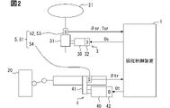
- the steering actuator 3 includes a steering motor 30, a steering reducer 31, and a steering driver 32.
- the steering actuator 3 is mechanically linked to the steering wheel 21 of the vehicle 2.
- the steering actuator 3 controls the current applied to the electric steering motor 30 according to the output command Os from the steering control device 1 by the steering driver 32.
- the steering actuator 3 generates steering torque by the steering motor 30 to which an electric current is applied.
- the steering actuator 3 amplifies the steering torque generated by the steering motor 30 by a steering reducer 31 such as a planetary gear, and then outputs the torque.
- the output steering torque is transmitted as a reaction force from the steering actuator 3 to the steering wheel 21, so that the actual steering angle ⁇ sr (see FIG. 1) of the steering wheel 21 can be changed.
- the actual steering angle ⁇ sr and the target steering angle ⁇ st thereof are given a positive (plus) value on the right side and a negative (minus) value on the left side with respect to the front-rear direction of the vehicle 2, respectively. Similarly, positive and negative values are given to the output command Os to the steering actuator 3.
- the steering actuator 4 includes a steering motor 40, a steering reducer 41, and a steering driver 42.
- the steering actuator 4 is mechanically linked to the steering tire 20 of the vehicle 2.
- the steering actuator 4 constitutes a steer-by-wire system that mechanically shuts off and electrically cooperates with the steering wheel 21 and the steering actuator 3.
- the steering actuator 4 controls the current applied to the electric steering motor 40 according to the output command Ot from the steering control device 1 by the steering driver 42.
- the steering actuator 4 generates steering torque by the steering motor 40 to which an electric current is applied.
- the steering actuator 4 amplifies the steering torque generated by the steering motor 40 by a steering speed reducer 41 such as a rack gear, and then outputs the torque.
- the output steering torque is transmitted as a driving force from the steering actuator 4 to the steering tire 20, so that the actual steering angle ⁇ tr (see FIG. 1) of the steering tire 20 changes.
- the actual steering angle ⁇ tr and the target steering angle ⁇ tt thereof are given positive (plus) values on the right side and negative (minus) values on the left side of the vehicle 2 in the front-rear direction. Be done. Similarly, positive and negative values are given to the output command Ot to the steering actuator 4.
- the sensor system 5 includes an outside world sensor 50 and an inside world sensor 51.
- the outside world sensor 50 acquires information on the outside world, which is the surrounding environment of the vehicle 2.
- the outside world sensor 50 may acquire outside world information by detecting an object existing in the outside world of the vehicle 2.
- the object detection type external sensor 50 is, for example, at least one of a camera, a LiDAR (Light Detection and Ringing / Laser Imaging Detection and Ringing), a radar, a sonar, and the like.
- the outside world sensor 50 may acquire outside world information by receiving a specific signal from a GNSS (Global Navigation Satellite System) artificial satellite or an ITS (Intelligent Transport Systems) roadside machine existing in the outside world of the vehicle 2.
- the signal reception type external sensor 50 is at least one of, for example, a GNSS receiver, a telematics receiver, and the like.
- the inner world sensor 51 acquires information on the inner world, which is the internal environment of the vehicle 2.
- the inner world sensor 51 may acquire the inner world information by detecting a specific kinetic physical quantity in the inner world of the vehicle 2.
- the physical quantity detection type internal sensor 51 is, for example, at least a sensor 52 among a steering torque sensor 52, a steering angle sensor 53, a steering angle sensor 54, a speed sensor, an acceleration sensor, an inertial sensor, a yaw rate sensor, a start sensor 55, and the like. , 53, 54, 55 and more.
- the steering torque sensor 52 acquires the actual steering torque Tsr given to the steering wheel 21.
- the steering angle sensor 53 acquires the actual steering angle ⁇ sr of the steering wheel 21.
- the steering angle sensor 54 acquires the actual steering angle ⁇ tr of the steering tire 20.
- the start sensor 55 outputs a start command for the vehicle 2 in response to the occupant of the vehicle 2 turning on the start switch.
- the start sensor 55 outputs a stop command Oe of the vehicle 2 in response to the occupant of the vehicle 2 turning off the start switch.
- the start sensor 55 outputs an idling stop command and a restart command when the vehicle 2 is idling stop.
- the steering control device 1 is connected to the steering actuator 3, the steering actuator 4, and the sensor system 5 via at least one of a LAN (Local Area Network), a wire harness, an internal bus, and the like.
- the steering control device 1 includes at least one dedicated computer.
- the dedicated computer constituting the steering control device 1 may be an operation control ECU (Electronic Control Unit) that realizes operation control including an automatic operation mode.
- the dedicated computer constituting the steering control device 1 may be at least one of a steering ECU that controls the steering actuator 3 and a steering ECU that controls the steering actuator 4.
- the dedicated computer constituting the steering control device 1 may be a locator ECU that estimates the state quantity of the vehicle 2 including the position of the vehicle 2.
- the dedicated computer constituting the steering control device 1 may be a navigation ECU for navigating the driving of the vehicle 2.
- the dedicated computer constituting the steering control device 1 may be an HCU (HMI (Human Machine Interface) Control Unit) that controls the information presentation of the vehicle 2.
- HCU Human Machine Interface
- the steering control device 1 includes at least one memory 10 and one processor 12 by including such a dedicated computer.
- the memory 10 non-transitory tangible stores at least one type of non-transitory substantive storage medium (non-transitory tangible), for example, a semiconductor memory, a magnetic medium, an optical medium, or the like, which stores a computer-readable program and data non-temporarily. storage medium).
- the processor 12 includes, for example, at least one of a CPU (Central Processing Unit), a GPU (Graphics Processing Unit), a RISC (Reduced Instruction Set Computer) -CPU, and the like as a core.
- a CPU Central Processing Unit
- GPU Graphics Processing Unit
- RISC Reduced Instruction Set Computer
- the processor 12 executes a plurality of instructions included in the steering control program stored in the memory 10.
- the steering control device 1 constructs a plurality of functional units, which are functional blocks for interlocking steering and steering by control in the vehicle 2, as shown in FIG.
- the steering control program stored in the memory 10 causes the processor 12 to execute a plurality of instructions in order to interlock the steering and steering in the vehicle 2 by control, so that a plurality of functional units can be used. Will be built.
- Such a plurality of functional units include a track generation unit 100, a steering control unit 110, and a steering control unit 120.
- the orbit generation unit 100 generates a planned orbit Tz based on the input information from the sensor system 5 or the corresponding physical information.
- the planned track Tz means a traveling track that defines a time-series change in the state quantity (hereinafter referred to as self-state quantity) in the vehicle 2.
- the self-state quantity is a physical quantity including at least the position of the vehicle 2. Such a self-state quantity may include, for example, at least one of traveling speed, acceleration, yaw angle, and the like in addition to the position.
- the trajectory generation unit 100 generates a control command required for the steering control unit 110 and the steering control unit 120. Specifically, the track generation unit 100 generates an automatic driving command Oa for executing the automatic driving mode in the driving control of the vehicle 2. The track generation unit 100 generates a stop command Oe for executing a stop control mode for stopping the vehicle 2 during the automatic driving mode in the operation control of the vehicle 2.
- the stop command Oe in the automatic operation mode is at least one of a complete stop command for the vehicle 2, an idling stop command for the vehicle 2, a power stop command for the actuators 3 and 4, and the like.
- the timing at which the track generation unit 100 outputs the stop command Oe may be any of immediately before the scheduled time when the track generation unit 100 determines to stop the vehicle 2, the scheduled time, and immediately after the scheduled time.
- the stop command Oe for executing the stop control mode is output from the start sensor 55 during the manual operation mode.
- the stop command Oe in the manual operation mode is at least one of the complete stop command of the vehicle 2 by the off operation of the start switch, the idling stop command of the vehicle 2, and the like.
- the steering control unit 110 controls the steering output torque Tso output from the steering actuator 3, the control of the actual steering angle ⁇ sr via the steering actuator 3, and the control of the actual steering torque Tsr via the steering actuator 3. Selectively execute. Therefore, the steering control unit 110 has, as sub-functional units, a target steering angle selection unit 111, a target steering torque control unit 112, a steering angle follow-up control unit 113, a torque follow-up control unit 114, a steering current selection unit 115, and steering gradual reduction control. It has a part 116.
- the stop command Oe and the scheduled trajectory Tz are input from the trajectory generation unit 100 to the target steering angle selection unit 111.
- a stop command Oe is input from the start sensor 55 to the target steering angle selection unit 111.
- the actual steering angle ⁇ tr is input from the steering angle sensor 54 to the target steering angle selection unit 111.
- the target steering angle selection unit 111 selects the target steering angle ⁇ st, which is the control target of the actual steering angle ⁇ sr, based on these inputs.
- the target steering angle selection unit 111 selects the target steering angle ⁇ st acquired so as to follow the planned trajectory Tz.
- the target steering angle selection unit 111 executes interlocking control in which the actual steering angle ⁇ sr is interlocked with the actual steering angle ⁇ tr. .. In this interlocking control, the target steering angle selection unit 111 selects a conversion angle obtained by multiplying the actual turning angle ⁇ tr by a predetermined angle conversion ratio as the target steering angle ⁇ st.
- the target steering angle ⁇ st is input from the target steering angle selection unit 111 to the steering angle tracking control unit 113.
- the steering angle tracking control unit 113 executes steering angle tracking control such as PID control so that the actual steering angle ⁇ sr follows the target steering angle ⁇ st.
- the steering angle tracking control unit 113 determines the candidate value of the steering current applied to the steering motor 30 as the first steering current candidate value Isc1.
- the actual steering torque Tsr is input to the target steering torque control unit 112 from the steering torque sensor 52, and the target steering torque control unit 112 is rotated from the steering angle tracking control unit 122 of the steering control unit 120 described later.
- the rudder current value It is input.
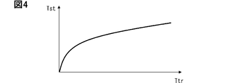
- the target steering torque control unit 112 estimates the actual steering torque Ttr applied to the steering tire 20 based on the value obtained by multiplying the steering current value It by a predetermined torque conversion coefficient and the actual steering torque Tsr. .. Further, the target steering torque control unit 112 determines the target steering torque Tst corresponding to the estimated actual steering torque Ttr based on, for example, the map shown in FIG.
- the target steering torque Tst is input from the target steering torque control unit 112 to the torque follow-up control unit 114.
- the actual steering torque Tsr is input from the steering torque sensor 52 to the torque follow-up control unit 114.
- the torque follow-up control unit 114 executes torque follow-up control such as PID control so that the actual steering torque Tsr follows the target steering torque Tst.
- the torque follow-up control unit 114 determines the candidate value of the steering current applied to the steering motor 30 as the second steering current candidate value Isc2.
- the stop command Oe and the automatic operation command Oa are input to the steering current selection unit 115 from the track generation unit 100.
- a stop command Oe is input from the start sensor 55 to the steering current selection unit 115.
- the first steering current candidate value Isc1 is input to the steering current selection unit 115 from the steering angle tracking control unit 113.
- the second steering current candidate value Isc2 is input from the torque follow-up control unit 114.
- the steering current selection unit 115 selects one of the first steering current candidate value Isc1 and the second steering current candidate value Isc2 as the steering current value Is according to the mode.
- the steering current selection unit 115 selects the first steering current candidate value Isc1 as the steering current value Is. Further, even when the stop command Oe is input from the trajectory generation unit 100 or the start sensor 55, the steering current selection unit 115 selects the first steering current candidate value Isc1 as the steering current value Is. From these things, in the automatic driving mode and the stop control mode of the vehicle 2, the first steering current candidate value Isc1 is selected as the steering current value Is.
- the steering current selection unit 115 selects the second steering current candidate value Isc2 as the steering current value Is.
- the second steering current candidate value Isc2 is selected as the steering current value Is.
- the steering current value Is is input from the steering current selection unit 115 to the steering tapering control unit 116.
- the steering gradual reduction command Or is input to the steering gradual reduction control unit 116 from the steering gradual reduction control unit 123 of the steering control unit 120, which will be described later.
- the steering tapering control unit 116 When the steering tapering command Or is not input, the steering tapering control unit 116 generates an output command Os for instructing the steering actuator 3 to apply the steering current value Is.
- the steering current value Is is the first steering current candidate value Isc1
- the actual steering angle ⁇ sr of the steering wheel 21 corresponds to the output command Os via the steering actuator 3 according to the generated output command Os. It is controlled by the angle.
- the steering current value Is is the second steering current candidate value Isc2
- the actual steering torque Tsr of the steering wheel 21 corresponds to the output command Os via the steering actuator 3 according to the generated output command Os. Is controlled by.
- the steering gradual reduction control unit 116 issues an output command Os for instructing the steering actuator 3 to apply the current value adjusted by the gradual reduction control described in detail later. Generate.
- the steering actuator 3 according to the generated output command Os controls the steering output torque Tso toward the steering wheel 21.
- the steering control unit 120 selectively controls the steering output torque Tto output from the steering actuator 4 and the actual steering angle ⁇ tr via the steering actuator 4. Run. Therefore, the steering control unit 120 has a target steering angle selection unit 121, a steering angle tracking control unit 122, and a steering gradual reduction control unit 123.
- the automatic operation command Oa and the planned track Tz are input from the track generation unit 100 to the target steering angle selection unit 121.
- the actual steering angle ⁇ sr is input from the steering angle sensor 53 to the target steering angle selection unit 121.
- the target turning angle selection unit 121 selects the target turning angle ⁇ tt, which is the control target of the actual turning angle ⁇ tr, based on these inputs.
- the target turning angle selection unit 121 selects the target turning angle ⁇ tt acquired so as to follow the planned track Tz.
- the target steering angle selection unit 121 executes interlocking control in which the actual steering angle ⁇ tr is interlocked with the actual steering angle ⁇ sr. In this interlocking control, the target steering angle selection unit 121 selects a conversion angle obtained by multiplying the actual steering angle ⁇ sr by a predetermined angle conversion ratio as the target steering angle ⁇ tt.
- the target steering angle ⁇ tt is input from the target steering angle selection unit 121 to the steering angle tracking control unit 122.
- the steering angle tracking control unit 122 executes steering angle tracking control such as PID control so that the actual steering angle ⁇ tr follows the target steering angle ⁇ tt.
- the steering angle tracking control unit 122 determines the steering current value It applied to the steering motor 40.
- the steering current value It is input from the steering angle tracking control unit 122 to the steering gradual reduction control unit 123.
- a stop command Oe is input from the track generation unit 100 to the steering gradual reduction control unit 123.
- a stop command Oe is input from the start sensor 55 to the steering gradual reduction control unit 123.
- the steering gradual reduction control unit 123 generates an output command Ot for instructing the steering actuator 4 to apply the steering current value It.
- the actual steering angle ⁇ tr of the steering tire 20 is controlled to an angle corresponding to the output command Ot via the steering actuator 4 according to the generated output command Ot.
- the steering gradual reduction control unit 123 issues an output command Ot for instructing the steering actuator 4 to apply the current value adjusted by the gradual reduction control described in detail later. , Generate.
- the steering actuator 4 according to the generated output command Ot controls the steering output torque Tto toward the steering tire 20.
- the steering output torque Tto substantially coincides with the actual steering torque Ttr of the steering tire 20.
- each "S" in FIG. 5 means a plurality of steps executed by a plurality of instructions included in a steering control program.
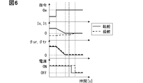
- FIG. 6 except for the graph of the stop command Oe, the change with time of the value related to steering is shown by the solid line, and the change with time of the value related to steering is shown by the dotted line.
- the target steering angle selection unit 111 selects the target steering angle ⁇ st so that the actual steering angle ⁇ sr is linked to the actual steering angle ⁇ tr in accordance with the stop command Oe.
- the selected target steering angle ⁇ st is converted to the first steering current candidate value Isc1 by the steering angle tracking control unit 113, and the conversion value Isc1 is used as the steering current value Is in accordance with the stop command Oe. It is input from the selection unit 115 to the steering tapering control unit 116.
- the steering gradual reduction control unit 123 executes the gradual reduction with respect to the steering current value It as shown in FIGS. 6 and 7 in response to the stop command Oe.
- the steering gradual reduction control unit 123 stores the steering current value It at the time of input of the stop command Oe as the initial value It0 of the steering current value It to be gradually reduced.
- the steering gradual reduction control unit 123 substantially continuously and gradually decreases the steering current value It from the initial value It0 so that the reduction rate of the steering current value It per unit time becomes constant.
- the steering gradual reduction control unit 123 outputs an output command Ot instructing the gradual reduction of the steering current value It to the steering actuator 4.
- the steering output torque Tto output from the steering actuator 4 to the steering tire 20 is controlled according to the output command Ot, so that the reduction rate per unit time is gradually reduced. ..
- the steering gradual reduction control unit 123 finishes the gradual reduction of the steering current value It, and then sends the steering gradual reduction command Or to the steering gradual reduction control unit 116. Is output.
- the gradual decrease of the steering current value It may be terminated when the steering current value It reaches a predetermined value close to the zero value.
- the steering gradual reduction control unit 116 responds to the steering gradual reduction command Or as shown in FIGS.
- the gradual decrease with respect to the steering current value Is is executed.
- the steering gradual reduction control unit 116 stores the steering current value Is at the time of input of the steering gradual reduction command Or as the initial value Is0 of the steering current value Is to be gradually reduced. Further, the steering gradual decrease control unit 116 substantially continuously decreases the steering current value Is from the initial value Is0 so that the decrease rate of the steering current value Is per unit time becomes constant.
- the steering gradual decrease control unit 116 outputs an output command Os that commands the gradual decrease of the steering current value Is to the steering actuator 3.
- the steering output torque Tso output from the steering actuator 3 to the steering wheel 21 is controlled according to the output command Os, so that the reduction rate per unit time is gradually reduced.
- the steering gradual decrease control unit 116 ends the gradual decrease of the steering current value Is.
- the gradual decrease of the steering current value Is may be terminated when the steering current value Is reaches a predetermined value close to the zero value.
- the steering gradual reduction control unit 123 cuts the energization from the steering driver 42 to the steering motor 40 in S104. ..
- the steering gradual decrease control unit 116 cuts the energization from the steering driver 32 to the steering motor 30 in S105.
- the execution time of S104 of the energization cut to the steering motor 30 and S105 of the energization cut to the steering motor 40 may be shifted back and forth (S104 is the previous example in FIGS. 5 and 6). It may be executed at substantially the same time.
- the energization cut to the steering motor 30 and the energization cut to the steering motor 40 are such that the corresponding drivers 32 and 42 cut off the power supply (off in FIG. 6). It will be realized. However, when the applied current is gradually reduced to the zero value in S102 and S103, it can be considered that the energization cut is realized when the zero value is reached.
- S101, S103, and S105 correspond to the steering control process
- S102 and S104 correspond to the steering control process
- the steering output torque Tto from the steering actuator 4 gradually decreases during the interlocking control in which the actual steering angle ⁇ sr is interlocked and controlled with respect to the actual steering angle ⁇ tr in accordance with the stop command Oe of the vehicle 2.
- the energization to the steering actuator 4 and the steering actuator 3 is cut off, respectively.
- the twist of the steering tire 20 can be gradually eliminated according to the gradual decrease control of the steering output torque Tto, so that the steering tire 20 can be untwisted. Rapid restoration is less likely to occur.
- the vibration of the steering wheel 21 interlocking with the steering tire 20 is also a stop command. It can be suppressed with Oe.
- the steering output torque Tto can be gradually and gradually reduced and controlled according to the gradually decreasing current by gradually reducing the current applied to the steering actuator 4. Therefore, it is possible to suppress the generation of vibration of the vehicle 2 due to the sudden restoration of the steering tire 20 in accordance with the stop command of the vehicle 2.
- the steering output torque Tto can be gradually reduced to the zero value by gradually reducing the current applied to the steering actuator 4 to the zero value. Therefore, the gentle twisting of the steering tire 20 can be continuously eliminated until the steering output torque Tto reaches a zero value, and the effect of suppressing the generation of vibration accompanying the stop command of the vehicle can be enhanced.
- the energization to the steering actuator 4 and the steering actuator 3 is cut. According to this, even if the steering output torque Tso remains after the interlocking control between the actual steering angle ⁇ sr and the actual steering angle ⁇ tr, the fluctuation and vibration of the steering wheel 21 due to the remaining torque Tso correspond to the gradual decrease. It can be mitigated by a gradual torque change. Therefore, it is possible to prevent the steering wheel 21 from being hindered by the effect of suppressing the generation of vibration accompanying the stop command Oe of the vehicle 2.
- the steering output torque Tso can be gradually and gradually reduced and controlled according to the gradually decreasing current by gradually reducing the current applied to the steering actuator 3. Therefore, it is possible to prevent the steering wheel 21 from being hindered by the effect of suppressing the generation of vibration accompanying the stop command Oe of the vehicle 2.
- the steering output torque Tso can be gradually reduced to a zero value by gradually reducing the current applied to the steering actuator 3 to a zero value. Therefore, the gradual decrease of the remaining steering output torque Tso can be continued until the steering output torque Tso becomes a zero value, and the deterrence of inhibition against the vibration generation accompanying the stop command Oe of the vehicle 2 can be enhanced.
- the energization of the steering actuator 4 and the steering actuator 3 is cut off by power cutoff after the steering output torque Tto and the steering output torque Tso are gradually reduced and controlled. According to this, even if the power is cut off due to the stop command Oe, it is possible to suppress the vibration generation of the steering tire 20 and the vehicle body due to the restoration of the steering tire 20.
- the second embodiment is a modification of the first embodiment.
- the configurations of the steering gradual reduction control unit 123 and the steering gradual reduction control unit 116 are different from those in the first embodiment.
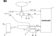
- the steering gradual reduction control unit 123 of the second embodiment includes a low-pass filter in which a cutoff frequency lower than the resonance frequency of the steering system 6 shown in FIG. 8 is set.
- the steering system 6 includes at least the steering tire 20 in the vehicle 2.
- the steering system 6 may include a steering actuator 4.
- the steering system 6 may include a driving member such as a tie rod, which is interposed between the steering actuator 4 and the steering tire 20.
- the steering gradual reduction control unit 123 gradually reduces the steering current value It by passing through a low-pass filter. As a result, as shown in FIG. 9, in addition to the steering current value It itself, the rate of decrease of the steering current value It per unit time is gradually reduced.
- the steering tapering control unit 116 of the second embodiment is configured to include a low-pass filter in which a predetermined cutoff frequency is set.
- the steering gradual decrease control unit 116 gradually decreases the steering current value Is by passing through a low-pass filter.
- the decrease rate of the steering current value Is per unit time is also gradually decreased.
- the current applied to the steering actuator 4 is gradually reduced by passing the vehicle 2 through a low-pass filter having a cutoff frequency set lower than the resonance frequency of the steering system 6 including the steering tire 20. Will be done. According to this, the vibration generation of the steering system 6 and the vehicle body due to the restoration of the steering tire 20 can be suppressed in accordance with the stop command Oe.
- the steering actuator 4 of the modified example may constitute a power steering system that is mechanically linked to the steering wheel 21 and the steering actuator 3 and can be controlled independently of the actuator 3.
- the dedicated computer constituting the steering control device 1 may be at least one external center computer capable of communicating with the vehicle 2.
- the dedicated computer constituting the steering control device 1 may include at least one of a digital circuit and an analog circuit as a processor.
- the digital circuit is, for example, among ASIC (Application Specific Integrated Circuit), FPGA (Field Programmable Gate Array), SOC (System on a Chip), PGA (Programmable Gate Array), CPLD (Complex Programmable Logic Device), and the like. , At least one type. Further, such a digital circuit may have a memory for storing a program.
- the steering current value It may be gradually decreased intermittently instead of gradually decreasing the steering current value It.
- the steering current value Is may be decreased intermittently instead of gradually decreasing the steering current value Is.
- the steering current value It may be gradually reduced so that the reduction rate gradually increases. ..
- the steering current value Is instead of gradually reducing the steering current value Is so that the reduction rate per unit time gradually decreases, the steering current value Is may be gradually reduced so that the reduction rate gradually increases.
- the first embodiment and the second embodiment may be combined. Specifically, only one of the steering gradual reduction control unit 123 and the steering gradual reduction control unit 116 may gradually reduce the applied current by a low-pass filter according to the second embodiment.
Landscapes
- Engineering & Computer Science (AREA)
- Chemical & Material Sciences (AREA)
- Combustion & Propulsion (AREA)
- Transportation (AREA)
- Mechanical Engineering (AREA)
- Steering Control In Accordance With Driving Conditions (AREA)
- Power Steering Mechanism (AREA)
Abstract
Un dispositif de commande de direction (1) comprend une unité de commande de direction (110) destinée à commander l'angle de direction réel (θsr) pour un volant de direction par l'intermédiaire d'un actionneur de direction (3) par la régulation d'un couple de sortie de direction (Tso) qui est délivré à partir de l'actionneur de direction (3), et une unité de commande de virage (120) destinée à commander l'angle de rotation réel (θtr) pour un pneu tourné par l'intermédiaire d'un actionneur de virage (4) par la régulation d'un couple de sortie de virage (Tto) qui est délivré par l'actionneur de virage (4). L'unité de commande de virage (120) régule le couple de sortie de virage (Tto) d'une manière décrémentielle pendant une commande conjonctive réalisée par l'unité de commande de direction (110) pour l'angle de direction réel (θsr) conjointement avec l'angle de virage réel (θtr) en réponse à une instruction d'arrêt de véhicule (Oe). L'unité de commande de virage (120) et l'unité de commande de direction (110) coupent l'alimentation électrique de l'actionneur de virage (4) et de l'actionneur de direction (3), respectivement, après la régulation décrémentielle du couple de sortie de virage (Tto) par l'unité de commande de virage (120).
Priority Applications (1)
| Application Number | Priority Date | Filing Date | Title |
|---|---|---|---|
| US18/302,650 US12428049B2 (en) | 2020-10-23 | 2023-04-18 | Steering control device, steering control method, and computer program product |
Applications Claiming Priority (2)
| Application Number | Priority Date | Filing Date | Title |
|---|---|---|---|
| JP2020178238A JP7388335B2 (ja) | 2020-10-23 | 2020-10-23 | 操舵制御装置、操舵制御方法、操舵制御プログラム |
| JP2020-178238 | 2020-10-23 |
Related Child Applications (1)
| Application Number | Title | Priority Date | Filing Date |
|---|---|---|---|
| US18/302,650 Continuation US12428049B2 (en) | 2020-10-23 | 2023-04-18 | Steering control device, steering control method, and computer program product |
Publications (1)
| Publication Number | Publication Date |
|---|---|
| WO2022085331A1 true WO2022085331A1 (fr) | 2022-04-28 |
Family
ID=81289854
Family Applications (1)
| Application Number | Title | Priority Date | Filing Date |
|---|---|---|---|
| PCT/JP2021/033316 Ceased WO2022085331A1 (fr) | 2020-10-23 | 2021-09-10 | Dispositif de commande de direction, procédé de commande de direction et programme de commande de direction |
Country Status (3)
| Country | Link |
|---|---|
| US (1) | US12428049B2 (fr) |
| JP (1) | JP7388335B2 (fr) |
| WO (1) | WO2022085331A1 (fr) |
Cited By (1)
| Publication number | Priority date | Publication date | Assignee | Title |
|---|---|---|---|---|
| US12428049B2 (en) * | 2020-10-23 | 2025-09-30 | Denso Corporation | Steering control device, steering control method, and computer program product |
Citations (6)
| Publication number | Priority date | Publication date | Assignee | Title |
|---|---|---|---|---|
| JP2014184739A (ja) * | 2013-03-21 | 2014-10-02 | Hitachi Automotive Systems Steering Ltd | パワーステアリング装置 |
| WO2018047846A1 (fr) * | 2016-09-06 | 2018-03-15 | Ntn株式会社 | Dispositif de transmission de rotation |
| WO2018088433A1 (fr) * | 2016-11-11 | 2018-05-17 | 日本精工株式会社 | Dispositif de direction assistée électrique |
| JP2018090057A (ja) * | 2016-12-01 | 2018-06-14 | 本田技研工業株式会社 | 乗員保持装置 |
| JP2019127216A (ja) * | 2018-01-26 | 2019-08-01 | 株式会社ジェイテクト | 転舵制御装置 |
| JP2020108327A (ja) * | 2018-12-27 | 2020-07-09 | 株式会社デンソー | 制御装置 |
Family Cites Families (21)
| Publication number | Priority date | Publication date | Assignee | Title |
|---|---|---|---|---|
| US4914382A (en) * | 1987-10-14 | 1990-04-03 | Hydro-Quebec | High voltage measuring circuit coupled to the capacitive grounding tap bushing of an HV device |
| JP4916820B2 (ja) * | 2006-08-29 | 2012-04-18 | 富士重工業株式会社 | 車両の操舵制御装置 |
| JP2008238943A (ja) | 2007-03-27 | 2008-10-09 | Mitsuba Corp | 車両用制御装置 |
| JP5003427B2 (ja) * | 2007-11-20 | 2012-08-15 | トヨタ自動車株式会社 | 操舵制御装置及びこれを用いた車両用操舵装置 |
| EP2213546B1 (fr) * | 2007-11-27 | 2014-08-20 | Mitsubishi Electric Corporation | Dispositif de commande de la direction |
| CN103228522B (zh) * | 2010-11-29 | 2016-05-25 | 日产自动车株式会社 | 车辆及其转向操纵控制方法 |
| CN104290806B (zh) * | 2013-07-16 | 2016-10-05 | 本田技研工业株式会社 | 车辆用转向装置 |
| CN106170432B (zh) * | 2014-04-25 | 2019-01-01 | 三菱电机株式会社 | 转向控制装置及其转向辅助转矩控制方法 |
| JP2017007484A (ja) * | 2015-06-22 | 2017-01-12 | 日立オートモティブシステムズ株式会社 | 自動操舵機能を持つ車両操舵装置 |
| CN106849823B (zh) * | 2017-02-24 | 2019-08-16 | 中国第一汽车股份有限公司 | 电动汽车主动减振控制方法 |
| KR102224996B1 (ko) * | 2017-06-30 | 2021-03-10 | 현대모비스 주식회사 | 전동식 파워 스티어링 시스템의 토크 보상 장치 및 방법 |
| JP6888531B2 (ja) | 2017-11-29 | 2021-06-16 | トヨタ自動車株式会社 | ステアバイワイヤシステム |
| US11479291B2 (en) | 2018-12-27 | 2022-10-25 | Denso Corporation | Control apparatus |
| US11964713B2 (en) * | 2019-05-29 | 2024-04-23 | Nsk Ltd. | Vehicle steering device |
| JP7389605B2 (ja) * | 2019-10-01 | 2023-11-30 | 日立Astemo株式会社 | 操舵制御装置 |
| JP7480509B2 (ja) * | 2020-01-13 | 2024-05-10 | 株式会社デンソー | 操舵制御装置、操舵制御方法、操舵制御プログラム |
| JP7388335B2 (ja) * | 2020-10-23 | 2023-11-29 | 株式会社デンソー | 操舵制御装置、操舵制御方法、操舵制御プログラム |
| JP7744168B2 (ja) * | 2021-07-13 | 2025-09-25 | 株式会社ジェイテクト | 操舵制御装置 |
| EP4474249A4 (fr) * | 2022-02-03 | 2025-05-21 | JTEKT Corporation | Dispositif de commande de direction et procédé de commande de direction |
| JP2024121271A (ja) * | 2023-02-27 | 2024-09-06 | トヨタ自動車株式会社 | ステアバイワイヤ式操舵装置 |
| CN119218294A (zh) * | 2023-06-29 | 2024-12-31 | 尼得科株式会社 | 控制装置和转向装置 |
-
2020
- 2020-10-23 JP JP2020178238A patent/JP7388335B2/ja active Active
-
2021
- 2021-09-10 WO PCT/JP2021/033316 patent/WO2022085331A1/fr not_active Ceased
-
2023
- 2023-04-18 US US18/302,650 patent/US12428049B2/en active Active
Patent Citations (6)
| Publication number | Priority date | Publication date | Assignee | Title |
|---|---|---|---|---|
| JP2014184739A (ja) * | 2013-03-21 | 2014-10-02 | Hitachi Automotive Systems Steering Ltd | パワーステアリング装置 |
| WO2018047846A1 (fr) * | 2016-09-06 | 2018-03-15 | Ntn株式会社 | Dispositif de transmission de rotation |
| WO2018088433A1 (fr) * | 2016-11-11 | 2018-05-17 | 日本精工株式会社 | Dispositif de direction assistée électrique |
| JP2018090057A (ja) * | 2016-12-01 | 2018-06-14 | 本田技研工業株式会社 | 乗員保持装置 |
| JP2019127216A (ja) * | 2018-01-26 | 2019-08-01 | 株式会社ジェイテクト | 転舵制御装置 |
| JP2020108327A (ja) * | 2018-12-27 | 2020-07-09 | 株式会社デンソー | 制御装置 |
Cited By (1)
| Publication number | Priority date | Publication date | Assignee | Title |
|---|---|---|---|---|
| US12428049B2 (en) * | 2020-10-23 | 2025-09-30 | Denso Corporation | Steering control device, steering control method, and computer program product |
Also Published As
| Publication number | Publication date |
|---|---|
| JP7388335B2 (ja) | 2023-11-29 |
| US20230257020A1 (en) | 2023-08-17 |
| US12428049B2 (en) | 2025-09-30 |
| JP2022069191A (ja) | 2022-05-11 |
Similar Documents
| Publication | Publication Date | Title |
|---|---|---|
| JP6489135B2 (ja) | 車両の運転支援装置 | |
| US12337906B2 (en) | Steering control device, steering control method, and non-transitory computer readable storage medium | |
| CN110356471B (zh) | 车辆控制系统 | |
| US11939013B2 (en) | Steering control device | |
| US20220348253A1 (en) | Steering control device, steering control method, and computer program product | |
| CN111483517A (zh) | 车辆控制系统 | |
| US11577781B2 (en) | Vehicle control system | |
| JP6387915B2 (ja) | 車両の運転支援制御装置 | |
| WO2022085331A1 (fr) | Dispositif de commande de direction, procédé de commande de direction et programme de commande de direction | |
| US20230127678A1 (en) | Vehicle driving support device | |
| JP2019119298A (ja) | 車両用制御装置 | |
| CN108216353B (zh) | 车辆控制装置 | |
| US12227239B2 (en) | Steering control device, and steering control method | |
| US12258022B2 (en) | Vehicle control device, vehicle, and vehicle control method | |
| JP2018197078A (ja) | 操舵支援装置、操舵支援方法及びプログラム | |
| CN117999209A (zh) | 车辆用控制装置、车辆用控制程序以及车辆控制方法 | |
| WO2018235930A1 (fr) | Dispositif de commande de déplacement | |
| JP2025009378A (ja) | 車両制御プログラム | |
| CN121157912A (zh) | 车辆的控制装置、控制程序产品以及控制方法 | |
| CN118683501A (zh) | 运动管理器以及信息处理方法 | |
| CN121157913A (zh) | 车辆的控制装置、控制程序产品以及控制方法 | |
| WO2021161676A1 (fr) | Dispositif, procédé et programme de commande de direction |
Legal Events
| Date | Code | Title | Description |
|---|---|---|---|
| 121 | Ep: the epo has been informed by wipo that ep was designated in this application |
Ref document number: 21882472 Country of ref document: EP Kind code of ref document: A1 |
|
| NENP | Non-entry into the national phase |
Ref country code: DE |
|
| 122 | Ep: pct application non-entry in european phase |
Ref document number: 21882472 Country of ref document: EP Kind code of ref document: A1 |