WO2022085600A1 - Boîte de connexion électrique - Google Patents
Boîte de connexion électrique Download PDFInfo
- Publication number
- WO2022085600A1 WO2022085600A1 PCT/JP2021/038318 JP2021038318W WO2022085600A1 WO 2022085600 A1 WO2022085600 A1 WO 2022085600A1 JP 2021038318 W JP2021038318 W JP 2021038318W WO 2022085600 A1 WO2022085600 A1 WO 2022085600A1
- Authority
- WO
- WIPO (PCT)
- Prior art keywords
- bus bar
- tab
- side bus
- fuse
- fuses
- Prior art date
- Legal status (The legal status is an assumption and is not a legal conclusion. Google has not performed a legal analysis and makes no representation as to the accuracy of the status listed.)
- Ceased
Links
Images






Classifications
-
- B—PERFORMING OPERATIONS; TRANSPORTING
- B60—VEHICLES IN GENERAL
- B60R—VEHICLES, VEHICLE FITTINGS, OR VEHICLE PARTS, NOT OTHERWISE PROVIDED FOR
- B60R16/00—Electric or fluid circuits specially adapted for vehicles and not otherwise provided for; Arrangement of elements of electric or fluid circuits specially adapted for vehicles and not otherwise provided for
- B60R16/02—Electric or fluid circuits specially adapted for vehicles and not otherwise provided for; Arrangement of elements of electric or fluid circuits specially adapted for vehicles and not otherwise provided for electric constitutive elements
- B60R16/023—Electric or fluid circuits specially adapted for vehicles and not otherwise provided for; Arrangement of elements of electric or fluid circuits specially adapted for vehicles and not otherwise provided for electric constitutive elements for transmission of signals between vehicle parts or subsystems
- B60R16/0238—Electrical distribution centers
-
- H—ELECTRICITY
- H02—GENERATION; CONVERSION OR DISTRIBUTION OF ELECTRIC POWER
- H02G—INSTALLATION OF ELECTRIC CABLES OR LINES, OR OF COMBINED OPTICAL AND ELECTRIC CABLES OR LINES
- H02G3/00—Installations of electric cables or lines or protective tubing therefor in or on buildings, equivalent structures or vehicles
- H02G3/02—Details
- H02G3/08—Distribution boxes; Connection or junction boxes
- H02G3/081—Bases, casings or covers
-
- B—PERFORMING OPERATIONS; TRANSPORTING
- B60—VEHICLES IN GENERAL
- B60R—VEHICLES, VEHICLE FITTINGS, OR VEHICLE PARTS, NOT OTHERWISE PROVIDED FOR
- B60R16/00—Electric or fluid circuits specially adapted for vehicles and not otherwise provided for; Arrangement of elements of electric or fluid circuits specially adapted for vehicles and not otherwise provided for
- B60R16/02—Electric or fluid circuits specially adapted for vehicles and not otherwise provided for; Arrangement of elements of electric or fluid circuits specially adapted for vehicles and not otherwise provided for electric constitutive elements
-
- H—ELECTRICITY
- H01—ELECTRIC ELEMENTS
- H01R—ELECTRICALLY-CONDUCTIVE CONNECTIONS; STRUCTURAL ASSOCIATIONS OF A PLURALITY OF MUTUALLY-INSULATED ELECTRICAL CONNECTING ELEMENTS; COUPLING DEVICES; CURRENT COLLECTORS
- H01R13/00—Details of coupling devices of the kinds covered by groups H01R12/70 or H01R24/00 - H01R33/00
- H01R13/648—Protective earth or shield arrangements on coupling devices, e.g. anti-static shielding
- H01R13/658—High frequency shielding arrangements, e.g. against EMI [Electro-Magnetic Interference] or EMP [Electro-Magnetic Pulse]
- H01R13/6581—Shield structure
-
- H—ELECTRICITY
- H01—ELECTRIC ELEMENTS
- H01R—ELECTRICALLY-CONDUCTIVE CONNECTIONS; STRUCTURAL ASSOCIATIONS OF A PLURALITY OF MUTUALLY-INSULATED ELECTRICAL CONNECTING ELEMENTS; COUPLING DEVICES; CURRENT COLLECTORS
- H01R13/00—Details of coupling devices of the kinds covered by groups H01R12/70 or H01R24/00 - H01R33/00
- H01R13/66—Structural association with built-in electrical component
- H01R13/68—Structural association with built-in electrical component with built-in fuse
-
- B—PERFORMING OPERATIONS; TRANSPORTING
- B60—VEHICLES IN GENERAL
- B60R—VEHICLES, VEHICLE FITTINGS, OR VEHICLE PARTS, NOT OTHERWISE PROVIDED FOR
- B60R16/00—Electric or fluid circuits specially adapted for vehicles and not otherwise provided for; Arrangement of elements of electric or fluid circuits specially adapted for vehicles and not otherwise provided for
- B60R16/02—Electric or fluid circuits specially adapted for vehicles and not otherwise provided for; Arrangement of elements of electric or fluid circuits specially adapted for vehicles and not otherwise provided for electric constitutive elements
- B60R16/03—Electric or fluid circuits specially adapted for vehicles and not otherwise provided for; Arrangement of elements of electric or fluid circuits specially adapted for vehicles and not otherwise provided for electric constitutive elements for supply of electrical power to vehicle subsystems or for
- B60R16/033—Electric or fluid circuits specially adapted for vehicles and not otherwise provided for; Arrangement of elements of electric or fluid circuits specially adapted for vehicles and not otherwise provided for electric constitutive elements for supply of electrical power to vehicle subsystems or for characterised by the use of electrical cells or batteries
-
- H—ELECTRICITY
- H01—ELECTRIC ELEMENTS
- H01R—ELECTRICALLY-CONDUCTIVE CONNECTIONS; STRUCTURAL ASSOCIATIONS OF A PLURALITY OF MUTUALLY-INSULATED ELECTRICAL CONNECTING ELEMENTS; COUPLING DEVICES; CURRENT COLLECTORS
- H01R2201/00—Connectors or connections adapted for particular applications
- H01R2201/26—Connectors or connections adapted for particular applications for vehicles
-
- Y—GENERAL TAGGING OF NEW TECHNOLOGICAL DEVELOPMENTS; GENERAL TAGGING OF CROSS-SECTIONAL TECHNOLOGIES SPANNING OVER SEVERAL SECTIONS OF THE IPC; TECHNICAL SUBJECTS COVERED BY FORMER USPC CROSS-REFERENCE ART COLLECTIONS [XRACs] AND DIGESTS
- Y02—TECHNOLOGIES OR APPLICATIONS FOR MITIGATION OR ADAPTATION AGAINST CLIMATE CHANGE
- Y02E—REDUCTION OF GREENHOUSE GAS [GHG] EMISSIONS, RELATED TO ENERGY GENERATION, TRANSMISSION OR DISTRIBUTION
- Y02E10/00—Energy generation through renewable energy sources
- Y02E10/50—Photovoltaic [PV] energy
Definitions
- This disclosure relates to an electrical junction box.
- Patent Documents 1 and 2 vehicles such as automobiles are provided with an electrical connection box such as a junction box.
- An electric wire connected to a battery provided in the vehicle body and various electric parts is connected to the electric junction box.
- a vehicle such as an electric vehicle is provided with an electric connection box (junction box or the like) provided with a high-voltage circuit to which a high-voltage electric wire is connected. High-voltage power lines that connect to the battery installed in the vehicle body and various electrical components are connected to the electrical junction box.
- JP-A-2002-044835 Japanese Unexamined Patent Publication No. 2005-033882 Japanese Unexamined Patent Publication No. 2014-212608
- a metal housing is required as a countermeasure against electromagnetic noise based on the high-voltage voltage, so there is room for improvement in terms of miniaturization.
- the purpose of this disclosure is to provide an electrical connection box that can be miniaturized.
- the electrical connection box of the present disclosure includes a metal housing, a plus-side bus bar housed in the housing, and a minus-side bus bar housed in the housing and formed so as to surround the plus-side bus bar. Equipped with.
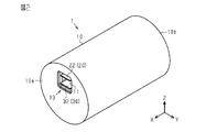
- FIG. 1 is a perspective view of the electrical connection box of the first embodiment.
- FIG. 2 is a perspective view of the electrical connection box of the first embodiment.
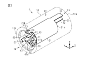
- FIG. 3 is a perspective view showing the internal configuration of the electrical connection box of the first embodiment.
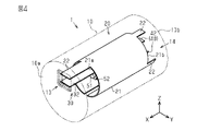
- FIG. 4 is a perspective view showing the internal configuration of the electrical connection box of the first embodiment.
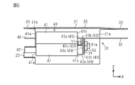
- FIG. 5 is a cross-sectional view of the electrical connection box of the first embodiment.
- FIG. 6 is a side view showing a bus bar and a fuse.
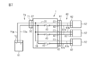
- FIG. 7 is a block circuit diagram showing the connection of the electrical junction box of the first embodiment.
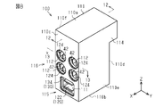
- FIG. 8 is a perspective view of the electrical connection box of the second embodiment.
- FIG. 9 is a perspective view of the electrical connection box of the second embodiment.
- FIG. 1 is a perspective view of the electrical connection box of the first embodiment.
- FIG. 2 is a perspective view of the electrical connection box of the first embodiment.
- FIG. 3 is a perspective view showing the internal configuration of the electrical connection box of the
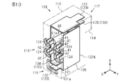
- FIG. 10 is a perspective view showing the internal configuration of the electrical connection box of the second embodiment.
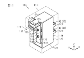
- FIG. 11 is a perspective view showing the internal configuration of the electrical connection box of the second embodiment.
- FIG. 12 is a cross-sectional view taken along the line 12-12 of FIG.
- FIG. 13 is a cross-sectional view taken along the line 13-13 of FIG.
- FIG. 14 is a block circuit diagram showing the connection of the electrical junction box of the second embodiment.
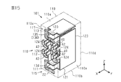
- FIG. 15 is a perspective view showing the internal configuration of the electrical connection box of the modified example.
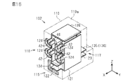
- FIG. 16 is a perspective view showing the internal configuration of the electrical connection box of the modified example.
- FIG. 17 is a perspective view showing the internal configuration of the electrical connection box of the modified example.
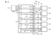
- FIG. 18 is a block circuit diagram showing the connection of the electrical junction box of the modified example.
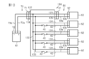
- FIG. 19 is a block circuit diagram showing the connection of the electrical junction box of the modified example.
- a metal housing, a plus-side bus bar housed in the housing, and a minus-side bus bar housed in the housing and formed so as to surround the plus-side bus bar are provided.
- the minus side bus bar surrounding the plus side bus bar and the metal housing play a role of noise shielding, so that the thickness of the metal housing can be reduced and the electric junction box can be downsized. be able to.
- At least three fuses surrounded by the minus side bus bar are provided, each of the fuses has a columnar main body portion, and the fuses are arranged so that the main body portion is along the first direction. , One of the at least three fuses is arranged in a second direction intersecting the first direction with respect to one of the remaining at least two fuses, and the other of the remaining at least two fuses. It is preferable that one is arranged in the first direction and the third direction intersecting with the second direction.
- the fuse has a first male tab provided on the first end surface of the main body portion and a fixing tab provided on the second end surface of the main body portion, and the first male tab is the plus. It is preferably at the same potential as the side bus bar.
- the portion having the same potential as the positive bus bar is surrounded by the negative bus bar, and noise is suppressed.
- the fixing tab of the fuse is electrically connected to the plus side bus bar.
- the first male tab of the fuse can be equipotential with the positive bus bar.
- the minus side bus bar preferably has a second male tab facing the first male tab of the fuse.
- the devices can be connected directly or via an electric wire.
- the plus side bus bar has a plus side connection tab
- the minus side bus bar has a minus side connection tab arranged to face the plus side connection tab.
- the positive side connection tab and the negative side connection tab arranged opposite to each other form a pair to form a connection terminal, so that the devices can be connected directly or via an electric wire.
- Specific examples of the electrical junction box of the present disclosure will be described below with reference to the drawings. In each drawing, for convenience of explanation, a part of the configuration may be exaggerated or simplified. In addition, the dimensional ratio of each part may differ in each drawing.
- the term "parallel” or “orthogonal” in the present specification includes not only the case of strictly parallel or orthogonal, but also the case of being substantially parallel or orthogonal within the range in which the action and effect in the present embodiment are exhibited. It should be noted that the present invention is not limited to these examples, and is indicated by the scope of claims, and is intended to include all modifications within the meaning and scope equivalent to the scope of claims.
- the electrical connection box 1 of the present embodiment has a housing 10 formed in a columnar shape.
- the housing 10 is made of metal.
- the housing 10 has a circular first end surface 10a and a second end surface 10b.
- the direction in which the first end surface 10a faces is the X direction
- one of the radial directions of the circular first end surface 10a is the Y direction
- the direction orthogonal to the X direction and the Y direction is the Z direction. do.
- the housing 10 of the present embodiment is formed in a columnar shape having a central axis in the X direction.
- a first connection recess 11 is formed on the first end surface 10a of the housing 10.
- the electrical connection box 1 has a first external terminal 13 (first connection terminal) provided in the first connection recess 11.
- the first external terminal 13 includes a positive side connection tab 32 and a negative side connection tab 22.
- a second connection recess 12 is formed on the second end surface 10b of the housing 10.
- the electrical connection box 1 has a second external terminal 14 (second connection terminal) provided in the second connection recess 12.
- the second external terminal 14 includes a plurality of first male tabs 42 and second male tabs 23. In this embodiment, the second external terminal 14 includes three pairs of first male tab 42 and second male tab 23.
- the first connection recess 11 is for inserting the connector 71 shown in FIG. 7.
- the connector 71 is provided in the wire harness 70 that connects the electrical connection box 1 and the device 61.
- the wire harness 70 includes a connector 71, a connector 72 connected to the device 61, and electric wires 73a and 73b between the connector 71 and the connector 72.
- the device 61 is an electric device provided in the vehicle, for example, a battery pack, a charge / discharge controller connected to the battery pack, and the like.
- the device 61 includes a positive side terminal and a negative side terminal, and the positive side terminal and the negative side terminal are connected to the electric wires 73a and 73b.
- the positive side connection tab 32 and the negative side connection tab 22 of the first external terminal 13 of the electric connection box 1 are connected to the positive side terminal and the negative side terminal of the device 61 via the electric wires 73a and 73b of the wire harness 70.
- the second connection recess 12 of the second end surface 10b shown in FIG. 2 is for inserting the connector 81 shown in FIG. 7.
- the connector 81 is provided in the wire harness 80 that connects the electrical connection box 1 and the plurality of devices 62.
- the wire harness 80 includes a connector 81, a connector 82 connected to the device 62, and electric wires 83a and 83b between the connector 81 and the connector 82.
- the device 62 is an electric device provided in the vehicle, for example, a motor, a unit for driving the motor, a voltage converter, a low voltage battery unit, and the like.
- Each of the devices 62 includes a positive side terminal and a negative side terminal, and the positive side terminal and the negative side terminal form a second external terminal 14 of the electric junction box 1 via the electric wires 83a and 83b of the wire harness 80. It is connected to the first male tab 42 and the second male tab 23.
- the electrical connection box 1 includes a minus side bus bar 20, a plus side bus bar 30, and a plurality of (three in this embodiment) fuses 40, which are housed in a housing 10. There is.
- the fuse 40 includes a main body 41, a first male tab 42, and a fixed tab 43.
- the main body 41 is formed in a columnar shape and has a first end surface 41a and a second end surface 41b.
- the first male tab 42 is formed so as to protrude from the first end surface 41a of the main body 41.
- the fixing tab 43 is formed so as to protrude from the second end surface 41b of the main body portion 41.
- the fixing tab 43 has an extending portion 43a extending from the main body portion 41 and a connecting portion 43b extending from the tip of the extending portion 43a in a direction orthogonal to the extending portion 43a.
- a through hole 43c is formed in the connection portion 43b.
- a bolt 51 for fixing the fuse 40 is inserted through the through hole 43c.
- the fuse 40 of this embodiment is connected to each other by a bolt 51 and a nut 52.
- the three fuses 40 are connected to each other by one bolt 51 and a nut 52. Such fuses 40 are arranged in a three-dimensional (3D) shape. More specifically, the fuses 40 are arranged at equal intervals along the circumferential direction of the circle centered on the bolt 51. In other words, the three fuses 40 are arranged on each side (each vertex) of an equilateral triangle centered on the bolt 51. That is, the three fuses 40 are arranged in a direction along one side of the equilateral triangle and in a direction along one side different from that side.
- 3D three-dimensional
- Box 1 can be miniaturized.
- the plus side bus bar 30 has a fixed portion 31 and a plus side connection tab 32.
- the fixing portion 31 and the positive side connecting tab 32 extend in a direction orthogonal to each other.
- the plus side bus bar 30 is formed in an L shape by the fixing portion 31 and the plus side connection tab 32.
- a through hole 31a is formed in the fixing portion 31.
- a bolt 51 for fixing the fuse 40 is inserted through the through hole 31a. That is, the fixing tab 43 of the fuse 40 and the plus side bus bar 30 of the present embodiment are connected to each other by the bolt 51 and the nut 52.
- the fixed tab 43 of each fuse 40 has the same potential as the positive bus bar 30.
- the first male tab 42 of each fuse 40 has the same potential as the positive bus bar 30.
- the minus side bus bar 20 is formed so as to surround the plus side bus bar 30. More specifically, the negative bus bar 20 is formed so as to surround a portion having the same potential as the positive bus bar 30. That is, the minus side bus bar 20 is formed so as to surround the plus side bus bar 30 and each fuse 40 connected to the plus side bus bar 30.
- the minus side bus bar 20 is made of metal.
- the metal minus-side bus bar 20 plays a role of electromagnetic noise countermeasures, that is, noise shielding for the plus-side bus bar 30 and the fuse 40 surrounded by the minus-side bus bar 20.
- the metal housing 10 accommodating the minus side bus bar 20, the plus side bus bar 30, and the fuse 40 plays a role of electromagnetic noise countermeasures, that is, noise shielding.
- the metal housing 10 and the metal minus side bus bar 20 play a role of noise shielding. Therefore, the metal housing 10 can be made thinner, and the electrical connection box 1 can be made smaller.
- the minus side bus bar 20 of the present embodiment is formed in a substantially cylindrical shape.
- the minus side bus bar 20 is formed by rolling a metal flat plate into a cylindrical shape.
- the minus side bus bar 20 includes a main body portion 21, one minus side connection tab 22, and three second male tabs 23.
- the main body portion 21 is formed in a cylindrical shape and has a first end portion 21a on the side of the first end surface 10a of the housing 10 and a second end portion 21b on the side of the second end surface 10b of the housing 10. There is.
- the negative side connection tab 22 is formed so as to protrude from the first end portion 21a of the main body portion 21.
- the three second male tabs 23 are formed so as to project from the second end portion 21b of the main body portion 21.
- the three second male tabs 23 are arranged at equal intervals along the circumferential surface of the cylindrical main body portion 21.
- the second male tab 23 is arranged so as to face the first male tab 42 of the fuse 40.
- the positive side connection tab 32 and the negative side connection tab 22 are paired and function as connection terminals for connecting the positive side electric wire 73a and the negative side electric wire 73b shown in FIG. 7. Further, the first male tab 42 and the second male tab 23 are paired and function as connection terminals for connecting the positive side electric wire 83a and the negative side electric wire 83b shown in FIG. 7.
- the electrical connection box 1 is formed so as to surround the metal housing 10, the plus-side bus bar 30 housed in the housing 10, and the plus-side bus bar 30 housed in the housing 10. It was equipped with a minus side bus bar 20.
- the minus side bus bar 20 surrounding the plus side bus bar 30 plays a role of noise shielding together with the metal housing 10. Therefore, by providing the minus side bus bar 20 surrounding the plus side bus bar 30, the thickness of the metal housing 10 accommodating the minus side bus bar 20 and the plus side bus bar 30 can be reduced, and the electric junction box 1 can be downsized. Can be planned. Then, by downsizing the electric connection box 1, the degree of freedom in the arrangement of the electric connection box 1 can be improved in the vehicle on which the electric connection box 1 is mounted.
- each of the fuses 40 has a columnar main body 41, and the fuse 40 is arranged so that the main body 41 is along the first direction.
- One of the three fuses 40 is arranged in a second direction intersecting the first direction with respect to one of the remaining two fuses 40 and with respect to the other one of the remaining two fuses 40. They are arranged in the first direction and the third direction that intersects the second direction.
- the fuse 40 has a first male tab 42 on the first end surface 41a of the main body 41 and a fixing tab 43 on the second end surface 41b of the main body 41, and the first male tab 42 is a plus side bus bar. It is the same potential as 30. A portion having the same potential as the positive bus bar 30 is surrounded by the negative bus bar 20, and noise can be suppressed.
- the fixing tab 43 of the fuse 40 is electrically connected to the plus side bus bar 30. Therefore, the first male tab 42 of the fuse 40 can be at the same potential as the positive bus bar 30.
- the minus side bus bar 20 has a second male tab 23 arranged to face the first male tab 42 of the fuse 40.
- the first male tab 42 and the second male tab 23 arranged to face each other form a pair to form the second external terminal 14, and the electrical connection box 1 and the device 62 can be easily connected.
- the plus side bus bar 30 has a plus side connection tab 32
- the minus side bus bar 20 has a minus side connection tab 22 arranged opposite to the plus side connection tab 32.
- the positive side connection tab 32 and the negative side connection tab 22 arranged to face each other form a pair to form the first external terminal 13, and the electrical connection box 1 and the device 61 can be easily connected. can.
- the electrical connection box 100 of the present embodiment has a substantially rectangular parallelepiped housing 110.
- the housing 110 is made of metal.
- the housing 110 has an upper surface 110a and a lower surface 110b, and a first side surface 110c to a fourth side surface 110f.
- the upper surface 110a and the lower surface 110b face each other in the Z direction, which is the height direction.
- the first side surface 110c and the second side surface 110d face each other in the X direction orthogonal to the Z direction.
- the third side surface 110e and the fourth side surface 110f face opposite to each other in the Z direction and the Y direction orthogonal to the X direction.
- the first side surface 110c is formed with a first connection recess 111 and a plurality of (four in this embodiment) second connection recess 112.
- a third connection recess 113 is formed on the second side surface 110d.
- the third connection recess 113 is provided on the side of the upper surface 110a of the housing 110.
- the housing 110 has a protrusion 114 that protrudes from the second side surface 110d, and the protrusion 114 is provided with a third connection recess 113.
- the electrical connection box 100 includes a first external terminal 115 (first connection terminal) provided in the first connection recess 111.
- the first external terminal 115 is composed of a positive side connection tab 134 and a negative side connection tab 122.
- the electrical connection box 100 includes a second external terminal 116 (second connection terminal) provided in each of the second connection recesses 112.
- the second external terminal 116 is composed of a first male tab 42 and a second male tab 124.
- the electrical connection box 100 includes a third external terminal 117 (third connection terminal) provided in the third connection recess 113.
- the third external terminal 117 is composed of a positive side connection tab 135 and a negative side connection tab 123.
- the first connection recess 111 is for inserting the connector 71 shown in FIG.
- the connector 71 is provided on the wire harness 70 that connects the electrical junction box 100 and the device 61.
- the wire harness 70 includes a connector 71, a connector 72 connected to the device 61, and electric wires 73a and 73b between the connector 71 and the connector 72.
- the device 61 is an electric device provided in the vehicle, for example, a battery pack, a charge / discharge controller connected to the battery pack, and the like.
- the device 61 includes a positive side terminal and a negative side terminal, and the positive side terminal and the negative side terminal are connected to the electric wires 73a and 73b.
- the positive side connection tab 134 and the negative side connection tab 122 of the first external terminal 115 of the electric connection box 100 are connected to the positive side terminal and the negative side terminal of the device 61 via the electric wires 73a and 73b of the wire harness 70.
- the second connection recess 112 is for inserting the connector 81a shown in FIG.
- the connector 81a is provided on the wire harness 80a that connects the electrical junction box 100 and the device 62.
- the wire harness 80a includes a connector 81a, a connector 82 connected to the device 62, and electric wires 83a and 83b between the connector 81a and the connector 82.
- the device 62 is an electric device provided in the vehicle, for example, a motor, a unit for driving the motor, a voltage converter, a low voltage battery unit, and the like.
- the device 62 includes a positive side terminal and a negative side terminal, and the positive side terminal and the negative side terminal are connected to the second external terminal 116 of the electric junction box 100 via the electric wires 83a and 83b of the wire harness 80a. ..
- the third connection recess 113 is for inserting the connector 91 shown in FIG.
- the connector 91 is provided on the wire harness 90 that connects the electrical junction box 100 and the device 63.
- the wire harness 90 includes a connector 91, a connector 92 connected to the device 63, and electric wires 93a and 93b between the connector 91 and the connector 92.
- the device 63 is an electric device provided in the vehicle, for example, a charging port for charging a battery pack.
- the device 63 includes a positive side terminal and a negative side terminal, and the positive side terminal and the negative side terminal are connected to the electric wires 93a and 93b.
- the positive side connection tab 135 and the negative side connection tab 123 of the third external terminal 117 of the electric connection box 100 are connected to the positive side terminal and the negative side terminal of the device 63 via the electric wires 93a and 93b of the wire harness 90.
- the electrical junction box 100 includes a minus side bus bar 120, a plus side bus bar 130, and a plurality of (four in this embodiment) fuses 40, which are housed in a housing 110. There is.
- the two fuses 40 arranged near the upper surface 110a of the housing 110 are connected to each other by bolts 51 and nuts 52, and the fixing tab 43 of each fuse 40 is fixed to the plus side bus bar 130.
- the two fuses 40 arranged closer to the lower surface 110b of the housing 110 are connected to each other by bolts 53 and nuts 54, and the fixing tab 43 of each fuse 40 is fixed to the plus side bus bar 130.
- the fuse 40 is arranged three-dimensionally (in a 3D shape).
- the four fuses 40 may be fixed to the plus side bus bar 130 with a set of bolts and nuts.
- the density can be increased and the volume indicated by the four fuses 40 can be reduced as compared with the case where the four fuses 40 are arranged in a row, and the electric junction box 100 can be made smaller. Can be changed.
- the plus side bus bar 130 has a first portion 131 extending in the X direction along the lower surface 110b of the housing 110 and a second side surface of the housing 110 from the first portion 131. It includes a second portion 132 extending in the Z direction along 110d and a third portion 133 extending in the X direction from the second portion 132.
- the fuse 40 is fixed to a second portion 132 extending in the Z direction. In this embodiment, the fuses 40 are arranged in the Y direction and the Z direction.
- the plus-side bus bar 130 has a plus-side connection tab 134 at the tip of the first portion 131 and a plus-side connection tab 135 at the tip of the third portion 133.
- the minus side bus bar 120 is formed so as to surround the plus side bus bar 130. More specifically, the negative bus bar 120 is formed so as to surround a portion having the same potential as the positive bus bar 130. That is, the minus side bus bar 120 is formed so as to surround the plus side bus bar 130 and the fuse 40 connected to the plus side bus bar 130.
- the minus side bus bar 120 is made of metal.
- the metal minus-side bus bar 120 plays a role of electromagnetic noise countermeasures, that is, noise shielding for the plus-side bus bar 130 and the fuse 40 surrounded by the minus-side bus bar 120.
- the metal housing 110 accommodating the minus side bus bar 120, the plus side bus bar 130, and the fuse 40 plays a role of electromagnetic noise countermeasures, that is, noise shielding.
- the metal housing 110 and the metal minus side bus bar 120 play a role of noise shielding. Therefore, the metal housing 110 can be made thinner, and the electrical connection box 100 can be made smaller.
- the minus side bus bar 120 of the present embodiment is formed in the shape of a quadrangular cylinder.
- the minus side bus bar 120 is formed in the shape of a quadrangular cylinder by bending a metal flat plate.
- the minus-side bus bar 120 includes a main body 121, two minus-side connection tabs 122 and 123, and four second male tabs 124.
- the main body portion 121 is formed in a quadrangular cylindrical shape, and has a first end portion 121a on the side of the first side surface 110c of the housing 110 and a second end portion 121b on the side of the second side surface 110d of the housing 110. ing.
- the negative side connection tab 122 and the four second male tabs 124 are formed so as to project from the first end portion 121a of the main body portion 121.
- the negative side connection tab 123 is formed so as to protrude from the second end portion 121b of the main body portion 121.
- the negative side connection tabs 122 and 123 are arranged so as to face the positive side connection tabs 134 and 135 of the positive side bus bar 130.
- the second male tab 124 is arranged so as to face the first male tab 42 of the fuse 40.
- the positive side connection tab 134 and the negative side connection tab 122 are paired and function as a first external terminal 115 for connecting the positive side electric wire 73a and the negative side electric wire 73b shown in FIG.
- the positive side connection tab 135 and the negative side connection tab 123 are paired and function as a third external terminal 117 for connecting the positive side electric wire 93a and the negative side electric wire 93b shown in FIG.
- the first male tab 42 and the second male tab 124 are paired and function as a second external terminal 116 for connecting the positive side electric wire 83a and the negative side electric wire 83b shown in FIG.
- the electrical connection box 100 is formed so as to surround the metal housing 110, the plus-side bus bar 130 housed in the housing 110, and the plus-side bus bar 130 housed in the housing 110. It was equipped with a minus side bus bar 120.
- the minus side bus bar 120 surrounding the plus side bus bar 130 plays a role of noise shielding together with the metal housing 110. Therefore, by providing the minus side bus bar 120 surrounding the plus side bus bar 130, the thickness of the metal housing 110 accommodating the minus side bus bar 120 and the plus side bus bar 130 can be reduced, and the electric junction box 100 can be downsized. Can be planned. Then, by downsizing the electric connection box 100, the degree of freedom in the arrangement of the electric connection box 100 can be improved in the vehicle on which the electric connection box 100 is mounted.
- each of the fuses 40 has a columnar main body 41, and the fuse 40 is arranged so that the main body 41 is along the first direction.
- One of the four fuses 40 is aligned with a second direction that intersects the first direction with respect to one of the remaining three fuses 40, and with respect to the other one of the remaining three fuses 40. They are arranged in the first direction and the third direction that intersects the second direction.
- a plurality of fuses 40 can be arranged at a high density, and the electric junction box can be miniaturized.
- the fuse 40 has a first male tab 42 on the first end surface 41a of the main body 41 and a fixing tab 43 on the second end surface 41b of the main body 41, and the first male tab 42 is a plus side bus bar. It has the same potential as 130. A portion having the same potential as the positive bus bar 130 is surrounded by the negative bus bar 120, and noise can be suppressed.
- the fixing tab 43 of the fuse 40 is electrically connected to the plus side bus bar 130. Therefore, the first male tab 42 of the fuse 40 can be at the same potential as the positive bus bar 130.
- the minus side bus bar 120 has a second male tab 124 arranged opposite to the first male tab 42 of the fuse 40.
- the first male tab 42 and the second male tab 124 arranged to face each other form a pair to form the second external terminal 116, and the electrical junction box 100 and the device 62 can be easily connected.
- the plus side bus bar 130 has a plus side connection tab 134
- the minus side bus bar 120 has a minus side connection tab 122 arranged opposite to the plus side connection tab 134.
- the positive side connection tab 134 and the negative side connection tab 122 arranged opposite to each other form a pair to form the first external terminal 115, and the electric connection box 100 and the device 61 can be easily connected. can.
- the plus side bus bar 130 has a plus side connection tab 135, and the minus side bus bar 120 has a minus side connection tab 123 arranged opposite to the plus side connection tab 135.
- the positive side connection tab 135 and the negative side connection tab 123 arranged opposite to each other form a pair to form the third external terminal 117, and the electric connection box 100 and the device 63 can be easily connected. can.
- the electrical connection box 101 is provided with a third connection recess 113 on the first side surface 110c of the housing 110. Since the electrical connection box 101 has nothing that protrudes or is connected to the side of the second side surface 110d of the housing 110, other members can be arranged on the side of the second side surface 110d. The degree of freedom can be improved.
- the electrical connection box 102 is provided with a third connection recess 113 on the side of the lower surface 110b of the housing 110.
- the electrical connection box 102 can be miniaturized in the height direction.
- the electrical connection box 103 is configured to be directly connected to the device 61 provided in the vehicle.
- the positive side connection tab 134 and the negative side connection tab 122 of the electrical connection box 103 are directly connected to the terminal of the connector 61a of the device 61.
- the electrical connection box 103 is fixed to, for example, the housing of the device 61. With such a configuration, the device 61 and the electrical connection box 103 can be easily connected.
- the positive side electric wire 83a and the negative side electric wire 83b for connecting the device 62 are directly connected to each fuse 40 and the negative side bus bar 120.
- the wire harnesses 70 and 90 for the devices 61 and 63 may be directly connected to the plus side bus bar 130 and the minus side bus bar 120.
- at least one device of the plurality of devices 62 may be connected by using the wire harness 80a shown in FIG.
- the number of fuses may be changed as appropriate.
- the electrical connection box 1 of the first embodiment may be configured to include four or more fuses.
- the electrical connection box 100 of the second embodiment may be configured to include three or five or more fuses.
- the fixing tab 43 of each fuse 40 and the plus side bus bar 30 are connected by bolts 51 and nuts 52. However, even if the fixing tab 43 and the plus side bus bar 30 are connected by welding or the like, for example. good. Similarly, in the configuration shown in the second embodiment, the fixing tab 43 of each fuse 40 and the plus side bus bar 130 may be connected by welding or the like.
- the first external terminal 13 may face in the opposite direction to the second external terminal 14.
- the first external terminal 115 may face in the same direction as the second external terminal 116 and may face in the opposite direction to the third external terminal 117.
- the first external terminal 115 may face in the same direction as the second external terminal 116 and the third external terminal 117.
- the main body 41 of the fuse 40 may be arranged in parallel with each other in the minus side bus bar 20.
- the positions of the fuses 40 along the axial direction of the main body 21 of the minus side bus bar 20 may coincide with each other.
- the axial length of the main body 41 of the fuse 40 may be shorter than the axial length of the main body 21 of the minus side bus bar 20, and the entire main body 41 of the fuse 40 is inside the main body 21 of the minus side bus bar 20. It may be contained.
- a part of the plus side bus bar 30 may protrude from the main body portion 21 of the minus side bus bar 20.
- the main body 41 of the fuse 40 may be arranged in parallel with each other in the minus side bus bar 120. As shown in FIG. 13, the positions of the fuses 40 along the axial direction of the main body 121 of the minus side bus bar 120 may be deviated from each other. As shown in FIG. 12, a part (first end surface 41a) of the main body portion 41 of the fuse 40 may protrude from the inside of the main body portion 121 of the minus side bus bar 20.
- the second ostab 23 of the minus side bus bar 20 may have a flat plate shape.
- the first male tab 42 of the fuse 40 may have a flat plate shape.
- the fuse 40 may be arranged so that the first ostab 42 is aligned with a circle centered on the center of the main body 21 of the minus side bus bar 20.
- the first male tab 42 may face the corresponding second male tab 23 in the radial direction of the main body 21 of the minus side bus bar 20.
- the second male tab 124 of the minus side bus bar 120 may have a flat plate shape.
- the second ostabs 124 may be parallel to each other and each fuse 40 may be arranged such that the first ostab 42 is parallel to the second ostab 124.
- three fuses 40 may be connected to the plus side bus bar 30 by a set of bolts 51 and nuts 52. As shown in FIGS. 12 and 13, two fuses may be connected to the positive bus bar 130 by a set of bolts 51 and nuts 52.
- the plus side bus bar 30 and the fuse 40 may be doubly covered by the housing 10 and the minus side bus bar 20.
- the plus side bus bar 130 and the fuse 40 may be doubly covered by the housing 100 and the minus side bus bar 120.
- the fuse 40 may be fixed in a bale stacking arrangement.
- the first connection recesses 11 and 111 of the illustrated embodiment may be referred to as input ports configured to be connected to a device 61 which may be a power supply device.
- the second connection recesses 12, 112 of the illustrated embodiment may be referred to as output ports configured to be connected to equipment 62, which may be a load device.
- the positive side connection tabs 32 and 134 of the illustrated embodiment may be referred to as positive input terminals.
- the negative side connection tabs 22 and 122 of the illustrated embodiment may be referred to as negative input terminals.
- the housings 10 and 110 of the illustrated embodiment may be referred to as metal housings having a cylindrical accommodation space that may be cylindrical or polygonal.
- the main body 21 of the minus side bus bar 20 may be referred to as an intermediate tubular portion that may be cylindrical or polygonal tubular, and accommodates at least a part of the fuse 40 in the tubular accommodation space of the housings 10 and 110. You may form a cylindrical inner sub-accommodation space for this purpose.
- the axial length of the main body portion (41) of the fuse (40) is larger than the axial length of the main body portion (21) of the minus side bus bar (20). Short, The entire body portion (41) of the fuse (40) may be housed in the body portion (21) of the minus side bus bar (20).
- the plurality of fuses (40) may be connected to the plus side bus bar (30; 130) by a set of bolts (51) and nuts (52).
- the electrical connection box (1; 100; 101; 102; 103; 104) is With a metal housing (10; 110), The plus side bus bar (30; 130) housed in the housing (10; 110) and The minus side bus bar (20;) housed in the housing (10; 110) and formed to double cover the plus side bus bar (30; 130) in cooperation with the housing (10; 110). 120) and May be provided.
- a plurality of fuses (40) connected to the positive bus bar (30; 130) are provided.
- the plurality of fuses (40) may be arranged three-dimensionally.
- the electrical connection box (1; 100; 101; 102; 103; 104) is An input port (11) configured to be connected to a first device (61) that may be a power device and one or more second devices (62) that may be load devices.
- One or more output terminal pairs including a positive output terminal (42) and a negative output terminal (23) arranged in the output port (12) of the metal housing (10; 110).
- the plurality of electric parts are A positive bus bar (30; 130) including the positive input terminal (32) and the fixed portion (31), The first pole, which is the positive output terminal (42), the second pole, which is the connecting portion (43b) fixedly connected to the fixed portion (31) of the positive bus bar (30; 130), and the above.
- a fuse element (40) including a fuse body (41) between the positive output terminal (42) and the connection portion (43b), and a fuse element (40).
- a negative bus bar (21) including an intermediate cylinder portion (21) between the negative input terminal (22), the negative output terminal (23), and the negative input terminal (22) and the negative output terminal (23). 20; 120) and may be included.
- the intermediate cylinder portion (21) of the minus side bus bar (20; 120) may surround the connection portion (43b) of the fuse element (40) and the fuse body (41).
- the metal housing (10; 110) may have a cylindrical storage space, which may be cylindrical or polygonal, for accommodating the plurality of electrical components.
- the intermediate tubular portion (21) of the negative bus bar (20; 120) is arranged in the tubular accommodation space of the metal housing (10; 110), and the tubular inner sub-accommodation is provided in the tubular accommodation space. May form a space,
- the fuse element (40) may be arranged in the tubular inner sub-accommodation space of the intermediate tubular portion (21) of the negative side bus bar (20; 120) except for the positive output terminal (42).
- the cylindrical accommodation space of the metal housing (10; 110) and the tubular inner sub-accommodation space of the intermediate tubular portion (21) of the negative bus bar (20; 120) may be cylindrical. ..
- the tubular inner sub-accommodation space may be a polygonal cylinder.
- the one or more output terminal pairs (42, 23) of the output port (12) are configured to be connected to a plurality of second devices (62), each with a positive output terminal (42). It may be a plurality of output terminal pairs including a negative output terminal (23).
- the negative input terminal (22) of the plurality of output terminal pairs may be a part of the negative bus bar (20; 120).
Landscapes
- Engineering & Computer Science (AREA)
- Mechanical Engineering (AREA)
- Architecture (AREA)
- Civil Engineering (AREA)
- Structural Engineering (AREA)
- Connection Or Junction Boxes (AREA)
- Fuses (AREA)
Abstract
Priority Applications (2)
| Application Number | Priority Date | Filing Date | Title |
|---|---|---|---|
| CN202180070009.8A CN116348339A (zh) | 2020-10-21 | 2021-10-15 | 电连接箱 |
| US18/031,146 US12476442B2 (en) | 2020-10-21 | 2021-10-15 | Electrical connection box |
Applications Claiming Priority (2)
| Application Number | Priority Date | Filing Date | Title |
|---|---|---|---|
| JP2020-176649 | 2020-10-21 | ||
| JP2020176649A JP2022067829A (ja) | 2020-10-21 | 2020-10-21 | 電気接続箱 |
Publications (1)
| Publication Number | Publication Date |
|---|---|
| WO2022085600A1 true WO2022085600A1 (fr) | 2022-04-28 |
Family
ID=81290428
Family Applications (1)
| Application Number | Title | Priority Date | Filing Date |
|---|---|---|---|
| PCT/JP2021/038318 Ceased WO2022085600A1 (fr) | 2020-10-21 | 2021-10-15 | Boîte de connexion électrique |
Country Status (4)
| Country | Link |
|---|---|
| US (1) | US12476442B2 (fr) |
| JP (1) | JP2022067829A (fr) |
| CN (1) | CN116348339A (fr) |
| WO (1) | WO2022085600A1 (fr) |
Citations (5)
| Publication number | Priority date | Publication date | Assignee | Title |
|---|---|---|---|---|
| JPH0394020U (fr) * | 1990-01-11 | 1991-09-25 | ||
| JP2013226019A (ja) * | 2012-04-23 | 2013-10-31 | Yazaki Corp | 電気接続箱 |
| JP2015091154A (ja) * | 2013-11-05 | 2015-05-11 | 株式会社オートネットワーク技術研究所 | 電気接続箱 |
| JP2017136926A (ja) * | 2016-02-02 | 2017-08-10 | 矢崎総業株式会社 | 車両用回路体および車両用回路配索システム |
| WO2017222068A1 (fr) * | 2016-06-24 | 2017-12-28 | 矢崎総業株式会社 | Structure de circuit de véhicule |
Family Cites Families (5)
| Publication number | Priority date | Publication date | Assignee | Title |
|---|---|---|---|---|
| JP3006656B2 (ja) * | 1994-06-24 | 2000-02-07 | 矢崎総業株式会社 | センターコンソールモジュール |
| JP2002044835A (ja) | 2000-07-26 | 2002-02-08 | Sumitomo Wiring Syst Ltd | バスバーを備えた電気接続箱 |
| JP2003123545A (ja) * | 2001-10-15 | 2003-04-25 | Yazaki Corp | ワイヤーハーネスおよびこれを配索した車両用モジュール体 |
| JP2005033882A (ja) | 2003-07-09 | 2005-02-03 | Sumitomo Wiring Syst Ltd | 電気接続箱の回路構造 |
| JP5915942B2 (ja) | 2013-04-18 | 2016-05-11 | 住友電装株式会社 | 電気接続箱 |
-
2020
- 2020-10-21 JP JP2020176649A patent/JP2022067829A/ja active Pending
-
2021
- 2021-10-15 US US18/031,146 patent/US12476442B2/en active Active
- 2021-10-15 CN CN202180070009.8A patent/CN116348339A/zh active Pending
- 2021-10-15 WO PCT/JP2021/038318 patent/WO2022085600A1/fr not_active Ceased
Patent Citations (5)
| Publication number | Priority date | Publication date | Assignee | Title |
|---|---|---|---|---|
| JPH0394020U (fr) * | 1990-01-11 | 1991-09-25 | ||
| JP2013226019A (ja) * | 2012-04-23 | 2013-10-31 | Yazaki Corp | 電気接続箱 |
| JP2015091154A (ja) * | 2013-11-05 | 2015-05-11 | 株式会社オートネットワーク技術研究所 | 電気接続箱 |
| JP2017136926A (ja) * | 2016-02-02 | 2017-08-10 | 矢崎総業株式会社 | 車両用回路体および車両用回路配索システム |
| WO2017222068A1 (fr) * | 2016-06-24 | 2017-12-28 | 矢崎総業株式会社 | Structure de circuit de véhicule |
Also Published As
| Publication number | Publication date |
|---|---|
| JP2022067829A (ja) | 2022-05-09 |
| US20240030689A1 (en) | 2024-01-25 |
| CN116348339A (zh) | 2023-06-27 |
| US12476442B2 (en) | 2025-11-18 |
Similar Documents
| Publication | Publication Date | Title |
|---|---|---|
| CN108780860B (zh) | 用于车辆的电池组和包括电池组的车辆 | |
| CN102123887B (zh) | 线束 | |
| US10897105B2 (en) | Connector with an annular shaped megnetic core | |
| US8784131B2 (en) | Wire connecting device for hybrid vehicle | |
| US20180090257A1 (en) | Bus bar unit and manufacturing method thereof | |
| CN109672059A (zh) | 对壳体内电路体连接导线线束的连接构造 | |
| WO2020179260A1 (fr) | Module de câblage et module de stockage d'électricité | |
| JP2019008875A (ja) | 電線接続バスバ及び導電モジュール | |
| CN103703642A (zh) | 线束 | |
| US12469662B2 (en) | Fuse, composite fuse, and electrical connection box | |
| WO2022085600A1 (fr) | Boîte de connexion électrique | |
| JP2009137474A (ja) | 車両用ケーブルの接続構造 | |
| JP7309314B2 (ja) | 車両用電池パック | |
| JP2021034352A (ja) | 電池配線モジュール | |
| JP7240211B2 (ja) | サージ低減装置及びワイヤハーネス | |
| WO2021235174A1 (fr) | Borne de connexion et module de borne la contenant | |
| JP7368091B2 (ja) | サージ低減装置、ワイヤハーネス及びコア間連結構造体 | |
| WO2021131861A1 (fr) | Module de câblage de batterie | |
| US20260121235A1 (en) | Conductive module | |
| JP7419963B2 (ja) | 電力変換装置 | |
| JP7544102B2 (ja) | 電池配線モジュール | |
| JP2013236512A (ja) | 部品接続体、部品接続モジュール及び電気接続箱 | |
| US20240339983A1 (en) | Noise removal filter | |
| CN116569284A (zh) | 线束 | |
| JP2026037695A (ja) | 電気接続箱 |
Legal Events
| Date | Code | Title | Description |
|---|---|---|---|
| 121 | Ep: the epo has been informed by wipo that ep was designated in this application |
Ref document number: 21882741 Country of ref document: EP Kind code of ref document: A1 |
|
| WWE | Wipo information: entry into national phase |
Ref document number: 18031146 Country of ref document: US |
|
| NENP | Non-entry into the national phase |
Ref country code: DE |
|
| 122 | Ep: pct application non-entry in european phase |
Ref document number: 21882741 Country of ref document: EP Kind code of ref document: A1 |
|
| WWG | Wipo information: grant in national office |
Ref document number: 18031146 Country of ref document: US |