WO2022085629A1 - クラッチ付きモータおよび電気チェーンブロック - Google Patents
クラッチ付きモータおよび電気チェーンブロック Download PDFInfo
- Publication number
- WO2022085629A1 WO2022085629A1 PCT/JP2021/038442 JP2021038442W WO2022085629A1 WO 2022085629 A1 WO2022085629 A1 WO 2022085629A1 JP 2021038442 W JP2021038442 W JP 2021038442W WO 2022085629 A1 WO2022085629 A1 WO 2022085629A1
- Authority
- WO
- WIPO (PCT)
- Prior art keywords
- clutch
- motor
- rotor
- shaft
- receiver
- Prior art date
- Legal status (The legal status is an assumption and is not a legal conclusion. Google has not performed a legal analysis and makes no representation as to the accuracy of the status listed.)
- Ceased
Links
Images



Classifications
-
- B—PERFORMING OPERATIONS; TRANSPORTING
- B66—HOISTING; LIFTING; HAULING
- B66D—CAPSTANS; WINCHES; TACKLES, e.g. PULLEY BLOCKS; HOISTS
- B66D3/00—Portable or mobile lifting or hauling appliances
- B66D3/18—Power-operated hoists
- B66D3/20—Power-operated hoists with driving motor, e.g. electric motor, and drum or barrel contained in a common housing
-
- F—MECHANICAL ENGINEERING; LIGHTING; HEATING; WEAPONS; BLASTING
- F16—ENGINEERING ELEMENTS AND UNITS; GENERAL MEASURES FOR PRODUCING AND MAINTAINING EFFECTIVE FUNCTIONING OF MACHINES OR INSTALLATIONS; THERMAL INSULATION IN GENERAL
- F16D—COUPLINGS FOR TRANSMITTING ROTATION; CLUTCHES; BRAKES
- F16D13/00—Friction clutches
- F16D13/22—Friction clutches with axially-movable clutching members
- F16D13/38—Friction clutches with axially-movable clutching members with flat clutching surfaces, e.g. discs
- F16D13/40—Friction clutches with axially-movable clutching members with flat clutching surfaces, e.g. discs in which the or each axially-movable member is pressed exclusively against an axially-located member
-
- H—ELECTRICITY
- H02—GENERATION; CONVERSION OR DISTRIBUTION OF ELECTRIC POWER
- H02K—DYNAMO-ELECTRIC MACHINES
- H02K7/00—Arrangements for handling mechanical energy structurally associated with dynamo-electric machines, e.g. structural association with mechanical driving motors or auxiliary dynamo-electric machines
- H02K7/003—Couplings; Details of shafts
-
- H—ELECTRICITY
- H02—GENERATION; CONVERSION OR DISTRIBUTION OF ELECTRIC POWER
- H02K—DYNAMO-ELECTRIC MACHINES
- H02K7/00—Arrangements for handling mechanical energy structurally associated with dynamo-electric machines, e.g. structural association with mechanical driving motors or auxiliary dynamo-electric machines
- H02K7/10—Structural association with clutches, brakes, gears, pulleys or mechanical starters
- H02K7/108—Structural association with clutches, brakes, gears, pulleys or mechanical starters with friction clutches
-
- H—ELECTRICITY
- H02—GENERATION; CONVERSION OR DISTRIBUTION OF ELECTRIC POWER
- H02K—DYNAMO-ELECTRIC MACHINES
- H02K7/00—Arrangements for handling mechanical energy structurally associated with dynamo-electric machines, e.g. structural association with mechanical driving motors or auxiliary dynamo-electric machines
- H02K7/10—Structural association with clutches, brakes, gears, pulleys or mechanical starters
- H02K7/12—Structural association with clutches, brakes, gears, pulleys or mechanical starters with auxiliary limited movement of stators, rotors or core parts, e.g. rotors axially movable for the purpose of clutching or braking
Definitions
- the present invention relates to a motor with a clutch and an electric chain block.
- Patent Document 1 In an electric chain block that raises and lowers a load by using the driving force of a motor, for example, as shown in Patent Document 1, there is a configuration including a friction clutch. In this configuration, when an overload acts when winding the chain, the sliding surface of the friction clutch (11) slips and the rotor (2) runs idle, preventing an excessive load from being applied to the chain. There is.
- the output side of the rotor shaft (1) has a cylindrical shape (not shown).
- the connecting member of the above is attached, and is connected to a drive transmission shaft (not shown) via the connecting member.
- the drive transmission shaft is a shaft for transmitting the drive force to the load sheave via the reduction gear.
- Patent Document 2 discloses a configuration in which a part of the insertion shaft (71) is inserted inside a large-diameter hollow shaft (26) and a bearing or the like is arranged inside the hollow shaft (26). ing.
- Patent Document 2 since a large-diameter hollow shaft (26) is used, the radial dimension of the casing becomes larger by that amount. Since the rotor shaft (1) disclosed in Patent Document 1 is a solid shaft, it is difficult to combine it with Patent Document 2 having a hollow shaft (26).
- the present invention has been made in view of the above circumstances, and has a clutch capable of shortening the axial length of the motor shaft to reduce the size and preventing the motor shaft from increasing in the radial direction. It is an object of the present invention to provide a motor and an electric chain block.
- a motor with a clutch that transmits a driving force to a driving transmission shaft, and it is possible to generate a rotating magnetic field by passing a current through a coil.
- a friction clutch mechanism arranged on the axial end side of the motor shaft is provided, and the friction clutch mechanism rotates integrally with the rotor by being fixed to the axial end face side of the motor shaft.
- a connecting member and a connecting member which have a tubular portion and are inserted into the inner tubular portion of the tubular portion in a state where the motor shaft and the drive transmission shaft rotate integrally with the tubular portion.
- a clutch which is arranged on the outer peripheral side of the A motor is provided.
- the clutch receiver is provided in a flange shape and is integrally formed with a tubular portion.
- the clutch receiver is provided in a ring shape separate from the connecting member, and the clutch receiver is coupled to the outer peripheral surface of the connecting member in a state of being integrally rotated. ..
- the tip end side of the motor shaft is located in the shaft hole of the motor casing that houses the stator and the rotor, and the male screw portion on the tip end side of the motor shaft located in the shaft hole is located. It is preferable that the adjusting member for adjusting the urging force of the urging means is screwed in.
- the motor with a clutch according to the above-mentioned invention is provided, and the motor shaft is arranged coaxially with the motor shaft and rotates integrally with the motor shaft.
- An electric chain provided with a drive transmission shaft, a deceleration mechanism for decelerating rotation from the drive transmission shaft, and a load sheave in which a drive force is transmitted via the deceleration mechanism and the chain is wound.
- a block is provided.
- an electric chain block capable of shortening the axial length of the motor shaft to reduce the size and preventing the motor shaft from increasing in the radial direction.
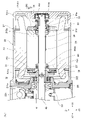
- FIG. 2 is a partial cross-sectional view showing an enlarged configuration of the vicinity of a motor portion (motor with a clutch) in FIG. 2.
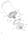
- FIG. 3 is an exploded perspective view showing the configurations of the rotor of the electric chain block shown in FIG. 1, the motor shaft, the clutch plate constituting the friction clutch, and the connecting member.
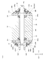
- It is sectional drawing which shows the structure of the friction clutch mechanism and the vicinity of a rotor which concerns on 2nd Embodiment.
- the electric chain block 10 including the motor unit 20 (motor with clutch) according to the first embodiment of the present invention will be described with reference to the drawings.
- the Z direction refers to the direction in which the chain C1 is suspended
- the Z1 side refers to the side on which the upper hook 90 is located
- the Z2 side is located on the opposite lower hook 100. Point to the side.
- the X direction refers to the longitudinal direction of the motor shaft 25, the X1 side refers to the right side in FIG. 2, and the X2 side refers to the opposite left side.
- the Y direction refers to a direction orthogonal to the Z direction and the X direction, the Y1 side refers to the lower right side in FIG. 1, and the Y2 side refers to the upper left side opposite to the right side.
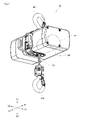
- FIG. 1 is a perspective view showing a configuration of an electric chain block 10 according to an embodiment of the present invention.
- FIG. 2 is a cross-sectional view showing a state in which the electric chain block 10 shown in FIG. 1 is cut by a plane for cutting the motor shaft 25.
- FIG. 3 is a partial cross-sectional view showing the configuration of the vicinity of the motor unit 20 (motor with a clutch) in FIG. 2 in an enlarged manner.
- the electric chain block 10 includes a motor unit 20, a drive transmission shaft 40, a deceleration mechanism 50, a load sheave 60, a brake mechanism 70, a control circuit 80, and an upper hook 90. And a lower hook 100.
- FIG. 4 is an exploded perspective view showing the configurations of the stator 23, the rotor 24, the motor shaft 25, and the drive transmission shaft 40 constituting the motor portion 20 of the electric chain block 10 shown in FIG.
- the motor unit 20 includes a motor casing 21, a motor 22, and a friction clutch mechanism 30.
- the motor casing 21 is a case that covers the motor 22 and protects the motor 22 from external impacts, dust, and the like.
- the motor casing 21 is provided with an end cover 21A1, and one side of the motor 22 in the axial direction (X direction) is covered by the end cover 21A1 (the second embodiment and the third embodiment described later). The same applies to the configuration in the form).
- the motor 22 includes a stator 23 and a rotor 24, and corresponds to, for example, a three-phase induction motor.
- the motor 22 is not limited to the three-phase induction motor, and other induction motors such as a single-phase induction motor may be used. It is also possible to use a motor other than the induction motor as the motor 22. Examples of other motors include synchronous motors and the like.
- the stator 23 is non-rotatably fixed to the inner peripheral surface of the motor casing 21. Further, the stator 23 has a stator core (reference numeral omitted) and a coil 231 formed by winding a conducting wire, and the coil 231 has a coil 231 in the axial direction (X direction) as shown in FIG. A cylindrical projecting portion 231a projecting from the end surface of the rotor 24 is formed.
- the rotor 24 has a laminated silicon steel plate, a conductor par made of an aluminum metal (both not shown), and end rings 241 arranged on both ends of the conductor bar. Further, an insertion hole 242 through which the motor shaft 25 is inserted is formed in the center of the rotor 24 in the radial direction. A clutch plate, which will be described later, is attached to the end ring 241.
- bearing mounting portions 242a having a diameter larger than that of the intermediate portion of the insertion hole 242 are provided on both ends of the insertion hole 242 of the rotor 24 in the axial direction (X direction).
- Bearings B1 and B2 are arranged on the bearing mounting portion 242a.
- the bearing B1 is arranged on one side in the axial direction (X direction), and the bearing B2 is arranged on the other side (X2 side) in the axial direction (X direction).
- These bearings B1 and B2 pivotally support the rotor 24 in a state where it can rotate with the motor shaft 25.
- the bearing mounting portion 242a is provided so as to have a smaller diameter toward the center position in the longitudinal direction (here, the axial direction (X direction)) of the rotor 24. Therefore, the bearing B1 arranged on the bearing mounting portion 242a on one side (X1 side) in the axial direction (X direction) is prevented from moving to the other side (X2 side) in the axial direction (X direction). There is.
- the motor shaft 25 uses a solid shaft member instead of a hollow shaft member.
- the motor shaft 25 is rotatably supported by the rotor 24 via the bearings B1 and B2 as described above, that is, the motor shaft 25 is supported by the rotor 24 if the friction clutch mechanism 30 described later does not exist. On the other hand, it can rotate freely.
- a spline 251 is provided on the outer periphery of the motor shaft 25 on the other end side (X2 side) in the axial direction.
- the spline 251 meshes with the spline groove 321a formed on the inner cylinder surface of the connecting member 32 of the friction clutch mechanism 30 described later.
- the motor shaft 25 and the connecting member 32 are press-fitted and fixed so that the axes coincide with each other. Therefore, the motor shaft 25 rotates integrally with the connecting member 32 without rotational runout.
- one end side (X1 side) of the drive transmission shaft 40 in the axial direction (X direction) is inserted into the connecting member 32.
- a spline 41 is provided on the outer periphery of the drive transmission shaft 40 on one end side (X1 side) in the axial direction (X direction) and meshes with the spline groove 321a of the connecting member 32. Therefore, the driving force of the motor shaft 25 is transmitted to the drive transmission shaft 40 via the connecting member 32.
- a gear portion 42 is provided in the middle portion of the drive transmission shaft 40, and the gear portion 42 meshes with the transmission gear (not shown) of the reduction mechanism 50. Then, the drive of the drive transmission shaft 40 is transmitted to the load sheave 60 via the deceleration mechanism 50.
- the load sheave 60 is provided with a plurality of chain pockets (reference numerals omitted), and the metal ring of the load chain C1 can be fitted into the chain pockets. Therefore, it is possible to wind up and down the load chain C1 by driving the motor 22.
- the electric chain block 10 includes a brake mechanism 70 and a control circuit 80.
- the brake mechanism 70 is a mechanism that is arranged on the other end side (X2 side) of the drive transmission shaft 40 and brakes the load sheave 60 to hold the load in a predetermined position.
- the control circuit 80 is a circuit for controlling the operation of the motor 22.
- the control circuit 80 includes a memory (not shown), and a program and data for executing desired control are stored in the memory.
- FIG. 5 is an exploded perspective view showing the configurations of the rotor 24 of the electric chain block shown in FIG. 1, the motor shaft 25, the clutch plate 31 constituting the friction clutch, and the connecting member 32.
- the friction clutch mechanism 30 includes a clutch plate 31, a connecting member 32, a spring member 33, and an adjusting member 34.
- the clutch plate 31 is a member for exerting a desired frictional force with the clutch receiver 322 of the connecting member 32.
- the clutch plate 31 is made of a predetermined friction material (for example, a woven friction material, a resin mold friction material, a sintered material obtained by sintering a material containing metal, etc.).
- This clutch plate 31 is attached to the above-mentioned end ring 241. That is, the end ring 241 has a flat surface 241a perpendicular to the rotation axis so as to be in close contact with the clutch plate 31 and the side surface, and a boss portion 241b that fits with the inner circumference of the clutch plate 31 is provided at the center thereof. Have. Further, on the outer peripheral side of the end ring 241 is provided with an arc-shaped protruding portion 241c that protrudes in the axial direction (X direction) from the flat surface 241a. The protruding portion 241c is fitted with the fitting portion 312 described later of the clutch plate 31 in the circumferential direction, and is fixed so as to rotate integrally with the clutch plate 31. In FIG.
- mounting recesses 241d notched at a predetermined pitch are formed between the four arc-shaped protrusions 241c.
- the mounting recess 241d is provided so as to be recessed from the flat surface 241a by a predetermined depth in the axial direction.
- the clutch plate 31 is provided with a ring-shaped portion 311 and a fitting portion 312 on the outer peripheral portion thereof.
- the fitting portion 312 is a protruding piece portion having a narrow width in the circumferential direction, but may be wide.
- the ring-shaped portion 311 is provided in a ring shape, and its surface (a surface facing the clutch receiver described later) is a sliding surface.
- the fitting portion (protruding piece portion) 312 is a portion protruding from the ring-shaped portion 311 toward the outer diameter side, and is fitted with the above-mentioned protruding portion 241c in the circumferential direction to serve as a detenting means for the clutch plate 31. It has become.
- the protruding portion 241c has an arc shape (fan shape), but it does not have to have an arc shape, and can be fitted to the outer peripheral portion of the clutch plate 31 to prevent rotation in the rotation direction of the rotor 24. Any shape may be used as long as it is a locking shape.
- the connecting member 32 is provided with a tubular portion 321 and a clutch receiver 322.
- the tubular portion 321 is a portion provided in a tubular shape.
- a spline groove 321a is provided on the inner tubular surface of the tubular portion 321, and the spline groove 321a meshes with the spline 251 of the motor shaft 25 and the spline 41 of the drive transmission shaft 40 described above.
- the outer diameter of the spline 251 of the motor shaft 25 is slightly larger than the outer diameter of the spline 41 of the drive transmission shaft 40, and the clutch receiver 322 and the motor shaft 25 are coaxially press-fitted and fixed to each other.
- the bearing B3 is attached to the other side (X2 side) of the tubular portion 321 in the axial direction (X direction).
- the bearing B3 is attached to the bearing mounting portion 211a of the motor casing 21.
- the bearing B4 is also attached to one end side (X1 side) of the motor shaft 25 in the axial direction (X direction) described above, and the bearing B4 is attached to the bearing mounting portion 211b of the motor casing 21.
- the motor shaft 25 is rotatably and freely supported with respect to the motor casing 21 to which the stator 23 is fixed without shaft deviation.
- the bearing B3 is provided with a larger diameter than the bearing B4.
- the tubular portion 321 is integrally provided with a clutch receiver 322. That is, the clutch receiver 322 integrated with the tubular portion 321 projects from the outer peripheral surface of the tubular portion 321 toward the outer diameter side. So to speak, in the connecting member 32, the clutch receiver 322 is provided in a flange shape. The clutch receiver 322 is a portion that comes into contact with the sliding surface of the clutch plate 31 while applying a predetermined frictional force. When a load below the specified value acts on the drive transmission shaft 40 and the connecting member 32 via the load sheave 60, the clutch plate 31 and the clutch receiver 322 respond to the pressing force from the spring member 33, which will be described later. Due to the frictional force between them, the clutch receiver 322 follows the rotation of the clutch plate 31.
- the clutch plate 31 and the clutch receiver 322 of the connecting member 32 are arranged in the portion of the stator 23 surrounded by the cylindrical protruding portion 231a (the inner cylinder side of the protruding portion 231a). Therefore, compared with the configuration in which the clutch plate 31 and the connecting member 32 are arranged on the outside of the protruding portion 231a (the portion protruding from the inner cylinder side of the protruding portion 231a to the other side (X2 side) in the axial direction (X direction)). Therefore, the inner cylinder side of the protruding portion 231a, which is a dead space, can be effectively used, and the total length of the motor portion 20 in the axial direction (X direction) can be shortened.
- the clutch receiver 322 is in a state of being in parallel contact with the clutch plate 31.
- the clutch receiver 322 does not abut in parallel with the clutch plate 31 due to the tubular portion 321 and the clutch receiver 322 being separate bodies or the like, the clutch receiver 322 is pushed diagonally by the clutch plate 31. It becomes. In that case, the rotation stability of the connecting member 32 is lost, and the motor portion 20 and other parts may vibrate due to the connecting member 32.
- the tubular portion 321 and the clutch receiver 322 are integrated, it is possible to prevent such vibration from occurring.
- a spring member 33 is arranged on one side (X1 side) in the axial direction (X direction) in a state adjacent to the bearing B1.
- the spring member 33 corresponds to the urging means.
- the spring member 33 is configured by stacking a plurality of disc springs 33a in the axial direction (X direction).
- the adjusting member 34 is arranged on one side (X1 side) in the axial direction (X direction) of the spring member 33.
- the adjusting member 34 is a nut in the present embodiment, and can be screwed into a male screw portion (reference numeral omitted) formed on one end side of the motor shaft 25.
- a washer Z1 for preventing rotation of the adjusting member 34 and a spacer S1 for the hollow shaft are arranged between the adjusting member 34 and the spring member 33, and adjustment is performed via the washer Z1 and the spacer S1 for the hollow shaft.
- the member 34 presses the spring member 33.
- the connecting member 32 is press-fitted and fixed to the motor shaft 25 to be integrated with the motor shaft 25.
- the clutch receiver 322 of the connecting member 32 can receive the pressing force of the spring member 33.
- the spring member 33 causes the inner race of the bearing B1 to be screwed to the other side (X2 side) as the screwing progresses. ), And the rotor 24 and the clutch plate 31 are gradually and strongly pressed toward the other side (X2 side) in the axial direction (X direction) via the bearing B1. That is, it is possible to easily perform the urging force of the spring member 33 by adjusting the degree of screwing of the adjusting member 34 after assembling the motor 22 and before attaching the motor casing 21. By adjusting the urging force, the frictional force between the clutch plate 31 and the clutch receiver 322 can be adjusted. In this way, the frictional force between the clutch plate 31 and the clutch receiver 322 can be adjusted before being incorporated into the inner peripheral portion of the stator 23.
- the clutch receiving 322 is a clutch plate by pressing the spring member 33 (the urging means). The frictional force between the 31 and the clutch receiver 322 cannot be followed, and the clutch plate 31 (rotor 24) runs idle with respect to the clutch receiver 322 (connecting member 32).
- the electric chain block 10 includes an upper hook 90 and a lower hook 100 in addition to the above configuration.
- the upper hook 90 is a portion to be hung on a predetermined portion such as a ceiling.
- the lower hook 100 is a portion to be hung on a load or the like, and is connected to an end portion of the chain C1. Then, the electric chain block 10 can raise and lower the load by winding or lowering the chain C1 with the load hooked on the lower hook 100.
- the direction of the electric chain block 10 may be turned upside down, and the lower hook 100 may be hung on a predetermined portion such as the ceiling to load the upper hook 90.
- the electric chain block 10 moves up and down, and the load also moves up and down as the chain C1 moves up and down.
- the stator 23 is capable of generating a rotating magnetic field by passing a current through the coil 231 and is arranged in the inner cylinder portion of the stator 23 to generate a rotating magnetic field.
- the rotor 24 rotated by the rotor 24, the motor shaft 25 that is rotatable with respect to the rotor 24 via bearings (bearings B1 and B2) while inserting the radial center of the rotor 24, and the motor shaft of the rotor 24.
- a friction clutch mechanism 30 arranged on the end side in the axial direction (X direction) of the 25 is provided.
- the friction clutch mechanism 30 has a clutch plate 31 that rotates integrally with the rotor 24 by being fixed to the end face side of the motor shaft 25 in the axial direction (X direction) of the rotor 24, and a tubular portion 321. Then, on the connecting member 32 in which the motor shaft 25 and the drive transmission shaft 40 are inserted into the inner cylinder portion of the tubular portion 321 in a state of being integrally rotated with the tubular portion 321, and on the outer peripheral side of the connecting member 32. It has a clutch receiver 322 that is arranged and rotates integrally with the connection member 32, and a spring member 33 (urging means) that urges the clutch plate 31 and the clutch receiver 322 in a direction to bring them into contact with each other. There is.
- the clutch receiver 322 is arranged on the outer peripheral side of the connecting member 32. Therefore, as compared with the configuration disclosed in Patent Document 1, the connecting member and the clutch receiver are separately and independently arranged in the axial direction (X direction) of the motor shaft 25, as compared with the configuration of the motor shaft 25.
- the length in the axial direction (X direction) can be shortened to reduce the size of the motor unit 20 (motor with clutch).
- the motor shaft 25 is larger than the cylindrical portion 321 of the connecting member 32. It is a solid shaft with a small diameter. Therefore, it is possible to prevent the motor unit 20 (motor with a clutch) from becoming larger in the radial direction. Further, the vibration when the friction clutch mechanism 30 is activated is generated by the bearing B3 having a larger diameter than the bearing B4 bearing one end side of the motor shaft 25, and the tubular portion 321 of the connecting member 32 having the clutch receiver 322. Since it is directly bearing, the bearing life is improved and the friction performance is stable.
- the clutch receiver 322 is provided in a flange shape and is integrally formed with a cylindrical portion.
- the clutch receiver 322 is oriented in a direction orthogonal to the axial direction (X direction) over the entire circumference in the circumferential direction. Protrude. Therefore, the clutch receiver 322 is in contact with the clutch plate 31 in parallel over the entire circumference in the circumferential direction.
- the clutch receiver 322 is pushed diagonally by the clutch plate 31. It becomes. In that case, the rotation stability of the connecting member 32 is lost, and the motor portion 20 and other parts may vibrate due to the connecting member 32.
- the tubular portion 321 and the clutch receiver 322 are integrally formed. Therefore, it is possible to prevent the above-mentioned vibration from occurring.
- the electric chain block 10 of the present embodiment includes a motor unit 20 (motor with a clutch), and also has a drive transmission shaft 40 that is arranged coaxially with the motor shaft 25 and rotates integrally with the motor shaft 25. It includes a deceleration mechanism 50 that decelerates rotation from the drive transmission shaft 40, and a load sheave 60 in which a drive force is transmitted via the deceleration mechanism 50 and a chain C1 is wound around.
- the connecting member and the clutch receiver are separately and independently arranged in the axial direction (X direction) of the motor shaft 25, as compared with the configuration.
- the axial length (X direction) of the motor shaft 25 can be shortened to reduce the size of the motor unit 20 (motor with clutch). Therefore, the dimension of the electric chain block 10 in the axial direction (X direction) can be reduced, and the size of the electric chain block 10 can be reduced accordingly.
- the motor shaft 25 is larger than the cylindrical portion 321 of the connecting member 32. It is a solid shaft with a small diameter. Therefore, it is possible to prevent the motor unit 20 (motor with a clutch) from becoming larger in the radial direction. Further, the vibration when the friction clutch mechanism 30 is activated is generated by the bearing B3 having a larger diameter than the bearing B4 bearing one end side of the motor shaft 25, and the tubular portion 321 of the connecting member 32 having the clutch receiver 322. Since the bearing is directly bearing, the bearing life is improved and the friction performance can be stabilized. Therefore, it is possible to prevent the electric chain block 10 from increasing in size in a direction orthogonal to the axial direction (X direction), and it is possible to exhibit stable performance with a long life.
- the electric chain block 10 including the motor unit 20 (motor with clutch) according to the second embodiment of the present invention will be described.
- the motor unit 20 (motor with clutch) of the present embodiment has the same configuration as the motor unit 20 of the first embodiment. Therefore, in the following description, the parts common to the first embodiment will be described using the same reference numerals.
- FIG. 6 is a cross-sectional view showing a configuration in the vicinity of the friction clutch mechanism 30B and the rotor 24 according to the second embodiment.
- the configuration of the friction clutch mechanism 30 is different from that of the friction clutch mechanism 30 according to the first embodiment described above.
- the friction clutch mechanism 30 according to the second embodiment will be referred to as a friction clutch mechanism 30B, and the original configuration of the friction clutch mechanism 30B will be described by adding the alphabet "B" after the reference numerals. ..
- the friction clutch mechanism 30B is provided with a first friction clutch mechanism 30B1 and a second friction clutch mechanism 30B2.
- the adjusting member 34 and the washer Z1 also exist as a configuration common to the first friction clutch mechanism 30B1 and the second friction clutch mechanism 30B2. These will be described in detail below.
- the first friction clutch mechanism 30B1 is arranged on the other side (X2 side) of the rotor 24 in the axial direction (X direction).
- the first friction clutch mechanism 30B1 has the same clutch plate 31 as in the first embodiment, a connecting member 32B, a clutch receiver 322B, a spring receiver 35B, and a spring member 36B.
- the connecting member 32B has a cylindrical portion 321B having a shape different from that of the above-mentioned tubular portion 321.
- the tubular portion 321B is not integrally provided with a portion similar to the clutch receiver 322. That is, the clutch receiver 322B is provided separately from the connecting member 32B.
- the connecting member 32B is provided with a large diameter portion 323B formed to have a larger diameter than the other side in the axial direction (X direction).
- a clutch receiver 322B which is separate from the connecting member 32B, is arranged on the outer peripheral side of the large diameter portion 323B. Therefore, although the clutch receiver 322B is provided in a ring shape, the clutch receiver 322B is spline-coupled to the outer peripheral surface of the connection member 32B so that the clutch receiver 322B does not rotate with respect to the connection member 32B.
- the pin member 39B which will be described later, is connected to the pin member 39B using the same pin member as the pin member 39B.
- a locking projection 324B is provided on the other end side (X2 side) of the large diameter portion 323B in the axial direction (X direction), and the locking projection 324B is located on the outer diameter side of the large diameter portion 323B. It protrudes toward you.
- a ring-shaped spring receiver 35B is arranged on the locking projection 324B.
- a spring member 36B is arranged between the spring receiver 35B and the clutch receiver 322B.
- the spring member 36B presses the clutch plate 31 toward the clutch receiver 322B via the second friction clutch mechanism 30B2 and the rotor 24 by tightening the adjusting member 34, and the spring member 36B presses the clutch plate 31 together with the spring member 33. Is received and transmitted in an adjustable manner.
- the spring member 36B is configured by stacking a plurality of disc springs 33Ba in the axial direction (X direction), similarly to the spring member 33.
- the second friction clutch mechanism 30B2 is arranged on one side (X1 side) of the rotor 24 in the axial direction (X direction).
- the second friction clutch mechanism 30B2 has a clutch plate 37B, a clutch receiver 38B, and a spring member 33.
- the clutch plate 37B is fixed to the end ring 241 on one side (X1 side) in the axial direction (X direction). Further, in the clutch receiver 38B that abuts on one side (X1 side) surface of the clutch plate 37B, the one side (X1 side) surface of the clutch receiver 38B is pressed by the spring member 33, and the pressing by the spring member 33 causes the clutch receiver 38B to be pressed. A predetermined frictional force is generated between the clutch receiver 38B and the clutch plate 37B.
- the motor shaft 25 is formed with a pin hole 25a for inserting the pin member 39B so as to penetrate along the radial direction.
- the pin member 39B inserted into the pin hole 25a is also inserted into the pin insertion hole 38Ba of the clutch receiver 38B described above.
- the pin insertion hole 38Ba is a narrow hole portion formed along the radial direction, similarly to the pin hole 25a described above.
- the pin insertion hole 38Ba penetrates the clutch receiver 38B in the axial direction (X direction). Therefore, the clutch receiver 38B can move in the axial direction (X direction) due to the fluctuation of the pressing state by the spring member 33. However, the movement of the clutch receiver 38B in the rotational direction is prevented by the pin member 39B.
- the two friction clutch mechanisms the first friction clutch mechanism 30B1 and the second friction clutch mechanism 30B2
- the two friction clutch mechanisms can be used, so that the life of the friction clutch mechanism 30B can be extended. It will be possible. Further, since two friction clutch mechanisms can be used, it is possible to increase the value of the load torque transmitted even if the rotor 24 has a small diameter. Further, since the pressing force acting between the clutch plate 31 and the clutch receiver 322B does not act on the bearings B1 and B2, it is possible to increase the tightening by the adjusting member 34, and the electric chain block 10 using a high torque motor can be used. The friction clutch mechanism 30B can be applied.
- the clutch receiver 322B is provided in a ring shape separate from the connecting member 32B, and the clutch receiver 322B is coupled in a state of being integrally rotated with respect to the outer peripheral surface of the connecting member 32B. ing.
- the clutch receiver 322B can be moved in the axial direction (X direction) independently of the connecting member 32B, the spring member 36B is arranged on the outer peripheral side of the connecting member 32B as shown in FIG. It becomes possible to do.
- the axial direction (X direction) of the motor shaft 25 is compared with the configuration in which the connecting member and the clutch receiver are separately and independently arranged in the axial direction (X direction) of the motor shaft 25.
- the length can be shortened to reduce the size of the motor unit 20 (motor with clutch).
- the motor shaft 25 is larger than the cylindrical portion 321B of the connecting member 32B. It is a solid shaft with a small diameter. Therefore, it is possible to prevent the motor unit 20 (motor with a clutch) from becoming larger in the radial direction. Further, the vibration when the friction clutch mechanism 30 is activated is generated by the bearing B3 having a larger diameter than the bearing B4 bearing one end side of the motor shaft 25, and the tubular portion 321 of the connecting member 32 having the clutch receiver 322. Since it is directly bearing, the bearing life is improved and the friction performance is stable.
- the electric chain block 10 including the motor unit 20 (motor with clutch) according to the third embodiment of the present invention will be described.
- the motor unit 20 (motor with clutch) of the present embodiment has the same configuration as the motor unit 20 of the first embodiment. Therefore, in the following description, the parts common to the first embodiment will be described using the same reference numerals.
- the configuration of the friction clutch mechanism 30 is different from the friction clutch mechanism 30 according to the first embodiment and the friction clutch mechanism 30B according to the second embodiment described above.
- the friction clutch mechanism 30 according to the third embodiment will be referred to as a friction clutch mechanism 30C, and the original configuration of the friction clutch mechanism 30C will be described by adding the alphabet "C" after the reference numerals. ..
- FIG. 7 is a cross-sectional view showing the configuration of the motor unit 20 having the friction clutch mechanism 30C according to the third embodiment.
- the shaft hole 21C2 is formed in the end cover 21C1 in the axial direction (X direction) of the motor casing 21C.
- a bearing B4 is arranged in the shaft hole 21C2, and the motor shaft 25C extends toward the outside of the shaft hole 21C2 from the bearing B4.
- a male screw portion (not shown) is formed at the tip of the extending portion, and the adjusting member 34C is screwed into the male screw portion.
- a disc spring 33Ca constituting the spring member 33C is arranged between the adjusting member 34C and the bearing B4, and the inner race of the spring member 33C and the bearing B4 is pressed by screwing the adjusting member 34C.
- a hollow shaft-shaped spacer S1C is arranged between the bearing B4 and the bearing B1, and the pressing force is transmitted to the rotor 24 via both inner races. Therefore, the motor shaft 25C is provided with the same or longer length in the axial direction (X direction) than the motor shaft 25 of the first embodiment and the second embodiment.
- the tip side of the motor shaft 25C in the axial direction (X direction) is located outside the motor casing 21C, but a resin cap 21C3 is arranged on the tip side thereof, and the inside of the motor casing 21C.
- the shaft hole 21C2 is sealed so as to prevent dust and rainwater from entering one end of the motor shaft 25C, the adjusting member 34C, the spring member, and the like.
- a wave washer ZW for the bearing is arranged together with the bearing B3 on the bearing mounting portion 211a of the motor casing 21C to absorb the thickness fluctuation due to the wear of the clutch plate 31 and prevent the motor shaft 25 from rattling.
- the tip end side of the motor shaft 25C is located in the shaft hole 21C2 of the motor casing 21C, and the male screw portion of the motor shaft 25C located in the shaft hole 21C2 has a spring member.
- the adjusting member 34C for adjusting the urging force of 33C (the urging means) is screwed in.
- the adjusting member 34C is arranged outside the motor casing 21C, it is possible to screw in the adjusting member 34C which is a nut without disassembling the motor casing 21C. Therefore, by simply adjusting the screwing amount (screw torque) of the adjusting member 34C, the degree of screwing of the adjusting member 34 is adjusted after the motor 22 is assembled and before the motor casing 21 is attached. , It is possible to easily perform the urging force of the spring member 33C. Therefore, it is possible to adjust the frictional force of the friction clutch mechanism 30C by adjusting the urging force.
- friction clutch mechanism 30C can produce the same action and effect as the friction clutch mechanism 30 of the first embodiment described above.
- the same friction clutch mechanism 30B as described in the above-mentioned second embodiment may be used. That is, in the friction clutch mechanism 30C, the same first friction clutch mechanism as the first friction clutch mechanism 30B1 may be used, and the second friction clutch mechanism similar to the second friction clutch mechanism 30B2 may be used.
- one end side of the motor shaft 25C shown in FIG. 7 may be further extended so as to protrude from the end cover 21C1 to one side in the axial direction (X direction), and a cooling fan may be attached.
- 10 Electric chain block, 20 ... Motor part (corresponding to a motor with a clutch) 21,21C ... Motor casing, 21A1,21C1 ... End cover, 21C2 ... Shaft hole, 21C3 ... Resin cap, 22 ... Motor, 23 ... Stator , 24 ... rotor, 25, 25C ... motor shaft, 25a ... pin hole, 30, 30B, 30C ... friction clutch mechanism, 30B1 ... first friction clutch mechanism, 30B2 ... second friction clutch mechanism, 31, 37B ... clutch plate, 32, 32B ... Connection member, 33, 33C ... Spring member (corresponding to urging means), 33a, 33Ba ... Flat spring, 34, 34C ... Adjustment member, 35B ... Spring receiver, 36B ...
- Bearing mounting part 251 ... Spline, 311 ... Ring-shaped part, 312 ... Fitting part (protruding piece part), 321, 321B ... Cylindrical part, 321a ... Spline groove, 322 , 322B ... Clutch receiver, 323B ... Large diameter part, 324B ... Locking protrusion, B1-B4 ... Bearing, C1 ... Chain, S1, S1C ... Spacer, Z1 ... Seat, ZW ... Wave washer
Landscapes
- Engineering & Computer Science (AREA)
- Power Engineering (AREA)
- Mechanical Engineering (AREA)
- General Engineering & Computer Science (AREA)
- Connection Of Motors, Electrical Generators, Mechanical Devices, And The Like (AREA)
Abstract
Description
以下、本発明の第1の実施の形態に係る、モータ部20(クラッチ付きモータ)を備える電気チェーンブロック10について、図面を参照しながら説明する。なお、以下の説明においては、Z方向とは、チェーンC1を吊り下げる方向を指し、Z1側とは上フック90が位置する側を指し、Z2側とはそれとは逆の下フック100が位置する側を指す。
図1は、本発明の一実施の形態に係る電気チェーンブロック10の構成を示す斜視図である。図2は、図1に示す電気チェーンブロック10を、モータ軸25を切断する平面で切断した状態を示す断面図である。図3は、図2のうちモータ部20(クラッチ付きモータ)付近の構成を拡大して示す部分的な断面図である。図1から図3に示すように、電気チェーンブロック10は、モータ部20と、駆動伝達軸40と、減速機構50と、ロードシーブ60と、ブレーキ機構70と、制御回路80と、上フック90と、下フック100とを有している。
次に、フリクションクラッチ機構30について説明する。図5は、図1に示す電気チェーンブロックのロータ24と、モータ軸25と、フリクションクラッチを構成するクラッチ板31および接続部材32の構成を示す分解斜視図である。図2から図5に示すように、フリクションクラッチ機構30は、クラッチ板31と、接続部材32と、ばね部材33と、調整部材34とを有している。これらのうち、クラッチ板31は、接続部材32のクラッチ受け322との間で所望の摩擦力を及ぼすための部材である。このクラッチ板31は、所定の摩擦材(たとえばウーブン系の摩擦材、レジンモールド系の摩擦材、金属を含む材料を焼結した焼結材等)を材質としている。
以上のような構成のモータ部20(クラッチ付きモータ)においては、コイル231に電流を流すことで回転磁界を生じさせることが可能なステータ23と、ステータ23の内筒部に配置され、回転磁界によって回転させられるロータ24と、ロータ24の径方向の中心を挿通していると共に、ロータ24に対し軸受(ベアリングB1,B2)を介して回転可能なモータ軸25と、ロータ24のうちモータ軸25の軸方向(X方向)の端部側に配置されるフリクションクラッチ機構30と、を備える。そして、フリクションクラッチ機構30は、ロータ24のうちモータ軸25の軸方向(X方向)の端面側に固定されることでロータ24と一体的に回転するクラッチ板31と、筒状部321を有し、この筒状部321の内筒部にモータ軸25と駆動伝達軸40とが当該筒状部321と一体的に回転する状態で挿入される接続部材32と、接続部材32の外周側に配置され、当該接続部材32と一体的に回転するクラッチ受け322と、クラッチ板31とクラッチ受け322とを互いに当接させる向きに付勢するばね部材33(付勢手段)と、を有している。
以下、本発明の第2の実施の形態に係る、モータ部20(クラッチ付きモータ)を備える電気チェーンブロック10について説明する。なお、本実施の形態のモータ部20(クラッチ付きモータ)は、第1の実施の形態に係るモータ部20と同様の構成となっている。したがって、以下の説明では、第1の実施の形態と共通する部分については、同一の符号を用いて説明する。
以下、本発明の第3の実施の形態に係る、モータ部20(クラッチ付きモータ)を備える電気チェーンブロック10について説明する。なお、本実施の形態のモータ部20(クラッチ付きモータ)は、第1の実施の形態に係るモータ部20と同様の構成となっている。したがって、以下の説明では、第1の実施の形態と共通する部分については、同一の符号を用いて説明する。
以上、本発明の一実施の形態について説明したが、本発明はこれ以外にも変形可能となっている。以下、それについて述べる。
Claims (5)
- 駆動伝達軸に駆動力を伝達するクラッチ付きモータであって、
コイルに電流を流すことで回転磁界を生じさせることが可能なステータと、
前記ステータの内筒部に配置され、前記回転磁界によって回転させられるロータと、
前記ロータの径方向の中心を挿通していると共に、前記ロータに対し軸受を介して回転可能なモータ軸と、
前記ロータのうち前記モータ軸の軸方向の端部側に配置されるフリクションクラッチ機構と、
を備え、
前記フリクションクラッチ機構は、
前記ロータのうち前記モータ軸の軸方向の端面側に固定されることで前記ロータと一体的に回転するクラッチ板と、
筒状部を有し、この筒状部の内筒部に前記モータ軸と前記駆動伝達軸とが当該筒状部と一体的に回転する状態で挿入される接続部材と、
前記接続部材の外周側に配置され、当該接続部材と一体的に回転するクラッチ受けと、
前記クラッチ板と前記クラッチ受けとを互いに当接させる向きに付勢する付勢手段と、
を有することを特徴とするクラッチ付きモータ。 - 請求項1記載のクラッチ付きモータであって、
前記クラッチ受けは、フランジ状に設けられていると共に前記筒状部と一体形成されている、
ことを特徴とするクラッチ付きモータ。 - 請求項1記載のクラッチ付きモータであって、
前記クラッチ受けは前記接続部材とは別体のリング状に設けられていて、
前記クラッチ受けは、前記接続部材の外周面に対して一体回転する状態で結合されている、
ことを特徴とするクラッチ付きモータ。 - 請求項1から3のいずれか1項に記載のクラッチ付きモータであって、
前記モータ軸の先端側は、前記ステータおよび前記ロータを収納するモータケーシングの軸孔に位置していると共に、当該軸孔に位置する前記モータ軸の先端側の雄ネジ部には、前記付勢手段の付勢力を調整する調整部材が捻じ込まれている、
ことを特徴とするクラッチ付きモータ。 - 請求項1から4のいずれか1項に記載のクラッチ付きモータを備えると共に、
前記モータ軸と同軸上に配置されて当該モータ軸と一体的に回転する前記駆動伝達軸を備え、
前記駆動伝達軸からの回転を減速する減速機構と、
前記減速機構を介して駆動力が伝達されると共にチェーンが巻回されるロードシーブと、
を備えることを特徴とする電気チェーンブロック。
Priority Applications (4)
| Application Number | Priority Date | Filing Date | Title |
|---|---|---|---|
| CN202180069029.3A CN116323467A (zh) | 2020-10-22 | 2021-10-18 | 带离合器的电动机及电动链式葫芦 |
| JP2022557522A JP7451024B2 (ja) | 2020-10-22 | 2021-10-18 | クラッチ付きモータおよび電気チェーンブロック |
| US18/032,190 US12483092B2 (en) | 2020-10-22 | 2021-10-18 | Clutch-equipped motor and electric chain block |
| DE112021005556.9T DE112021005556T5 (de) | 2020-10-22 | 2021-10-18 | Mit kupplung ausgerüsteter motor und elektrisch betriebener kettenflaschenzug |
Applications Claiming Priority (2)
| Application Number | Priority Date | Filing Date | Title |
|---|---|---|---|
| JP2020177449 | 2020-10-22 | ||
| JP2020-177449 | 2020-10-22 |
Publications (1)
| Publication Number | Publication Date |
|---|---|
| WO2022085629A1 true WO2022085629A1 (ja) | 2022-04-28 |
Family
ID=81290759
Family Applications (1)
| Application Number | Title | Priority Date | Filing Date |
|---|---|---|---|
| PCT/JP2021/038442 Ceased WO2022085629A1 (ja) | 2020-10-22 | 2021-10-18 | クラッチ付きモータおよび電気チェーンブロック |
Country Status (6)
| Country | Link |
|---|---|
| US (1) | US12483092B2 (ja) |
| JP (1) | JP7451024B2 (ja) |
| CN (1) | CN116323467A (ja) |
| DE (1) | DE112021005556T5 (ja) |
| TW (1) | TW202218293A (ja) |
| WO (1) | WO2022085629A1 (ja) |
Families Citing this family (1)
| Publication number | Priority date | Publication date | Assignee | Title |
|---|---|---|---|---|
| WO2025203693A1 (ja) * | 2024-03-29 | 2025-10-02 | 株式会社キトー | バッテリ搭載式の電気チェーンブロック |
Citations (8)
| Publication number | Priority date | Publication date | Assignee | Title |
|---|---|---|---|---|
| JPS5342937B2 (ja) * | 1972-10-13 | 1978-11-15 | ||
| JPS5411582B2 (ja) * | 1972-12-30 | 1979-05-16 | ||
| US4460838A (en) * | 1982-08-06 | 1984-07-17 | Ecm Motor Co. | Electric motor with braking arrangement |
| US20080041651A1 (en) * | 2006-08-18 | 2008-02-21 | Kevin Wei-Loong Ng | Clutch device for seatbelt retractor |
| JP2009079635A (ja) * | 2007-09-25 | 2009-04-16 | Kito Corp | 湿式摩擦板 |
| JP2013184790A (ja) * | 2012-03-08 | 2013-09-19 | Kito Corp | 手動巻上牽引装置 |
| JP2015053839A (ja) * | 2013-09-09 | 2015-03-19 | 株式会社キトー | ブレーキモータ |
| JP2018173033A (ja) * | 2017-03-31 | 2018-11-08 | 株式会社 神崎高級工機製作所 | エンジン始動発電ユニット及び油圧回路 |
Family Cites Families (12)
| Publication number | Priority date | Publication date | Assignee | Title |
|---|---|---|---|---|
| US2373007A (en) * | 1941-11-03 | 1945-04-03 | Asea Electric Ltd | Hoist, crane, lift, and the like lifting apparatus |
| JPS5939692A (ja) * | 1982-08-25 | 1984-03-05 | 株式会社キト− | 電気式巻上兼牽引装置 |
| JPS5939695A (ja) * | 1982-08-25 | 1984-03-05 | 株式会社キト− | 巻上兼牽引装置 |
| US4636962A (en) * | 1983-05-24 | 1987-01-13 | Columbus Mckinnon Corporation | Microprocessor-controlled hoist system |
| AU570695B2 (en) * | 1984-09-21 | 1988-03-24 | Columbus Mckinnon Corporation | Microprocessor-controlled hoist system |
| US5081385A (en) * | 1990-07-25 | 1992-01-14 | Gajjar Bhupendra M | Polyphase motor with adjustable clutch for smooth start |
| US5533712A (en) * | 1992-12-18 | 1996-07-09 | Elephant Chain Block Company Limited | Electric hoist and traction apparatus |
| DE4408578C2 (de) | 1994-03-14 | 1999-12-30 | Stahl R Foerdertech Gmbh | Sicherheitskupplung für einen Kettenzug |
| DE10244865B4 (de) * | 2002-09-23 | 2004-09-30 | Demag Cranes & Components Gmbh | Kettenzug |
| DE102006001154B4 (de) * | 2006-01-06 | 2009-01-22 | Yale Industrial Products Gmbh | Elektrisches Hebezeug |
| DE102009053613A1 (de) * | 2009-11-17 | 2011-05-19 | Demag Cranes & Components Gmbh | Kettenzug mit einer Rutschkupplung |
| CN108675184A (zh) * | 2018-08-13 | 2018-10-19 | 重庆维大力起重设备有限公司 | 一种紧凑型环链电葫芦 |
-
2021
- 2021-10-18 US US18/032,190 patent/US12483092B2/en active Active
- 2021-10-18 JP JP2022557522A patent/JP7451024B2/ja active Active
- 2021-10-18 WO PCT/JP2021/038442 patent/WO2022085629A1/ja not_active Ceased
- 2021-10-18 CN CN202180069029.3A patent/CN116323467A/zh active Pending
- 2021-10-18 DE DE112021005556.9T patent/DE112021005556T5/de active Pending
- 2021-10-22 TW TW110139230A patent/TW202218293A/zh unknown
Patent Citations (8)
| Publication number | Priority date | Publication date | Assignee | Title |
|---|---|---|---|---|
| JPS5342937B2 (ja) * | 1972-10-13 | 1978-11-15 | ||
| JPS5411582B2 (ja) * | 1972-12-30 | 1979-05-16 | ||
| US4460838A (en) * | 1982-08-06 | 1984-07-17 | Ecm Motor Co. | Electric motor with braking arrangement |
| US20080041651A1 (en) * | 2006-08-18 | 2008-02-21 | Kevin Wei-Loong Ng | Clutch device for seatbelt retractor |
| JP2009079635A (ja) * | 2007-09-25 | 2009-04-16 | Kito Corp | 湿式摩擦板 |
| JP2013184790A (ja) * | 2012-03-08 | 2013-09-19 | Kito Corp | 手動巻上牽引装置 |
| JP2015053839A (ja) * | 2013-09-09 | 2015-03-19 | 株式会社キトー | ブレーキモータ |
| JP2018173033A (ja) * | 2017-03-31 | 2018-11-08 | 株式会社 神崎高級工機製作所 | エンジン始動発電ユニット及び油圧回路 |
Also Published As
| Publication number | Publication date |
|---|---|
| TW202218293A (zh) | 2022-05-01 |
| DE112021005556T5 (de) | 2023-09-07 |
| JP7451024B2 (ja) | 2024-03-18 |
| JPWO2022085629A1 (ja) | 2022-04-28 |
| US12483092B2 (en) | 2025-11-25 |
| US20230396127A1 (en) | 2023-12-07 |
| CN116323467A (zh) | 2023-06-23 |
Similar Documents
| Publication | Publication Date | Title |
|---|---|---|
| US9653981B2 (en) | Linear actuator | |
| US20090039727A1 (en) | Motor and electric power steering apparatus | |
| KR101967648B1 (ko) | 전동기의 로터 조립체 | |
| JPH11122886A (ja) | 回転電機 | |
| JP7451024B2 (ja) | クラッチ付きモータおよび電気チェーンブロック | |
| JP2005054845A (ja) | ロックアップ装置のダンパー機構 | |
| KR101899799B1 (ko) | 모터 | |
| US20020047407A1 (en) | Motor having worm and worm wheel | |
| JP4604565B2 (ja) | 回転子、およびこれを備えた回転電機 | |
| KR102686934B1 (ko) | 전동모터 | |
| JP5967005B2 (ja) | 電動アクチュエータ | |
| US20070194666A1 (en) | Motor for electric power steering apparatus and method of manufacturing dynamic damper | |
| JP6381745B1 (ja) | 回転角度検出装置、および回転角度検出装置を備えた車両用駆動モータ | |
| JP2002303333A (ja) | 結合遮断装置 | |
| JP6878394B2 (ja) | コイルばねを利用したフリータイプ双方向クラッチ | |
| JP7256453B2 (ja) | 回転電機 | |
| JP3696788B2 (ja) | モータ | |
| JP4525046B2 (ja) | 電磁ボールクラッチ | |
| JP2021048660A (ja) | モータ及び圧入部材の組み付け方法 | |
| JP2005299742A (ja) | スプリングカップリング | |
| JP2006234116A (ja) | プーリ | |
| KR102796751B1 (ko) | 로터 및 이를 구비한 전동기 | |
| JP2007110776A (ja) | 回転電機 | |
| RU2249293C1 (ru) | Торцовая электрическая асинхронная машина | |
| JP2013165580A (ja) | 発電機 |
Legal Events
| Date | Code | Title | Description |
|---|---|---|---|
| 121 | Ep: the epo has been informed by wipo that ep was designated in this application |
Ref document number: 21882770 Country of ref document: EP Kind code of ref document: A1 |
|
| ENP | Entry into the national phase |
Ref document number: 2022557522 Country of ref document: JP Kind code of ref document: A |
|
| WWE | Wipo information: entry into national phase |
Ref document number: 112021005556 Country of ref document: DE |
|
| 122 | Ep: pct application non-entry in european phase |
Ref document number: 21882770 Country of ref document: EP Kind code of ref document: A1 |
|
| WWG | Wipo information: grant in national office |
Ref document number: 18032190 Country of ref document: US |