WO2022085655A1 - Pale d'éolienne, dispositif de surveillance de pale d'éolienne, dispositif de production d'énergie éolienne et procédé de surveillance de pale d'éolienne - Google Patents
Pale d'éolienne, dispositif de surveillance de pale d'éolienne, dispositif de production d'énergie éolienne et procédé de surveillance de pale d'éolienne Download PDFInfo
- Publication number
- WO2022085655A1 WO2022085655A1 PCT/JP2021/038514 JP2021038514W WO2022085655A1 WO 2022085655 A1 WO2022085655 A1 WO 2022085655A1 JP 2021038514 W JP2021038514 W JP 2021038514W WO 2022085655 A1 WO2022085655 A1 WO 2022085655A1
- Authority
- WO
- WIPO (PCT)
- Prior art keywords
- wind turbine
- magnetic field
- wing
- turbine blade
- pair
- Prior art date
- Legal status (The legal status is an assumption and is not a legal conclusion. Google has not performed a legal analysis and makes no representation as to the accuracy of the status listed.)
- Ceased
Links
Images



Classifications
-
- F—MECHANICAL ENGINEERING; LIGHTING; HEATING; WEAPONS; BLASTING
- F03—MACHINES OR ENGINES FOR LIQUIDS; WIND, SPRING, OR WEIGHT MOTORS; PRODUCING MECHANICAL POWER OR A REACTIVE PROPULSIVE THRUST, NOT OTHERWISE PROVIDED FOR
- F03D—WIND MOTORS
- F03D17/00—Monitoring or testing of wind motors, e.g. diagnostics
-
- F—MECHANICAL ENGINEERING; LIGHTING; HEATING; WEAPONS; BLASTING
- F03—MACHINES OR ENGINES FOR LIQUIDS; WIND, SPRING, OR WEIGHT MOTORS; PRODUCING MECHANICAL POWER OR A REACTIVE PROPULSIVE THRUST, NOT OTHERWISE PROVIDED FOR
- F03D—WIND MOTORS
- F03D80/00—Details, components or accessories not provided for in groups F03D1/00 - F03D17/00
- F03D80/30—Lightning protection
-
- Y—GENERAL TAGGING OF NEW TECHNOLOGICAL DEVELOPMENTS; GENERAL TAGGING OF CROSS-SECTIONAL TECHNOLOGIES SPANNING OVER SEVERAL SECTIONS OF THE IPC; TECHNICAL SUBJECTS COVERED BY FORMER USPC CROSS-REFERENCE ART COLLECTIONS [XRACs] AND DIGESTS
- Y02—TECHNOLOGIES OR APPLICATIONS FOR MITIGATION OR ADAPTATION AGAINST CLIMATE CHANGE
- Y02E—REDUCTION OF GREENHOUSE GAS [GHG] EMISSIONS, RELATED TO ENERGY GENERATION, TRANSMISSION OR DISTRIBUTION
- Y02E10/00—Energy generation through renewable energy sources
- Y02E10/70—Wind energy
- Y02E10/72—Wind turbines with rotation axis in wind direction
Definitions
- the present disclosure relates to a wind turbine wing, a wind turbine wing monitoring device and a wind power generation device, and a method for monitoring the wind turbine wing.
- the wind turbine wing is provided with a receptor (lightning receiving part) as a device for protecting the wind turbine wing from lightning.
- the receptor is provided at the tip of the wind turbine wing and other places, and is electrically connected to the down conductor (pulling conductor) extending the wind turbine wing and the wind turbine tower. The lightning current when a lightning strike occurs on the receptor is guided to the ground via the down conductor and discharged.
- Patent Document 1 discloses a lightning strike detection system for a wind turbine blade provided with a plurality of receptors.
- This lightning strike detection system includes a plurality of current sensors, each of which is provided corresponding to a plurality of receptors.
- the plurality of current sensors each detect the current flowing through the branch line (conductor) connecting the plurality of receptors and the conductor (down conductor) extending inside the wind turbine blade. Then, based on the detection results of a plurality of current sensors, it is possible to detect that there is a lightning strike on the wind turbine blade and identify the receptor that has been hit by lightning.
- the wind turbine wing is provided with a receptor, it may be hit by a lightning strike at a place other than the place where the receptor is installed, for example, the surface of the wing body (shell, etc.). Therefore, in order to properly or promptly perform maintenance when the wind turbine wing is damaged by a lightning strike, it is desirable to be able to appropriately identify the position of the lightning strike on the wind turbine wing.
- At least one embodiment of the present invention provides a wind turbine wing, a wind turbine wing monitoring device and a wind power generation device, and a method for monitoring the wind turbine wing, which can appropriately identify the position of a lightning strike on the wind turbine wing.
- the wind turbine blade according to at least one embodiment of the present invention is With the wing body, A down conductor extending along the longitudinal direction of the wing body, At least a pair of magnetic field sensors arranged inside the wing body at positions sandwiching the down conductor and for detecting a local magnetic field at each of the positions. To prepare for.
- the monitoring device is A wind turbine wing monitoring device comprising a wing body and a down conductor extending along the longitudinal direction of the wing body. At least a pair of magnetic field sensors provided in the wind turbine blade at a position sandwiching the down conductor inside the blade body and for detecting a local magnetic field at each of the positions. Based on the detection signals of each of the at least a pair of magnetic field sensors, a lightning position information acquisition unit for obtaining information on the lightning position of the wind turbine blade, and a lightning position information acquisition unit. To prepare for.
- the wind power generation device is With the wind turbine rotor including the above-mentioned wind turbine blades, A generator configured to be driven by the rotation of the wind turbine rotor, A monitoring device including a lightning position information acquisition unit for obtaining information on the lightning position of the wind turbine blade based on the detection signals of each of the at least a pair of magnetic field sensors. To prepare for.
- a wind turbine wing a wind turbine wing monitoring device and a wind power generation device, and a method for monitoring the wind turbine wing, which can appropriately identify the position of a lightning strike on the wind turbine wing.
- FIG. 1 is a schematic diagram of a wind turbine generator to which a wind turbine blade or a monitoring device according to some embodiments is applied.
- 2 and 3 are schematic views of a wind turbine blade according to an embodiment. 2 is a cross-sectional view orthogonal to the longitudinal direction of the wind turbine blade, and FIG. 3 is a cross-sectional view taken along the line AA of FIG.
- FIG. 4 is a schematic configuration diagram of monitoring according to an embodiment.
- the wind power generation device 1 includes a rotor (wind turbine rotor) 5 composed of at least one (for example, three) wind turbine blades 2 and a hub 4.
- the wind turbine blade 2 is radially attached to the hub 4, and is configured to rotate the rotor 5 by receiving wind from the wind turbine blade 2 to drive a generator (not shown) connected to the rotor 5.
- the rotor 5 is supported by a nacelle 8 provided above the tower 6.
- the tower 6 may be erected on a foundation structure such as a foundation structure or a floating structure provided on water or on land.
- the wind turbine blade 2 has a blade body 10 including a shell (skin) and a down conductor extending along the longitudinal direction of the blade body 10 (hereinafter, also simply referred to as the longitudinal direction). 24 and at least a pair of magnetic field sensors 30 provided inside the blade body 10.
- the wing body 10 is provided between the wing root 15 attached to the hub 4 of the wind power generator 1, the wing root 16 located farthest from the hub 4, and between the wing root 15 and the wing tip 16. Includes an extending wing shape. Further, as shown in FIGS. 2 and 3, the wing body 10 has a leading edge 11 and a trailing edge 12 from the wing root 15 to the wing tip 16. Further, the outer shape of the wing body 10 is formed by a negative pressure surface (back surface) 13 and a pressure surface (ventral surface) 14. The negative pressure surface 13 and the pressure surface 14 of the blade body 10 include the surface of the shell.
- the wing body 10 may be made of fiber reinforced plastic.
- the wing body 10 is provided with a receptacle (lightning receiving portion) 20.
- the receptacle 20 is made of a conductive material and is typically made of metal.
- the receptor 20 is provided on the surface (negative pressure surface 13 or pressure surface 14) of the blade body 10 at a position on the blade root 15 side in the longitudinal direction from the receptor 21 provided in the region including the blade tip 16 and / or the region.
- the receptacle 22 provided may be included.
- the down conductor 24 of the wind turbine blade 2 is composed of, for example, a conducting wire, is electrically connected to each of the above-mentioned receptors 20, and is connected to the down conductor 26 extending inside the tower 6.
- the lightning current when a lightning strike occurs on the wind turbine blade 2 (receptor 20 or the like) is guided to the outside of the wind power generation device 1 such as the ground via the down conductor 24 and the down conductor 26.
- the down conductor 24 may extend along the longitudinal direction inside the blade body 10, for example, as shown in FIG. Alternatively, the down conductor 24 may extend along the longitudinal direction along the surface of the blade body 10 (negative pressure surface 13 or pressure surface 14) (see FIGS. 6A and 6B).
- At least a pair of magnetic field sensors 30 are arranged at positions on both sides of the down conductor 24 inside the blade body 10, and are configured to detect a local magnetic field at each of the positions. That is, each of the magnetic field sensors 30 is arranged at a position separated from the down conductor 24 inside the blade main body 10, and is configured to detect the direction of the magnetic field and the like at this position. Therefore, when a lightning current flows through the down conductor 24 or the blade body 10 and a magnetic field is generated around the lightning current, the direction of the magnetic field at the installation position of the magnetic field sensor 30 and the like are detected by each of the above-mentioned magnetic field sensors 30. Can be done.
- the magnetic field sensor 30 may be supported by the shell or girder of the blade body 10.
- the down conductor 24 is provided inside the blade body 10, and a plurality of magnetic field sensors 30A to 30D are provided inside the blade body 10 in a cross section orthogonal to the longitudinal direction.
- the magnetic field sensor 30A is between the down conductor 24 and the negative pressure surface 13
- the magnetic field sensor 30B is between the down conductor 24 and the pressure surface 14
- the magnetic field sensor 30C is between the down conductor 24 and the front edge 11.
- 30D is provided between the down conductor 24 and the trailing edge 12, respectively.
- Each of the magnetic field sensors 30 is a sensor capable of detecting the direction of the magnetic field at the installation position of the magnetic field sensor 30.
- a sensor having an effective response to the frequency component of the lightning current can be preferably used.
- the magnetic field sensor 30 for example, a loop coil sensor, a B-dot sensor, or a Hall element sensor can be used.
- the wind power generation device 1 may include a lightning current sensor 36 provided on a lightning current path from the down conductor 24 to the ground.
- the lightning current sensor 36 may be configured to detect the polarity (positive or negative) of the lightning current from the down conductor 24 toward the ground. Further, the lightning current sensor 36 may be configured to detect the magnitude of the above-mentioned lightning current. Alternatively, the lightning current sensor 36 may be configured to measure the current value of the above-mentioned lightning current. Then, the polarity of the lightning current may be specified or the magnitude of the lightning current may be specified from the current waveform showing the time change of the current measured value by the lightning current sensor 36 by a processor such as the processing device 40 described later. ..
- the lightning current sensor 36 is provided between the down conductor 24 of the wind turbine blade 2 and the ground.
- the lightning current sensor 36 may be provided inside the blade body 10, or may be provided inside the nacelle or inside the tower (see FIG. 1).
- the lightning current flowing through the blade body 10 toward the ground usually flows into the down conductor 24 before reaching the ground. Therefore, even when a lightning strike occurs on the blade body 10 and a lightning current flows through the blade body 10, the polarity of the lightning current can be detected by the above-mentioned lightning current sensor 36.
- the wind power generation device 1 shown in FIG. 1 further includes a monitoring device 50 for monitoring the wind turbine blade 2. As shown in FIGS. 1, 2 and 4, the monitoring device 50 is detected by at least a pair of magnetic field sensors 30 and / or lightning current sensors 36 and at least a pair of magnetic field sensors 30 and / or lightning current sensors 36 described above.
- a processing device 40 for processing a signal and a processing device 40 are included.
- the processing device 40 includes a lightning position information acquisition unit 42 configured to obtain information on the lightning position of the wind turbine blade 2 based on the detection signals of at least a pair of magnetic field sensors 30 and / or the lightning current sensor 36. ..
- the detection signals from at least a pair of magnetic field sensors 30 and / or lightning current sensors 36 may be transmitted to the processing device 40 by cable, optical fiber, or radio.
- the processing device 40 includes a computer including a processor (CPU, etc.), a storage device (memory device; RAM, etc.), an auxiliary storage unit, an interface, and the like.
- the processing device 40 receives signals from the above-mentioned at least pair of magnetic field sensors 30 and / or lightning current sensors 36 via an interface.
- the processor is configured to process the signal thus received.
- the processor is configured to process the program deployed in the storage device. As a result, the function of the lightning strike position information acquisition unit 42 described above is realized.
- the processing content in the processing device 40 is implemented as a program executed by the processor.
- the program may be stored in the auxiliary storage unit. When the programs are executed, these programs are expanded in the storage device.
- the processor reads the program from the storage device and executes the instructions contained in the program.
- the processing device 40 may be provided inside the nacelle 8 or the tower 6 of the wind power generation device 1. Alternatively, a part or all of the functions of the processing device 40 may be provided outside the wind power generation device 1 (remote location or the like).
- At least a pair of magnetic field sensors 30 described above are used to detect a local magnetic field at each installation position of the magnetic field sensors 30. Then, the lightning position information acquisition unit 42 and the like described above acquire information on the lightning position of the wind turbine blade 2 based on the detection results of each of the magnetic field sensors 30.
- FIGS. 6A to 6B, and FIGS. 7 and 8 are schematic cross-sectional views of the wind turbine blade 2 according to the embodiment, respectively, and are cross-sectional views orthogonal to the longitudinal direction of the wind turbine blade 2.
- the X axis is the axis in the direction connecting the leading edge 11 and the trailing edge 12 (that is, the chord direction of the wind turbine blade 2) (however, the direction from the leading edge 11 to the trailing edge).
- the Y-axis is the axis perpendicular to the X-axis (that is, the thickness direction of the wind turbine blade 2) (however, the direction from the pressure plane 14 to the negative pressure plane 13 is positive), and the Z-axis.
- FIGS. 5A to 8 reference numeral C indicates a lightning current, and reference numeral M indicates the direction of the magnetic field generated around the lightning current.
- FIGS. 5A and 5B show the same cross section of the same wind turbine blade 2, but the parts through which the lightning current flows are different. Specifically, in FIG. 5A, the lightning current C flows through the down conductor 24, whereas in FIG. 5B, the lightning current C is the surface of the blade body 10 (more specifically, in FIG. 5B, the negative pressure surface 13 side). Surface) is flowing. The same applies to FIGS. 6A and 6B.
- the lightning current C in FIGS. 5A to 8 is a positive lightning current.
- a magnetic field M in the clockwise direction is generated on the paper surface around the lightning current C.
- At least a pair of magnetic field sensors 30 are provided inside the blade body 10.
- the down conductor 24 is provided inside the blade body 10. Further, in FIGS. 5A to 8, the magnetic field sensor 30A is between the down conductor 24 and the negative pressure surface 13, the magnetic field sensor 30B is between the down conductor 24 and the pressure surface 14, and the magnetic field sensor 30C is between the down conductor 24 and the front.
- the magnetic field sensor 30D is provided between the edge 11 and the down conductor 24 and the trailing edge 12, respectively.
- a magnetic field M is generated around the lightning current C.
- the direction of the magnetic field M at the position of the magnetic field sensor 30 differs depending on the positional relationship between the portion where the lightning current C flows in the wind turbine blade 2 and the magnetic field sensor 30.
- At least one magnetic field sensor 30 includes a pair of magnetic field sensors 30 provided on both sides of the downconductor 24.
- a pair of magnetic field sensors 30A and 30B are provided on both sides of the down conductor 24 in the Y-axis direction (thickness direction). ..
- a pair of magnetic field sensors 30C and 30D are provided on both sides of the down conductor 24 in the X-axis direction (code direction). ..
- the pair of magnetic field sensors 30 are provided on both sides of the down conductor 24, whether or not the lightning current C flows through the down conductor 24. Can be determined.
- the pair of magnetic field sensors 30A and 30B both use the pair of magnetic field sensors 30A and 30B in the negative direction of the X axis.
- the magnetic field M is detected.
- the magnetic field M in the negative direction of the Y axis is detected by both the pair of magnetic field sensors 30C and 30D. Will be done.
- the lightning current C has flowed through the down conductor 24. Further, when the directions of the magnetic fields M detected by the pair of magnetic field sensors 30 are the same, it can be determined that the lightning current C has flowed through a portion other than the down conductor (blade body or the like). Of these, it can be identified that a lightning strike has occurred at a location other than the installation site of the receptacle 20 (wing body 10, etc.). That is, it is possible to acquire information regarding the position of the wind turbine blade 2 to be hit by lightning. Therefore, the position of the lightning strike on the wind turbine blade 2 can be appropriately specified.
- information regarding the lightning position of the wind turbine blade 2 may be acquired based on the polarity of the lightning current C detected by the lightning current sensor 36. good.
- the lightning current C may have a positive electrode property or a negative electrode property, and the direction of the magnetic field generated around the lightning current C differs depending on the polarity of the lightning current C. That is, FIGS. 5A to 8 show that the positive lightning current C generates a magnetic field M in the clockwise direction on the paper surface, but in the case of the negative lightning current, the negative lightning current is generated. A magnetic field M in the counterclockwise direction (counterclockwise) on the paper surface is generated.
- the detection result by each of the pair of magnetic field sensors 30 that is, the direction of the magnetic field M at each installation position of the pair of magnetic field sensors 30
- the detection by the lightning current sensor 36 Based on the polarity of the lightning current C to be generated, the portion of the windmill blade through which the lightning current flows can be specified in more detail. Therefore, the position of the lightning strike on the wind turbine blade can be specified in more detail.
- the blade body 10 on the negative pressure surface 13 side (or pressure surface 14 side) of the wind turbine blade 2 It can be identified as a lightning strike. Further, when it is determined that the lightning current C has flowed through the down conductor 24, the lightning current C when the lightning strikes on the receptor 20 conducted to the down conductor 24 or the lightning strike on the blade body 10 is directed toward the ground. It can be specified that the current flows into the down conductor 24 while flowing through the main body 10.
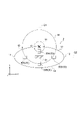
- the at least pair of magnetic field sensors 30 is identical to a pair of first sensors arranged on a first axis passing through the location of the downconductor 24 in a longitudinally intersecting cross section.
- the cross section includes a pair of second sensors arranged on a second axis that passes through the installation position of the down conductor 24 and is orthogonal to the first axis.
- they are arranged on an X-axis (first axis; shown by straight line Q2) passing through the installation position of the down conductor 24 in a cross section intersecting in the longitudinal direction.
- the magnetic field sensors 30C and 30D In the same cross section as the pair of first sensors, the magnetic field sensors 30C and 30D, the Y-axis (second axis; straight line Q1) that passes through the installation position of the down conductor 24 and is orthogonal to the X-axis (first axis). Includes a pair of second sensors, magnetic field sensors 30A, 30B, which are arranged above).
- a pair of first sensors on the above-mentioned X-axis (first axis) (for example, X-axis) in a cross section intersecting the longitudinal direction of the wind turbine blade 2.
- a pair of second sensors are arranged on the second axis (for example, Y axis) orthogonal to the first axis (X axis), so that the lightning current C is generated in the windmill blade 2.
- the flowed part can be specified in more detail. Therefore, the position of the lightning strike on the wind turbine blade 2 can be specified in more detail.
- the at least pair of magnetic field sensors 30 pass through the installation position of the downconductor 24 in the cross section described above, in addition to the pair of first sensor and pair of second sensors described above, and the first axis and Includes a pair of third sensors located on a third axis that intersects the second axis.
- a third axis (indicated by a straight line Q3) that intersects the X-axis (first axis) and the Y-axis (second axis) in a cross section that intersects in the longitudinal direction.
- a pair of magnetic field sensors 30E and 30F (third sensor) arranged above, and arranged on the third axis (indicated by the straight line Q4) intersecting the X-axis (first axis) and the Y-axis (second axis).
- a pair of magnetic field sensors 30G and 30H (third sensor) are included.
- the third axis intersecting the first axis and the second axis. Since the pair of third sensors (magnetometers 30D to 30H) are arranged on the shaft, the portion where the lightning current C flows in the wind turbine blade 2 can be specified in more detail. Therefore, the position of the lightning strike on the wind turbine blade 2 can be specified in more detail.
- the distance L1 between the magnetic field sensor 30 and the down conductor 24 in a cross section orthogonal to the longitudinal direction and the distance L2 between the magnetic field sensor 30 and the surface of the blade body 10 in the same cross section are 0. Satisfy 75 ⁇ L1 / L2 ⁇ 1.25.
- the above-mentioned distances L1 and L2 for the magnetic field sensor 30A are shown by L1A and L2A.
- the above-mentioned distances L1 and L2 for the magnetic field sensors 30B to 30D are L1B to L1D and L2B to L2D , respectively.
- the ratio of the distance L1 between the magnetic field sensor 30 and the down conductor 24 and the distance L2 between the magnetic field sensor 30 and the surface of the blade body 10 is close to 1, that is, L1 and L2 are the same. Degree. Therefore, the strength of the magnetic field generated around the lightning current at the position of the magnetic field sensor 30 is about the same when a lightning current of the same magnitude flows through the down conductor 24 and when it flows on the surface of the blade body 10. Become. Therefore, regardless of whether the lightning current C flows through the down conductor 24 or the blade body 10, the magnetic field M at the position of the magnetic field sensor 30 can be appropriately detected.
- At least a pair of magnetic field sensors 30 are provided in the longitudinal direction on the wing root 15 side of the center position of the wing tip 16 and the wing root 15 of the blade body 10.
- the wing root side sensor 32 is included.
- the length of the wing body 10 in the longitudinal direction is S, and the position of half the length (S / 2) from the wing root 15 or the wing tip 16 is the above-mentioned central position.
- the blade root side sensor 32 (magnetic field sensor 30) is provided in the region of the wind turbine blade 2 on the blade root 15 side through which the lightning current flowing toward the ground passes through the down conductor 24 or the blade body 10. Since it is provided, the magnetic field M generated around the lightning current C can be appropriately detected.
- At least a pair of magnetic field sensors 30 includes a plurality of pairs of magnetic field sensors 30 each provided at a plurality of positions in the longitudinal direction.
- the range of lightning strike positions in the longitudinal direction can be specified. Further, based on the determination result of the portion where the lightning current flows based on the detection result of the magnetic field sensor 30 at each position in the longitudinal direction, for example, the lightning current flowing through the blade body 10 is in the middle of the longitudinal direction in the wind turbine blade 2. It is possible to detect that the current has flowed into the down conductor 24.
- At least a pair of magnetic field sensors 30 are provided in the longitudinal direction on the wing root 15 side of the center position of the wing tip 16 and the wing root 15 of the blade body 10. It includes at least a pair of wing root side sensors 32 and a plurality of pairs of wing tip side sensors 34 provided on the wing tip 16 side from the above-mentioned center position.
- the number of blade tip side sensors 34 is larger than the number of blade root side sensors 32.
- the portion on the wing tip 16 side tends to be more easily struck by lightning than the portion on the wing root 15 side.
- blade tip side sensors 34 magnetic field sensors 30
- the blade tip 16 of the wind turbine blade 2 is relatively prone to lightning strikes.
- the part where the lightning current flows and the position of the lightning strike can be specified in more detail. Therefore, the position of the lightning strike can be efficiently specified while suppressing the number of magnetic field sensors 30 installed in the wind turbine blade 2 as a whole.
- the number of blade tip side sensors 34 in the first cross section orthogonal to the longitudinal direction is the second cross section orthogonal to the longitudinal direction. It is larger than the number of wing root side sensors 32 in (for example, the cross section at the position BB in FIG. 2).
- a pair of blade root side sensors 32 are arranged on both sides of the down conductor 24 in the X-axis direction, and the first blade tip 16 side is arranged.
- a pair of wing root side sensors 32 are arranged on both sides of the down conductor 24 in each of the X-axis direction and the Y-axis direction. May be good.
- the number of magnetic field sensors 30 in the cross section orthogonal to the longitudinal direction is increased on the blade tip 16 side as compared with the blade root 15 side, so that lightning strikes relatively among the wind turbine blades 2.
- the portion where the lightning current flows and the position of the lightning strike can be specified in more detail. Therefore, the position of the lightning strike can be efficiently specified while suppressing the number of magnetic field sensors 30 installed in the wind turbine blade 2 as a whole.
- the wind turbine blade (2) is Wing body (10) and A down conductor (24) extending along the longitudinal direction of the wing body, and A pair of magnetic field sensors (30) arranged at positions sandwiching the down conductor inside the wing body and for detecting a local magnetic field at each of the positions. To prepare for.
- the direction of the above-mentioned magnetic field at the position of the magnetic field sensor differs depending on the positional relationship between the portion where the lightning current flows in the wind turbine blade (down conductor or the blade body (shell, etc.), etc.) and the magnetic field sensor.
- the magnetic field detected by the magnetic field sensor when a lightning current flows through the wind turbine blade Based on the direction, it can be determined whether or not the lightning current has flowed through the down conductor.
- the lightning current has flowed through a part other than the down conductor (blade body, etc.), and the part where the receptacle is installed in the wind turbine blade. It can be identified that a lightning strike has occurred at a location other than the wing body (wing body, etc.). Therefore, the position of the lightning strike on the wind turbine blade can be appropriately specified.
- the lightning current may have a positive electrode property or a negative electrode property, and the direction of the magnetic field generated around the lightning current differs depending on the polarity of the lightning current.
- the polarity of the lightning current can be detected by the lightning current sensor provided on the path of the lightning current from the down conductor to the ground. Therefore, based on the direction of the magnetic field detected by the above-mentioned magnetic field sensor and the polarity of the lightning current detected by the lightning current sensor, the portion where the lightning current flows in the wind turbine blade can be specified in more detail. Therefore, the position of the lightning strike on the wind turbine blade can be specified in more detail.
- the lightning current flowing through the wing body toward the ground usually flows into the down conductor before reaching the ground. Therefore, even when a lightning strikes the wing body and a lightning current flows through the wing body, the polarity of the lightning current can be detected by the above-mentioned lightning current sensor. Further, if the magnitude of the lightning current is detected by the lightning current sensor, the degree of damage to the wind turbine blade due to the lightning strike can be estimated based on the magnitude of the detected lightning current. Therefore, the maintenance of the wind turbine blade can be effectively performed by utilizing the information related to the degree of damage of the wind turbine blade obtained in this way.
- the at least pair of magnetic field sensors With the first sensor arranged on the first axis (for example, the axis in the straight line Q2 direction described above) passing through the installation position of the down conductor in the cross section intersecting the longitudinal direction.
- the second sensor is arranged on a second axis (for example, the axis in the straight line Q1 direction described above) that passes through the installation position and is orthogonal to the first axis.
- the first sensor (magnetic field sensor) is arranged on the above-mentioned first axis in the cross section intersecting the longitudinal direction of the wind turbine blade, and the second sensor orthogonal to the first axis is arranged. Since the second sensor (magnetic field sensor) is arranged on the shaft, the portion where the lightning current flows in the wind turbine blade can be specified in more detail. Therefore, the position of the lightning strike on the wind turbine blade can be specified in more detail.
- the at least pair of magnetic field sensors pass through the installation position of the down conductor and cross the first axis and the second axis in the cross section (for example, in the straight line Q3 direction or the straight line Q4 direction described above). Includes a third sensor located on the axis).
- the ratio of the distance L1 between the magnetic field sensor and the down conductor and the distance L2 between the magnetic field sensor and the surface of the blade body is close to 1, that is, L1 and L2 are about the same. be. Therefore, the strength of the magnetic field generated around the lightning current at the position of the magnetic field sensor is about the same when a lightning current of the same magnitude flows through the down conductor and when it flows on the surface of the blade body. Therefore, regardless of whether the lightning current flows through the down conductor or the blade body, the magnetic field at the position of the magnetic field sensor can be appropriately detected.
- the down conductor is provided inside the blade body.
- the at least pair of magnetic field sensors includes a wing root side sensor (32) provided on the wing root side of the center position of the wing tip (16) and the wing root (15) of the wing body in the longitudinal direction. ..
- the blade root side sensor (magnetic field sensor) is provided in the region of the wind turbine blade on the blade root side through which the lightning current flowing toward the ground passes through the down conductor or the blade body. The magnetic field generated around the lightning current can be detected appropriately.
- the at least pair of magnetic field sensors includes a plurality of pairs of magnetic field sensors each provided at a plurality of positions in the longitudinal direction.
- the detection results of each of the pair of magnetic field sensors at each position in the longitudinal direction are obtained.
- the range of the lightning strike position in the longitudinal direction can be specified based on. Further, based on the determination result of the portion where the lightning current flows based on the detection result of at least a pair of magnetic field sensors at each position in the longitudinal direction, for example, the lightning current flowing through the blade body is in the middle of the longitudinal direction in the wind turbine blade. It is possible to detect that the current has flowed into the down conductor.
- the plurality of pairs of magnetic field sensors include at least a pair of wing root side sensors (32) provided on the wing root side of the center position of the wing tip and the wing root of the wing body in the longitudinal direction, and the center position. Includes a plurality of pairs of wing tip side sensors (34) provided on the wing tip side. The number of the plurality of pairs of wing tip side sensors is larger than the number of the at least pair of wing root side sensors.
- the lightning strike tends to occur more easily on the tip side of the wing than on the root side.
- the configuration of (9) above since a relatively large number of blade tip side sensors (magnetic field sensors) are provided in the blade tip side region, in the blade tip side region of the wind turbine blade where lightning strikes are relatively easy to occur. , The part where the lightning current flows and the position of the lightning strike can be specified in more detail. Therefore, the position of the lightning strike can be efficiently specified while suppressing the number of magnetic field sensors installed in the entire wind turbine blade.
- the number of the plurality of pairs of wing tip side sensors in the first cross section orthogonal to the longitudinal direction is larger than the number of the at least pair of wing root side sensors in the second cross section orthogonal to the longitudinal direction.
- the number of magnetic field sensors in the cross section orthogonal to the longitudinal direction is increased on the blade tip side as compared with the blade root side, so that lightning strikes are relatively easy among the wind turbine blades.
- the part where the lightning current flows and the position of the lightning strike can be specified in more detail. Therefore, the position of the lightning strike can be efficiently specified while suppressing the number of magnetic field sensors installed in the entire wind turbine blade.
- the monitoring device (50) is A wind turbine wing monitoring device comprising a wing body and a down conductor extending along the longitudinal direction of the wing body. At least a pair of magnetic field sensors provided in the wind turbine blade at a position sandwiching the down conductor inside the blade body and for detecting a local magnetic field at each of the positions.
- a lightning position information acquisition unit (42) for obtaining information on a lightning position of the wind turbine blade based on the detection signals of each of the at least a pair of magnetic field sensors, and a lightning position information acquisition unit (42). To prepare for.
- the wind power generation device (1) is The wind turbine rotor (5) including the wind turbine blade according to any one of (1) to (10) above, and A generator configured to be driven by the rotation of the wind turbine rotor, A monitoring device (50) including a lightning position information acquisition unit (42) for obtaining information on the lightning position of the wind turbine blade based on each detection signal of the at least pair of magnetic field sensors. To prepare for.
- the method for monitoring a wind turbine blade is as follows.
- a method for monitoring a wind turbine blade including a blade body (10) and a down conductor (24) extending along the longitudinal direction of the blade body.
- the present invention is not limited to the above-described embodiments, and includes a modified form of the above-described embodiments and a combination of these embodiments as appropriate.
- an expression representing a relative or absolute arrangement such as “in a certain direction”, “along a certain direction”, “parallel”, “orthogonal”, “center”, “concentric” or “coaxial”. Strictly represents not only such an arrangement, but also a tolerance or a state of relative displacement at an angle or distance to the extent that the same function can be obtained.
- expressions such as “same”, “equal”, and “homogeneous” that indicate that things are in the same state not only represent exactly the same state, but also have tolerances or differences to the extent that the same function can be obtained. It shall also represent the existing state.
- the expression representing a shape such as a quadrangular shape or a cylindrical shape not only represents a shape such as a quadrangular shape or a cylindrical shape in a geometrically strict sense, but also within a range in which the same effect can be obtained.
- the shape including the uneven portion, the chamfered portion, etc. shall also be represented.
- the expression “comprising”, “including”, or “having” one component is not an exclusive expression excluding the existence of another component.
Landscapes
- Engineering & Computer Science (AREA)
- Life Sciences & Earth Sciences (AREA)
- Sustainable Development (AREA)
- Sustainable Energy (AREA)
- Chemical & Material Sciences (AREA)
- Combustion & Propulsion (AREA)
- Mechanical Engineering (AREA)
- General Engineering & Computer Science (AREA)
- Wind Motors (AREA)
Abstract
Cette éolienne comprend : un corps de pale ; un conducteur descendant qui s'étend le long de la direction longitudinale du corps de pale ; et au moins une paire de capteurs de champ magnétique qui sont disposés à des positions à l'intérieur du corps de pale de façon à prendre en sandwich le conducteur descendant, et qui sont destinés à détecter un champ magnétique local au niveau de chacune desdites positions.
Priority Applications (2)
| Application Number | Priority Date | Filing Date | Title |
|---|---|---|---|
| EP21882796.2A EP4151855B1 (fr) | 2020-10-20 | 2021-10-19 | Pale d'éolienne, dispositif de surveillance de pale d'éolienne et procédé de surveillance de pale d'éolienne |
| US18/010,116 US11891978B2 (en) | 2020-10-20 | 2021-10-19 | Wind turbine blade, monitoring apparatus for wind turbine blade and wind power generating apparatus, and monitoring method for wind turbine blade |
Applications Claiming Priority (2)
| Application Number | Priority Date | Filing Date | Title |
|---|---|---|---|
| JP2020-176259 | 2020-10-20 | ||
| JP2020176259A JP7554091B2 (ja) | 2020-10-20 | 2020-10-20 | 風車翼、風車翼のモニタリング装置及び風力発電装置並びに風車翼のモニタリング方法 |
Publications (1)
| Publication Number | Publication Date |
|---|---|
| WO2022085655A1 true WO2022085655A1 (fr) | 2022-04-28 |
Family
ID=81289888
Family Applications (1)
| Application Number | Title | Priority Date | Filing Date |
|---|---|---|---|
| PCT/JP2021/038514 Ceased WO2022085655A1 (fr) | 2020-10-20 | 2021-10-19 | Pale d'éolienne, dispositif de surveillance de pale d'éolienne, dispositif de production d'énergie éolienne et procédé de surveillance de pale d'éolienne |
Country Status (4)
| Country | Link |
|---|---|
| US (1) | US11891978B2 (fr) |
| EP (1) | EP4151855B1 (fr) |
| JP (1) | JP7554091B2 (fr) |
| WO (1) | WO2022085655A1 (fr) |
Citations (6)
| Publication number | Priority date | Publication date | Assignee | Title |
|---|---|---|---|---|
| US20070041834A1 (en) * | 2005-08-17 | 2007-02-22 | Christian Schram | Device For Detecting Damage Of A Wind Energy Turbine Rotor Blade Due To A Lightning Strike |
| JP2012117446A (ja) * | 2010-11-30 | 2012-06-21 | Mitsubishi Heavy Ind Ltd | 落雷検出装置、これを備えた風車回転翼および風力発電装置 |
| US8258773B2 (en) | 2011-06-09 | 2012-09-04 | General Electric Company | System for detecting lightning strikes on wind turbine rotor blades |
| JP2017150827A (ja) * | 2016-02-22 | 2017-08-31 | 中部電力株式会社 | 雷撃検知装置及び雷撃検知方法 |
| JP2019120219A (ja) * | 2018-01-10 | 2019-07-22 | 株式会社日立製作所 | 風車ブレードの落雷判定システム及び方法 |
| JP2020176259A (ja) | 2019-04-15 | 2020-10-29 | 旭化成株式会社 | ポリアミド組成物及び成形品 |
Family Cites Families (5)
| Publication number | Priority date | Publication date | Assignee | Title |
|---|---|---|---|---|
| EP2385246A1 (fr) * | 2010-05-05 | 2011-11-09 | Siemens Aktiengesellschaft | Agencement pour la détection de foudre |
| US9835141B2 (en) * | 2011-07-28 | 2017-12-05 | Vestas Wind Systems A/S | Wind turbine blade and a lightning measurement system therein |
| JP2013148021A (ja) * | 2012-01-19 | 2013-08-01 | Mitsubishi Heavy Ind Ltd | 風車翼の損傷検出方法および損傷検出システム |
| JP6628395B2 (ja) | 2015-07-10 | 2020-01-08 | 国立研究開発法人 海上・港湾・航空技術研究所 | 外部雷保護システム、風車ブレード、及び風力発電装置 |
| EP3652434A1 (fr) * | 2017-07-11 | 2020-05-20 | Polytech A/S | Système de détection et d'évaluation de foudre et procédé de détection d'emplacement de foudroiements sur une pale d'éolienne |
-
2020
- 2020-10-20 JP JP2020176259A patent/JP7554091B2/ja active Active
-
2021
- 2021-10-19 US US18/010,116 patent/US11891978B2/en active Active
- 2021-10-19 EP EP21882796.2A patent/EP4151855B1/fr active Active
- 2021-10-19 WO PCT/JP2021/038514 patent/WO2022085655A1/fr not_active Ceased
Patent Citations (6)
| Publication number | Priority date | Publication date | Assignee | Title |
|---|---|---|---|---|
| US20070041834A1 (en) * | 2005-08-17 | 2007-02-22 | Christian Schram | Device For Detecting Damage Of A Wind Energy Turbine Rotor Blade Due To A Lightning Strike |
| JP2012117446A (ja) * | 2010-11-30 | 2012-06-21 | Mitsubishi Heavy Ind Ltd | 落雷検出装置、これを備えた風車回転翼および風力発電装置 |
| US8258773B2 (en) | 2011-06-09 | 2012-09-04 | General Electric Company | System for detecting lightning strikes on wind turbine rotor blades |
| JP2017150827A (ja) * | 2016-02-22 | 2017-08-31 | 中部電力株式会社 | 雷撃検知装置及び雷撃検知方法 |
| JP2019120219A (ja) * | 2018-01-10 | 2019-07-22 | 株式会社日立製作所 | 風車ブレードの落雷判定システム及び方法 |
| JP2020176259A (ja) | 2019-04-15 | 2020-10-29 | 旭化成株式会社 | ポリアミド組成物及び成形品 |
Non-Patent Citations (1)
| Title |
|---|
| See also references of EP4151855A4 |
Also Published As
| Publication number | Publication date |
|---|---|
| EP4151855A4 (fr) | 2024-05-29 |
| US20230265835A1 (en) | 2023-08-24 |
| US11891978B2 (en) | 2024-02-06 |
| EP4151855B1 (fr) | 2025-04-02 |
| EP4151855A1 (fr) | 2023-03-22 |
| JP2022067517A (ja) | 2022-05-06 |
| JP7554091B2 (ja) | 2024-09-19 |
Similar Documents
| Publication | Publication Date | Title |
|---|---|---|
| CN1916584B (zh) | 用于检测由于雷击造成风能涡轮机转子叶片损坏的装置 | |
| US9835141B2 (en) | Wind turbine blade and a lightning measurement system therein | |
| EP2533056B1 (fr) | Système de détection de foudres sur des pales de turbine éolienne | |
| CN102345567A (zh) | 用于雷电保护的装置 | |
| US8733164B2 (en) | Wind turbine optical wind sensor | |
| TWI662187B (zh) | 風力發電用葉片或風力發電裝置 | |
| BR102015028849B1 (pt) | Pá de rotor, turbina eólica e método para fabricar uma cobertura de longarina | |
| BRPI1107022A2 (pt) | Sistema pára-raios para pá de aerogerador com laminados de fibra de carbono | |
| PT1432911E (pt) | Sistema de alerta rápido para turbinas eólicas com sodar | |
| JP6628395B2 (ja) | 外部雷保護システム、風車ブレード、及び風力発電装置 | |
| JP2008115783A (ja) | 風車用ブレード | |
| EP2889476A1 (fr) | Rotor de turbine éolienne et turbine éolienne | |
| JP2015132245A (ja) | 風力発電装置 | |
| CN107288829A (zh) | 一种风力机叶片雷电接闪器设计方法 | |
| JP2023542378A (ja) | 風力タービン監視装置、風力タービンシステム、及び風力タービン監視方法 | |
| JP2019183806A (ja) | 風車ブレード及び風力発電システム | |
| WO2022085655A1 (fr) | Pale d'éolienne, dispositif de surveillance de pale d'éolienne, dispositif de production d'énergie éolienne et procédé de surveillance de pale d'éolienne | |
| JP2019120219A (ja) | 風車ブレードの落雷判定システム及び方法 | |
| US10487800B2 (en) | Wind turbines | |
| JP2010059813A (ja) | 被落雷物 | |
| CN114413876A (zh) | 一种风机机舱物理位置测量方法及装置 | |
| WO2022107786A1 (fr) | Système anti-foudre pour pale de turbine éolienne, installation de production d'énergie éolienne et procédé de surveillance de pale de turbine éolienne | |
| JP2020106032A (ja) | ダブルダウンコンダクタシステム、ダブルダウンコンダクタシステム用の健全性評価システム、及び風力発電装置 | |
| CN120187951A (zh) | 风力涡轮机叶片 | |
| TH2201006656A (th) | ระบบเฝ้าสังเกตระยะห่างของชุดกังหันลม, และวิธีการและอุปกรณ์เฝ้าสังเกต |
Legal Events
| Date | Code | Title | Description |
|---|---|---|---|
| 121 | Ep: the epo has been informed by wipo that ep was designated in this application |
Ref document number: 21882796 Country of ref document: EP Kind code of ref document: A1 |
|
| ENP | Entry into the national phase |
Ref document number: 2021882796 Country of ref document: EP Effective date: 20221213 |
|
| NENP | Non-entry into the national phase |
Ref country code: DE |
|
| WWG | Wipo information: grant in national office |
Ref document number: 2021882796 Country of ref document: EP |