WO2022092251A1 - 光ファイバケーブルおよび光ファイバユニット - Google Patents
光ファイバケーブルおよび光ファイバユニット Download PDFInfo
- Publication number
- WO2022092251A1 WO2022092251A1 PCT/JP2021/039970 JP2021039970W WO2022092251A1 WO 2022092251 A1 WO2022092251 A1 WO 2022092251A1 JP 2021039970 W JP2021039970 W JP 2021039970W WO 2022092251 A1 WO2022092251 A1 WO 2022092251A1
- Authority
- WO
- WIPO (PCT)
- Prior art keywords
- optical fiber
- water
- fiber core
- cross
- area
- Prior art date
- Legal status (The legal status is an assumption and is not a legal conclusion. Google has not performed a legal analysis and makes no representation as to the accuracy of the status listed.)
- Ceased
Links
Images


Classifications
-
- G—PHYSICS
- G02—OPTICS
- G02B—OPTICAL ELEMENTS, SYSTEMS OR APPARATUS
- G02B6/00—Light guides; Structural details of arrangements comprising light guides and other optical elements, e.g. couplings
- G02B6/44—Mechanical structures for providing tensile strength and external protection for fibres, e.g. optical transmission cables
- G02B6/4401—Optical cables
- G02B6/4403—Optical cables with ribbon structure
-
- G—PHYSICS
- G02—OPTICS
- G02B—OPTICAL ELEMENTS, SYSTEMS OR APPARATUS
- G02B6/00—Light guides; Structural details of arrangements comprising light guides and other optical elements, e.g. couplings
- G02B6/44—Mechanical structures for providing tensile strength and external protection for fibres, e.g. optical transmission cables
- G02B6/4401—Optical cables
- G02B6/441—Optical cables built up from sub-bundles
-
- G—PHYSICS
- G02—OPTICS
- G02B—OPTICAL ELEMENTS, SYSTEMS OR APPARATUS
- G02B6/00—Light guides; Structural details of arrangements comprising light guides and other optical elements, e.g. couplings
- G02B6/44—Mechanical structures for providing tensile strength and external protection for fibres, e.g. optical transmission cables
- G02B6/4401—Optical cables
- G02B6/4429—Means specially adapted for strengthening or protecting the cables
- G02B6/44384—Means specially adapted for strengthening or protecting the cables the means comprising water blocking or hydrophobic materials
Definitions
- This disclosure relates to an optical fiber cable and an optical fiber unit.
- Patent Document 1 discloses an optical fiber cable including an optical fiber unit aggregate in which a plurality of optical fiber units bundled with a plurality of fiber core wires are assembled.
- the optical fiber cable includes an external water blocking material provided on the outer periphery of the optical fiber unit assembly and an internal water blocking material provided inside the optical fiber unit assembly.
- the internal waterproof material is a water-expandable fiber or string-like member.
- Patent Document 2 discloses an optical fiber cable including a cable core composed of a plurality of optical fiber core wires. The portion of the optical fiber core wire located on the outer peripheral side of the cable core is wrapped with the first water absorbing tape. The centrally located portion of the optical fiber core of the cable core is wrapped with a first water-absorbing tape or a second water-absorbing tape, at least partially in the circumferential direction.
- Patent Document 3 discloses an optical fiber cable including an optical fiber unit composed of an optical fiber core wire or an optical fiber tape core wire, and a holding member wound around the outer periphery of the plurality of optical fiber units.
- the holding member has a water-absorbent material inside.
- the optical fiber cable of the present disclosure is with multiple optical fiber core wires, With multiple water-absorbent fibers,
- the ratio of the area of the water-absorbent fiber in the cross section to the area of the accommodating portion inside the jacket in the cross section orthogonal to the longitudinal direction of the optical fiber cable is 1% or more and 5% or less.
- the maximum value of the area of the gap portion surrounded by the optical fiber core wire in the cross section is 1.0 mm 2 or less.
- the optical fiber unit of the present disclosure is With multiple optical fiber core wires, With multiple water-absorbent fibers, A covering portion that covers the periphery of the plurality of optical fiber core wires and the plurality of water-absorbent fibers, and Equipped with The ratio of the area of the water-absorbent fiber in the cross section to the area of the accommodating portion inside the covering portion in the cross section orthogonal to the longitudinal direction of the optical fiber unit is 1% or more and 5% or less. The maximum value of the area of the gap portion surrounded by the optical fiber core wire in the cross section is 1.0 mm 2 or less.
- FIG. 1 is a cross-sectional view orthogonal to the longitudinal direction of the optical fiber cable according to the embodiment.
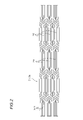
- FIG. 2 is a partially developed view showing an optical fiber ribbon used in an optical fiber cable in the longitudinal direction.
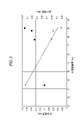
- FIG. 3 is a diagram showing the relationship between the waterproof characteristics and the bending characteristics of a cable on which an optical fiber core wire is mounted at high density.
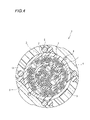
- FIG. 4 is a cross-sectional view showing a modified example of the optical fiber cable shown in FIG.
- FIG. 5 is a cross-sectional view orthogonal to the longitudinal direction of the optical fiber unit according to the embodiment.
- the present disclosure provides an optical fiber cable and an optical fiber unit capable of mounting an optical fiber core wire at a high density and having waterproofness. [Effect of this disclosure] According to the present disclosure, it is possible to provide an optical fiber cable and an optical fiber unit capable of mounting an optical fiber core wire at a high density and having waterproofness. [Explanation of Embodiments of the present disclosure] First, embodiments of the present disclosure will be listed and described.
- the optical fiber cable of the present disclosure is with multiple optical fiber core wires, With multiple water-absorbent fibers,
- the ratio of the area of the water-absorbent fiber in the cross section to the area of the accommodating portion inside the jacket in the cross section orthogonal to the longitudinal direction of the optical fiber cable is 1% or more and 5% or less.
- the maximum value of the area of the gap portion surrounded by the optical fiber core wire in the cross section is 1.0 mm 2 or less.
- an optical fiber cable capable of mounting an optical fiber core wire at a high density and having waterproofness.
- the internal porosity determined by the above may be 30% or more and 50% or less.
- the internal porosity is lower than 30%, the optical fiber core wire in the optical fiber cable becomes too dense and the bending characteristics deteriorate.
- the internal porosity is higher than 50%, the waterproof property is deteriorated.
- the internal porosity is 30% or more and 50% or less, good bending characteristics can be obtained while the optical fiber core wire is mounted at a high density to improve the waterproof property.
- the optical fiber core wire may have an outer diameter of 220 ⁇ m or less.
- the area of the void portion surrounded by the optical fiber core wire can be reduced by using the optical fiber core wire having a small diameter.
- the fineness of the water-absorbent fiber may be 5000 d (denier) or less.
- the water-absorbent fibers having a small diameter can be arranged even in a small void, so that the water-absorbent fibers can be arranged over a wide range of the accommodating portion inside the outer cover.
- a holding member that covers the periphery of the plurality of optical fiber core wires and the plurality of water-absorbent fibers.
- the holding member is arranged between the jacket and the plurality of optical fiber core wires and the plurality of water-absorbent fibers.
- the holding member may have water absorption.
- the holding member can prevent water from entering the accommodating portion inside the outer cover.
- a first holding member that covers a part of the plurality of optical fiber core wires, and It is provided with a second holding member that covers the periphery of another part of the plurality of optical fiber core wires arranged outside the first holding member.
- the first pressing member and the second pressing member may have water absorption.
- the first pressing member can prevent water from entering the inside of the first pressing member.
- the first pressing member can prevent water from entering the inside of the first pressing member.
- the distance between the optical fiber core wire and the first pressing member and the second pressing member is short, for example, the water-absorbing powder of the pressing member and the pressing member can be spread around the optical fiber core wire. Further, it is possible to distinguish between the optical fiber core wire arranged inside the first pressing member and the optical fiber core wire arranged outside the first pressing member.
- the optical fiber unit of the present disclosure is With multiple optical fiber core wires, With multiple water-absorbent fibers, A covering portion that covers the periphery of the plurality of optical fiber core wires and the plurality of water-absorbent fibers, and Equipped with The ratio of the area of the water-absorbent fiber in the cross section to the area of the accommodating portion inside the covering portion in the cross section orthogonal to the longitudinal direction of the optical fiber unit is 1% or more and 5% or less. The maximum value of the area of the gap portion surrounded by the optical fiber core wire in the cross section is 1.0 mm 2 or less.
- an optical fiber unit capable of mounting an optical fiber core wire at a high density and having waterproofness.
- the optical fiber cable 1 includes a plurality of optical fiber core wires 2, a plurality of water-absorbent fibers 3, and a jacket 4.
- a plurality of optical fiber core wires 2 and a plurality of water-absorbing fibers 3 are arranged in the accommodating portion S inside the outer cover 4.
- the optical fiber core wire 2 forms an optical fiber ribbon 21.
- 36 optical fiber ribbons 21 formed by 12 optical fiber core wires 2 are twisted together.
- a plurality of optical fiber ribbons 21 may be twisted together to form an aggregate, and the plurality of aggregates may be further twisted together.
- a bundle material may be wound around the aggregate of the optical fiber ribbon 21.
- the optical fiber ribbon 21 has a plurality of optical fiber core wires 2 arranged in parallel in a direction orthogonal to the longitudinal direction thereof, and some adjacent optical fiber core wires 2 are connected to each other. It has a configuration in which the connecting portion 211 is formed.
- the connecting portion 211 is intermittently formed along the optical fiber core wire 2, and the connecting portion 211 and the non-connecting portion 212 are alternately formed along the optical fiber core wire 2.
- the optical fiber core wire 2 is composed of, for example, a glass fiber composed of a core and a clad, and one layer or a plurality of covering layers surrounding the glass fiber.
- the optical fiber core wire 2 has, for example, an outer diameter of 220 ⁇ m or less.
- the water-absorbent fiber 3 contains, for example, a water-absorbent yarn made of polyester fiber or the like.
- a polyester fiber for example, a polyester fiber having a water absorption rate of 30 g / min or less in tap water is used.
- the outer cover 4 covers the periphery of the plurality of optical fiber core wires 2 and the plurality of water-absorbent fibers 3.
- the jacket 4 is formed of a hard resin having a relatively high Young's modulus, such as high-density polyethylene.
- a plurality of tension members 5 and a plurality of tear strings 6 may be embedded in the outer cover 4.
- the tension member 5 may be formed of, for example, a fiber reinforced plastic (FRP) such as aramid FRP, glass FRP, carbon FRP, or a metal wire.
- FRP fiber reinforced plastic
- the water-absorbent fiber 3 is provided so that the ratio of the cross-sectional area of the water-absorbent fiber 3 to the cross-sectional area of the accommodating portion S inside the outer cover 4 is 1% or more and 5% or less. Be placed. Further, in the optical fiber cable 1, the optical fiber ribbon 21 is arranged so that the maximum cross-sectional area of the gap S1 surrounded by the optical fiber ribbon 21 is 1.0 mm 2 or less.
- the cross-sectional area is an area in a cross section orthogonal to the longitudinal direction of the optical fiber cable 1.
- the transmission characteristics of the optical fiber core wire 2 deteriorate due to moisture. That is, when water intrudes into the accommodating portion S inside the outer cover 4 due to damage to the outer cover 4 or permeation of moisture in the optical fiber cable 1, the transmission characteristics of the optical fiber core wire 2 may deteriorate. Further, when water infiltrates into the gap of the optical fiber ribbon 21, the water may infiltrate over a wide range in the longitudinal direction of the cable due to the water being transmitted through the gap. The transmission of water in the accommodating portion S of the optical fiber cable 1 is called water running.
- the penetration depth of the liquid is proportional to the root (1/2 power) of the capillary radius. That is, the smaller the radius and the cross-sectional area of the gap S1, the smaller the penetration depth of the liquid and the better the waterproof property.
- the maximum value of the cross-sectional area of the gap portion S1 is 1.0 mm 2 or less.
- the waterproof property can be particularly improved. That is, it is possible to suppress the occurrence of water running in the gap portion S1.
- the ratio of the cross-sectional area of the water-absorbent fiber 3 to the cross-sectional area of the accommodating portion S is set to 1% or more and 5% or less. Therefore, the water-absorbent fiber 3 housed in the storage portion S inside the outer cover 4 can absorb the water that has invaded the inside of the outer cover 4. As a result, it is possible to improve the waterproof property while mounting the optical fiber core wire 2 at a high density.
- the gap S1 surrounded by the optical fiber ribbon 21 includes both the gap surrounded by the optical fiber ribbon 21 alone and the gap surrounded by the plurality of optical fiber ribbons 21, and is adjacent to each other.
- a space surrounded by a plurality of optical fiber core wires 2 in which the fiber core wires 2 are in contact with each other without a gap is shown.
- the optical fiber cable 1 is formed so that the maximum cross-sectional area of the gap portion is 1.0 mm 2 or less.
- the optical fiber core wire 2 has an outer diameter of 220 ⁇ m or less.
- the optical fiber core wire 2 having a small diameter if the internal porosity is 30% or more and 50% or less, the maximum value of the area of the void portion S1 surrounded by the optical fiber ribbon 21 can be reduced.
- the maximum value of the cross-sectional area of the void portion can be 1.0 mm 2 or less.
- the optical fiber cable 1 of the present embodiment may include a holding member 7 arranged between the outer cover 4, the plurality of optical fiber ribbons 21, and the plurality of water-absorbent fibers 3.
- the pressing member 7 covers the periphery of the plurality of optical fiber ribbons 21 and the plurality of water-absorbent fibers 3.
- the pressing member 7 is formed of, for example, a non-woven fabric made of polyester or the like. Further, the pressing member 7 may have water absorption. When the pressing member 7 has water absorption, the pressing member 7 is formed by adhering the water-absorbing powder to, for example, a base cloth made of polyester or the like.
- the pressing member 7 may be vertically attached or spirally wound around the plurality of optical fiber ribbons 21.
- the presser member 7 When the presser member 7 is wound vertically, the presser member 7 is wound so that the longitudinal direction of the presser member 7 is parallel to the longitudinal direction of the optical fiber cable 1 and the width direction of the presser member 7 is along the circumferential direction of the optical fiber cable 1. 7 means a state in which the fiber optic ribbon 21 is wound around the optical fiber ribbon 21.
- the optical fiber cable 1 of the present embodiment may be formed so that the internal porosity obtained by dividing the internal porosity area by the cross-sectional area of the accommodating portion S is 30% or more and 50% or less.
- the accommodating portion S is a space closed by the holding member 7, and the cross-sectional area of the accommodating portion S is calculated based on the inner diameter of the holding member 7.
- the accommodating portion S is a space closed by the outer cover 4, and the cross-sectional area of the accommodating portion S is calculated based on the inner diameter of the outer cover 4.
- the internal void area is obtained by subtracting the cross-sectional area of the plurality of optical fiber ribbons 21 from the cross-sectional area of the accommodating portion S.
- the waterproof property becomes better.
- the horizontal axis represents the internal porosity
- the vertical axis represents the running water speed or bending characteristics.
- the white triangles indicate the values of bending characteristics
- the black circles indicate the values of Hashirimizu speed.
- the optical fiber cable 1 of the present embodiment has an internal void ratio of 30% or more and 50% or less, it is possible to obtain good bending characteristics while improving waterproofness by mounting the optical fiber core wire 2 at a high density.
- the optical fiber cable 1 of the present embodiment may include the water-absorbent fiber 3 having a fineness of 5000 d or less as the water-absorbent fiber 3. Since the water-absorbent fiber 3 having a small diameter can be arranged even in a small void, the water-absorbent fiber 3 can be arranged over a wide range of the accommodating portion S inside the outer cover 4.
- the optical fiber cable 1 of the present embodiment may further include a pressing member 8 inside the pressing member 7 in addition to the pressing member 7.
- the pressing member 7 is an example of a second pressing member
- the pressing member 8 is an example of a first pressing member.
- the holding member 8 covers a part of the plurality of optical fiber ribbons 21.
- the pressing member 8 is formed of, for example, a non-woven fabric made of polyester or the like. Further, the pressing member 8 has water absorption, and may be formed by adhering the water absorption powder to a base cloth made of, for example, polyester or the like.
- the pressing member 8 is vertically attached or spirally wound around the plurality of optical fiber ribbons 21.
- the water-absorbent fiber 3 may be arranged only inside the pressing member 8 or may be arranged inside and outside the pressing member 8.
- FIG. 5 is a diagram showing an example of the optical fiber unit 11.
- the optical fiber unit 11 includes a plurality of optical fiber core wires 12, a plurality of water-absorbent fibers 13, and a covering portion 14.
- a plurality of optical fiber core wires 12 and a plurality of water-absorbing fibers 13 are arranged in the accommodating portion S10 inside the covering portion 14.
- the optical fiber core wire 12 forms an optical fiber ribbon 121.
- the plurality of optical fiber ribbons 121 are put together by being twisted together.
- three optical fiber ribbons 21 formed by twelve optical fiber core wires 2 are twisted together.
- the optical fiber ribbon 121 is configured in the same manner as the optical fiber ribbon 21 of FIG. That is, the optical fiber ribbon 121 has a configuration in which a plurality of optical fiber core wires 12 are arranged in parallel in a direction orthogonal to the longitudinal direction thereof, and some adjacent optical fiber core wires 12 are connected to form a connecting portion 211.
- the connecting portion 211 is intermittently formed along the optical fiber core wire 2, and the connecting portion 211 and the non-connecting portion 212 are alternately formed along the optical fiber core wire 12.
- the optical fiber core wire 12 is composed of, for example, a glass fiber composed of a core and a clad, and one layer or a plurality of covering layers surrounding the glass fiber.
- the optical fiber core wire 12 has, for example, an outer diameter of 220 ⁇ m or less.
- the water-absorbent fiber 13 contains, for example, a water-absorbent yarn made of polyester or the like.
- a polyester fiber for example, a polyester fiber having a water absorption rate of 30 g / min or less in tap water is used.
- the covering portion 14 covers the periphery of the plurality of optical fiber core wires 12 and the plurality of water-absorbing fibers 13.
- the covering portion 14 can be formed of a hard resin having a relatively high Young's modulus, for example, high-density polyethylene.
- the covering portion 14 may be composed of a member having low strength and a low elongation rate so that the covering portion 14 can be torn by the tear string.
- the water-absorbent fiber 13 is provided so that the ratio of the cross-sectional area of the water-absorbent fiber 13 to the cross-sectional area of the accommodating portion S10 inside the covering portion 14 is 1% or more and 5% or less. Be placed. Further, the optical fiber ribbon 121 is arranged so that the maximum cross-sectional area of the gap S11 surrounded by the optical fiber ribbon 121 is 1.0 mm 2 or less.
- the cross-sectional area is an area in a cross section orthogonal to the longitudinal direction of the optical fiber unit 11.
- the waterproof property can be particularly improved by setting the maximum value of the cross-sectional area of the gap portion S11 to 1.0 mm 2 or less. That is, it is possible to suppress the occurrence of water running in the gap portion S11. Further, the water-absorbent fiber 13 housed in the housing portion S10 inside the covering portion 14 can absorb the water that has invaded the inside of the covering portion 14. As a result, it is possible to improve the waterproof property while mounting the optical fiber core wire 2 at a high density.
- optical fiber unit 11 may be mounted in the optical fiber cable.
- the optical fiber ribbon 21 is formed of 12 optical fiber core wires 2. However, the number of optical fiber core wires 2 forming the optical fiber ribbon 21 can be appropriately changed. Similarly, the optical fiber ribbon 121 is formed by 12 optical fiber core wires 12. However, the number of optical fiber core wires 12 forming the optical fiber ribbon 121 can be appropriately changed.
- the optical fiber cable 1 and the optical fiber unit 11 have an optical fiber ribbon 21 and an optical fiber ribbon 121 in the form of the optical fiber core wire 2 and the optical fiber core wire 12.
- the optical fiber cable 1 may have the optical fiber core wire 2 as a single-core optical fiber core wire instead of the optical fiber ribbon.
- the optical fiber unit 11 may have the optical fiber core wire 12 as a single core optical fiber core wire instead of the optical fiber ribbon.
- a plurality of single-core optical fiber core wires may be twisted together to form an aggregate, or a bundle material may be wound around the aggregate.
- the optical fiber cable 1 is formed so that the maximum cross-sectional area of the gap portion surrounded by the plurality of optical fiber core wires 2 is 1.0 mm 2 or less.
- the optical fiber unit 11 is formed so that the maximum cross-sectional area of the gap portion surrounded by the plurality of optical fiber core wires 12 is 1.0 mm 2 or less.
- the non-woven fabric tape that does not absorb water was used for the presser winding member 7.
- the maximum area of the gap portion the area surrounded by the plurality of optical fiber ribbons 21 was calculated based on the cross-sectional photograph of the optical fiber cable 1.
- the running water speed (m / h) was evaluated by holding the sample in artificial seawater at room temperature for 240 hours and measuring the length of running water during that period.
- the evaluation of the running water speed for each sample was judged by whether or not the running water speed satisfied less than 0.12 m / h. If the running water speed is less than 0.12 m / h, it is judged that the waterproof property is good, and if the running water speed is 0.10 m / h or more and less than 0.12 m / h, it is evaluated B, and the running water speed is 0. A rating of less than .10 m / h was given as evaluation A. Further, if the running water speed was 0.12 m / h or more, it was judged that the waterproof property was inferior, and the evaluation was C. That is, the sample of evaluation A or evaluation B is an optical fiber cable having good waterproofness.
- the evaluation of the bending characteristics for each sample was judged by whether or not the bending characteristics satisfied less than 0.15 dB / c. If the bending characteristic is less than 0.15 dB / c, it is judged that the bending characteristic is good, and the one having the bending characteristic of 0.10 dB / c or more and less than 0.15 dB / c is evaluated B, and the bending characteristic is 0.10 dB /. Those less than c were evaluated as evaluation A. Further, if the bending characteristic is 0.15 dB / c or more, it is judged that the bending characteristic is inferior, and the evaluation is C. That is, the sample of evaluation A or evaluation B is an optical fiber cable having good bending characteristics.
- Optical fiber cable 2 Optical fiber core wire 3: Water-absorbent fiber 4: Cover 5: Tension member 6: Tear string 7, 8: Pressing member 11: Optical fiber unit 12: Optical fiber core wire 13: Water-absorbing Sex fiber 14: Covering part 21: Optical fiber ribbon 121: Optical fiber ribbon 211: Connecting part 212: Non-connecting part S, S10: Accommodating part S1, S11: Void part
Landscapes
- Physics & Mathematics (AREA)
- General Physics & Mathematics (AREA)
- Optics & Photonics (AREA)
- Insulated Conductors (AREA)
Abstract
Description
1<[d2-(d-2h)2]/(d2×S/100)<2
複数の光ファイバ心線と、
複数の吸水性繊維と、
前記複数の光ファイバ心線および前記複数の吸水性繊維の周囲を被覆する外被と、
を備えており、
光ファイバケーブルの長手方向に直交する断面における前記外被より内側の収容部の面積に対する前記吸水性繊維の前記断面における面積の割合は1%以上5%以下であり、
前記断面における前記光ファイバ心線に囲まれた空隙部の面積の最大値は1.0mm2以下である。
複数の光ファイバ心線と、
複数の吸水性繊維と、
前記複数の光ファイバ心線および前記複数の吸水性繊維の周囲を被覆する被覆部と、
を備えており、
光ファイバユニットの長手方向に直交する断面における前記被覆部より内側の収容部の面積に対する前記吸水性繊維の前記断面における面積の割合は1%以上5%以下であり、
前記断面における前記光ファイバ心線に囲まれた空隙部の面積の最大値は1.0mm2以下である。
本開示は、光ファイバ心線を高密度に実装可能であり、かつ、防水性を有する光ファイバケーブルおよび光ファイバユニットを提供する。
[本開示の効果]
本開示によれば、光ファイバ心線を高密度に実装可能であり、かつ、防水性を有する光ファイバケーブルおよび光ファイバユニットを提供することができる。
[本開示の実施の形態の説明]
まず本開示の実施態様を列記して説明する。
(1)本開示の光ファイバケーブルは、
複数の光ファイバ心線と、
複数の吸水性繊維と、
前記複数の光ファイバ心線および前記複数の吸水性繊維の周囲を被覆する外被と、
を備えており、
光ファイバケーブルの長手方向に直交する断面における前記外被より内側の収容部の面積に対する前記吸水性繊維の前記断面における面積の割合は1%以上5%以下であり、
前記断面における前記光ファイバ心線に囲まれた空隙部の面積の最大値は1.0mm2以下である。
前記押さえ部材は、前記外被と前記複数の光ファイバ心線および前記複数の吸水性繊維との間に配置されており、
前記押さえ部材は、吸水性を有してもよい。
前記第一押さえ部材の外側に配置された前記複数の光ファイバ心線の他の一部の周囲を覆う第二押さえ部材と、を備えており、
前記第一押さえ部材および前記第二押さえ部材は、吸水性を有してもよい。
複数の光ファイバ心線と、
複数の吸水性繊維と、
前記複数の光ファイバ心線および前記複数の吸水性繊維の周囲を被覆する被覆部と、
を備えており、
光ファイバユニットの長手方向に直交する断面における前記被覆部より内側の収容部の面積に対する前記吸水性繊維の前記断面における面積の割合は1%以上5%以下であり、
前記断面における前記光ファイバ心線に囲まれた空隙部の面積の最大値は1.0mm2以下である。
本開示の光ファイバケーブルおよび光ファイバユニットの具体例を、図面を参照しつつ説明する。なお、本開示はこれらの例示に限定されるものではなく、請求の範囲によって示され、請求の範囲と均等の意味及び範囲内でのすべての変更が含まれることが意図される。
図1を参照して、第一実施形態に係る光ファイバケーブル1の構成について説明する。
本実施形態に係る光ファイバケーブル1において、内部空隙率、空隙部の最大面積、内部空隙面積に対する吸水性繊維の面積(吸水性繊維占有率)の3つのパラメータを変化させたサンプルNo.1からNo.19を用意した。光ファイバケーブル1において押さえ巻き部材7は非吸水の不織布テープを使用した。空隙部の最大面積は、光ファイバケーブル1の断面写真に基づいて複数の光ファイバリボン21により囲まれる面積を算出した。各サンプルに対して、サンプルを人工海水の中に常温で240時間保持し、その間に水走りした長さを測定することにより走水速度(m/h)の評価を行った。また、各サンプルに対して、ケーブルの外径の10倍の曲げ半径において±180°の曲げ試験を10サイクル行うことにより、曲げ試験中での波長1.55μmのロス増の大きさ(曲げ特性(dB/c))の評価を行った。以下の表1に、サンプルNo.1から19に対する防水性および曲げ特性の評価結果を示す。

2:光ファイバ心線
3:吸水性繊維
4:外被
5:テンションメンバ
6:引き裂き紐
7、8:押さえ部材
11:光ファイバユニット
12:光ファイバ心線
13:吸水性繊維
14:被覆部
21:光ファイバリボン
121:光ファイバリボン
211:連結部
212:非連結部
S、S10:収容部
S1、S11:空隙部
Claims (7)
- 複数の光ファイバ心線と、
複数の吸水性繊維と、
前記複数の光ファイバ心線および前記複数の吸水性繊維の周囲を被覆する外被と、
を備えており、
光ファイバケーブルの長手方向に直交する断面における前記外被より内側の収容部の面積に対する前記吸水性繊維の前記断面における面積の割合は1%以上5%以下であり、
前記断面における前記光ファイバ心線に囲まれた空隙部の面積の最大値は1.0mm2以下である、光ファイバケーブル。 - 前記断面における前記外被より内側の収容部の面積から前記断面における前記複数の光ファイバ心線の面積を減ずることにより求められた内部空隙面積を、前記収容部の面積で除することにより求められる内部空隙率は、30%以上50%以下である、請求項1に記載の光ファイバケーブル。
- 前記光ファイバ心線は220μm以下の外径を有する、請求項1または請求項2に記載の光ファイバケーブル。
- 前記吸水性繊維の繊度は5000d以下である、請求項1から請求項3のいずれか一項に記載の光ファイバケーブル。
- 前記複数の光ファイバ心線および前記複数の吸水性繊維の周囲を覆う押さえ部材を備えており、
前記押さえ部材は、前記外被と前記複数の光ファイバ心線および前記複数の吸水性繊維との間に配置されており、
前記押さえ部材は、吸水性を有する、請求項1から請求項4のいずれか一項に記載の光ファイバケーブル。 - 前記複数の光ファイバ心線の一部の周囲を覆う第一押さえ部材と、
前記第一押さえ部材の外側に配置された前記複数の光ファイバ心線の他の一部の周囲を覆う第二押さえ部材と、を備えており、
前記第一押さえ部材および前記第二押さえ部材は、吸水性を有する、請求項1から請求項4のいずれか一項に記載の光ファイバケーブル。 - 複数の光ファイバ心線と、
複数の吸水性繊維と、
前記複数の光ファイバ心線および前記複数の吸水性繊維の周囲を被覆する被覆部と、
を備えており、
光ファイバユニットの長手方向に直交する断面における前記被覆部より内側の収容部の面積に対する前記吸水性繊維の前記断面における面積の割合は1%以上5%以下であり、
前記断面における前記光ファイバ心線に囲まれた空隙部の面積の最大値は1.0mm2以下である、光ファイバユニット。
Priority Applications (3)
| Application Number | Priority Date | Filing Date | Title |
|---|---|---|---|
| US18/003,400 US12313894B2 (en) | 2020-10-30 | 2021-10-29 | Optical fiber cable and optical fiber unit |
| JP2022559255A JPWO2022092251A1 (ja) | 2020-10-30 | 2021-10-29 | |
| EP21886368.6A EP4239384A4 (en) | 2020-10-30 | 2021-10-29 | Optical fiber cable and optical fiber unit |
Applications Claiming Priority (2)
| Application Number | Priority Date | Filing Date | Title |
|---|---|---|---|
| JP2020182420 | 2020-10-30 | ||
| JP2020-182420 | 2020-10-30 |
Publications (1)
| Publication Number | Publication Date |
|---|---|
| WO2022092251A1 true WO2022092251A1 (ja) | 2022-05-05 |
Family
ID=81383990
Family Applications (1)
| Application Number | Title | Priority Date | Filing Date |
|---|---|---|---|
| PCT/JP2021/039970 Ceased WO2022092251A1 (ja) | 2020-10-30 | 2021-10-29 | 光ファイバケーブルおよび光ファイバユニット |
Country Status (4)
| Country | Link |
|---|---|
| US (1) | US12313894B2 (ja) |
| EP (1) | EP4239384A4 (ja) |
| JP (1) | JPWO2022092251A1 (ja) |
| WO (1) | WO2022092251A1 (ja) |
Cited By (3)
| Publication number | Priority date | Publication date | Assignee | Title |
|---|---|---|---|---|
| WO2025134902A1 (ja) * | 2023-12-21 | 2025-06-26 | 株式会社フジクラ | 光ファイバケーブル |
| WO2025197080A1 (ja) * | 2024-03-22 | 2025-09-25 | Ntt株式会社 | 光ファイバケーブル |
| WO2025263539A1 (ja) * | 2024-06-21 | 2025-12-26 | 住友電気工業株式会社 | 光ファイバケーブル |
Families Citing this family (1)
| Publication number | Priority date | Publication date | Assignee | Title |
|---|---|---|---|---|
| US12504578B2 (en) * | 2023-02-20 | 2025-12-23 | Sterlite Technologies Limited | Multicore optical fiber and multicore optical fiber cable |
Citations (14)
| Publication number | Priority date | Publication date | Assignee | Title |
|---|---|---|---|---|
| JPH11183764A (ja) * | 1997-12-24 | 1999-07-09 | Sumitomo Electric Ind Ltd | 光ファイバケーブル |
| JP2001194567A (ja) * | 2000-01-11 | 2001-07-19 | Sumitomo Electric Ind Ltd | 光ファイバケーブル |
| JP2002236241A (ja) * | 2001-02-08 | 2002-08-23 | Fujikura Ltd | 光ケーブル |
| JP2006337581A (ja) * | 2005-05-31 | 2006-12-14 | Swcc Showa Cable Systems Co Ltd | 光ファイバケーブル |
| JP2012508395A (ja) * | 2008-11-07 | 2012-04-05 | ドラカ・コムテツク・ベー・ベー | 小径光ファイバ |
| JP2013088542A (ja) | 2011-10-17 | 2013-05-13 | Furukawa Electric Co Ltd:The | 光ファイバケーブル |
| JP2015102576A (ja) | 2013-11-21 | 2015-06-04 | 株式会社フジクラ | 光ファイバケーブル |
| US20150370026A1 (en) * | 2014-06-23 | 2015-12-24 | Corning Optical Communications LLC | Optical fiber cable |
| JP2017009922A (ja) * | 2015-06-25 | 2017-01-12 | 古河電気工業株式会社 | 光ファイバケーブル、光ファイバケーブルの製造方法 |
| JP2018136376A (ja) * | 2017-02-20 | 2018-08-30 | 株式会社フジクラ | 光ファイバケーブル |
| JP2018169431A (ja) | 2017-03-29 | 2018-11-01 | 古河電気工業株式会社 | 光ファイバケーブル |
| WO2018221142A1 (ja) * | 2017-06-02 | 2018-12-06 | 株式会社フジクラ | 光ファイバケーブル及び光ファイバケーブルの製造方法 |
| JP2020076915A (ja) * | 2018-11-09 | 2020-05-21 | 株式会社フジクラ | 光ファイバケーブル |
| JP2020182420A (ja) | 2019-05-08 | 2020-11-12 | 株式会社オーイズミ | 吸殻消火装置 |
Family Cites Families (6)
| Publication number | Priority date | Publication date | Assignee | Title |
|---|---|---|---|---|
| US6229944B1 (en) | 1997-02-04 | 2001-05-08 | Sumitomo Electric Industries, Ltd. | Optical fiber cable |
| US7936957B1 (en) * | 2007-03-09 | 2011-05-03 | Superior Essex Communications, Lp | High-density fiber optic ribbon cable with enhanced water blocking performance |
| JP2015215448A (ja) * | 2014-05-09 | 2015-12-03 | 株式会社フジクラ | 光ファイバケーブル |
| JP2016075815A (ja) * | 2014-10-07 | 2016-05-12 | 住友電気工業株式会社 | 光ファイバケーブル及び光ファイバケーブルの製造方法 |
| EP3605174B1 (en) * | 2017-03-21 | 2024-10-30 | Sumitomo Electric Industries, Ltd. | Optical fiber cable |
| AU2019338756B2 (en) | 2018-09-11 | 2022-01-13 | Fujikura Ltd. | Optical fiber cable |
-
2021
- 2021-10-29 JP JP2022559255A patent/JPWO2022092251A1/ja active Pending
- 2021-10-29 US US18/003,400 patent/US12313894B2/en active Active
- 2021-10-29 EP EP21886368.6A patent/EP4239384A4/en not_active Withdrawn
- 2021-10-29 WO PCT/JP2021/039970 patent/WO2022092251A1/ja not_active Ceased
Patent Citations (14)
| Publication number | Priority date | Publication date | Assignee | Title |
|---|---|---|---|---|
| JPH11183764A (ja) * | 1997-12-24 | 1999-07-09 | Sumitomo Electric Ind Ltd | 光ファイバケーブル |
| JP2001194567A (ja) * | 2000-01-11 | 2001-07-19 | Sumitomo Electric Ind Ltd | 光ファイバケーブル |
| JP2002236241A (ja) * | 2001-02-08 | 2002-08-23 | Fujikura Ltd | 光ケーブル |
| JP2006337581A (ja) * | 2005-05-31 | 2006-12-14 | Swcc Showa Cable Systems Co Ltd | 光ファイバケーブル |
| JP2012508395A (ja) * | 2008-11-07 | 2012-04-05 | ドラカ・コムテツク・ベー・ベー | 小径光ファイバ |
| JP2013088542A (ja) | 2011-10-17 | 2013-05-13 | Furukawa Electric Co Ltd:The | 光ファイバケーブル |
| JP2015102576A (ja) | 2013-11-21 | 2015-06-04 | 株式会社フジクラ | 光ファイバケーブル |
| US20150370026A1 (en) * | 2014-06-23 | 2015-12-24 | Corning Optical Communications LLC | Optical fiber cable |
| JP2017009922A (ja) * | 2015-06-25 | 2017-01-12 | 古河電気工業株式会社 | 光ファイバケーブル、光ファイバケーブルの製造方法 |
| JP2018136376A (ja) * | 2017-02-20 | 2018-08-30 | 株式会社フジクラ | 光ファイバケーブル |
| JP2018169431A (ja) | 2017-03-29 | 2018-11-01 | 古河電気工業株式会社 | 光ファイバケーブル |
| WO2018221142A1 (ja) * | 2017-06-02 | 2018-12-06 | 株式会社フジクラ | 光ファイバケーブル及び光ファイバケーブルの製造方法 |
| JP2020076915A (ja) * | 2018-11-09 | 2020-05-21 | 株式会社フジクラ | 光ファイバケーブル |
| JP2020182420A (ja) | 2019-05-08 | 2020-11-12 | 株式会社オーイズミ | 吸殻消火装置 |
Non-Patent Citations (1)
| Title |
|---|
| See also references of EP4239384A4 |
Cited By (3)
| Publication number | Priority date | Publication date | Assignee | Title |
|---|---|---|---|---|
| WO2025134902A1 (ja) * | 2023-12-21 | 2025-06-26 | 株式会社フジクラ | 光ファイバケーブル |
| WO2025197080A1 (ja) * | 2024-03-22 | 2025-09-25 | Ntt株式会社 | 光ファイバケーブル |
| WO2025263539A1 (ja) * | 2024-06-21 | 2025-12-26 | 住友電気工業株式会社 | 光ファイバケーブル |
Also Published As
| Publication number | Publication date |
|---|---|
| EP4239384A4 (en) | 2024-04-24 |
| EP4239384A1 (en) | 2023-09-06 |
| US12313894B2 (en) | 2025-05-27 |
| JPWO2022092251A1 (ja) | 2022-05-05 |
| US20230251445A1 (en) | 2023-08-10 |
Similar Documents
| Publication | Publication Date | Title |
|---|---|---|
| US12313894B2 (en) | Optical fiber cable and optical fiber unit | |
| KR100264018B1 (ko) | 방수 및 강도성질을 제공하는 코어 랩 바인더를 구비한 통신 케이블 | |
| CA2247677A1 (en) | Fiber optic cable with ripcord | |
| CN101765797A (zh) | 光纤电缆 | |
| JP6598813B2 (ja) | 光ファイバケーブル | |
| JP7800448B2 (ja) | 光ファイバケーブル及びコネクタ付きケーブル | |
| KR20190128729A (ko) | 광섬유 케이블 | |
| TW202227868A (zh) | 光纖電纜 | |
| JP2006514324A (ja) | 直線集合構造のルースチューブ型光ケーブル | |
| JP2010139631A (ja) | 光ファイバケーブル | |
| JP5947558B2 (ja) | 光ファイバケーブル | |
| JP6004627B2 (ja) | 光ファイバケーブル | |
| JP2019159078A (ja) | 光ファイバケーブル | |
| JP4652618B2 (ja) | 光ファイバケーブル | |
| JP2016075814A (ja) | 光ファイバケーブル | |
| JP2008191209A (ja) | ルース型光ファイバコード | |
| JP4460035B2 (ja) | 光ファイバケーブル | |
| JP2004287223A (ja) | 光ファイバケーブル | |
| JPS6173113A (ja) | 防水型光フアイバケ−ブル | |
| JP2024010847A (ja) | 光ファイバケーブル | |
| JP2006337581A (ja) | 光ファイバケーブル | |
| CN210323510U (zh) | 一种耐腐蚀的抗拉松套层绞式光缆 | |
| RU226378U1 (ru) | Оптический кабель | |
| JP2019102137A (ja) | 光ファイバ複合水底長尺体 | |
| JPH05203852A (ja) | 防水型光ファイバケーブル |
Legal Events
| Date | Code | Title | Description |
|---|---|---|---|
| 121 | Ep: the epo has been informed by wipo that ep was designated in this application |
Ref document number: 21886368 Country of ref document: EP Kind code of ref document: A1 |
|
| ENP | Entry into the national phase |
Ref document number: 2022559255 Country of ref document: JP Kind code of ref document: A |
|
| NENP | Non-entry into the national phase |
Ref country code: DE |
|
| ENP | Entry into the national phase |
Ref document number: 2021886368 Country of ref document: EP Effective date: 20230530 |
|
| WWG | Wipo information: grant in national office |
Ref document number: 18003400 Country of ref document: US |
|
| WWW | Wipo information: withdrawn in national office |
Ref document number: 2021886368 Country of ref document: EP |