WO2022097515A1 - スプール弁 - Google Patents
スプール弁 Download PDFInfo
- Publication number
- WO2022097515A1 WO2022097515A1 PCT/JP2021/039230 JP2021039230W WO2022097515A1 WO 2022097515 A1 WO2022097515 A1 WO 2022097515A1 JP 2021039230 W JP2021039230 W JP 2021039230W WO 2022097515 A1 WO2022097515 A1 WO 2022097515A1
- Authority
- WO
- WIPO (PCT)
- Prior art keywords
- land
- spool
- recess
- sleeve
- wall
- Prior art date
- Legal status (The legal status is an assumption and is not a legal conclusion. Google has not performed a legal analysis and makes no representation as to the accuracy of the status listed.)
- Ceased
Links
Images




Classifications
-
- F—MECHANICAL ENGINEERING; LIGHTING; HEATING; WEAPONS; BLASTING
- F16—ENGINEERING ELEMENTS AND UNITS; GENERAL MEASURES FOR PRODUCING AND MAINTAINING EFFECTIVE FUNCTIONING OF MACHINES OR INSTALLATIONS; THERMAL INSULATION IN GENERAL
- F16K—VALVES; TAPS; COCKS; ACTUATING-FLOATS; DEVICES FOR VENTING OR AERATING
- F16K31/00—Actuating devices; Operating means; Releasing devices
- F16K31/02—Actuating devices; Operating means; Releasing devices electric; magnetic
- F16K31/06—Actuating devices; Operating means; Releasing devices electric; magnetic using a magnet, e.g. diaphragm valves, cutting off by means of a liquid
- F16K31/0603—Multiple-way valves
- F16K31/061—Sliding valves
- F16K31/0613—Sliding valves with cylindrical slides
-
- F—MECHANICAL ENGINEERING; LIGHTING; HEATING; WEAPONS; BLASTING
- F16—ENGINEERING ELEMENTS AND UNITS; GENERAL MEASURES FOR PRODUCING AND MAINTAINING EFFECTIVE FUNCTIONING OF MACHINES OR INSTALLATIONS; THERMAL INSULATION IN GENERAL
- F16K—VALVES; TAPS; COCKS; ACTUATING-FLOATS; DEVICES FOR VENTING OR AERATING
- F16K11/00—Multiple-way valves, e.g. mixing valves; Pipe fittings incorporating such valves
- F16K11/02—Multiple-way valves, e.g. mixing valves; Pipe fittings incorporating such valves with all movable sealing faces moving as one unit
- F16K11/06—Multiple-way valves, e.g. mixing valves; Pipe fittings incorporating such valves with all movable sealing faces moving as one unit comprising only sliding valves, i.e. sliding closure elements
- F16K11/065—Multiple-way valves, e.g. mixing valves; Pipe fittings incorporating such valves with all movable sealing faces moving as one unit comprising only sliding valves, i.e. sliding closure elements with linearly sliding closure members
- F16K11/07—Multiple-way valves, e.g. mixing valves; Pipe fittings incorporating such valves with all movable sealing faces moving as one unit comprising only sliding valves, i.e. sliding closure elements with linearly sliding closure members with cylindrical slides
-
- F—MECHANICAL ENGINEERING; LIGHTING; HEATING; WEAPONS; BLASTING
- F16—ENGINEERING ELEMENTS AND UNITS; GENERAL MEASURES FOR PRODUCING AND MAINTAINING EFFECTIVE FUNCTIONING OF MACHINES OR INSTALLATIONS; THERMAL INSULATION IN GENERAL
- F16K—VALVES; TAPS; COCKS; ACTUATING-FLOATS; DEVICES FOR VENTING OR AERATING
- F16K11/00—Multiple-way valves, e.g. mixing valves; Pipe fittings incorporating such valves
- F16K11/02—Multiple-way valves, e.g. mixing valves; Pipe fittings incorporating such valves with all movable sealing faces moving as one unit
- F16K11/06—Multiple-way valves, e.g. mixing valves; Pipe fittings incorporating such valves with all movable sealing faces moving as one unit comprising only sliding valves, i.e. sliding closure elements
- F16K11/065—Multiple-way valves, e.g. mixing valves; Pipe fittings incorporating such valves with all movable sealing faces moving as one unit comprising only sliding valves, i.e. sliding closure elements with linearly sliding closure members
- F16K11/07—Multiple-way valves, e.g. mixing valves; Pipe fittings incorporating such valves with all movable sealing faces moving as one unit comprising only sliding valves, i.e. sliding closure elements with linearly sliding closure members with cylindrical slides
- F16K11/0708—Multiple-way valves, e.g. mixing valves; Pipe fittings incorporating such valves with all movable sealing faces moving as one unit comprising only sliding valves, i.e. sliding closure elements with linearly sliding closure members with cylindrical slides comprising means to avoid jamming of the slide or means to modify the flow
-
- Y—GENERAL TAGGING OF NEW TECHNOLOGICAL DEVELOPMENTS; GENERAL TAGGING OF CROSS-SECTIONAL TECHNOLOGIES SPANNING OVER SEVERAL SECTIONS OF THE IPC; TECHNICAL SUBJECTS COVERED BY FORMER USPC CROSS-REFERENCE ART COLLECTIONS [XRACs] AND DIGESTS
- Y10—TECHNICAL SUBJECTS COVERED BY FORMER USPC
- Y10T—TECHNICAL SUBJECTS COVERED BY FORMER US CLASSIFICATION
- Y10T137/00—Fluid handling
- Y10T137/8593—Systems
- Y10T137/86493—Multi-way valve unit
- Y10T137/86574—Supply and exhaust
- Y10T137/8667—Reciprocating valve
- Y10T137/86694—Piston valve
- Y10T137/8671—With annular passage [e.g., spool]
Definitions
- the present invention relates to a spool valve used for fluid control.
- the valve used to control the fluid in various industrial fields can control the pressure and flow rate of the fluid by adjusting the valve opening by moving the valve body.
- Typical valve forms of such a valve are a spool type in which the valve body moves parallel to the opening which is the valve seat, and a lift type in which the valve body moves orthogonally to the opening which is the valve seat.
- the spool type has the advantage that the force from the fluid does not act in the moving direction of the spool, which is the valve body, and can handle a wide range of fluid pressures, and the multi-port structure can be easily configured.
- a spool driven in the axial direction by a solenoid is inserted in a cylindrical sleeve with an inner step.
- the spool has multiple lands, and the lands move while sliding against the inner wall of the sleeve. Further, the sleeve is provided with an inlet port and an outlet port.
- the pressure and the flow rate of the fluid can be controlled by adjusting the energization amount to the solenoid and adjusting the valve opening degree according to the energization amount. ..
- a fluid flow is generated from the inlet port to the outlet port, and a high-pressure fluid flows through the inlet port to transiently move the spool in the radial direction. May work.
- the spool may be slightly tilted, bent and deformed, and the land may bite into the inner wall of the sleeve, causing hydraulic lock, which may hinder the smooth movement of the spool.
- the present invention has been made by paying attention to such a problem, and an object of the present invention is to provide a spool valve capable of stably moving the spool in the axial direction.
- a spool valve of the present invention comprising a sleeve having a plurality of ports formed therein and a spool arranged within the sleeve and having lands slidably contacted with the inner wall of the sleeve.
- a depression is formed over the entire circumferential direction on at least one of the land and the inner wall of the sleeve to which the land slides.
- the recess is formed from a plurality of recesses and is formed from a plurality of recesses.
- At least one of the land and the inner wall of the sleeve with which the land slides may have a load receiving portion between the adjacent recesses and the inner wall of the sleeve or the inner wall of the sleeve with which the land slides.
- the recess may extend axially. According to this, the fluid can be supplied to a position separated in the axial direction.
- the valve body moves and easily communicates with any port. Further, by communicating with the port, the fluid is supplied from the port, so that the exhaustion of the fluid can be prevented.
- the land may face an inlet port through which fluid flows into the sleeve. According to this, since a recess is provided in at least one of the land facing the inlet port and the inner wall of the sleeve with which the land is in sliding contact, the inner wall of the sleeve with which the land is in sliding contact with the land susceptible to fluid is provided. And are kept in good lubrication. Therefore, the spool can be stably moved in the axial direction.
- the recess may communicate with the annular space through which the inlet port communicates. According to this, the fluid flowing in from the inlet port is dispersed in the circumferential direction by the annular space, and the force for moving the spool in the radial direction is reduced. Therefore, the land is less likely to be gnawed by the inner wall of the sleeve, and a good lubrication state between the land and the inner wall can be maintained more stably.
- the recess may communicate with a reservoir in which the fluid is stored. According to this, since the fluid is also supplied to the depression from the storage groove, the fluid can be supplied more reliably.
- the recess may be separated from the axially bilateral ends of the location where the recess is formed in at least one of the land and the inner wall of the sleeve to which the land slides. According to this, it is possible to prevent the fluid in the depression from leaking into the adjacent space.
- the spool valve according to the first embodiment will be described with reference to FIGS. 1 to 4.
- the left and right sides when viewed from the front of FIG. 1 will be described as the left and right sides of the spool valve.
- the right side of the paper on which the solenoid 80 is arranged will be described as the right side of the spool valve
- the left side of the paper on which the coil spring 90 is arranged will be described as the left side of the spool valve.
- the dent may be illustrated with a dot-shaped texture.
- the spool valve 1 is a spool type solenoid valve that adjusts the flow rate of oil.
- the fluid for which the flow rate and the like are adjusted by the spool valve 1 is not limited to oil.
- the spool valve 1 is mainly composed of a spool 10, a sleeve 20, a solenoid 80, and a coil spring 90.
- the spool 10 is made of a metal material or a resin material.
- a spool 10 is inserted into the sleeve 20 so as to be movable in the axial direction.
- the solenoid 80 is connected to the sleeve 20 to exert a driving force on the spool 10 in the valve opening direction.
- the coil spring 90 is arranged in the sleeve 20 and exerts an urging force on the spool 10 in the valve closing direction.
- the solenoid 80 is mainly composed of a casing 81, a stator 82 as a fixed iron core, a rod 83, a movable iron core 84, and a coil 86 for excitation.
- the stator 82 is a part of the casing 81.
- the rod 83 is inserted through the casing 81 and is arranged so as to be reciprocating in the axial direction.
- the movable iron core 84 is inserted through the casing 81 to transmit the driving force to the rod 83.
- the coil 86 is wound around the outside of the casing 81 via a bobbin.
- a left-facing T-shaped stator 82 is arranged at the left end of the casing 81.
- a recess recessed to the right in the axial direction is formed in the center of the left end portion of the stator 82.
- the right end of the sleeve 20 is press-fitted and fixed in this recess.
- the sleeve 20 is formed in a stepped cylindrical shape in which a through hole 21 penetrating in the axial direction is formed in the center in the radial direction.
- the sleeve 20 is formed with an discharge port 22, an exit port 23, an inlet port 24, and a feedback port 25 in this order from the right in the axial direction.
- the discharge port 22 communicates with the oil reservoir R.
- the outlet port 23 communicates with the load T.
- the inlet port 24 communicates with the hydraulic pump P.
- the feedback port 25 communicates with the exit port 23.
- Each port 22 to 25 is a flow path extending mainly in the radial direction with respect to the through hole 21.
- a first inner wall 31, a second inner wall 32, a third inner wall 33, a fourth inner wall 34, and a fifth inner wall 35 are formed on the inner diameter side of the sleeve 20.
- the first inner wall 31 protrudes toward the inner diameter side on the right side in the axial direction of the discharge port 22 and is formed in an annular shape.
- the second inner wall 32 protrudes toward the inner diameter side on the left side in the axial direction of the discharge port 22 and is formed in an annular shape.
- the third inner wall 33 protrudes toward the inner diameter side on the left side in the axial direction of the outlet port 23 and is formed in an annular shape.
- the fourth inner wall 34 protrudes toward the inner diameter side on the left side in the axial direction of the inlet port 24 and is formed in an annular shape.
- the fifth inner wall 35 protrudes toward the inner diameter side on the left side in the axial direction of the feedback port 25 and is formed in an annular shape.
- a recess 24a is formed on the inner diameter side of the sleeve 20.
- the recess 24a is formed in an annular shape with a recess on the outer diameter side in the radial direction between the third inner wall 33 and the fourth inner wall 34.
- the annular space S defined by the recess 24a communicates with the inlet port 24 and the through hole 21.
- the through hole 21 in this embodiment is a columnar hole defined by the inner walls 31 to 35.
- the sleeve 20 is formed with a breathing passage 26 communicating with the outer space A outside the sleeve 20 on the right side in the axial direction of the first inner wall 31.
- a retainer 27 for holding the coil spring 90 is caulked and fixed to the left end of the sleeve 20. Further, a breathing path 28 communicating with the outer space A is formed at the bottom of the retainer 27.
- the volume of the space between the solenoid 80 and the spool 10 and the volume of the space between the spool 10 and the retainer 27 are changed by the movement of the spool 10. Since the respiratory passages 26 and 28 communicate with the outer space A outside the sleeve 20, the fluid flows in and out from the outer space A according to the change in volume, so that the pressure in each space is kept substantially the same. It has become like.
- the spool 10 is formed in a columnar shape with a step on the outer diameter side.
- the outer peripheral surface of the spool 10 is plated, coated with DLC (diamond-like carbon), molybdenum disulfide, etc. for the purpose of improving slidability and preventing corrosion, and the coating layer C (see FIG. 3). Is formed.
- the coating layer C is exaggerated for convenience of explanation. Further, the coating layer C may be formed on the inner peripheral surface of the sleeve 20, and neither the spool 10 nor the sleeve 20 may be coated.
- the spool 10 has a first land 11, a first small diameter portion 12, a second land 13, a second small diameter portion 14, a third land 15, and a third small diameter portion 16 in this order from the right in the axial direction. It is formed.
- the first small diameter portion 12 is formed to have a smaller diameter than the first land 11.
- the second land 13 is formed to have a larger diameter than the first small diameter portion 12.
- the second small diameter portion 14 is formed to have a smaller diameter than the second land 13.
- the third land 15 is formed to have a larger diameter than the second small diameter portion 14.
- the third small diameter portion 16 is formed to have a smaller diameter than the third land 15.
- the first land 11 is arranged so as to be slidable with the first inner wall 31 and the second inner wall 32 in a state where the spool 10 is inserted into the through hole 21 of the sleeve 20.
- the second land 13 is arranged so as to be slidable with the third inner wall 33 and the fourth inner wall 34.
- the third land 15 is arranged so as to be slidable with the fifth inner wall 35.
- annular storage groove 40 and an amidakuji (that is, ladder lottery) -shaped depression 50 are formed in the second land 13.
- the storage groove 40 is a groove formed by coating the surface of the second land 13 before coating after cutting the second land 13 in an annular shape in the circumferential direction.
- the recess 50 is a recess formed along the circumferential direction of the coating layer C (see FIG. 3) of the spool 10.
- the recess 50 is composed of a plurality of axial recesses 51 extending linearly in the axial direction and a plurality of peripheral recesses 52 extending linearly in the circumferential direction. ..
- Each shaft recess 51 is arranged at predetermined intervals in the circumferential direction. Further, both ends in the axial direction of each shaft recess 51 are separated from the right end and the left end in the axial direction of the second land 13, in other words, the end 13R on the exit port 23 side and the end 13L on the feedback port 25 side, in the axial direction. It is blocked.
- the shaft recess 51 communicates with the storage groove 40 formed at the left end in the axial direction. More specifically, there is a portion communicating from the inlet port 24 side to the storage groove 40 and a portion communicating from the storage groove 40 to the end 13L side of the second land 13.
- Each peripheral recess 52 is arranged at predetermined intervals in the axial direction. Further, the peripheral recesses 52 adjacent to each other in the circumferential direction have different axial positions, and the peripheral recesses 52 separated by one in the circumferential direction have the same axial position. That is, the recess 50 is provided with a specific pattern evenly distributed over the entire circumferential direction.
- the depth dimension L1 of the storage groove 40 is sufficiently deeper than the depth dimension L2 of the shaft recess 51 (L1> L2).
- the depth dimension L1 of the storage groove 40 is formed to be 100 ⁇ m
- the depth dimension L2 of the shaft recess 51 is formed to be 5 ⁇ m.
- the depth dimension of the peripheral recess 52 is substantially the same as the depth dimension of the shaft recess 51. If the depth dimension of the storage groove 40 is formed deeper than the depth dimension of the shaft recess 51, the depth dimension of the storage groove 40 and the shaft recess 51 can be freely changed.
- the depth dimension L1 is 5 times or more the depth dimension L2.
- the second land 13 has a pair of adjacent shaft recesses 51 and a pair of peripheral recesses 52, or a pair of adjacent shaft recesses 51 and one peripheral recess.
- a large number of load receiving portions 13a surrounded by the portions 52 are formed. These load receiving portions 13a slide on the inner walls 33 and 34 of the sleeve 20.
- the spool 10 is moved to the right in the axial direction by the urging force of the coil spring 90, and is between the second land 13 and the inner walls 33 and 34 of the sleeve 20. Is sealed. As a result, the valve is closed in which the inflow of fluid from the inlet port 24 to the outlet port 23 is restricted. That is, the spool valve 1 is normally closed.
- the spool valve 1 may be normally open.
- the axial central portion of the recess 50 faces the annular space S
- the axial right side of the central portion faces the third inner wall 33
- the axial left side of the central portion faces the fourth inner wall 34. ing. Since the central portion is exposed to the fluid in the annular space S, the fluid is also supplied to the portions facing the inner walls 33 and 34 of the sleeve 20 through the shaft recess 51 and the peripheral recess 52. That is, the fluid is supplied to a position distant from the inlet port 24 in the axial direction.
- the recess 50 is formed in the circumferential direction, the fluid is supplied regardless of the position in the circumferential direction.
- both ends of the recess 50 in the axial direction are closed in the vicinity of the end 13R or the end 13L of the second land 13. Further, since the portion faces the inner walls 33 and 34 of the sleeve 20, the fluid in the recess 50 is prevented from leaking to the outside of the second land 13.
- the storage groove 40 communicates with the recess 50, the fluid is supplied from the inlet port 24 through the recess 50.
- the pressure acting on the end 13R and the end 13L in the second land 13 is substantially the same because the feedback port 25 communicates with the outlet port 23.
- the movable iron core 84 is attracted to the stator 82 side, that is, to the left side in the axial direction. Further, the rod 83 fixed to the movable iron core 84 moves integrally to the left in the axial direction, so that the spool 10 moves to the left in the axial direction.
- a recess 50 is formed in the second land 13 facing the inlet port 24, and as described above, the fluid is supplied to the entire recess 50 in the valve closed state.
- a good lubrication state between the second land 13 and the third inner wall 33, which are easily affected by the fluid, is maintained. Further, a good lubrication state between the second land 13 and the inner walls 33 and 34 is maintained. Therefore, the driving force required for the movement of the spool 10 is reduced, and the spool 10 can be stably moved in the axial direction.
- buoyancy may be generated by the pressure of the fluid flowing into the recess 50.
- the fluid that has moved from the other shaft recess 51 and the peripheral recess 52 onto the load receiving portion 13a also flows into the shaft recess 51 and the peripheral recess 52 due to the movement of the spool 10, so that the fluid is less likely to be exhausted. There is.
- the right half in the axial direction of the recess 50 faces the annular space S
- the left half in the axial direction located on the left side of the right half in the axial direction faces the fourth inner wall 34.
- the fluid is also supplied, that is, the fluid is supplied to a position axially away from the inlet port 24 and facing the fourth inner wall 34.
- the storage groove 40 faces the fourth inner wall 34 even when it is not energized (see FIG. 1), even when it is energized and the valve opening is maximum (see FIG. 2), and is a feedback port. Since there is no direct communication with 25, it is prevented that the fluid in the storage groove 40 is depleted.
- the recess 50 is formed over the circumferential direction, the lubrication state between the second land 13 and the fourth inner wall 34 can be improved regardless of the position in the circumferential direction.
- the spool 10 is supported by the inner walls 33 and 34 of the sleeve 20 by the plurality of load receiving portions 13a formed on the second land 13, it is prevented from being greatly tilted or flexed and deformed.
- the spool 10 moves to the left in the axial direction and communicates with the feedback port 25, so that the fluid can be supplied from the feedback port 25. That is, since the recess 50 extends in the axial direction, it can easily communicate with the feedback port and prevent fluid depletion.
- peripheral recesses 52 are discontinuously arranged in the circumferential direction, it is difficult for the fluid to move linearly as compared with the configuration in which the peripheral recesses 52 are continuous in the circumferential direction. It is easy to hold the fluid in the entire direction.
- annular space S in the valve closed state is an annular space defined by the recess 24a between the third inner wall 33 and the fourth inner wall 34 and the second land 13, it is opened from the valve closed state.
- the force acting from the fluid is likely to be dispersed in the circumferential direction, and the force for transiently moving the spool 10 in the radial direction is reduced.
- the second land 13 is less likely to be gnawed by the inner walls 33 and 34 of the sleeve 20, and a good lubrication state between the second land 13 and the inner walls 33 and 34 can be maintained more stably.
- the spool valve 101 has a recess 150 formed in the second land 113 of the spool 110.
- the recess 150 is composed of triangular wavy recesses 151 and 152 having the same amplitude and the same period and a triangular wave with a phase shift of 180 degrees with respect to the circumferential direction. Further, the recesses 151 and 152 communicate with each other at a plurality of points in the circumferential direction. Further, both ends in the axial direction of the triangular wavy recesses 151 and 152 are separated from the ends 113R and 113L of the second land 113 and are closed in the axial direction.
- the depression 150 is formed in a single diagonal check shape.
- the depth dimensions of the triangular wavy recess 151 and the triangular wavy recess 152 are substantially the same as the depth dimensions L2 of each of the shaft recess 51 and the peripheral recess 52 in the first embodiment.
- a large number of load receiving portions 113a surrounded by the triangular wavy recess 151 and the triangular wavy recess 152 are formed in the second land 113. These load receiving portions 113a slide on the inner walls 33 and 34 of the sleeve 20.
- valve closed state not only the fluid is held in the recess 150 but also the fluid is supplied from the inlet port 24, so that a good lubrication state between the second land 113 and the inner walls 33 and 34 is maintained. Since it hangs down, the spool 110 can be stably moved to the left in the axial direction.
- the axial left end portion of the recess 150 is supplied with fluid from the feedback port 25 by the spool 110 moving to the left in the axial direction and communicating with the feedback port 25. It is possible to receive it.
- buoyancy may be generated by the pressure of the fluid flowing into the recess 150.
- a plurality of dimples 250 which are recesses in the shape of a part of a sphere, are formed in the second land 213 of the spool 210, and a load is formed around each dimple 250.
- the receiving portion 213a is formed.
- each dimple 250 is separated from the ends 213L and 213R of the second land 213.
- the dimple 250 may be recessed in a columnar shape or may be recessed in a polygonal columnar shape, and is not limited to a partial shape of a sphere.
- the depth dimension of the deepest portion of the dimple 250 is substantially the same as the depth dimension L2 of each of the shaft recess 51 and the peripheral recess 52 in the first embodiment.
- the spool 210 can be stably moved to the left in the axial direction.
- the spool 210 moves to the left in the axial direction and communicates with the feedback port 25, so that the fluid flows from the feedback port 25. It is possible to receive supply.
- buoyancy may be generated by the pressure of the fluid flowing into the dimple 250.
- the spool valve 301 has a smooth outer peripheral surface without a depression formed in the second land 313 of the spool 310.
- the coating layer C of the inner walls 133 and 134 is composed of a plurality of shaft recesses 351 and a plurality of peripheral recesses 352, and a recess 350 communicating with the recess 24a is formed.
- the depth dimensions of the shaft recess 351 and the peripheral recess 352 are substantially the same as the depth dimensions L2 of each of the shaft recess 51 and the peripheral recess 52 in the first embodiment.
- a load receiving portion 133a which is surrounded by a pair of adjacent shaft recesses 351 and a pair of peripheral recesses 352, or a pair of adjacent shaft recesses 351 and one peripheral recess 352, A large number of 134a are formed.
- the second land 313 of the spool 310 is in sliding contact with these load receiving portions 133a and 134a.
- both ends in the axial direction of the recess 350 are separated from the ends 313L and 313R of the second land 313 in the valve closed state and do not communicate with the outlet port 23 and the feedback port 25, the fluid in the recess 350 flows. It is prevented from leaking to the outside of the second land 313.
- buoyancy may be generated by the pressure of the fluid flowing into the recess 350.
- the fluid that has moved from the other shaft recesses 351 and the peripheral recesses 352 onto the load receiving portions 133a and 134a due to the movement of the spool 310 also flows into the shaft recesses 351 and the peripheral recesses 352, so that the fluids are further depleted. It's getting harder.
- the spool 310 is supported by a plurality of load receiving portions 133a and 134a formed on the inner walls 133 and 134, it is prevented from being greatly tilted or flexed and deformed.
- the spool valve has been described as having a solenoid-type drive method, but the drive method is not limited to this, and other drive methods such as manual type and hydraulic type may be used.
- the depressions have been described as having a ghost leg shape, a diagonal check shape, and dimples formed in the circumferential direction, but the present invention is not limited to this, and the depressions are not limited to the grid shape formed in the circumferential direction (FIG. 8 (FIG. 8). It may have a diagonal stripe shape (see a)), a diagonal stripe shape (see FIG. 8B), or the like. Further, a plurality of L-shaped portions extending in the circumferential direction from the shaft recess and a plurality of recesses having a plurality of inverted L-shaped portions may be arranged at predetermined intervals in the circumferential direction (see FIG. 8C).
- the recess is described as a configuration formed on the inner wall of the second land facing the inlet port in the valve closed state or the inner wall of the sleeve communicating with the inlet port, but the present invention is not limited to this, and the land facing another port or It may be formed on the inner wall of the sleeve that communicates with other ports.
- the depression has been described as a configuration formed on the second land or the third and fourth inner walls, but the present invention is not limited to this, and the depression may be formed on both.
- the second land has been described as facing the annular space in which the entrance port communicates, but the present invention is not limited to this, and the second land may directly face the entrance port.
- the recess formed in the inner wall of the sleeve may communicate directly with the inlet port.
- the recess is described as a configuration formed in the coating layer, the present invention is not limited to this, and the recess may be directly formed in the spool or sleeve.
- a plurality of load receiving portions may be formed, or only one may be formed.
- the storage groove has been described as being formed by being coated after being cut before coating, but the present invention is not limited to this, and the storage groove may not be coated after cutting.
- each port has been described as a flow path extending mainly in the radial direction with respect to the through hole, the present invention is not limited to this, and the port may communicate with the through hole in the axial direction. .. That is, in the present invention, the spool valve is configured such that a land is slidably provided on the inner wall regardless of the communication direction of the port and the valve opening degree is adjusted by the land and the inner wall.
Landscapes
- Engineering & Computer Science (AREA)
- General Engineering & Computer Science (AREA)
- Mechanical Engineering (AREA)
- Multiple-Way Valves (AREA)
- Sliding Valves (AREA)
- Magnetically Actuated Valves (AREA)
Abstract
安定してスプールを軸方向に移動可能なスプール弁を提供することを目的とする。 複数のポート(22~25)が形成されたスリーブ(20)と、スリーブ(20)内に配置され、ランド(13)がスリーブ(20)の内壁(33),(34)に摺接可能に形成されたスプール(10)と、を備えたスプール弁(1)であって、ランド(13)には、周方向全域に亘って窪み(50)が形成されている。
Description
本発明は、流体制御に使用されるスプール弁に関する。
様々な産業分野で流体の制御を行うために利用されている弁は、弁体の移動により弁開度が調節されることで流体の圧力や流量を制御可能となっている。このような弁には、弁体が弁座である開口に対して平行に移動するスプール式、弁体が弁座である開口に対して直交するように移動するリフト式が代表的な弁形態として挙げられる。特にスプール式は、弁体であるスプールの移動方向に流体からの力が作用せず、広い範囲の流体圧に対応できる利点や、多ポート構造を簡単に構成できる利点がある。
このようなスプール式の弁の一例である特許文献1に示されるスプール弁は、内側段付き円筒状のスリーブ内に、ソレノイドによって軸方向に駆動されるスプールが挿入されている。スプールは複数のランドを有し、ランドがスリーブの内壁に摺接しながら移動する。また、スリーブには、入口ポート、出口ポートが設けられている。
ソレノイドの非通電時には、入口ポートに一つのランドが面しており、このランドにより入口ポートが閉塞されており、入口ポートから出口ポートへの流体の流れが阻止された閉弁状態となっている。また、ソレノイドの通電時には、ソレノイドの駆動力によってスプールがコイルスプリングの付勢力に抗して軸方向に移動し、入口ポートから出口ポートへの流体の流れを許容する開弁状態となる。
このように特許文献1のようなスプール弁にあっては、ソレノイドへの通電量を調節し、当該通電量に応じた弁開度にすることによって、流体の圧力や流量を制御することができる。しかしながら、例えば閉弁状態から開弁状態へと切り替わると、入口ポートから出口ポートに向かって流体の流れが生じ、入口ポートを通って高圧の流体が流れ込み過渡的にスプールを径方向に移動させる力が働く場合がある。これによりスプールが僅かに傾く、撓み変形する等によりランドがスリーブの内壁にかじり、ハイドロリックロックが生じてしまうことでスプールの円滑な移動が妨げられる虞もあった。
本発明は、このような問題点に着目してなされたもので、安定してスプールを軸方向に移動可能なスプール弁を提供することを目的とする。
前記課題を解決するために、本発明のスプール弁は、
複数のポートが形成されたスリーブと、前記スリーブ内に配置され、ランドが前記スリーブの内壁に摺接可能に形成されたスプールと、を備えたスプール弁であって、
前記ランドおよび当該ランドが摺接する前記スリーブの内壁の少なくともいずれか一方には、周方向全域に亘って窪みが形成されている。
これによれば、窪みに流体が保持されることから、スプールのランドとスリーブの内壁との良好な潤滑状態が保たれる。よって、安定してスプールを軸方向に移動させることができる。また、スリーブの内壁とランドの間に周方向の位置を問わず流体を供給することができるから、周方向の位置を問わずにスプールのランドとスリーブの内壁との潤滑状態を良好とすることができる。
複数のポートが形成されたスリーブと、前記スリーブ内に配置され、ランドが前記スリーブの内壁に摺接可能に形成されたスプールと、を備えたスプール弁であって、
前記ランドおよび当該ランドが摺接する前記スリーブの内壁の少なくともいずれか一方には、周方向全域に亘って窪みが形成されている。
これによれば、窪みに流体が保持されることから、スプールのランドとスリーブの内壁との良好な潤滑状態が保たれる。よって、安定してスプールを軸方向に移動させることができる。また、スリーブの内壁とランドの間に周方向の位置を問わず流体を供給することができるから、周方向の位置を問わずにスプールのランドとスリーブの内壁との潤滑状態を良好とすることができる。
前記窪みは、複数の窪部から形成されており、
前記ランドおよび当該ランドが摺接する前記スリーブの内壁の少なくともいずれか一方は、隣り合う前記窪部の間に前記スリーブの内壁または前記ランドに摺接する荷重受部を有していてもよい。
これによれば、スプールがスリーブに対して相対的に傾動または撓み変形しようとした場合に、荷重受部によって支持される。よって、スプールがスリーブに対して相対的に大きく傾動または撓み変形することを抑止することができる。
前記ランドおよび当該ランドが摺接する前記スリーブの内壁の少なくともいずれか一方は、隣り合う前記窪部の間に前記スリーブの内壁または前記ランドに摺接する荷重受部を有していてもよい。
これによれば、スプールがスリーブに対して相対的に傾動または撓み変形しようとした場合に、荷重受部によって支持される。よって、スプールがスリーブに対して相対的に大きく傾動または撓み変形することを抑止することができる。
前記窪みは、軸方向に延びていてもよい。
これによれば、軸方向に離れた位置まで流体を供給することができる。また、弁体が移動していずれかのポートと連通し易い。また、ポートと連通することにより、当該ポートから流体が供給されるため、流体の枯渇を防止することができる。
これによれば、軸方向に離れた位置まで流体を供給することができる。また、弁体が移動していずれかのポートと連通し易い。また、ポートと連通することにより、当該ポートから流体が供給されるため、流体の枯渇を防止することができる。
前記ランドは、前記スリーブに流体が流入する入口ポートと対向してもよい。
これによれば、入口ポートと対向するランドおよび当該ランドが摺接するスリーブの内壁の少なくともいずれか一方に窪みが設けられることから、流体の影響を受け易いランドと当該ランドが摺接する前記スリーブの内壁とが良好な潤滑状態に保たれる。よって、安定してスプールを軸方向に移動させることができる。
これによれば、入口ポートと対向するランドおよび当該ランドが摺接するスリーブの内壁の少なくともいずれか一方に窪みが設けられることから、流体の影響を受け易いランドと当該ランドが摺接する前記スリーブの内壁とが良好な潤滑状態に保たれる。よって、安定してスプールを軸方向に移動させることができる。
前記窪みは、前記入口ポートが連通する環状空間に連通していてもよい。
これによれば、入口ポートから流入した流体が環状空間によって周方向に分散され、スプールを径方向に移動させる力が軽減される。そのため、ランドがスリーブの内壁にかじり難くなり、より安定してランドと内壁との良好な潤滑状態を保つことができる。
これによれば、入口ポートから流入した流体が環状空間によって周方向に分散され、スプールを径方向に移動させる力が軽減される。そのため、ランドがスリーブの内壁にかじり難くなり、より安定してランドと内壁との良好な潤滑状態を保つことができる。
前記窪みは、流体が貯留される貯留溝に連通していてもよい。
これによれば、貯留溝からも流体が窪みに供給されるため、より確実に流体を供給することができる。
これによれば、貯留溝からも流体が窪みに供給されるため、より確実に流体を供給することができる。
前記窪みは、前記ランドおよび当該ランドが摺接する前記スリーブの内壁の少なくともいずれか一方において、前記窪みが形成された箇所の軸方向両側の端から離間していてもよい。
これによれば、窪み内の流体が隣接する空間に漏れることを防止することができる。
これによれば、窪み内の流体が隣接する空間に漏れることを防止することができる。
本発明に係るスプール弁を実施するための形態を実施例に基づいて以下に説明する。
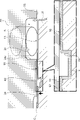
実施例1に係るスプール弁につき、図1~図4を参照して説明する。以下、図1の正面から見て左右をスプール弁の左右として説明する。詳しくは、ソレノイド80が配置される紙面右側をスプール弁の右側、コイルスプリング90が配置される紙面左側をスプール弁の左側として説明する。尚、窪みについては、ドット状のテクスチャを付して図示することもある。
図1を参照して、スプール弁1は、油の流量を調整するスプールタイプのソレノイドバルブである。尚、スプール弁1により流量等を調整する流体は油に限られない。
図1に示されるように、スプール弁1は、スプール10と、スリーブ20と、ソレノイド80と、コイルスプリング90と、から主に構成されている。スプール10は、金属材料または樹脂材料により形成されている。スリーブ20には、スプール10が軸方向に移動可能に挿入されている。ソレノイド80は、スリーブ20に接続されスプール10に開弁方向への駆動力を及ぼすようになっている。コイルスプリング90は、スリーブ20内に配置されスプール10に閉弁方向への付勢力を及ぼしている。
ソレノイド80は、ケーシング81と、固定鉄心としてのステータ82と、ロッド83と、可動鉄心84と、励磁用のコイル86と、から主に構成されている。ステータ82は、ケーシング81の一部である。ロッド83は、ケーシング81に挿通され軸方向に往復動自在に配置されている。可動鉄心84は、ケーシング81に挿通されロッド83に駆動力を伝達するようになっている。コイル86は、ケーシング81の外側にボビンを介して巻き付けられている。
ケーシング81の左端部には、左向きT字状のステータ82が配置されている。ステータ82の左端部中央には、軸方向右方に凹む凹部が形成されている。この凹部には、スリーブ20の右端部が圧入・固定されている。
スリーブ20は、径方向中央に軸方向に貫通する貫通孔21が形成された、段付き円筒状に形成されている。
また、スリーブ20には、軸方向右方から順に、排出ポート22、出口ポート23、入口ポート24、フィードバックポート25が形成されている。排出ポート22は、オイルリザーバRと連通している。出口ポート23は負荷Tに連通している。入口ポート24は、油圧ポンプPに連通している。フィードバックポート25は、出口ポート23に連通している。各ポート22~25は、貫通孔21に対して主に径方向に延在している流路である。
また、スリーブ20の内径側には、第1内壁31と、第2内壁32と、第3内壁33と、第4内壁34と、第5内壁35が形成されている。第1内壁31は、排出ポート22の軸方向右方側にて内径側に突出し環状に形成されている。第2内壁32は、排出ポート22の軸方向左方側にて内径側に突出し環状に形成されている。第3内壁33は、出口ポート23の軸方向左方側にて内径側に突出し環状に形成されている。第4内壁34は、入口ポート24の軸方向左方側にて内径側に突出し環状に形成されている。第5内壁35は、フィードバックポート25の軸方向左方側にて内径側に突出し環状に形成されている。
また、スリーブ20の内径側には、凹部24aが形成されている。凹部24aは、第3内壁33および第4内壁34の間に径方向外径側に凹み環状に形成されている。この凹部24aによって画成されている環状空間Sは、入口ポート24および貫通孔21に連通している。本実施例における貫通孔21は、内壁31~35によって画成される円柱状の孔である。
また、スリーブ20には、第1内壁31の軸方向右方側にスリーブ20外の外空間Aに連通する呼吸路26が形成されている。
また、スリーブ20の左端部には、コイルスプリング90を保持するリテーナ27がカシメ固定されている。また、リテーナ27の底部には、外空間Aに連通する呼吸路28が形成されている。
ソレノイド80とスプール10との間の空間の容積、スプール10とリテーナ27との間の空間の容積は、スプール10の移動によって変化するようになっている。なお、呼吸路26,28はスリーブ20外の外空間Aに連通しているので容積の変化に応じて外空間Aから流体が流出入することから、各空間の圧力が略同一に保たれるようになっている。
スプール10は、外径側段付き円柱状に形成されている。スプール10の外周面には、摺動性の良化や、腐食防止等を目的としてメッキ、DLC(diamond‐like carbon)、二硫化モリブデン等によるコーティングが施されてコーティング層C(図3参照)が形成されている。尚、図3,4では、説明の都合上、コーティング層Cを誇張して図示している。また、スリーブ20の内周面にもコーティング層Cが形成されていてもよく、スプール10、スリーブ20共にコーティングされていなくともよい。
スプール10には、軸方向右方から順に、第1ランド11と、第1小径部12と、第2ランド13と、第2小径部14と、第3ランド15と、第3小径部16が形成されている。第1小径部12は、第1ランド11よりも小径に形成されている。第2ランド13は、第1小径部12よりも大径に形成されている。第2小径部14は、第2ランド13よりも小径に形成されている。第3ランド15は、第2小径部14よりも大径に形成されている。第3小径部16は、第3ランド15よりも小径に形成されている。
図1,図2を参照して、スプール10がスリーブ20の貫通孔21に挿通された状態において、第1ランド11は第1内壁31および第2内壁32に摺接可能に配置されている。第2ランド13は第3内壁33および第4内壁34に摺接可能に配置されている。第3ランド15は第5内壁35に摺接可能に配置されている。
図1~図3を参照して、第2ランド13には、環状の貯留溝40と、あみだくじ(すなわちladder lottery)状の窪み50が形成されている。貯留溝40は、コーティング前の第2ランド13が周方向に亘って環状に切削された後、その表面がコーティングされて形成された溝である。また、窪み50は、スプール10のコーティング層C(図3参照)の周方向に亘って形成された窪みである。
図1,図2を参照して、窪み50についてより詳しくは、軸方向に直線状に延びる複数の軸窪部51と、周方向に直線状に延びる複数の周窪部52から構成されている。
各軸窪部51は、周方向所定間隔置きに配置されている。また、各軸窪部51の軸方向両端部は、第2ランド13における軸方向右端および同左端、言い換えれば出口ポート23側の端13Rおよびフィードバックポート25側の端13Lから離間し、軸方向に閉塞されている。
また、軸窪部51は、その軸方向左端部に形成されている貯留溝40に連通している。より詳しくは、入口ポート24側から貯留溝40に連通している部分と、貯留溝40から第2ランド13の端13L側に連通している部分がある。
各周窪部52は、軸方向に所定間隔置きに配置されている。また、周方向に隣接する周窪部52同士は軸方向位置が異なり、周方向に一つ離れた周窪部52同士は軸方向位置が同じとなっている。つまり、窪み50は周方向全域に亘って特定のパターンが等配に設けられている。
図3に示されるように、貯留溝40の深さ寸法L1は、軸窪部51の深さ寸法L2よりも十分に深くなっている(L1>L2)。具体的には、貯留溝40の深さ寸法L1は100μmに形成されており、軸窪部51の深さ寸法L2は5μmに形成されている。また、周窪部52の深さ寸法は軸窪部51の深さ寸法と略同一である。尚、貯留溝40の深さ寸法が軸窪部51の深さ寸法よりも深く形成されていれば、貯留溝40及び軸窪部51の深さ寸法は自由に変更できる。好ましくは、深さ寸法L1は深さ寸法L2の5倍以上である。
また、図1,図2に示されるように、第2ランド13には、隣り合う一対の軸窪部51と一対の周窪部52、または隣り合う一対の軸窪部51と一の周窪部52によって囲まれた荷重受部13aが多数形成されている。これら荷重受部13aはスリーブ20の内壁33,34に摺動する。
次に、スプール弁1の動作について、図1~図4を参照して説明する。
図1に示されるように、ソレノイド80の非通電時においては、コイルスプリング90の付勢力によってスプール10が軸方向右方へと移動されて第2ランド13とスリーブ20の内壁33,34の間が密封されている。これにより、入口ポート24から出口ポート23への流体の流入が規制されている閉弁状態となっている。すなわち、スプール弁1はノーマルクローズである。尚、スプール弁1はノーマルオープンであってもよい。
閉弁状態では、第1ランド11と第2内壁32が離間しており、排出ポート22と出口ポート23が連通状態となっている。
また、閉弁状態では、窪み50の軸方向中央部分が環状空間Sに、中央部分よりも軸方向右側が第3内壁33に、中央部分よりも軸方向左側が第4内壁34にそれぞれ面している。中央部分は、環状空間Sの流体に曝されているため、軸窪部51や周窪部52を伝ってスリーブ20の内壁33,34に面している部分にも流体が供給されている、すなわち入口ポート24から軸方向に離れた位置まで流体が供給されている。
加えて、窪み50は周方向に亘って形成されているため、周方向の位置を問わず流体が供給されている。
また、窪み50の軸方向両端部は、第2ランド13の端13Rまたは端13Lの近傍で閉塞している。また、該箇所はスリーブ20の内壁33,34に面しているため、窪み50内の流体が第2ランド13の外に漏れることが防止されている。
また、貯留溝40は、窪み50に連通しているため、入口ポート24から窪み50を通じて流体が供給されている。
また、第2ランド13における端13Rおよび端13Lに作用する圧力は、出口ポート23にフィードバックポート25が連通しているため略同一となっている。
次いで、通電状態について説明する。スプール弁1は、ソレノイド80に電流が印加されることにより発生する電磁力がコイルスプリング90の付勢力を上回ると、可動鉄心84がステータ82側、すなわち軸方向左側に引き寄せられる。また、可動鉄心84に固定されたロッド83が軸方向左方へ一体に移動することにより、スプール10が軸方向左方へ移動する。
入口ポート24と対向する第2ランド13に窪み50が形成されており、上述したように閉弁状態において窪み50全体に流体が供給されている。これにより、流体の影響を受けやすい第2ランド13と第3内壁33との良好な潤滑状態が保たれる。また、第2ランド13と内壁33,34との良好な潤滑状態が保たれる。よって、スプール10の移動に必要な駆動力が低減され、安定して軸方向に移動させることができる。
また、窪み50には、入口ポート24から流入する流体ばかりでなく、貯留溝40からもスプール10の移動により窪み50内の流体が移動することに伴って流体が供給されるため、より確実に流体を供給することができる。
また、スプール10の移動において、窪み50に流入した流体の圧力によって浮力を生じさせる場合もある。
また、軸窪部51、周窪部52には、スプール10の移動によって他の軸窪部51、周窪部52から荷重受部13a上に移動した流体も流入するため、枯渇し難くなっている。
これらにより、内壁33,34と第2ランド13との間に液膜が形成されるため、内壁33,34と第2ランド13との間で強い摩擦力が生じにくくなっている。
図2,図4を参照して、閉弁状態からスプール10の軸方向左方へ移動すると、第2ランド13と第3内壁33が離間し、入口ポート24から出口ポート23に流体が流入する開弁状態となる。その後、印加される電流が増すごとにスプール10は軸方向左側へと移動し、図2では弁開度が最大となっている。
開弁状態では、窪み50の軸方向右半分が環状空間Sに、軸方向右半分よりも左側に位置する軸方向左半分が第4内壁34にそれぞれ面している。これにより、軸方向右半分は、環状空間Sの流体に曝されているため、軸窪部51や周窪部52を伝ってスリーブ20の第4内壁34に面している軸方向左半分にも流体が供給されている、すなわち入口ポート24から軸方向に離れ第4内壁34に面する位置まで流体が供給されている。
また、貯留溝40は、非通電時であっても(図1参照)、通電時かつ弁開度が最大であっても(図2参照)、第4内壁34に面しており、フィードバックポート25に直接連通していないため、貯留溝40内の流体が枯渇することが防止されている。
次に、閉弁状態から開弁状態への切り替わりについて説明する。
閉弁状態から開弁状態への切り替わりにあたって、図4において白抜き矢印で示すように過渡的にスプール10を径方向に移動させる力が作用し、図4において黒塗り矢印で示すように第2ランド13が第4内壁34に押し付けられることがある。このような場合にも、スプール弁1は、窪み50には流体が保持されていることから、第2ランド13と内壁33,34との良好な潤滑状態が保たれる。よって、安定してスプール10を軸方向左方に移動させることができる。
また、窪み50は、周方向に亘って形成されているため、周方向の位置を問わずに第2ランド13と第4内壁34との潤滑状態を良好とすることができる。
また、スプール10は、第2ランド13に形成されている複数の荷重受部13aによってスリーブ20の内壁33,34に支持されるため、大きく傾動または撓み変形することが抑止されている。
また、窪み50の軸方向左端部は、スプール10が軸方向左方に移動してフィードバックポート25に連通することで、フィードバックポート25から流体の供給を受けることが可能となっている。すなわち、窪み50が軸方向に延びているため、フィードバックポートと連通しやすく、流体の枯渇を防止することができる。
また、窪み50は、周方向において周窪部52が不連続に配置されているため、周方向に亘って連続している構成と比較して、流体が直線状に移動し難いことから、周方向全域において流体を保持しやすくなっている。
また、閉弁状態における環状空間Sは、第3内壁33および第4内壁34の間の凹部24aと、第2ランド13によって画成された環状の空間となっているため、閉弁状態から開弁状態への切り替わり時に、流体から作用する力は周方向に分散されやすく過渡的にスプール10を径方向に移動させる力が軽減されるようになっている。これにより、第2ランド13がスリーブ20の内壁33,34にかじり難くなり、より安定して第2ランド13と内壁33,34との良好な潤滑状態を保つことができる。
次に、実施例2に係るスプール弁について、図5を参照して説明する。尚、前記実施例1と同一構成で重複する構成の説明を省略する。
図5に示されるように、スプール弁101は、スプール110の第2ランド113に窪み150が形成されている。
窪み150は、周方向を基準とし位相が180度ずれた同振幅・同周期三角波状の三角波状窪部151,152から構成されている。また、周方向複数箇所で各々の窪部151,152が連通している。また、各三角波状窪部151,152の軸方向両端部が、第2ランド113の端113R,113Lから離間し、軸方向に閉塞されている。
これらのように、窪み150は一条のダイアゴナルチェック状に形成されている。
また、三角波状窪部151および三角波状窪部152の深さ寸法は、前記実施例1における軸窪部51および周窪部52それぞれの深さ寸法L2と略同一である。
第2ランド113には、三角波状窪部151と三角波状窪部152によって囲まれた荷重受部113aが多数形成されている。これら荷重受部113aはスリーブ20の内壁33,34に摺動する。
これにより、閉弁状態において、窪み150には流体が保持されているばかりでなく、入口ポート24から供給されていることから、第2ランド113と内壁33,34との良好な潤滑状態が保たれるため、安定してスプール110を軸方向左方に移動させることができる。
また、図5(b)に示されるように、窪み150の軸方向左端部は、スプール110が軸方向左方に移動してフィードバックポート25に連通することで、フィードバックポート25から流体の供給を受けることが可能となっている。
また、スプール110の移動において、窪み150に流入した流体の圧力によって浮力を生じさせる場合もある。
また、三角波状窪部151、三角波状窪部152には、スプール110の移動によって他の三角波状窪部151、三角波状窪部152から荷重受部113a上に移動した流体も流入するため、より枯渇し難くなっている。
これらにより、内壁33,34と第2ランド113との間に液膜が形成されるため、内壁33,34と第2ランド113との間で強い摩擦力が生じにくくなっている。
次に、実施例3に係るスプール弁について、図6を参照して説明する。尚、前記実施例1,2と同一構成で重複する構成の説明を省略する。
図6に示されるように、スプール弁201には、スプール210の第2ランド213に、球の一部形状に凹む窪みであるディンプル250が複数形成されており、各ディンプル250の周囲には荷重受部213aが形成されている。また、各ディンプル250は、第2ランド213の端213L,213Rから離間している。尚、ディンプル250は、円柱状に凹んでいてもよく、多角柱状に凹んでいてもよく、球の一部形状に限定されるものではない。
また、ディンプル250の最も深い部分の深さ寸法は、前記実施例1における軸窪部51および周窪部52それぞれの深さ寸法L2と略同一である。
これにより、閉弁状態において環状空間Sに面している各ディンプル250には、流体が供給されており、閉弁状態において、ディンプル250には流体が保持されている。よって、第2ランド213と内壁33,34との良好な潤滑状態が保たれるため、安定してスプール210を軸方向左方に移動させることができる。
また、図6(b)に示されるように、軸方向左側に位置する各ディンプル250は、スプール210が軸方向左方に移動してフィードバックポート25に連通することで、フィードバックポート25から流体の供給を受けることが可能となっている。
また、スプール210の移動において、ディンプル250に流入した流体の圧力によって浮力を生じさせる場合もある。
また、閉弁状態においても、開弁状態においても、入口ポート24およびフィードバックポート25に面しない各ディンプル250については、スプール210の移動によって他のディンプル250から荷重受部213a上に移動した流体が流入することで供給されるため、枯渇し難くなっている。
これらにより、内壁33,34と第2ランド213との間に液膜が形成されるため、内壁33,34と第2ランド213との間で強い摩擦力が生じにくくなっている。
次に、実施例4に係るスプール弁について、図7を参照して説明する。尚、前記実施例1~3と同一構成で重複する構成の説明を省略する。
図7を参照して、スプール弁301には、スプール310の第2ランド313には窪みが形成されておらず平滑な外周面をなしている。一方、スリーブ120には、内壁133,134のコーティング層Cに複数の軸窪部351および複数の周窪部352から構成され、凹部24aに連通している窪み350が形成されている。
また、軸窪部351および周窪部352の深さ寸法は、前記実施例1における軸窪部51および周窪部52それぞれの深さ寸法L2と略同一である。
また、内壁133,134には、隣り合う一対の軸窪部351と一対の周窪部352、または隣り合う一対の軸窪部351と一の周窪部352によって囲まれた荷重受部133a,134aが多数形成されている。これら荷重受部133a,134aにはスプール310の第2ランド313が摺接する。
これにより、閉弁状態において、窪み350には流体が保持されているばかりでなく、入口ポート24から供給されていることから、第2ランド313と内壁133,134との良好な潤滑状態が保たれる。よって、安定してスプール310を軸方向左方に移動させることができる。
また、窪み350の軸方向両端部は、閉弁状態において第2ランド313の端313L,313Rから離間しており、出口ポート23およびフィードバックポート25に連通していないため、窪み350内の流体が第2ランド313の外に漏れることが防止されている。
また、スプール310の移動において、窪み350に流入した流体の圧力によって浮力を生じさせる場合もある。
また、軸窪部351、周窪部352には、スプール310の移動によって他の軸窪部351、周窪部352から荷重受部133a,134a上に移動した流体も流入するため、より枯渇し難くなっている。
これらにより、内壁133,134と第2ランド313との間に流体による液膜が形成されるため、内壁133,134と第2ランド313との間で強い摩擦力が生じにくくなっている。
また、スプール310は、内壁133,134に形成されている複数の荷重受部133a,134aによって支持されるため、大きく傾動または撓み変形することが抑止されている。
以上、本発明の実施例を図面により説明してきたが、具体的な構成はこれら実施例に限られるものではなく、本発明の要旨を逸脱しない範囲における変更や追加があっても本発明に含まれる。
例えば、前記実施例では、スプール弁は、駆動方法がソレノイド式である構成として説明したが、これに限らず、手動式、油圧式等他の駆動方法であってもよい。
また、窪みは、周方向に亘って形成されているあみだくじ状、ダイアゴナルチェック状、ディンプルである構成として説明したが、これに限らず、周方向に亘って形成されている格子状(図8(a)参照)、ダイアゴナルストライプ状(図8(b)参照)等であってもよい。また、軸窪部から周方向に延びるL字状部、逆L字状部を複数有する窪みが周方向に所定間隔置きに複数配置されてもよい(図8(c)参照)。また、周方向に連続する環状の窪みのみが軸方向に複数離間配置されていてもよい(図8(d)参照)。また、スプールが開弁方向へ移動するにあたってスリーブの内壁と接触する部分にのみ窪みが形成されていてもよい(図8(e)参照)。また、実施例1~3や図8の各形状を組合わせてもよく、適宜変更されてもよい。
また、窪みは閉弁状態において入口ポートに面する第2ランドまたは、入口ポートに連通するスリーブの内壁に形成されている構成として説明したが、これに限らず、他のポートに面するランドまたは他のポートに連通するスリーブの内壁に形成されていてもよい。
また、窪みは、第2ランドまたは第3,第4内壁に形成されている構成として説明したが、これに限らず、両方に形成されていてもよい。
また、第2ランドは、入口ポートが連通する環状空間に面している構成として説明したが、これに限らず、入口ポートに直接面していてもよい。同様に、スリーブの内壁に形成された窪みは、直接入口ポートに連通していてもよい。
また、窪みは、コーティング層に形成されている構成として説明したが、これに限らず、スプールやスリーブに直接形成されていてもよい。
また、荷重受部は、複数形成されていても、一つだけ形成されていてもよい。
また、貯留溝は、コーティング前に切削された後、コーティングされて形成されている構成として説明したが、これに限らず、切削後コーティングされていなくともよい。
また、ランドに環状の貯留溝が形成されている構成として説明したが、これに限らず、貯留溝は形成されていなくてもよい。
また、各ポートは、貫通孔に対して主に径方向に延在している流路である構成として説明したが、これに限らず、貫通孔に対して軸方向に連通していてもよい。すなわち、本発明では、ポートの連通方向に限らず、ランドが内壁に摺動可能に設けられており、ランドと内壁によって弁開度が調節される構成のものをスプール弁とする。
1 スプール弁
10 スプール
13 第2ランド
13L,13R 端(隣接するポート側の端)
13a 荷重受部
20 スリーブ
22 排出ポート
23 出口ポート
24 入口ポート
25 フィードバックポート
33 第3内壁
34 第4内壁
40 貯留溝
50 窪み
51 軸窪部
52 周窪部
101,201 スプール弁
110~310 スプール
113~313 第2ランド
113L~313R 端(隣接するポート側の端)
113a,213a 荷重受部
120 スリーブ
133 第3内壁
133a,134a 荷重受部
134 第4内壁
150~350 窪み
151,152 三角波状窪部
250 ディンプル
351 軸窪部
352 周窪部
L1 深さ寸法
L2 深さ寸法
S 環状空間
10 スプール
13 第2ランド
13L,13R 端(隣接するポート側の端)
13a 荷重受部
20 スリーブ
22 排出ポート
23 出口ポート
24 入口ポート
25 フィードバックポート
33 第3内壁
34 第4内壁
40 貯留溝
50 窪み
51 軸窪部
52 周窪部
101,201 スプール弁
110~310 スプール
113~313 第2ランド
113L~313R 端(隣接するポート側の端)
113a,213a 荷重受部
120 スリーブ
133 第3内壁
133a,134a 荷重受部
134 第4内壁
150~350 窪み
151,152 三角波状窪部
250 ディンプル
351 軸窪部
352 周窪部
L1 深さ寸法
L2 深さ寸法
S 環状空間
Claims (7)
- 複数のポートが形成されたスリーブと、前記スリーブ内に配置され、ランドが前記スリーブの内壁に摺接可能に形成されたスプールと、を備えたスプール弁であって、
前記ランドおよび当該ランドが摺接する前記スリーブの内壁の少なくともいずれか一方には、周方向全域に亘って窪みが形成されているスプール弁。 - 前記窪みは、複数の窪部から形成されており、
前記ランドおよび当該ランドが摺接する前記スリーブの内壁の少なくともいずれか一方は、隣り合う前記窪部の間に前記スリーブの内壁または前記ランドに摺接する荷重受部を有している請求項1に記載のスプール弁。 - 前記窪みは、軸方向に延びている請求項1または2に記載のスプール弁。
- 前記ランドは、前記スリーブに流体が流入する入口ポートと対向する請求項1ないし3のいずれかに記載のスプール弁。
- 前記窪みは、前記入口ポートが連通する環状空間に連通している請求項4に記載のスプール弁。
- 前記窪みは、流体が貯留される貯留溝に連通している請求項1ないし5のいずれかに記載のスプール弁。
- 前記窪みは、前記ランドおよび当該ランドが摺接する前記スリーブの内壁の少なくともいずれか一方において、前記窪みが形成された箇所の軸方向両側の端から離間している請求項1ないし6のいずれかに記載のスプール弁。
Priority Applications (4)
| Application Number | Priority Date | Filing Date | Title |
|---|---|---|---|
| EP21889068.9A EP4242500A4 (en) | 2020-11-05 | 2021-10-25 | CYLINDRICAL DRAWER DISTRIBUTOR |
| CN202180074947.5A CN116420040A (zh) | 2020-11-05 | 2021-10-25 | 滑阀 |
| US18/034,663 US12188573B2 (en) | 2020-11-05 | 2021-10-25 | Spool valve |
| JP2022560720A JPWO2022097515A1 (ja) | 2020-11-05 | 2021-10-25 |
Applications Claiming Priority (2)
| Application Number | Priority Date | Filing Date | Title |
|---|---|---|---|
| JP2020185375 | 2020-11-05 | ||
| JP2020-185375 | 2020-11-05 |
Publications (1)
| Publication Number | Publication Date |
|---|---|
| WO2022097515A1 true WO2022097515A1 (ja) | 2022-05-12 |
Family
ID=81457825
Family Applications (1)
| Application Number | Title | Priority Date | Filing Date |
|---|---|---|---|
| PCT/JP2021/039230 Ceased WO2022097515A1 (ja) | 2020-11-05 | 2021-10-25 | スプール弁 |
Country Status (5)
| Country | Link |
|---|---|
| US (1) | US12188573B2 (ja) |
| EP (1) | EP4242500A4 (ja) |
| JP (1) | JPWO2022097515A1 (ja) |
| CN (1) | CN116420040A (ja) |
| WO (1) | WO2022097515A1 (ja) |
Families Citing this family (1)
| Publication number | Priority date | Publication date | Assignee | Title |
|---|---|---|---|---|
| EP4261441A1 (en) * | 2022-04-13 | 2023-10-18 | Sandvik Mining and Construction Oy | Control valve, impact device and method |
Citations (5)
| Publication number | Priority date | Publication date | Assignee | Title |
|---|---|---|---|---|
| US4593719A (en) * | 1984-11-30 | 1986-06-10 | Leonard Willie B | Spool valve |
| JP2001263529A (ja) * | 2000-03-16 | 2001-09-26 | Mitsubishi Electric Corp | 電磁弁 |
| WO2002018828A1 (en) * | 2000-08-28 | 2002-03-07 | Nok Corporation | Solenoid valve |
| JP2009115289A (ja) * | 2007-11-09 | 2009-05-28 | Denso Corp | スプール弁 |
| JP2014163478A (ja) | 2013-02-27 | 2014-09-08 | Keihin Corp | リニアソレノイドバルブ |
Family Cites Families (11)
| Publication number | Priority date | Publication date | Assignee | Title |
|---|---|---|---|---|
| JP2002074000A (ja) | 2000-08-28 | 2002-03-12 | Sanwa Bank Ltd | 情報通信ネットワークを介した資金決済処理支援システム |
| JP4457827B2 (ja) * | 2004-09-24 | 2010-04-28 | 株式会社デンソー | 電磁弁 |
| JP4572776B2 (ja) * | 2005-08-24 | 2010-11-04 | 株式会社デンソー | 流量制御弁 |
| EP3158207B1 (en) * | 2014-06-23 | 2018-10-17 | Parker-Hannifin Corp | Oil exchange in hydraulically operated and electro-hydraulically operated hydraulic valves |
| US10156246B2 (en) * | 2014-09-29 | 2018-12-18 | Parker-Hannifin Corporation | Directional control valve |
| US10494791B2 (en) * | 2015-01-08 | 2019-12-03 | Volvo Construction Equipment Ab | Flow control valve for construction machine |
| CA2939372A1 (en) * | 2015-08-20 | 2017-02-20 | Parker-Hannifin Corporation | Spool valve with special metering configuration for hydraulic valve main control speed |
| DE112016000086B4 (de) * | 2016-05-31 | 2018-12-27 | Komatsu Ltd. | Schieberventil und arbeitsfahrzeug |
| JP6652008B2 (ja) * | 2016-07-21 | 2020-02-19 | 株式会社デンソー | スプール弁 |
| JP6955405B2 (ja) * | 2017-09-12 | 2021-10-27 | 川崎重工業株式会社 | スプール弁装置、及びスプール弁 |
| US11448313B2 (en) * | 2017-11-02 | 2022-09-20 | Superior Transmission Parts, Inc. | Pressure regulator valve |
-
2021
- 2021-10-25 JP JP2022560720A patent/JPWO2022097515A1/ja active Pending
- 2021-10-25 EP EP21889068.9A patent/EP4242500A4/en active Pending
- 2021-10-25 CN CN202180074947.5A patent/CN116420040A/zh active Pending
- 2021-10-25 US US18/034,663 patent/US12188573B2/en active Active
- 2021-10-25 WO PCT/JP2021/039230 patent/WO2022097515A1/ja not_active Ceased
Patent Citations (5)
| Publication number | Priority date | Publication date | Assignee | Title |
|---|---|---|---|---|
| US4593719A (en) * | 1984-11-30 | 1986-06-10 | Leonard Willie B | Spool valve |
| JP2001263529A (ja) * | 2000-03-16 | 2001-09-26 | Mitsubishi Electric Corp | 電磁弁 |
| WO2002018828A1 (en) * | 2000-08-28 | 2002-03-07 | Nok Corporation | Solenoid valve |
| JP2009115289A (ja) * | 2007-11-09 | 2009-05-28 | Denso Corp | スプール弁 |
| JP2014163478A (ja) | 2013-02-27 | 2014-09-08 | Keihin Corp | リニアソレノイドバルブ |
Non-Patent Citations (1)
| Title |
|---|
| See also references of EP4242500A4 |
Also Published As
| Publication number | Publication date |
|---|---|
| JPWO2022097515A1 (ja) | 2022-05-12 |
| US20230392697A1 (en) | 2023-12-07 |
| US12188573B2 (en) | 2025-01-07 |
| EP4242500A4 (en) | 2024-10-09 |
| EP4242500A1 (en) | 2023-09-13 |
| CN116420040A (zh) | 2023-07-11 |
Similar Documents
| Publication | Publication Date | Title |
|---|---|---|
| JP7266415B2 (ja) | ガス用電磁弁 | |
| JP5686201B2 (ja) | 電磁式リニア弁 | |
| JP2013100915A (ja) | 電磁弁 | |
| JP6094309B2 (ja) | ソレノイド駆動装置 | |
| JP5560425B2 (ja) | 電磁弁用ソレノイド | |
| JP5916450B2 (ja) | 切換バルブ | |
| JP6991890B2 (ja) | スプールバルブ | |
| US9163745B2 (en) | Solenoid valve | |
| JP6245632B2 (ja) | リニアソレノイドバルブ | |
| US12188573B2 (en) | Spool valve | |
| EP1420321A2 (en) | Dual proportional pressure reducing valve | |
| JP7171509B2 (ja) | ソレノイドバルブ | |
| WO2020226101A1 (ja) | ソレノイドバルブ | |
| KR101605710B1 (ko) | 디텐트 기구 부착 더블 솔레노이드 밸브 | |
| JP2019190635A (ja) | 電磁比例弁付きキャップ | |
| KR102086109B1 (ko) | 개선된 형상의 랜드부를 갖는 스풀을 구비한 비례감압밸브 | |
| CN111051707B (zh) | 滑阀 | |
| JP2005133880A (ja) | 電磁弁 | |
| KR102501556B1 (ko) | 흐름 제어 밸브 | |
| JP7463355B2 (ja) | ソレノイドバルブ | |
| JP7152227B2 (ja) | ソレノイドバルブ | |
| JP6888451B2 (ja) | 電磁弁 | |
| CN113302424B (zh) | 气体用电磁阀 | |
| JP5982832B2 (ja) | ソレノイドバルブ | |
| JP4199698B2 (ja) | 電磁弁 |
Legal Events
| Date | Code | Title | Description |
|---|---|---|---|
| 121 | Ep: the epo has been informed by wipo that ep was designated in this application |
Ref document number: 21889068 Country of ref document: EP Kind code of ref document: A1 |
|
| ENP | Entry into the national phase |
Ref document number: 2022560720 Country of ref document: JP Kind code of ref document: A |
|
| NENP | Non-entry into the national phase |
Ref country code: DE |
|
| ENP | Entry into the national phase |
Ref document number: 2021889068 Country of ref document: EP Effective date: 20230605 |