WO2022106231A1 - Procede de fabrication d'une canalisation thermoplastique renforcee comportant une portion cintree - Google Patents
Procede de fabrication d'une canalisation thermoplastique renforcee comportant une portion cintree Download PDFInfo
- Publication number
- WO2022106231A1 WO2022106231A1 PCT/EP2021/080892 EP2021080892W WO2022106231A1 WO 2022106231 A1 WO2022106231 A1 WO 2022106231A1 EP 2021080892 W EP2021080892 W EP 2021080892W WO 2022106231 A1 WO2022106231 A1 WO 2022106231A1
- Authority
- WO
- WIPO (PCT)
- Prior art keywords
- tube
- reinforced
- reinforcing
- pipe
- portions
- Prior art date
- Legal status (The legal status is an assumption and is not a legal conclusion. Google has not performed a legal analysis and makes no representation as to the accuracy of the status listed.)
- Ceased
Links
Images





Classifications
-
- F—MECHANICAL ENGINEERING; LIGHTING; HEATING; WEAPONS; BLASTING
- F16—ENGINEERING ELEMENTS AND UNITS; GENERAL MEASURES FOR PRODUCING AND MAINTAINING EFFECTIVE FUNCTIONING OF MACHINES OR INSTALLATIONS; THERMAL INSULATION IN GENERAL
- F16L—PIPES; JOINTS OR FITTINGS FOR PIPES; SUPPORTS FOR PIPES, CABLES OR PROTECTIVE TUBING; MEANS FOR THERMAL INSULATION IN GENERAL
- F16L9/00—Rigid pipes
- F16L9/12—Rigid pipes of plastics with or without reinforcement
- F16L9/127—Rigid pipes of plastics with or without reinforcement the walls consisting of a single layer
- F16L9/128—Reinforced pipes
-
- B—PERFORMING OPERATIONS; TRANSPORTING
- B29—WORKING OF PLASTICS; WORKING OF SUBSTANCES IN A PLASTIC STATE IN GENERAL
- B29C—SHAPING OR JOINING OF PLASTICS; SHAPING OF MATERIAL IN A PLASTIC STATE, NOT OTHERWISE PROVIDED FOR; AFTER-TREATMENT OF THE SHAPED PRODUCTS, e.g. REPAIRING
- B29C53/00—Shaping by bending, folding, twisting, straightening or flattening; Apparatus therefor
- B29C53/02—Bending or folding
- B29C53/08—Bending or folding of tubes or other profiled members
- B29C53/083—Bending or folding of tubes or other profiled members bending longitudinally, i.e. modifying the curvature of the tube axis
-
- B—PERFORMING OPERATIONS; TRANSPORTING
- B29—WORKING OF PLASTICS; WORKING OF SUBSTANCES IN A PLASTIC STATE IN GENERAL
- B29C—SHAPING OR JOINING OF PLASTICS; SHAPING OF MATERIAL IN A PLASTIC STATE, NOT OTHERWISE PROVIDED FOR; AFTER-TREATMENT OF THE SHAPED PRODUCTS, e.g. REPAIRING
- B29C70/00—Shaping composites, i.e. plastics material comprising reinforcements, fillers or preformed parts, e.g. inserts
- B29C70/04—Shaping composites, i.e. plastics material comprising reinforcements, fillers or preformed parts, e.g. inserts comprising reinforcements only, e.g. self-reinforcing plastics
- B29C70/06—Fibrous reinforcements only
- B29C70/10—Fibrous reinforcements only characterised by the structure of fibrous reinforcements, e.g. hollow fibres
- B29C70/16—Fibrous reinforcements only characterised by the structure of fibrous reinforcements, e.g. hollow fibres using fibres of substantial or continuous length
- B29C70/20—Fibrous reinforcements only characterised by the structure of fibrous reinforcements, e.g. hollow fibres using fibres of substantial or continuous length oriented in a single direction, e.g. roofing or other parallel fibres
-
- B—PERFORMING OPERATIONS; TRANSPORTING
- B29—WORKING OF PLASTICS; WORKING OF SUBSTANCES IN A PLASTIC STATE IN GENERAL
- B29D—PRODUCING PARTICULAR ARTICLES FROM PLASTICS OR FROM SUBSTANCES IN A PLASTIC STATE
- B29D23/00—Producing tubular articles
- B29D23/001—Pipes; Pipe joints
- B29D23/003—Pipe joints, e.g. straight joints
- B29D23/006—Elbows
-
- F—MECHANICAL ENGINEERING; LIGHTING; HEATING; WEAPONS; BLASTING
- F16—ENGINEERING ELEMENTS AND UNITS; GENERAL MEASURES FOR PRODUCING AND MAINTAINING EFFECTIVE FUNCTIONING OF MACHINES OR INSTALLATIONS; THERMAL INSULATION IN GENERAL
- F16L—PIPES; JOINTS OR FITTINGS FOR PIPES; SUPPORTS FOR PIPES, CABLES OR PROTECTIVE TUBING; MEANS FOR THERMAL INSULATION IN GENERAL
- F16L43/00—Bends; Siphons
- F16L43/008—Bends; Siphons made from plastic material
-
- F—MECHANICAL ENGINEERING; LIGHTING; HEATING; WEAPONS; BLASTING
- F16—ENGINEERING ELEMENTS AND UNITS; GENERAL MEASURES FOR PRODUCING AND MAINTAINING EFFECTIVE FUNCTIONING OF MACHINES OR INSTALLATIONS; THERMAL INSULATION IN GENERAL
- F16L—PIPES; JOINTS OR FITTINGS FOR PIPES; SUPPORTS FOR PIPES, CABLES OR PROTECTIVE TUBING; MEANS FOR THERMAL INSULATION IN GENERAL
- F16L9/00—Rigid pipes
- F16L9/12—Rigid pipes of plastics with or without reinforcement
-
- F—MECHANICAL ENGINEERING; LIGHTING; HEATING; WEAPONS; BLASTING
- F16—ENGINEERING ELEMENTS AND UNITS; GENERAL MEASURES FOR PRODUCING AND MAINTAINING EFFECTIVE FUNCTIONING OF MACHINES OR INSTALLATIONS; THERMAL INSULATION IN GENERAL
- F16L—PIPES; JOINTS OR FITTINGS FOR PIPES; SUPPORTS FOR PIPES, CABLES OR PROTECTIVE TUBING; MEANS FOR THERMAL INSULATION IN GENERAL
- F16L9/00—Rigid pipes
- F16L9/12—Rigid pipes of plastics with or without reinforcement
- F16L9/133—Rigid pipes of plastics with or without reinforcement the walls consisting of two layers
-
- F—MECHANICAL ENGINEERING; LIGHTING; HEATING; WEAPONS; BLASTING
- F16—ENGINEERING ELEMENTS AND UNITS; GENERAL MEASURES FOR PRODUCING AND MAINTAINING EFFECTIVE FUNCTIONING OF MACHINES OR INSTALLATIONS; THERMAL INSULATION IN GENERAL
- F16L—PIPES; JOINTS OR FITTINGS FOR PIPES; SUPPORTS FOR PIPES, CABLES OR PROTECTIVE TUBING; MEANS FOR THERMAL INSULATION IN GENERAL
- F16L9/00—Rigid pipes
- F16L9/14—Compound tubes, i.e. made of materials not wholly covered by any one of the preceding groups
-
- B—PERFORMING OPERATIONS; TRANSPORTING
- B29—WORKING OF PLASTICS; WORKING OF SUBSTANCES IN A PLASTIC STATE IN GENERAL
- B29K—INDEXING SCHEME ASSOCIATED WITH SUBCLASSES B29B, B29C OR B29D, RELATING TO MOULDING MATERIALS OR TO MATERIALS FOR MOULDS, REINFORCEMENTS, FILLERS OR PREFORMED PARTS, e.g. INSERTS
- B29K2071/00—Use of polyethers, e.g. PEEK, i.e. polyether-etherketone or PEK, i.e. polyetherketone or derivatives thereof, as moulding material
-
- B—PERFORMING OPERATIONS; TRANSPORTING
- B29—WORKING OF PLASTICS; WORKING OF SUBSTANCES IN A PLASTIC STATE IN GENERAL
- B29K—INDEXING SCHEME ASSOCIATED WITH SUBCLASSES B29B, B29C OR B29D, RELATING TO MOULDING MATERIALS OR TO MATERIALS FOR MOULDS, REINFORCEMENTS, FILLERS OR PREFORMED PARTS, e.g. INSERTS
- B29K2105/00—Condition, form or state of moulded material or of the material to be shaped
- B29K2105/06—Condition, form or state of moulded material or of the material to be shaped containing reinforcements, fillers or inserts
- B29K2105/08—Condition, form or state of moulded material or of the material to be shaped containing reinforcements, fillers or inserts of continuous length, e.g. cords, rovings, mats, fabrics, strands or yarns
- B29K2105/0872—Prepregs
- B29K2105/0881—Prepregs unidirectional
-
- B—PERFORMING OPERATIONS; TRANSPORTING
- B29—WORKING OF PLASTICS; WORKING OF SUBSTANCES IN A PLASTIC STATE IN GENERAL
- B29L—INDEXING SCHEME ASSOCIATED WITH SUBCLASS B29C, RELATING TO PARTICULAR ARTICLES
- B29L2023/00—Tubular articles
- B29L2023/22—Tubes or pipes, i.e. rigid
-
- B—PERFORMING OPERATIONS; TRANSPORTING
- B29—WORKING OF PLASTICS; WORKING OF SUBSTANCES IN A PLASTIC STATE IN GENERAL
- B29L—INDEXING SCHEME ASSOCIATED WITH SUBCLASS B29C, RELATING TO PARTICULAR ARTICLES
- B29L2031/00—Other particular articles
- B29L2031/24—Pipe joints or couplings
- B29L2031/243—Elbows
-
- B—PERFORMING OPERATIONS; TRANSPORTING
- B29—WORKING OF PLASTICS; WORKING OF SUBSTANCES IN A PLASTIC STATE IN GENERAL
- B29L—INDEXING SCHEME ASSOCIATED WITH SUBCLASS B29C, RELATING TO PARTICULAR ARTICLES
- B29L2031/00—Other particular articles
- B29L2031/30—Vehicles, e.g. ships or aircraft, or body parts thereof
- B29L2031/3076—Aircrafts
Definitions
- the present invention relates to the field of pipes intended to be mounted in a fluid circuit of an aircraft, for example a circuit for drinking water, waste water, etc.
- a fluid circuit comprises a plurality of pipes mechanically and fluidically connected to one another.
- the pipes are secured independently to the structure of the aircraft and then fluidly connected to each other.
- each pipe is pressurized causing the appearance of radial and longitudinal forces.
- the axial clearance is consumed and a buckling phenomenon may appear in one or more pipes, which can damage the pipes.
- the pipes are increasingly manufactured from tubes of thermoplastic material, and more particularly from tubes made entirely of polymer material from the family of polyaryletherketones, known as the acronym PAEK, such as PEEK (polyetheretherketone) or PEKK (polyetherketoneketone), which allows the manufacture of semi-rigid, light and robust pipes.
- PAEK polyaryletherketones
- PEEK polyetheretherketone
- PEKK polyetherketoneketone
- thermoplastic tube during its manufacture, for example by integrating reinforcing fibers into the thermoplastic material, such as carbon fibers.
- a tube known as a "carbon tube” is more expensive and has the disadvantage of being very difficult to bend.
- the pipes each have a predetermined profile to follow, for example, the curvatures of the structure of the aircraft or to circumvent equipment. For this, each pipe can locally be bent, we speak of bending.
- a carbon tube cannot be bent in a practical way and therefore cannot be mounted in a fluid circuit of an aircraft in a simple way.
- the invention thus aims to eliminate at least some of these drawbacks by proposing a reinforced, lightweight, robust thermoplastic pipe comprising all the characteristics capable of meeting the technical requirements of an aircraft.
- the pipe according to the invention can be easily bent while retaining its mechanical properties and its resistance to buckling.
- the invention relates to a pipe intended to be mounted in a fluid circuit of an aircraft, the pipe comprising a tube and two connection ends, the tube being made of a thermoplastic material and having a cylindrical shape, the tube defining a inner surface, intended to be in contact with the fluid, and an outer surface opposite the inner surface.
- the pipe is remarkable in that it comprises at least one reinforcing strip extending longitudinally over the outer surface of a longitudinal portion of the tube, so as to form a reinforced portion of the tube.
- the pipeline according to the invention is thus locally reinforced and can resist the buckling forces due to the pressurization of the fluid circuit.
- the pipe can be manufactured from the tubes of the prior art, which limits the impact of the costs of reinforcing the pipe.
- the addition of a reinforcement band helps resist buckling while maintaining thin gauge tubes that are lighter, less expensive and easier to handle.
- the pipe comprising a tube made of reinforced thermoplastic material is thus both light and robust.
- Adding a reinforcement strip to an existing thermoplastic tube is also quick and easy to do and has little impact on the production cost.
- the reinforcing strip comprises reinforcing fibers impregnated in a thermoplastic resin.
- the reinforcement strip is thus light while having a high resistance.
- the thermoplastic resin of the reinforcement strip is identical to the thermoplastic material of the tube, allowing a robust connection between the tube and the reinforcement strip while ensuring similar behavior at the junction between the tube and the reinforcement strip.
- Such an identical material makes it possible to limit the risks of modification of the material of the tube at the interface between the tube and the reinforcement strip, which makes it possible not to impact the mechanical properties of the pipe.
- the thermoplastic resin of the reinforcing strip and of the tube is a polymer from the family of polyaryletherketones, known by the acronym PAEK, such as PEEK (polyetheretherketone) or PEKK (polyetherketoneketone), allowing the use of a material whose behavior is known.
- PAEK polyaryletherketones
- PEEK polyetheretherketone
- PEKK polyetherketoneketone
- the reinforcing fibers are unidirectional fibers, making it possible to reinforce the tube while ensuring simple and rapid manufacture of the reinforcing strip.
- the reinforcing fibers are glass fibers, carbon fibers, aramid fibers or any other natural fibers, which makes it possible to ensure significant rigidity to the reinforcing strip and makes it possible to ensure the resistance of the buckling pipeline.
- the reinforcement strip(s) extend over an angular range between 28 and 58° at the periphery of the reinforced portion.
- Such an angular range makes it possible to cover a large part of the outer surface, allowing optimal reinforcement, without having to completely cover the portion of the tube to be reinforced, which limits the increase in its mass and the impact on its manufacture.
- the angular range is a function of the radius of the tube and represents a percentage of between 31 and 64% of the outer perimeter of the tube.
- the reinforced portion comprises a plurality of reinforcing strips, angularly distributed over the outer surface of the reinforced portion and positioned equidistant from each other.
- the reinforced portion comprises at least three reinforcing strips distributed angularly over the outer surface of the reinforced portion and positioned equidistant from each other. Such a distribution allows an equivalent reinforcement of the entire periphery of the tube, making it possible to ensure a uniform radial resistance to buckling.
- the reinforced portion comprises four reinforcing strips distributed angularly over the outer surface of the reinforced portion and positioned equidistant from each other.
- a positioning of four reinforcement strips allows an optimal distribution of the reinforcement strips on the periphery of the tube, allowing a uniform radial resistance to pressure.
- the application of four reinforcement strips allows the use of reinforcement strips with a known 1 ⁇ 4 inch (6.35 mm) width while ensuring optimum coverage of 31%, 43% or 64% of the outer surface of the tube, corresponding respectively to a tube with a diameter of 1 inch (25.4 mm), 3 ⁇ 4 inch (19.05 mm) or 1 ⁇ 2 inch (12.7 mm).
- the reinforcing strip has a width between 1/8 inch (3.2mm) and 1 ⁇ 2 inch (12.7mm). More preferably, the reinforcement strip has a width of 1 ⁇ 4 inch (6.35 mm), allowing the use of known reinforcement strips. Also, the reinforcement strip does not require a particular manufacturing process or the use of specific machines. The use of such a reinforcement strip saves time in the manufacture of the reinforced pipe.
- the reinforcing strip has a thickness of between 0.1 and 0.4 mm.
- the reinforcement band(s) increase the thickness of the tube very little, making it possible to mount the reinforced tube in production machines and particularly in existing bending machines. Reinforced pipe portions do not impact the industrial pipe manufacturing process.
- the invention also relates to a fluid circuit comprising at least a first pipe and a second pipe as described above, a first connection end of the first pipe being mounted opposite one of the connection ends of the second channel.
- Such a manufacturing process makes it possible to provide local reinforcement only on a targeted portion, which makes it possible to guarantee the continuity of the existing production line.
- the method comprises, after the step of positioning of at least one reinforcement strip, a step of positioning at least one pressure member in contact with the upper surface of the reinforcement strip, the pressure member being configured to apply radial pressure.
- the positioning step being performed by at least three pressure members distributed angularly around the periphery of the tube on the outer surface, the three pressure members being positioned equidistant from each other, at least one pressure member being positioned in contact with the upper surface of the reinforcing strip
- the method comprises a step of simultaneous application of a radial and identical pressure force by the three pressure members on the outer surface of the tube, so as to deposit the reinforcement strip while ensuring uniform pressure over the entire periphery of the portion to be reinforced of the tube.
- each pressure member is in the form of a roller capable of moving longitudinally along the tube.
- each pressure member is fixed, the tube being configured to move longitudinally.
- the method comprises, after the step of positioning at least one reinforcing strip, a step of heating the outer surface of the portion to be reinforced of the tube and/or of the reinforcing strip, so as to allow welding of the reinforcing strip to the portion to be reinforced to form the reinforced portion.
- the method comprises, after the step of positioning at least one reinforcing strip, a step of welding the reinforcing strip to the outer surface of the portion to be reinforced of the tube, so as to form the portion reinforced.
- the application of the reinforcement strips is thus simple and quick to carry out, which has very little impact on the lead times for the manufacture of the pipes.
- portions to be reinforced are intended to be.
- the portions that do not need to be reinforced, such as the portions to be bent for example, are exempt from the application of reinforcement tape and can follow the usual production line.
- Such a characteristic makes it possible to guarantee the bending of the portions to be bent after the removal of the reinforcement strips on the portions to be reinforced, allowing after the removal of the reinforcement strips to guarantee the production line usually known from the prior art.
- The is a schematic representation of a pipe intended to be mounted in a fluid circuit.
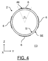
- The is a schematic representation of a cross-sectional view of the reinforced pipeline of the .
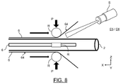
- The is a cross-sectional view of the step of simultaneously attaching the plurality of reinforcing strips to the thermoplastic tube.
- the invention relates to a pipe intended to be mounted in a fluid circuit of an aircraft, for example a drinking water circuit.
- a fluid circuit comprises a plurality of pipes mechanically and fluidly connected to each other and in which a fluid circulates.
- each pipe 1 has a predetermined profile to follow, for example, the curvatures of the structure of the aircraft or to circumvent equipment.
- each pipe 1 can locally be bent.
- the pipe 1 In the initial state, represented on the , the pipe 1 extends longitudinally along an X axis, transversely along a Y axis and vertically along a Z axis, so as to form an orthogonal marker (X, Y, Z).
- Each pipe 1 comprises a tube 2 and two connection ends 3. It goes without saying that the tube 2 comprising two connection ends 3 can be part of an assembly comprising one or more connecting fittings, as is known.
- the connection ends are known per se to those skilled in the art, so they will not be described in more detail in this document.
- the tube 2 has a cylindrical shape and defines an inner surface SI, intended to be in contact with the fluid, and an outer surface SE opposite the inner surface SI ( Figures 3 and 4).
- the section is circular.
- the tube 2 consists of a thermoplastic material, that is to say that it is entirely made of thermoplastic material, allowing the use of a light material.
- the tube 2 has no reinforcing fibers in the thickness of its wall.
- the tube 2 is made of polyaryletherketones (PAEK).
- PAEK polyaryletherketones
- the tube 2 can be made from a different thermoplastic resin, for example polyetherimide (PEI).
- the tube 2 preferably has in the initial state a length L2 of between 500 and 3000 mm.
- the tube 2 also has a thickness Ep2 (shown on the ) preferably between 0.8 and 1.3 mm.
- Pipe 1 is thus light and easy to handle when it is installed in a fluid circuit.
- the tube 2 comprises one or more portion(s) called “portion to be reinforced” 21.
- the tube 2 comprises two portions to be reinforced 21A, 21B, extending longitudinally along an axis of portion U.
- the axis of portion U coincides with the longitudinal axis X.
- the tube 2 also comprises a so-called "portion to bend" portion 22.
- the portion to be bent 22 is positioned between the two portions to be reinforced 21A, 21B, as represented on the .
- Such a portion to be bent 22 corresponds to a portion of the tube 2 which is not to be reinforced and more precisely which must not be reinforced, as will be described in more detail below.
- the tube 2 comprises a plurality of portions not to be reinforced.
- the portions not to be reinforced correspond to the portions to be bent 22 and to end portions 23, intended to be connected to a connection end 3.
- This document presents the example of a tube 2 of pipe 1 comprising two portions to be reinforced 21A, 21B and a portion to be bent 22.
- the tube 2 can comprise a different number of portions to be reinforced 21 and of portions to be bent 22.
- the tube 2 comprises two reinforced portions 4A, 4B (corresponding to the two portions to be reinforced 21A, 21B of the initial state), each extending along a portion axis UA, UB, and a curved portion 5 ( corresponding to the portion to be bent 22 of the initial state), positioned between the two reinforced portions 4A, 4B.
- the portions to be reinforced 21A, 21B make it possible to form the reinforced portions A, 4B in the final state and the portion to be bent 22 makes it possible to form the curved portion 5 in the final state.
- the pipe 1 comprises one or more reinforcing strip(s) 6 extending longitudinally on the outer surface SE of each portion to be reinforced 21A, 21B of the tube 2, so as to ultimately form a reinforced portion 4 , as will be discussed in more detail later.
- portion to be reinforced 21A, 21B denotes the tube portions 2 intended to receive one or more reinforcing strips 6, and the term “reinforced portion” 4 denotes the tube portions 2 on which strips are applied. reinforcement 6.
- pipe 1 comprises at least one reinforcing strip 6 on each reinforced portion 4 of tube 2.
- the reinforced portions 4 of the same tube 2 are associated with the same number of reinforcing strips 6.
- the pipe 1 comprises three reinforcing strips 6 on each reinforced portion 4, the three reinforcing strips 6 being distributed angularly on the outer surface SE of the tube 2 and being positioned equidistant from them. each other.
- the pipe 1 comprises four reinforcing strips 6 on each reinforced portion 4, the four reinforcing strips 6 being distributed angularly on the outer surface SE of the tube 2 and being positioned equidistant from each other.
- the number of reinforcing strips 6 could be different, it is preferably even.
- the reinforcing strips 6 are preferably arranged symmetrically in order to limit buckling in two opposite directions.
- each reinforcing strip 6 extends, in a cross-sectional plane (Y, Z), over an angular range ⁇ comprised between 28 and 58°, represented on the .
- Such an angular range ⁇ is a function of the radius of the tube 2.
- each reinforcing strip 6 preferably extends over an angular perimeter A6 of between 31% and 64% of the outer perimeter of the tube 2.
- each reinforcing strip 6 extends longitudinally along an axis I, transversely along an axis J and vertically along an axis K, so as to form an orthogonal mark (I, J, K).
- the longitudinal axis I of the reinforcement strip 6 coincides with the longitudinal axis X of the pipe 1.
- Each reinforcing strip 6 has a lower surface 63, intended to be in contact with the outer surface SE of the tube 2, and an upper surface 64 opposite the lower surface 63.
- each reinforcing strip 6 comprises reinforcing fibers 61 impregnated in a thermoplastic resin 62.
- the thermoplastic resin 62 of the reinforcing strip 6 is identical to the thermoplastic material of the tube 2, so as to allow efficient and homogeneous connection between each portion to be reinforced 21A, 21B of the tube 2 and the reinforcement strip 6.
- the thermoplastic resin 62 of the reinforcement strip 6 is preferably polyaryletherketone (PAEK). It goes without saying that the reinforcing strip 6 can be made of a different thermoplastic resin, for example polyetherimide (PEI) compatible with polyaryletherketones (PAEK).
- Each reinforcing strip 6 is configured to be fixed to the outer surface SE of the tube 2 preferably by bonding by welding. Such a bonding method is known per se for the assembly of thermoplastic parts. It goes without saying that the reinforcing strips 6 can be mechanically connected to the outer surface SE of the tube 2 by any other means, for example, by applying glue.
- the reinforcing fibers 61 are unidirectional fibers extending longitudinally along the axis I, as shown in the . Such unidirectional fibers are advantageous for reducing buckling along the direction of said fibers.
- the reinforcing fibers 61 are preferably glass fibers, carbon or aramid fibers.
- each reinforcing strip 6 may comprise a stack of several layers of unidirectional reinforcing fibers 61 to allow even greater reinforcement of the tube 2.
- each reinforcing strip 6 has a width L6 along the axis J of between 1/8 inch ie 3.2 mm and 1 ⁇ 2 inch ie 12.7 mm.
- a width L6 is substantially equal to 1 ⁇ 4 inch (6.35 mm), so as to cover 31%, 43% or 64% of the outer surface SE of the tube 2, respectively for a tube with a diameter of 1 inch. (25.4 mm), 3 ⁇ 4 inch (19.05 mm) or 1 ⁇ 2 inch (12.7 mm).
- Each reinforcing strip 6 also has a length M6 along the axis I previously defined according to the length of the portion to be reinforced 21A, 21B on which the reinforcing strip 6 is intended to be applied.
- the length M6 is thus preferably between 450 and 700 mm, so as to apply a reinforcing strip 6 over the entire length of each portion to be reinforced 21A, 21B.
- the reinforcing strip 6 is packaged in a roll and cut to the desired length.
- each reinforcing strip 6 has a thickness Ep6 of between 0.1 and 0.4 mm.
- a thickness Ep6 of the reinforcing strip 6 makes it possible to limit the increase in the total thickness of the tube 2, which makes it possible not to impact the production line of the pipes 1, by allowing the use of known machines and already used in this area.
- the latter can be mounted in the machines of the existing production line and in particular in the machines of existing bending.
- each reinforced portion 4 has a thickness close to the thickness of the unreinforced portions, which makes it possible not to impact the industrial process for manufacturing the pipe 1.
- a process for manufacturing a pipe 1 according to an embodiment of the invention will now be described, with reference to FIGS. 7 to 9.
- the pipe 1 is initially in its initial state. , shown on the and in which the tube 2 extends entirely along the longitudinal axis X.
- the method firstly comprises a step E1 of determining one or more portion(s) to be reinforced 21 of the tube 2.
- the operator also determines, in a second step of determining E2, one or more portion(s) ( s) to bend 22 of the tube 2.
- the operator determines two portions to be reinforced 21A, 21B and a portion to bend 22, the portion to be bent 22 being positioned between the two portions to be reinforced 21A, 21B, as represented on the .
- the operator positions in this example, in a positioning step E3, four reinforcing strips 6 on the outer surface SE of the first portion to be reinforced 21A of the tube 2.
- the reinforcing strips 6 are positioned so as to be distributed angularly on the outer surface SE of the tube 2, being positioned equidistant from each other, as shown in the . It goes without saying that the number of reinforcing strips 6 positioned on the outer surface SE of the tube 2 could be different.
- the operation is then repeated for the positioning in this example of four reinforcing strips 6 on the outer surface SE of the second portion 21B to be reinforced. In this step, no reinforcing strip 6 is positioned on the outer surface SE of the portion 22 to be bent, which then consists only of thermoplastic material.
- the operator places, in a positioning step E4, four pressure members R on the outer surface SE of the tube 2.
- the four pressure members R are preferably distributed angularly on the periphery of the tube 2, equidistant from each other.
- the four pressure members R are positioned at the periphery of the tube 2 so as to be centered on each reinforcing strip 6, allowing effective and optimal application of the reinforcing strips 6
- This document presents the example of four pressure members R, however it goes without saying that the number of pressure members R can be different, as long as the pressure members R are evenly distributed on the periphery of the tube 2, so as to ensure a uniform pressure on the periphery of the tube 2 and thus avoid any deformation of the tube 2, as will be described in more detail later.
- each pressure member R is in the form of a roller which rotates around an axis V (represented on the ) and which moves along the longitudinal axis X of the tube 2, to enable the reinforcement strips 6 to be applied over their entire length M6. It goes without saying that each pressure member R in the form of a roller could just as well be fixed.
- the method then comprises, preferably, a step of simultaneous heating E5, by a heating device S (shown in the ), of the outer surface SE of the first portion to be reinforced 21A of the tube 2 and of the lower surface 63 of each reinforcement strip 6, so as to allow welding by gluing of the reinforcement strip 6 to the first portion to be reinforced 21A to form the first reinforced portion 4A.
- a heating device S shown in the , of the outer surface SE of the first portion to be reinforced 21A of the tube 2 and of the lower surface 63 of each reinforcement strip 6, so as to allow welding by gluing of the reinforcement strip 6 to the first portion to be reinforced 21A to form the first reinforced portion 4A.
- the heating device S can be of the radiative (for example infrared, laser), conductive (heating die), convective (hot air), inductive or mechanical (ultrasound friction) type.
- each pressure member R then simultaneously applies an identical radial pressure force P on the upper surface 64 of each reinforcing strip 6 positioned on the outer surface SE of the first portion to be reinforced 21A of the tube 2 , as shown in Figures 8 and 9.
- Such a step makes it possible to simultaneously deposit all the reinforcing strips 6.
- the distribution of the pressure members R and the application of the same pressure force P allows the uniform application of a pressure on the periphery of the tube 2, so as to overcome any risk of deformation of the tube 2.
- the steps of heating E5 and applying E6 of a force allow the assembly by welding of the reinforcing strips 6 on tube 2.
- the heating device S and the pressure members R move successively and progressively along the longitudinal axis X of the tube 2 , as shown in the , so as to gradually deposit the reinforcing strips 6 over the entire length of the first portion 21A to be reinforced.
- This document presents the example of a fixed tube 2 along which the pressure members R move in the form of rollers, however it goes without saying that each pressure member R, as well as the heating device S, could just as well be fixed.
- the tube 2 would then move longitudinally along its axis X in order to deposit the reinforcing strips 6 over the entire length of the first portion 21A to be reinforced in a manner similar to the steps of heating E5 and applying E6 described previously.
- the reinforcing strips 6 are thus secured to the outer surface SE of the first portion to be reinforced 21A of the tube 2, thus forming the first reinforced portion 4A, represented on the .
- the steps of heating E5 and applying E6 of a pressure force P are then repeated for the second portion 21B to be reinforced, so as to form the second reinforced portion 4B.
- the manufacturing process then comprises a bending step E7 of the portion to be bent 22, so as to form the bent portion 5. Thanks to the prior determination of the portions to be reinforced 21 and the portions to be bent 22 and thanks to the thin thickness and to the material of the reinforcing strips 6, this bending step E7 can easily be carried out by known and commonly used production machines. No fiber is bent, which is advantageous.
- the pipe production chain is not impacted and the pipe is locally reinforced, which allows it to resist buckling.
Landscapes
- Engineering & Computer Science (AREA)
- General Engineering & Computer Science (AREA)
- Mechanical Engineering (AREA)
- Textile Engineering (AREA)
- Chemical & Material Sciences (AREA)
- Composite Materials (AREA)
- Rigid Pipes And Flexible Pipes (AREA)
- Shaping Of Tube Ends By Bending Or Straightening (AREA)
Abstract
Description
- une étape de détermination d’au moins une portion à renforcer du tube, et
- une étape de positionnement d’au moins une bande de renfort sur la surface extérieure de la portion à renforcer du tube.
- une étape de détermination d’au moins deux portions à renforcer,
- une étape de détermination d’au moins une portion à cintrer, la portion à cintrer étant positionnée entre les deux portions à renforcer,
- une étape de positionnement d’au moins une bande de renfort sur la surface extérieure des deux portions à renforcer, la portion à cintrer étant exempte de bande de renfort, puis
- une étape de cintrage de la portion à cintrer.
Claims (8)
- Procédé de fabrication d’une canalisation destinée à être montée dans un circuit de fluide (C) d’un aéronef, la canalisation (1) comprenant un tube (2) et deux extrémités de connexion (3), le tube (2) étant constitué d’un matériau thermoplastique et présentant une forme cylindrique, le tube (2) définissant une surface intérieure (SI), destinée à être en contact avec le fluide, et une surface extérieure (SE) opposée à la surface intérieure (SI), le procédé de fabrication, comprenant :
- une étape de détermination (E1) d’au moins deux portions à renforcer (21) du tube (2),
- une étape de détermination (E2) d’au moins une portion à cintrer (22), la portion à cintrer (22) étant positionnée entre les deux portions à renforcer (21),
- une étape de positionnement (E3) d’au moins une bande de renfort (6) s’étendant longitudinalement sur la surface extérieure (SE) des deux portions à renforcer (21), la portion à cintrer (22) étant exempte de bande de renfort (6), puis
- une étape de cintrage (E7) de la portion à cintrer (22).
- Procédé de fabrication selon la revendication 1, dans laquelle la bande de renfort (6) comprend des fibres de renfort (61) imprégnées dans une résine thermoplastique (62).
- Procédé de fabrication selon la revendication 2, dans laquelle la résine thermoplastique (62) de la bande de renfort (6) est identique au matériau thermoplastique du tube (2).
- Procédé de fabrication selon la revendication 3, dans laquelle la résine thermoplastique (62) de la bande de renfort (6) et du tube (2) est du polyaryléthercétones (PAEK).
- Procédé de fabrication selon l’une des revendications 2 à 4, dans laquelle les fibres de renfort (61) sont des fibres unidirectionnelles.
- Procédé de fabrication selon l’une des revendications 1 à 5, dans laquelle, dans un plan en coupe transversale, la ou les bandes de renfort (6) s’étendent sur une plage angulaire (α) comprise entre 28 et 58 ° à la périphérie de la portion renforcée (4).
- Procédé de fabrication selon l’une des revendications 1 à 6, dans laquelle la portion renforcée (4) comprend au moins trois bandes de renfort (6) réparties angulairement sur la surface extérieure (SE) de la portion renforcée (4) et positionnées à équidistance les unes des autres.
- Procédé de fabrication selon l’une des revendications 1 à 7, dans laquelle la bande de renfort (6) présente une épaisseur (Ep6) comprise entre 0,1 et 0,4 mm.
Priority Applications (3)
| Application Number | Priority Date | Filing Date | Title |
|---|---|---|---|
| CA3198299A CA3198299A1 (fr) | 2020-11-19 | 2021-11-08 | Procede de fabrication d'une canalisation thermoplastique renforcee comportant une portion cintree |
| US18/253,369 US12370737B2 (en) | 2020-11-19 | 2021-11-08 | Reinforced thermoplastic pipe |
| EP21806718.9A EP4204205B1 (fr) | 2020-11-19 | 2021-11-08 | Procede de fabrication d'une canalisation thermoplastique renforcee comportant une portion cintree |
Applications Claiming Priority (2)
| Application Number | Priority Date | Filing Date | Title |
|---|---|---|---|
| FR2011878A FR3116320B1 (fr) | 2020-11-19 | 2020-11-19 | Canalisation thermoplastique renforcée |
| FRFR2011878 | 2020-11-19 |
Publications (1)
| Publication Number | Publication Date |
|---|---|
| WO2022106231A1 true WO2022106231A1 (fr) | 2022-05-27 |
Family
ID=74125506
Family Applications (1)
| Application Number | Title | Priority Date | Filing Date |
|---|---|---|---|
| PCT/EP2021/080892 Ceased WO2022106231A1 (fr) | 2020-11-19 | 2021-11-08 | Procede de fabrication d'une canalisation thermoplastique renforcee comportant une portion cintree |
Country Status (5)
| Country | Link |
|---|---|
| US (1) | US12370737B2 (fr) |
| EP (1) | EP4204205B1 (fr) |
| CA (1) | CA3198299A1 (fr) |
| FR (1) | FR3116320B1 (fr) |
| WO (1) | WO2022106231A1 (fr) |
Citations (5)
| Publication number | Priority date | Publication date | Assignee | Title |
|---|---|---|---|---|
| US20140238525A1 (en) * | 2013-02-22 | 2014-08-28 | Thercom Holdings, Llc | Thermoplastic composite pipe with longitudinal reinforcement |
| EP3285985A1 (fr) * | 2015-04-23 | 2018-02-28 | CMP Automation Inc. | Procédé et appareil de cintrage de tubes en matière plastique |
| US20190113158A1 (en) * | 2017-10-13 | 2019-04-18 | Eaton Intelligent Power Limited | Lightweight composites tubes for high pressure aerospace hydraulic application |
| EP3548196A1 (fr) * | 2017-12-13 | 2019-10-09 | Stelia Aerospace | Canalisation tubulaire longitudinale comportant un organe intercalaire et procedes de montage et de cintrage d'une telle canalisation |
| FR3081532A1 (fr) * | 2018-05-25 | 2019-11-29 | Stelia Aerospace | Canalisation comportant une extremite ouverte comportant une surface de butee oblique |
Family Cites Families (3)
| Publication number | Priority date | Publication date | Assignee | Title |
|---|---|---|---|---|
| GB0612991D0 (en) * | 2006-06-29 | 2006-08-09 | Bhp Billiton Petroleum Pty Ltd | Improvements relating to hose |
| DE102009023289B4 (de) * | 2009-05-29 | 2013-02-28 | Helmut Schlösser | Kunststoffrohr |
| US11009256B2 (en) * | 2018-12-20 | 2021-05-18 | The Boeing Company | Crack-resistant polymer foam ducts and method of installing same |
-
2020
- 2020-11-19 FR FR2011878A patent/FR3116320B1/fr active Active
-
2021
- 2021-11-08 WO PCT/EP2021/080892 patent/WO2022106231A1/fr not_active Ceased
- 2021-11-08 US US18/253,369 patent/US12370737B2/en active Active
- 2021-11-08 CA CA3198299A patent/CA3198299A1/fr active Pending
- 2021-11-08 EP EP21806718.9A patent/EP4204205B1/fr active Active
Patent Citations (5)
| Publication number | Priority date | Publication date | Assignee | Title |
|---|---|---|---|---|
| US20140238525A1 (en) * | 2013-02-22 | 2014-08-28 | Thercom Holdings, Llc | Thermoplastic composite pipe with longitudinal reinforcement |
| EP3285985A1 (fr) * | 2015-04-23 | 2018-02-28 | CMP Automation Inc. | Procédé et appareil de cintrage de tubes en matière plastique |
| US20190113158A1 (en) * | 2017-10-13 | 2019-04-18 | Eaton Intelligent Power Limited | Lightweight composites tubes for high pressure aerospace hydraulic application |
| EP3548196A1 (fr) * | 2017-12-13 | 2019-10-09 | Stelia Aerospace | Canalisation tubulaire longitudinale comportant un organe intercalaire et procedes de montage et de cintrage d'une telle canalisation |
| FR3081532A1 (fr) * | 2018-05-25 | 2019-11-29 | Stelia Aerospace | Canalisation comportant une extremite ouverte comportant une surface de butee oblique |
Also Published As
| Publication number | Publication date |
|---|---|
| EP4204205A1 (fr) | 2023-07-05 |
| US20240025105A1 (en) | 2024-01-25 |
| FR3116320B1 (fr) | 2023-11-24 |
| EP4204205B1 (fr) | 2024-04-17 |
| US12370737B2 (en) | 2025-07-29 |
| FR3116320A1 (fr) | 2022-05-20 |
| CA3198299A1 (fr) | 2022-05-27 |
Similar Documents
| Publication | Publication Date | Title |
|---|---|---|
| EP3014157B1 (fr) | Conduite flexible et procédé associé | |
| EP1121553B1 (fr) | Assemblage filete integral de deux tubes metalliques | |
| FR3017439A1 (fr) | Conduite flexible de transport de fluide munie d'un insert en forme de s etendu et procede de fabrication associe | |
| FR2737173A1 (fr) | Colonne de direction reglable en profondeur, avec dispositif de guidage | |
| FR2725259A1 (fr) | Bague d'etancheite activee par pression | |
| WO2008043891A2 (fr) | Element de conduite haute pression comportant un assemblage de tubes frettes et methode de fabrication | |
| FR2760506A1 (fr) | Bague d'etancheite activee par pression | |
| FR2899665A1 (fr) | "conduite flexible a embouts d'extremite integres" | |
| EP2964991B1 (fr) | Méthode de montage d'un embout de conduite flexible et pré-assemblage associé | |
| EP3692295B1 (fr) | Embout de fixation d'une conduite flexible, conduite flexible et procédé associés | |
| EP4204205B1 (fr) | Procede de fabrication d'une canalisation thermoplastique renforcee comportant une portion cintree | |
| FR2970759A1 (fr) | Systeme de fixation de canalisations de transfert de fluide | |
| CA2075906A1 (fr) | Raidisseur a structure renforcee | |
| EP3638484B1 (fr) | Conduit pour réservoir à carburant de véhicule convenant pour la soudure et procédé | |
| EP4196713B1 (fr) | Conduite de fluide pour aéronef comprenant une canalisation thermoplastique et un connecteur | |
| WO2002008656A1 (fr) | Embout de connexion rapide | |
| FR2656403A1 (fr) | Procede de fixation d'une piece de raccordement a l'extremite d'une canalisation et raccord de canalisation obtenu par ce procede. | |
| FR3160224A1 (fr) | Canalisation pour circuit de fluide d’aéronef comprenant un connecteur comportant une portion d’insertion pour un tube et procédé d’assemblage | |
| WO2009066027A1 (fr) | Procede de montage d'un embout sur une conduite pour former un raccord | |
| FR3160002A1 (fr) | Raccord mécanique | |
| WO2025082910A1 (fr) | Plaquette de frein et procede d'assemblage | |
| FR2980999A1 (fr) | Procede de fabrication d'un raccord en matiere plastique et raccord ainsi obtenu | |
| WO2019229336A1 (fr) | Ensemble de direction comprenant un élément d'étanchéité améliorant une étanchéité d'une rotule de direction | |
| FR3015628A1 (fr) | Embout de connexion d'une conduite flexible, conduite flexible et procede associes | |
| FR2764277A1 (fr) | Cylindre rotatif a faible inertie de masse |
Legal Events
| Date | Code | Title | Description |
|---|---|---|---|
| 121 | Ep: the epo has been informed by wipo that ep was designated in this application |
Ref document number: 21806718 Country of ref document: EP Kind code of ref document: A1 |
|
| ENP | Entry into the national phase |
Ref document number: 2021806718 Country of ref document: EP Effective date: 20230326 |
|
| ENP | Entry into the national phase |
Ref document number: 3198299 Country of ref document: CA |
|
| WWE | Wipo information: entry into national phase |
Ref document number: 18253369 Country of ref document: US |
|
| NENP | Non-entry into the national phase |
Ref country code: DE |
|
| WWG | Wipo information: grant in national office |
Ref document number: 18253369 Country of ref document: US |