WO2022112689A1 - Bande de roulement de pneumatique pour un véhicule poids lourd ayant une résistance aux agressions améliorée - Google Patents
Bande de roulement de pneumatique pour un véhicule poids lourd ayant une résistance aux agressions améliorée Download PDFInfo
- Publication number
- WO2022112689A1 WO2022112689A1 PCT/FR2021/052039 FR2021052039W WO2022112689A1 WO 2022112689 A1 WO2022112689 A1 WO 2022112689A1 FR 2021052039 W FR2021052039 W FR 2021052039W WO 2022112689 A1 WO2022112689 A1 WO 2022112689A1
- Authority
- WO
- WIPO (PCT)
- Prior art keywords
- tread
- height
- equal
- cavity
- external
- Prior art date
- Legal status (The legal status is an assumption and is not a legal conclusion. Google has not performed a legal analysis and makes no representation as to the accuracy of the status listed.)
- Ceased
Links
Classifications
-
- B—PERFORMING OPERATIONS; TRANSPORTING
- B60—VEHICLES IN GENERAL
- B60C—VEHICLE TYRES; TYRE INFLATION; TYRE CHANGING; CONNECTING VALVES TO INFLATABLE ELASTIC BODIES IN GENERAL; DEVICES OR ARRANGEMENTS RELATED TO TYRES
- B60C11/00—Tyre tread bands; Tread patterns; Anti-skid inserts
- B60C11/03—Tread patterns
- B60C11/0306—Patterns comprising block rows or discontinuous ribs
- B60C11/0309—Patterns comprising block rows or discontinuous ribs further characterised by the groove cross-section
-
- B—PERFORMING OPERATIONS; TRANSPORTING
- B60—VEHICLES IN GENERAL
- B60C—VEHICLE TYRES; TYRE INFLATION; TYRE CHANGING; CONNECTING VALVES TO INFLATABLE ELASTIC BODIES IN GENERAL; DEVICES OR ARRANGEMENTS RELATED TO TYRES
- B60C11/00—Tyre tread bands; Tread patterns; Anti-skid inserts
- B60C11/03—Tread patterns
- B60C11/032—Patterns comprising isolated recesses
- B60C11/0323—Patterns comprising isolated recesses tread comprising channels under the tread surface, e.g. for draining water
-
- B—PERFORMING OPERATIONS; TRANSPORTING
- B60—VEHICLES IN GENERAL
- B60C—VEHICLE TYRES; TYRE INFLATION; TYRE CHANGING; CONNECTING VALVES TO INFLATABLE ELASTIC BODIES IN GENERAL; DEVICES OR ARRANGEMENTS RELATED TO TYRES
- B60C11/00—Tyre tread bands; Tread patterns; Anti-skid inserts
- B60C11/03—Tread patterns
- B60C11/12—Tread patterns characterised by the use of narrow slits or incisions, e.g. sipes
- B60C11/1236—Tread patterns characterised by the use of narrow slits or incisions, e.g. sipes with special arrangements in the tread pattern
- B60C11/125—Tread patterns characterised by the use of narrow slits or incisions, e.g. sipes with special arrangements in the tread pattern arranged at the groove bottom
-
- B—PERFORMING OPERATIONS; TRANSPORTING
- B60—VEHICLES IN GENERAL
- B60C—VEHICLE TYRES; TYRE INFLATION; TYRE CHANGING; CONNECTING VALVES TO INFLATABLE ELASTIC BODIES IN GENERAL; DEVICES OR ARRANGEMENTS RELATED TO TYRES
- B60C11/00—Tyre tread bands; Tread patterns; Anti-skid inserts
- B60C11/03—Tread patterns
- B60C11/12—Tread patterns characterised by the use of narrow slits or incisions, e.g. sipes
- B60C11/1272—Width of the sipe
- B60C11/1281—Width of the sipe different within the same sipe, i.e. enlarged width portion at sipe bottom or along its length
-
- B—PERFORMING OPERATIONS; TRANSPORTING
- B60—VEHICLES IN GENERAL
- B60C—VEHICLE TYRES; TYRE INFLATION; TYRE CHANGING; CONNECTING VALVES TO INFLATABLE ELASTIC BODIES IN GENERAL; DEVICES OR ARRANGEMENTS RELATED TO TYRES
- B60C11/00—Tyre tread bands; Tread patterns; Anti-skid inserts
- B60C11/03—Tread patterns
- B60C11/032—Patterns comprising isolated recesses
-
- B—PERFORMING OPERATIONS; TRANSPORTING
- B60—VEHICLES IN GENERAL
- B60C—VEHICLE TYRES; TYRE INFLATION; TYRE CHANGING; CONNECTING VALVES TO INFLATABLE ELASTIC BODIES IN GENERAL; DEVICES OR ARRANGEMENTS RELATED TO TYRES
- B60C11/00—Tyre tread bands; Tread patterns; Anti-skid inserts
- B60C11/03—Tread patterns
- B60C2011/0337—Tread patterns characterised by particular design features of the pattern
- B60C2011/0339—Grooves
- B60C2011/0341—Circumferential grooves
- B60C2011/0346—Circumferential grooves with zigzag shape
-
- B—PERFORMING OPERATIONS; TRANSPORTING
- B60—VEHICLES IN GENERAL
- B60C—VEHICLE TYRES; TYRE INFLATION; TYRE CHANGING; CONNECTING VALVES TO INFLATABLE ELASTIC BODIES IN GENERAL; DEVICES OR ARRANGEMENTS RELATED TO TYRES
- B60C11/00—Tyre tread bands; Tread patterns; Anti-skid inserts
- B60C11/03—Tread patterns
- B60C2011/0337—Tread patterns characterised by particular design features of the pattern
- B60C2011/0339—Grooves
- B60C2011/0341—Circumferential grooves
- B60C2011/0355—Circumferential grooves characterised by depth
-
- B—PERFORMING OPERATIONS; TRANSPORTING
- B60—VEHICLES IN GENERAL
- B60C—VEHICLE TYRES; TYRE INFLATION; TYRE CHANGING; CONNECTING VALVES TO INFLATABLE ELASTIC BODIES IN GENERAL; DEVICES OR ARRANGEMENTS RELATED TO TYRES
- B60C2200/00—Tyres specially adapted for particular applications
- B60C2200/06—Tyres specially adapted for particular applications for heavy duty vehicles
Definitions
- Tire tread for a heavy-duty vehicle having improved resistance to attacks
- the subject of the present invention is a tire tread for a heavy vehicle, more particularly for a mixed-use heavy vehicle, which can be driven both on the road, on tarmacked surfaces, and off the road, on stony ground.
- a tread consisting of at least one rubber-based material, is the wearing part of the tire, located at its periphery and intended to be worn when it comes into contact with the ground by means of a running surface. It most often includes a tread pattern which is a combination of cutouts, or hollows, and elements in relief, of the block type or of the rib type, intended essentially to ensure satisfactory performance in grip, more particularly on wet road surfaces.
- the cutouts allowing the evacuation of water are essentially wide cutouts called grooves.
- a groove has a width such that the walls of material facing it delimiting it do not come into contact with each other, during the passage of the tread in the contact surface, when the tire is subject to recommended inflation and load conditions as defined in particular by the European standards of the "European Tire and Rim Technical Organization” or "ETRT0" in its “Standards Manual 2020 - Commercial Vehicle Tyres”. commercial).
- the compression and shear deformations of the elements in relief delimiting the groove condition the pressures in contact with the ground and therefore the wear.
- these deformations by generating hysteretic losses in the material of the tread, impact the rolling resistance, and therefore the fuel consumption of the vehicle.
- a tread may also comprise narrow cutouts or incisions.
- An incision has a width such that the walls of material facing it delimiting it come into contact at least partially with each other, during the passage of the tread in the contact surface, under the conditions load and tire pressure specified by the E.T.R.T.O and seen previously.
- An incision does not make it possible to evacuate the water, but, vis-à-vis the grip, has an edge effect in the contact with the ground, which makes it possible in particular to break a film of water possibly present on floor.
- Treads comprising such complex cutouts have been described in particular in the documents WO 2011039194, WO 2011101495, WO 2012130735, WO 2016188956, WO 2019008276 and WO 2019122677. regular or not, on the running surface when new.
- Each complex cutout has external cavities, open to the tread surface and disjoint from each other in the main direction of the complex cutout.
- the main direction of the complex cutout generally corresponds to the direction of flow of the water in said cutout when driving on ground covered with water.
- This complex cutout includes, in addition to the external cavities, internal cavities formed inside the tread and generally connected to the running surface through incisions.
- These internal cavities are positioned radially and completely inside the running surface when new, and interposed between the external cavities.
- the internal cavities can be positioned at different levels of depth in the thickness of the strip.
- the continuity of the water flow in each complex cutout, when new, is ensured by connecting portions, generally connecting channels, between two consecutive outer and inner cavities respectively.
- the assembly formed by the external cavities, the internal cavities and the connecting channels thus forms a continuous groove.
- the juxtaposition of internal and external cavities not linked together, and therefore not allowing a flow of fluid from one to the other over the entire circumference of the tire does not constitute a continuous groove.
- the volume of all the internal cavities, the external cavities and the connecting channels is reduced compared to that of grooves that are entirely open on the tread surface when new and having a depth corresponding to the maximum depth of the internal or external cavities.
- the presence of complex cutouts thus makes it possible to limit the reduction in rigidity of the tread when new due to the presence of the grooves.
- a tread pattern can comprise both complex cutouts, emerging on the running surface intermittently, and conventional grooves, emerging on the running surface over their entire length.
- This stone retention phenomenon can be particularly marked in the case of complex cutouts. Indeed these can capture stones at the level of their external cavities, these stones being likely to remain blocked, more particularly, in the connection channels between the respectively external and internal cavities, and therefore to generate damage to the tread.
- the tread in new condition comprising at least one complex cutout comprising, along an average line, an alternation of external cavities, opening onto the rolling surface, and internal cavities, not opening onto the rolling surface, two consecutive external and internal cavities respectively being interconnected by a connecting channel,
- each external cavity having, in an average surface containing the average line and a radial direction perpendicular to the rolling surface, a height, measured, in the radial direction, between the rolling surface and an external cavity bottom, and a length , measured, along the mean line, at the level of the tread surface
- -each internal cavity having, in the mean surface, a height, measured, along the radial direction, between a top of the internal cavity and a bottom of the internal cavity radially interior to the bottom of the external cavity, and a length, measured, along the mean line, at the level of the bottom of the internal cavity
- each connecting channel having, in the middle surface, a height, measured, in the radial direction, between a connecting channel top and a connecting channel bottom, at the circumferential junction between the external cavity and the connecting channel , and a length, measured, along the mean line, between the external cavity and the internal cavity, non-zero, -each complex cut-out having, in the mean surface, a height measured, along the radial direction, between the rolling surface and the bottom of the internal cavity,
- each external cavity being at least equal to half the height of the complex cutout
- the height of each connecting channel being at most equal to one third of the height of the complex cutout
- the subject of the invention is therefore a tread comprising at least one complex cutout formed, along a mean line, by an alternation of external cavities, opening onto the tread surface, and internal cavities, not opening onto the rolling surface, two consecutive outer and inner cavities respectively being interconnected by a connecting channel providing a gradual transition between said outer and inner cavities respectively.
- the middle line of the complex cutout is not necessarily rectilinear, and may have, by way of example, a wavy shape or a zigzag shape. In addition, it can extend in any direction: longitudinal, transverse or oblique.
- the longitudinal direction is the direction of the longest tread dimension or length
- the transverse direction is the direction of the intermediate dimension or tread width
- the radial direction is the direction of the longest. small tread dimension or thickness.
- An oblique direction has an intermediate general orientation between the longitudinal direction and the transverse direction.
- An oblique direction is said to be substantially longitudinal, when it forms an angle at most equal to 45° with the longitudinal direction, and substantially transverse, when it forms an angle at most equal to 45° with the transverse direction.
- the complex cutout forms, in a section along an average surface defined by its average line and a radial direction perpendicular to the running surface, a continuous wavy groove comprising an alternation of external cavities, internal cavities and connecting channels between two consecutive internal and external cavities respectively.
- two consecutive external cavities along the mean line are separated by a single internal cavity and vice versa. Due to the undulation of the complex cutout in the circumferential direction, in the thickness of the tread, the bottom of any internal cavity is radially inside the bottom of an adjacent external cavity.
- the respectively external and internal cavities, as well as the connecting channels, are characterized by their respective geometries defined in the average surface of the complex cutout, namely a height measured along the radial direction, in the thickness of the tread, and a length, measured along the mean line of the complex cutout, between two references depending on the complex cutout portion considered.
- the respective heights can be defined with respect to the height of the complex cutout, measured between the running surface in new condition, on which the external cavities open, and a bottom surface passing through the bottom of the internal cavities, c' that is, the radially innermost points of the complex cutout.
- each external cavity is at least equal to half the height of the complex cutout, which guarantees a sufficient volume of external cavity, necessary for the storage of water on wet ground, when the tread is in new condition.
- the length of any connecting channel is non-zero, which guarantees a gradual transition between the respectively external and internal cavities connected by said connecting channel.
- the essential characteristic of the invention is to limit the height of the connecting channel, measured at the level of the connection of the channel with the external cavity, in other words at the level of its section opening into the external cavity. According to the invention, this height is optimized to prevent the passage of too large stones, that is to say of a size such that they would be likely to cause significant damage to the crown of the tire.
- the inventors have estimated a critical stone size characterized by a diameter greater than one third of the height of the complex cutout, hence a height of the connecting channel at the level of its connection with the external cavity at most equal to one third of the height complex cutting.
- each connecting channel is at least equal to one tenth of the height of the complex cutout. Below this value, the flow of water in the complex cutout becomes insufficient to guarantee sufficient grip of the tread on a wet road surface, due to too great a constriction of the complex cutout at the level of the connecting channel. .
- each external cavity is at most equal to three quarters of the height of the complex cutout.
- This maximum external cavity height guarantees the presence, radially inside the external cavity, of a thickness of rubber-based material sufficient to ensure the protection of the portion crown insert radially positioned inside the tread, directly above the external cavity.
- each connecting channel is at least equal to the height of the connecting channel.
- the connecting channel is effective for blocking stones captured by the external cavity to which it is connected, if it is of sufficient length, i.e. if it provides striction over a sufficient distance.
- each internal cavity is at least equal to one third of the height of the complex cutout.
- This minimum internal cavity height guarantees a sufficient external cavity volume, necessary for the storage of water on wet ground, when the tread reaches a level of wear corresponding to the top of the internal cavity, in other words when the cavity internal in turn opens on the running surface in the worn state.
- each internal cavity is at most equal to three quarters of the height of the complex cutout.
- This maximum internal cavity height guarantees the presence, radially outside the internal cavity, of a thickness of rubber-based material sufficient to ensure, when new, the protection of the crown reinforcement portion. radially positioned inside the tread, directly above the internal cavity.
- the ratio between the internal cavity length and the external cavity length is advantageously at least equal to 0.8. Below this value, the external cavity length becomes excessive and penalizes the volume of material to be worn.
- the ratio between the internal cavity length and the external cavity length is again advantageously at most equal to 1.5, preferably at most equal to 1.2. Above this value, the length of the external cavity becomes insufficient to guarantee good collection of the water present on the ground.
- each internal cavity has an internal cavity top extended radially outwards by an incision as far as the rolling surface, due to a technological constraint for manufacturing the cavities. external by molding from the outside of the tread.
- each external cavity has an external cavity bottom extended radially inwards by at least one incision up to, at most, a bottom surface passing through the internal cavity bottom. .
- the tread wear level reaches the bottom of the external cavity, at least one incision appears which will contribute to grip, particularly on wet ground, by creating a ridge effect making it possible to break the film of water present on the ground.
- the middle line of at least one complex cutout is substantially longitudinal, forming at all points an angle at most equal to 45°, preferably at most equal to 20° , with respect to a longitudinal direction of the tread.
- this mean line is preferably oriented in a longitudinal direction, which is the direction of advancement of the tire and the main direction of flow of the water evacuated in the contact surface with the ground.
- At least one complex cutout having a substantially longitudinal mean line is axially positioned in a median portion of the tread having an axial width at most equal to two-thirds of the axial width of the tread, said middle portion being centered on a median plane passing through the middle of the tread surface and perpendicular to the tread surface.
- the axial width of the tread is the axial distance between the axial ends of the running surface, when the tire is inflated and crushed under the pressure and load conditions recommended by the ETRTO standards.
- - Figure 2 Cross-sectional view, along an average complex cut-out surface, of a complex cut-out portion comprising an external cavity, an internal cavity and a connecting channel connecting them.
- Figure 1 is a top view of a tread 1 according to the invention in new condition.
- the tread 1 of the tire intended to come into contact with the ground via a running surface 2, comprises cutouts 3, delimiting elements in relief 4.
- two grooves can be distinguished substantially longitudinal each delimiting a lateral rib and a middle portion 11, said middle portion 11 having, in a transverse direction YY' of the tread, an axial width Wm at most equal to two thirds of the axial width W of the tread .
- the middle portion 11 further comprises two complex cutouts 5 substantially longitudinal, each separating two longitudinal rows of relief elements 4 of block type two by two separated by incisions.
- Each complex cutout 5 comprises, along an average line Lm, an alternation of external cavities 6, opening onto the running surface 2, and internal cavities 7, not opening onto the running surface 2, two cavities respectively external 6 and internal 7 consecutive being interconnected by a connecting channel 8.
- the internal cavities 7 and the connecting channels 8, not visible in the new state of the tread, are shown in dotted lines.
- the average line Lm of each complex cutout 5 has a substantially longitudinal zigzag shape, with a tangent at any point forming, with a longitudinal direction XX' of the tread, an angle at most equal to 45 °, preferably at most equal to 20°.
- Figure 2 is a sectional view, along an average surface Sm of complex cutout, of a portion of complex cutout 5 comprising an external cavity 6 connected at each of its ends to an internal cavity 7 by a connecting channel 8. Only half a internal cavity 7 is represented at each end of the external cavity 6.
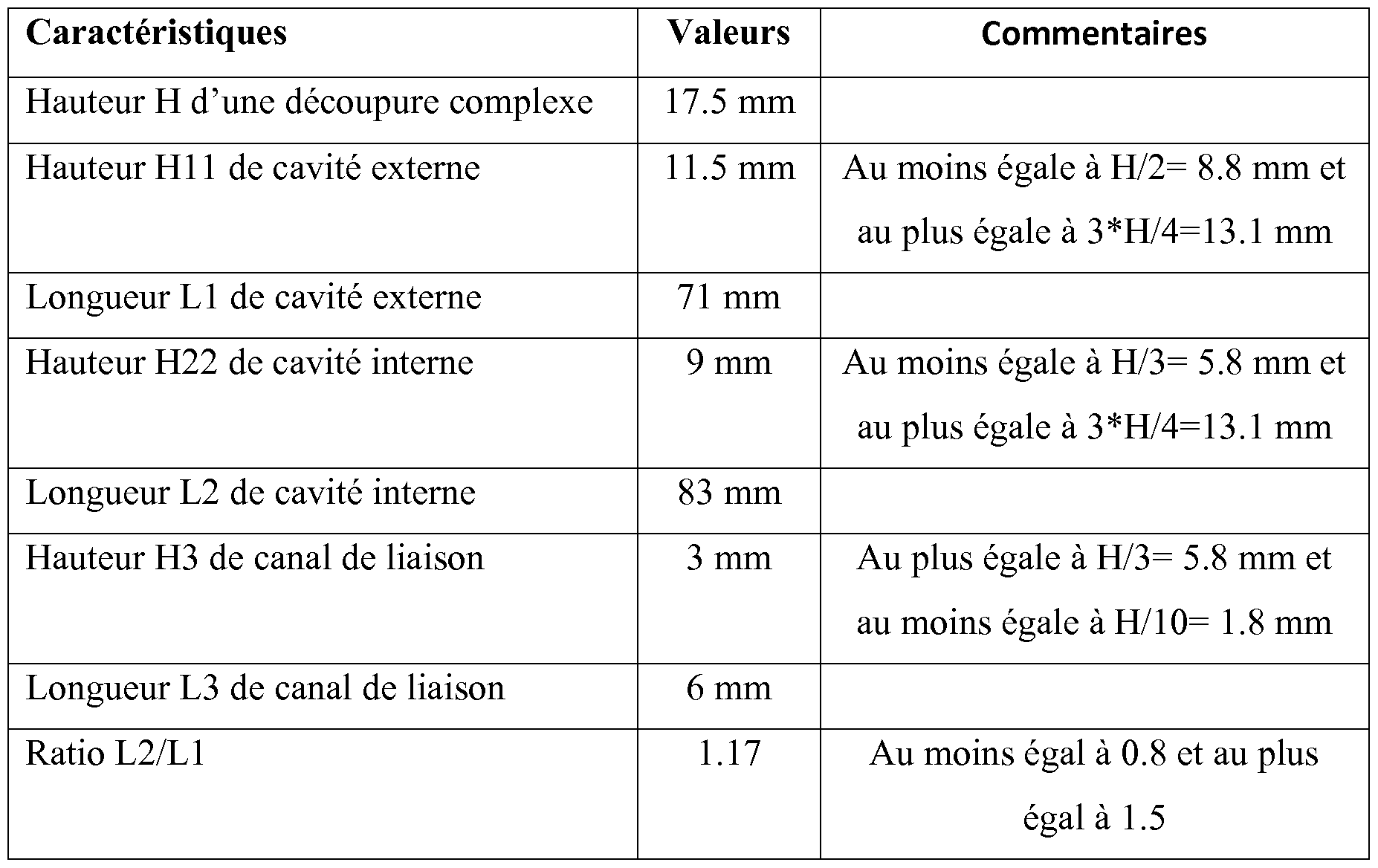
- the external cavity 6 has, in an average surface Sm containing the average line Lm and a radial direction ZZ' perpendicular to the running surface 2 of the tread 1, a height H11, measured, along the radial direction ZZ', between running surface 2 and an external cavity bottom 62, and a length L1, measured, along mean line Lm, at running surface 2.
- Each cavity internal 7 has, in the average surface Sm, a height H22, measured, in the radial direction ZZ', between an internal cavity top 71 and an internal cavity bottom 72 radially inside the external cavity bottom 62, and a length L2 , measured along the mean line Lm, at the level of the bottom of the internal cavity 72.
- FIG. 2 are shown two internal half-cavities 7 of length L2/2.
- Each connecting channel 8 has, in the mean surface Sm, a height H3, measured, along the radial direction ZZ', between a connecting channel top 81 and a connecting channel bottom 82, at the circumferential junction between the cavity external 6 and the connecting channel 8, and a length L3, measured along the mean line Lm, between the external cavity 6 and the internal cavity 7, non-zero.
- the complex cutout 5 has, in the average surface Sm, a height H, measured, along the radial direction ZZ', between the rolling surface 2 and the bottom of the internal cavity 72.
- the height H11 of each external cavity 6 is at least equal to half the height H of the complex cutout 5.
- each connecting channel 8 is at most equal to a third of the height H of the complex cutout 5.
- the external cavity 6 has an external cavity bottom 62 extended radially inwards by an incision 63 up to a bottom surface 10 passing through the internal cavity bottom 72.
- each internal cavity 7 has a top of internal cavity 71 extended radially outwards by an incision 73 up to running surface 2.
- the inventors have more particularly studied this invention for a tire of size 13 R 22.5 intended to equip a steering axle for a mixed-use heavy vehicle and to carry a load equal to 4000 kg with an inflation pressure equal to 8.75 bars, according to the "Standards Manual 2020" of the E.T.R.T.O.
Landscapes
- Engineering & Computer Science (AREA)
- Mechanical Engineering (AREA)
- Tires In General (AREA)
Abstract
Description
Claims
Priority Applications (3)
| Application Number | Priority Date | Filing Date | Title |
|---|---|---|---|
| EP21823964.8A EP4251433A1 (fr) | 2020-11-27 | 2021-11-19 | Bande de roulement de pneumatique pour un véhicule poids lourd ayant une résistance aux agressions améliorée |
| US18/038,918 US12350971B2 (en) | 2020-11-27 | 2021-11-19 | Tire tread for a heavy-duty vehicle having improved resistance to attack |
| CN202180079462.5A CN116568530A (zh) | 2020-11-27 | 2021-11-19 | 用于重型车辆的具有改进的抗攻击性的轮胎胎面 |
Applications Claiming Priority (2)
| Application Number | Priority Date | Filing Date | Title |
|---|---|---|---|
| FRFR2012247 | 2020-11-27 | ||
| FR2012247A FR3116763B1 (fr) | 2020-11-27 | 2020-11-27 | Bande de roulement de pneumatique pour un véhicule poids lourd ayant une résistance aux agressions améliorée |
Publications (1)
| Publication Number | Publication Date |
|---|---|
| WO2022112689A1 true WO2022112689A1 (fr) | 2022-06-02 |
Family
ID=74183431
Family Applications (1)
| Application Number | Title | Priority Date | Filing Date |
|---|---|---|---|
| PCT/FR2021/052039 Ceased WO2022112689A1 (fr) | 2020-11-27 | 2021-11-19 | Bande de roulement de pneumatique pour un véhicule poids lourd ayant une résistance aux agressions améliorée |
Country Status (5)
| Country | Link |
|---|---|
| US (1) | US12350971B2 (fr) |
| EP (1) | EP4251433A1 (fr) |
| CN (1) | CN116568530A (fr) |
| FR (1) | FR3116763B1 (fr) |
| WO (1) | WO2022112689A1 (fr) |
Cited By (1)
| Publication number | Priority date | Publication date | Assignee | Title |
|---|---|---|---|---|
| EP4703155A1 (fr) * | 2024-08-30 | 2026-03-04 | Sumitomo Rubber Industries, Ltd. | Pneumatique |
Citations (9)
| Publication number | Priority date | Publication date | Assignee | Title |
|---|---|---|---|---|
| FR1568434A (fr) * | 1967-04-21 | 1969-05-23 | ||
| EP0206227A2 (fr) * | 1985-06-26 | 1986-12-30 | PIRELLI COORDINAMENTO PNEUMATICI Società per Azioni | Pneumatiques à faible résistance au roulement |
| WO2011039194A1 (fr) | 2009-09-29 | 2011-04-07 | Societe De Technologie Michelin | Bande de roulement pour pneu de rigidite amelioree |
| WO2011101495A1 (fr) | 2010-02-22 | 2011-08-25 | Societe De Technologie Michelin | Dispositif de protection d'une rainure d'une bande de roulement |
| WO2012130735A1 (fr) | 2011-04-01 | 2012-10-04 | Compagnie Generale Des Etablissements Michelin | Bande de roulement comprenant au moins une rainure ondulante et procédé d'obtention |
| WO2016188956A1 (fr) | 2015-05-22 | 2016-12-01 | Compagnie Generale Des Etablissements Michelin | Pneu pour poids lourd avec dispositif indicateur d'usure |
| WO2017176280A1 (fr) * | 2016-04-08 | 2017-10-12 | Compagnie Generale Des Etablissements Michelin | Bande de roulement de pneu de camion et pneu de camion |
| WO2019008276A1 (fr) | 2017-07-05 | 2019-01-10 | Compagnie Generale Des Etablissements Michelin | Pneu dont la bande de roulement comprend des rainures ondulantes |
| WO2019122677A1 (fr) | 2017-12-19 | 2019-06-27 | Compagnie Generale Des Etablissements Michelin | Bande de roulement de pneu comprenant des rainures ondulantes |
Family Cites Families (2)
| Publication number | Priority date | Publication date | Assignee | Title |
|---|---|---|---|---|
| FR3036652B1 (fr) * | 2015-05-28 | 2017-05-19 | Michelin & Cie | Bande de roulement amelioree pour pneu |
| FR3049897A1 (fr) * | 2016-04-08 | 2017-10-13 | Michelin & Cie | Bande de roulement amelioree pour pneu |
-
2020
- 2020-11-27 FR FR2012247A patent/FR3116763B1/fr active Active
-
2021
- 2021-11-19 CN CN202180079462.5A patent/CN116568530A/zh active Pending
- 2021-11-19 US US18/038,918 patent/US12350971B2/en active Active
- 2021-11-19 EP EP21823964.8A patent/EP4251433A1/fr active Pending
- 2021-11-19 WO PCT/FR2021/052039 patent/WO2022112689A1/fr not_active Ceased
Patent Citations (9)
| Publication number | Priority date | Publication date | Assignee | Title |
|---|---|---|---|---|
| FR1568434A (fr) * | 1967-04-21 | 1969-05-23 | ||
| EP0206227A2 (fr) * | 1985-06-26 | 1986-12-30 | PIRELLI COORDINAMENTO PNEUMATICI Società per Azioni | Pneumatiques à faible résistance au roulement |
| WO2011039194A1 (fr) | 2009-09-29 | 2011-04-07 | Societe De Technologie Michelin | Bande de roulement pour pneu de rigidite amelioree |
| WO2011101495A1 (fr) | 2010-02-22 | 2011-08-25 | Societe De Technologie Michelin | Dispositif de protection d'une rainure d'une bande de roulement |
| WO2012130735A1 (fr) | 2011-04-01 | 2012-10-04 | Compagnie Generale Des Etablissements Michelin | Bande de roulement comprenant au moins une rainure ondulante et procédé d'obtention |
| WO2016188956A1 (fr) | 2015-05-22 | 2016-12-01 | Compagnie Generale Des Etablissements Michelin | Pneu pour poids lourd avec dispositif indicateur d'usure |
| WO2017176280A1 (fr) * | 2016-04-08 | 2017-10-12 | Compagnie Generale Des Etablissements Michelin | Bande de roulement de pneu de camion et pneu de camion |
| WO2019008276A1 (fr) | 2017-07-05 | 2019-01-10 | Compagnie Generale Des Etablissements Michelin | Pneu dont la bande de roulement comprend des rainures ondulantes |
| WO2019122677A1 (fr) | 2017-12-19 | 2019-06-27 | Compagnie Generale Des Etablissements Michelin | Bande de roulement de pneu comprenant des rainures ondulantes |
Cited By (1)
| Publication number | Priority date | Publication date | Assignee | Title |
|---|---|---|---|---|
| EP4703155A1 (fr) * | 2024-08-30 | 2026-03-04 | Sumitomo Rubber Industries, Ltd. | Pneumatique |
Also Published As
| Publication number | Publication date |
|---|---|
| CN116568530A (zh) | 2023-08-08 |
| EP4251433A1 (fr) | 2023-10-04 |
| US12350971B2 (en) | 2025-07-08 |
| FR3116763B1 (fr) | 2024-04-05 |
| US20240092126A1 (en) | 2024-03-21 |
| FR3116763A1 (fr) | 2022-06-03 |
Similar Documents
| Publication | Publication Date | Title |
|---|---|---|
| EP2834089B1 (fr) | Bande de roulement de pneu pour essieu moteur de poids lourd | |
| EP2874829B1 (fr) | Bande de roulement pour pneu d'essieu moteur de poids lourd et pneu | |
| EP3126158B1 (fr) | Bande de roulement ayant des canaux sur ses bords | |
| CA2383301C (fr) | Bande de roulement comportant des nervures pourvues d'incisions d'inclinaison variable | |
| EP3648991B1 (fr) | Pneu dont la bande de roulement comprend des rainures ondulantes | |
| WO2018096257A1 (fr) | Bande de roulement comportant des nervures incisées | |
| FR3099414A1 (fr) | Bande de roulement de pneumatique pour véhicule poids lourd | |
| EP4426569B1 (fr) | Pneumatique pour un vehicule poids lourd avec bande de roulement a sculpture complexe | |
| WO2022112689A1 (fr) | Bande de roulement de pneumatique pour un véhicule poids lourd ayant une résistance aux agressions améliorée | |
| EP4164899B1 (fr) | Bande de roulement de pneumatique pour un véhicule poids lourd avec une résistance aux agressions améliorée | |
| WO2018096259A1 (fr) | Bande de roulement de pneu pour engin de génie civil comportant des creux de ventilation améliorés | |
| WO2022090651A1 (fr) | Bande de roulement de pneumatique pour véhicule poids lourd à robustesse améliorée | |
| EP3999360B1 (fr) | Bande de roulement de pneumatique pour vehicule lourd de genie civil | |
| EP4359229A1 (fr) | Bande de roulement de pneumatique pour un véhicule lourd de génie civil avec un compromis robustesse/ thermique amélioré | |
| EP4347278A1 (fr) | Pneumatique pour un véhicule poids lourd avec bande de roulement à sculpture complexe | |
| EP3898283A1 (fr) | Bande de roulement de pneu pour poids lourd ayant des incisions ameliorees | |
| WO2020128281A1 (fr) | Bande de roulement de pneu pour poids lourd ayant des incisions ameliorees | |
| EP4499417B1 (fr) | Pneumatique pour un véhicule poids lourd à faible bruit de roulement | |
| FR3154344A1 (fr) | Pneumatique pour véhicule poids lourd avec une bande de roulement à usure améliorée | |
| FR3136697A1 (fr) | Pneumatique pour un véhicule poids lourd à adhérence améliorée | |
| EP4504529A1 (fr) | Pneumatique comportant une bande de roulement recreusable |
Legal Events
| Date | Code | Title | Description |
|---|---|---|---|
| 121 | Ep: the epo has been informed by wipo that ep was designated in this application |
Ref document number: 21823964 Country of ref document: EP Kind code of ref document: A1 |
|
| REG | Reference to national code |
Ref country code: BR Ref legal event code: B01A Ref document number: 112023008276 Country of ref document: BR |
|
| WWE | Wipo information: entry into national phase |
Ref document number: 18038918 Country of ref document: US Ref document number: 202180079462.5 Country of ref document: CN |
|
| ENP | Entry into the national phase |
Ref document number: 112023008276 Country of ref document: BR Kind code of ref document: A2 Effective date: 20230428 |
|
| NENP | Non-entry into the national phase |
Ref country code: DE |
|
| ENP | Entry into the national phase |
Ref document number: 2021823964 Country of ref document: EP Effective date: 20230627 |
|
| WWG | Wipo information: grant in national office |
Ref document number: 18038918 Country of ref document: US |