WO2022113462A1 - 力検出装置及びロボットシステム - Google Patents
力検出装置及びロボットシステム Download PDFInfo
- Publication number
- WO2022113462A1 WO2022113462A1 PCT/JP2021/032243 JP2021032243W WO2022113462A1 WO 2022113462 A1 WO2022113462 A1 WO 2022113462A1 JP 2021032243 W JP2021032243 W JP 2021032243W WO 2022113462 A1 WO2022113462 A1 WO 2022113462A1
- Authority
- WO
- WIPO (PCT)
- Prior art keywords
- force
- joint
- unit
- robot
- joint axis
- Prior art date
- Legal status (The legal status is an assumption and is not a legal conclusion. Google has not performed a legal analysis and makes no representation as to the accuracy of the status listed.)
- Ceased
Links
Images


Classifications
-
- G—PHYSICS
- G01—MEASURING; TESTING
- G01L—MEASURING FORCE, STRESS, TORQUE, WORK, MECHANICAL POWER, MECHANICAL EFFICIENCY, OR FLUID PRESSURE
- G01L5/00—Apparatus for, or methods of, measuring force, work, mechanical power, or torque, specially adapted for specific purposes
- G01L5/22—Apparatus for, or methods of, measuring force, work, mechanical power, or torque, specially adapted for specific purposes for measuring the force applied to control members, e.g. control members of vehicles, triggers
-
- B—PERFORMING OPERATIONS; TRANSPORTING
- B25—HAND TOOLS; PORTABLE POWER-DRIVEN TOOLS; MANIPULATORS
- B25J—MANIPULATORS; CHAMBERS PROVIDED WITH MANIPULATION DEVICES
- B25J13/00—Controls for manipulators
- B25J13/08—Controls for manipulators by means of sensing devices, e.g. viewing or touching devices
- B25J13/085—Force or torque sensors
-
- B—PERFORMING OPERATIONS; TRANSPORTING
- B25—HAND TOOLS; PORTABLE POWER-DRIVEN TOOLS; MANIPULATORS
- B25J—MANIPULATORS; CHAMBERS PROVIDED WITH MANIPULATION DEVICES
- B25J9/00—Program-controlled manipulators
- B25J9/16—Program controls
- B25J9/1628—Program controls characterised by the control loop
- B25J9/1633—Program controls characterised by the control loop compliant, force, torque control, e.g. combined with position control
-
- G—PHYSICS
- G01—MEASURING; TESTING
- G01L—MEASURING FORCE, STRESS, TORQUE, WORK, MECHANICAL POWER, MECHANICAL EFFICIENCY, OR FLUID PRESSURE
- G01L5/00—Apparatus for, or methods of, measuring force, work, mechanical power, or torque, specially adapted for specific purposes
- G01L5/16—Apparatus for, or methods of, measuring force, work, mechanical power, or torque, specially adapted for specific purposes for measuring several components of force
-
- G—PHYSICS
- G05—CONTROLLING; REGULATING
- G05B—CONTROL OR REGULATING SYSTEMS IN GENERAL; FUNCTIONAL ELEMENTS OF SUCH SYSTEMS; MONITORING OR TESTING ARRANGEMENTS FOR SUCH SYSTEMS OR ELEMENTS
- G05B2219/00—Program-control systems
- G05B2219/30—Nc systems
- G05B2219/39—Robotics, robotics to robotics hand
- G05B2219/39325—External force control, additional loop comparing forces corrects position
-
- G—PHYSICS
- G05—CONTROLLING; REGULATING
- G05B—CONTROL OR REGULATING SYSTEMS IN GENERAL; FUNCTIONAL ELEMENTS OF SUCH SYSTEMS; MONITORING OR TESTING ARRANGEMENTS FOR SUCH SYSTEMS OR ELEMENTS
- G05B2219/00—Program-control systems
- G05B2219/30—Nc systems
- G05B2219/39—Robotics, robotics to robotics hand
- G05B2219/39343—Force based impedance control
-
- G—PHYSICS
- G05—CONTROLLING; REGULATING
- G05B—CONTROL OR REGULATING SYSTEMS IN GENERAL; FUNCTIONAL ELEMENTS OF SUCH SYSTEMS; MONITORING OR TESTING ARRANGEMENTS FOR SUCH SYSTEMS OR ELEMENTS
- G05B2219/00—Program-control systems
- G05B2219/30—Nc systems
- G05B2219/39—Robotics, robotics to robotics hand
- G05B2219/39528—Measuring, gripping force sensor build into hand
-
- G—PHYSICS
- G05—CONTROLLING; REGULATING
- G05B—CONTROL OR REGULATING SYSTEMS IN GENERAL; FUNCTIONAL ELEMENTS OF SUCH SYSTEMS; MONITORING OR TESTING ARRANGEMENTS FOR SUCH SYSTEMS OR ELEMENTS
- G05B2219/00—Program-control systems
- G05B2219/30—Nc systems
- G05B2219/39—Robotics, robotics to robotics hand
- G05B2219/39529—Force, torque sensor in wrist, end effector
-
- G—PHYSICS
- G05—CONTROLLING; REGULATING
- G05B—CONTROL OR REGULATING SYSTEMS IN GENERAL; FUNCTIONAL ELEMENTS OF SUCH SYSTEMS; MONITORING OR TESTING ARRANGEMENTS FOR SUCH SYSTEMS OR ELEMENTS
- G05B2219/00—Program-control systems
- G05B2219/30—Nc systems
- G05B2219/40—Robotics, robotics mapping to robotics vision
- G05B2219/40586—6-DOF force sensor
-
- G—PHYSICS
- G05—CONTROLLING; REGULATING
- G05B—CONTROL OR REGULATING SYSTEMS IN GENERAL; FUNCTIONAL ELEMENTS OF SUCH SYSTEMS; MONITORING OR TESTING ARRANGEMENTS FOR SUCH SYSTEMS OR ELEMENTS
- G05B2219/00—Program-control systems
- G05B2219/30—Nc systems
- G05B2219/40—Robotics, robotics mapping to robotics vision
- G05B2219/40599—Force, torque sensor integrated in joint
Definitions
- the present invention relates to a force detection device and a robot system.
- the present invention has been made in view of such a problem, and an object thereof is a force detecting device and a robot system capable of suppressing a decrease in detection accuracy of a force acting on a robot while reducing the number of installed force sensors. Is to provide.
- the force detecting device is a device for detecting a force acting on a robot including a plurality of joint axes and a plurality of actuators connected to each of the joint axes.
- a measuring unit that measures the force acting on the joint axis using a force sensor
- an estimation unit that estimates the force acting on the joint axis based on a state quantity indicating the driving state of the actuator, and the estimation unit.
- the measurement value obtained by the measurement by the measurement unit is provided with a correction unit for correcting the estimated value obtained by the estimation. Is obtained as a force detection result, and in the case of the second joint axis to which the force sensor is not provided among the plurality of joint axes, the estimated value corrected by the correction unit is obtained as the force detection value.
- the correction unit corrects the estimated value in the second joint axis by using the difference amount between the measured value and the estimated value in the first joint axis. do.
- the estimation unit estimates the force acting on the first joint axis and the second joint axis according to a common estimation model, respectively.
- the difference amount is calculated by statistical processing for the set of the difference amounts corresponding to two or more first joint axes.
- the correction unit uses the difference amount of the first joint axis located immediately upstream or downstream when the plurality of joint axes are connected in series. The estimated value in the second joint axis is corrected.
- the robot system includes a robot configured to include a plurality of joint axes and a plurality of actuators connected to each of the joint axes, and among the first to fifth aspects. It is equipped with any force detecting device.
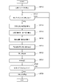
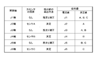
- FIG. 1 It is an overall block diagram of the robot system which incorporated the control device as the force detection device in one Embodiment of this invention. It is a functional block diagram of the robot system shown in FIG. It is a flowchart about the operation of the control device shown in FIG. It is a figure which shows an example of the torque detection method.
- FIG. 1 is an overall configuration diagram of a robot system 10 in which a control device 14 as a force detecting device according to an embodiment of the present invention is incorporated.
- the robot system 10 is a system for the robot 12 and the worker to work in cooperation with each other.
- the robot system 10 includes a robot 12 and a control device 14 that controls the drive of the robot 12.
- the robot 12 is a vertical joint type robot having a plurality of joint axes 20.
- the robot 12 has a swivel axis (J1 axis) for rotating the body, a lower arm axis (J2 axis) for moving the body back and forth, an upper arm axis (J3 axis) for moving the arm up and down, and an arm.
- It has a wrist swivel axis (J4 axis) for rotating the portion, a "wrist bending axis" (J5 axis) for swinging the wrist up and down, and a wrist rotation axis (J6 axis) for rotating the wrist.
- An end effector (not shown) is attached to the hand of the robot 12.
- a servomotor 22 (FIG. 2) that drives rotation through servo control is connected to each joint shaft 20.
- the robot 12 can independently drive a plurality of joint axes 20 in response to a command from the control device 14 to perform various operations including gripping / moving, welding, and painting of the work.
- the control device 14 is a computer that controls the robot 12. Specifically, the control device 14 includes a connector 30, a communication I / F 32, a processor 34, and a memory 36. The number of each component is one in the example of FIG. 1, but it may be two or more.
- the connector 30 is a terminal for electrically connecting to the robot 12 via a power cable or a communication cable (both not shown).
- the control device 14 supplies electric power and control signals to the robot 12 and acquires measurement signals from various sensors provided in the robot 12.
- the communication I / F 32 is an interface for communicating with an external device.
- the control device 14 can exchange data with, for example, a programming pendant, a work terminal, or a host device (all not shown).
- the processor 34 may be a general-purpose processor including a CPU (Central Processing Unit), or may be a dedicated processor including an FPGA (Field Programmable Gate Array) and a GPU (Graphics Processing Unit).
- the memory 36 is a non-transient storage medium and stores programs and data necessary for the processor 34 to control each component.
- FIG. 2 is a functional block diagram of the robot system 10 shown in FIG.
- the robot 12 includes the above-mentioned joint shaft 20, a servomotor 22, a position sensor 24, and a force sensor 26.
- the control device 14 includes a servo control unit 40, a measurement unit 42, an estimation unit 44, a correction unit 46, a dynamics calculation unit 48, and a determination unit 50.
- the servo motor 22 is a rotary actuator that rotates the joint shaft 20.
- the position sensor 24 outputs a detection signal (hereinafter, referred to as “position signal”) indicating the angular position of the servomotor 22.
- the force sensor 26 outputs a detection signal (hereinafter referred to as “force signal”) indicating the magnitude of the force acting on the joint axis 20.
- the force sensors 26 are provided only on n (1 ⁇ n ⁇ N) of the N joint axes 20 (N ⁇ 2).
- the reference numerals of the joint shaft 20 may be distinguished and described depending on whether or not the force sensor 26 is installed.
- the joint axis provided with the force sensor 26 is referred to as "joint axis 20a”
- the joint axis not provided with the force sensor 26 is referred to as "joint axis 20b”.
- the servo control unit 40 controls the drive of the servo motor 22 based on the position signal from the position sensor 24 (or encoder).
- PWM Pulse Width Modulation
- the current flowing through the servomotor 22 is the control amount is used.
- the measuring unit 42 measures the force acting on the joint axis 20a using the force sensor 26.
- the measuring unit 42 refers to the known detection characteristics of the force sensor 26 and converts the force signal from the force sensor 26 into a measured value of the force acting on the joint axis 20a.
- the measured value obtained by the measurement by the measuring unit 42 is obtained as the force detection result (hereinafter, also referred to as “first detected value”).
- the estimation unit 44 estimates the force acting on the joint shafts 20a and 20b based on the state quantity indicating the driving state of the servomotor 22.
- This "state quantity” is a physical quantity having a relatively high correlation with force, and examples thereof include current and voltage. Further, the state quantity may be an actually measured measured value or a control command value of the servomotor 22.
- the estimation unit 44 estimates the forces acting on the joint axes 20a and 20b, respectively, according to the estimation model specified by the estimation parameters.
- This estimation model is, for example, a model common to a plurality of joint axes 20, and describes a calculation rule in which the torque generated by the servomotor 22 is proportional to the magnitude of the current (hereinafter, current value).
- the "common model” means that the mathematical formula types of the model functions are the same or similar, and includes cases where the multipliers or constants are different.
- the correction unit 46 corrects the estimated value obtained by the estimation by the estimation unit 44 according to the calculation rule specified by the correction parameter.
- the correction unit 46 corrects the estimated value on the joint axis 20b by using the difference amount between the measured value and the estimated value on the joint axis 20a. This difference amount may be the difference between the measured value and the estimated value, or may be the ratio between the measured value and the estimated value.
- the estimated value corrected by the correction unit 46 is obtained as the force detection result (hereinafter, also referred to as “second detection value”).
- the correction unit 46 corrects the estimated value in the joint shaft 20b by using the difference amount in all or a part of the two or more joint shafts 20a.
- the difference amount may be calculated by statistical processing relating to a set of difference amounts corresponding to the plurality of joint axes 20a. This statistic may be either mean, maximum, minimum, mode, or median.
- the correction unit 46 corrects the estimated value in the joint shaft 20b by using the difference amount of the joint shaft 20a located immediately upstream or downstream.
- the difference amount may be calculated by a weighted sum of the difference amounts corresponding to the plurality of joint axes 20a.
- the weighting coefficient may be set to a larger value as the positions of the joint axes 20 are closer to each other, and to a smaller value as the positions of the joint axes 20 are farther from each other.
- the dynamics calculation unit 48 dynamically calculates the force acting on the joint axes 20a and 20b by the weight of the robot 12 or its own movement by using the position information and the dynamics parameters of the servomotor 22.
- the position information includes a position, a velocity, an acceleration, a jerk, and the like specified from the position signal or its temporal change.
- the dynamic parameters include the distance between the joint axes 20 and the crossing angle, the mass of the arm and the end effector, the position of the center of gravity, and the inertia. This parameter may be preset at the time of shipment from the factory, or may be set by the system maker or the user of the robot 12.
- the calculated value obtained by calculation is a force that acts during normal operation of the robot 12 under a situation where interference with an external object (including a worker) does not occur, and corresponds to a reference value in the determination by the determination unit 50. do.
- the determination unit 50 is [1] the first detection value from the measurement unit 42 and the calculation value from the dynamics calculation unit 48, or [2] the second detection value from the correction unit 46 and the estimation from the dynamics calculation unit 48.
- the value is used to determine if the robot 12 has interfered with an external object. For example, the determination unit 50 considers a value obtained by subtracting the calculated value from the detected value as an "external force", and determines whether or not the external force exceeds the threshold value.
- the determination unit 50 determines that the robot 12 has interfered with an external object when the external force exceeds the threshold value, and stops driving the servomotor 22 toward the corresponding servo control unit 40 or the brake mechanism (not shown). Output a stop signal.
- control device 14 The robot system 10 in this embodiment is configured as described above. Subsequently, the operation of the control device 14 constituting a part of the robot system 10 will be described with reference to the flowchart of FIG.
- step SP10 of FIG. 3 the processor 34 of the control device 14 sets the calculation parameters.
- the estimation unit 44 is set with the estimation parameter
- the correction unit 46 is set with the correction parameter
- the dynamics calculation unit 48 is set with the dynamics parameter.
- the estimation parameters correspond to M, L, and R of the equation (1) described later.
- the correction parameter corresponds to a parameter for specifying F in the equation (2) described later.
- step SP12 the processor 34 of the control device 14 confirms whether or not the execution timing of the determination process has arrived. If the execution timing has not yet arrived (step SP12: NO), the process remains in step SP12 until the timing arrives. On the other hand, when the execution timing has arrived (step SP12: YES), the process proceeds to the next step SP14.
- FIG. 4 is a diagram showing an example of a torque detection method.
- every other force sensor 26 is provided among the J1 to J6 axes.
- a sensor A is provided on the J2 axis
- a sensor B is provided on the J4 axis
- a sensor C is provided on the J6 axis.
- the first detection value is derived by measurement.
- the second detection value is derived by estimation and correction.
- step SP14 of FIG. 3 the measuring unit 42 acquires a force signal corresponding to the J2, J4, and J6 axes from the force sensor 26 provided in the robot 12.
- the estimation unit 44 acquires a current control command value (hereinafter referred to as “current value”) from the servo control unit 40 corresponding to the J1 to J6 axes.
- step SP18 the estimation unit 44 estimates the torque acting on the J1 to J6 axes by using the current value acquired in step SP14.
- the estimated value of torque is obtained according to the estimation model represented by the following equation (1).
- Te I x M x L x R ...
- I corresponds to the current value (unit: A).
- M corresponds to the torque constant (unit: N ⁇ m / A) of the servomotor 22.
- L corresponds to the mechanical loss coefficient (dimensionless quantity).
- R corresponds to a reduction ratio (dimensionless quantity).
- step SP20 the correction unit 46 corrects the estimated values in the J1, J3, and J5 axes obtained in step SP18.
- the estimated torque value is corrected according to the following equation (2).
- Tc Te ⁇ F ( ⁇ ) ⁇ ⁇ (2)
- Tc corresponds to the corrected estimated value (unit: Nm).
- F ( ⁇ ) is a function that returns the average value of the torque ratios belonging to the population. The number of samples used to calculate the average value may be all three or two or less.
- the measured values of all the sensors A, B, and C are used for the J1 axis, which is the most upstream side of the 6 axes.
- the robustness to the torque ratio may be increased and the variation in detection accuracy may be suppressed.
- the other J3 and J5 axes only the measured values of the most recent upstream and downstream sensors are used. Specifically, the measured values of the sensors A and B are used on the J3 axis, and the measured values of the sensors B and C are used on the J5 axis. By using only the torque ratio of the adjacent joint shafts 20a, the detection accuracy may be further improved.
- step SP22 the dynamics calculation unit 48 uses the position information and the dynamics parameters of the servomotor 22 on the joint axes 20a and 20b assuming a situation where interference does not occur between the robot 12 and an external object. Calculate the acting torque Td.
- step SP24 the determination unit 50 determines whether or not the robot 12 has interfered with an external object by using the detection value obtained in step SP16 or SP20 and the calculated value acquired in step SP22. Specifically, the determination unit 50 "interferes" when the value obtained by subtracting the calculated value (Td) from the detected value (Tm, Tc) exceeds the threshold value, and "no interference" when the value is equal to or less than the threshold value. Each is judged.
- step SP26 the determination unit 50 confirms whether or not there has been interference with an external object. If there is no interference (step SP26: NO), the process returns to step SP12, and the operations of steps SP12 to SP26 are repeated. On the other hand, if there is interference (step SP26: YES), the process proceeds to the next step SP28.
- step SP28 the determination unit 50 outputs a stop signal instructing the stop of the servomotor 22 to all the servo control units 40.
- the brake is activated and the robot 12 stops operating. After that, when the worker operates the recovery switch (not shown), the brake is released and the operation of the robot 12 is restarted.
- the robot system 10 includes a robot 12 including a plurality of joint axes 20 and a plurality of actuators (here, a servomotor 22) connected to each of the joint axes 20, and a robot.
- a force detecting device (here, a control device 14) for detecting an external force acting on the 12 is provided.
- the control device 14 estimates the force acting on the joint shaft 20 based on the measuring unit 42 that measures the force acting on the joint shaft 20 using the force sensor 26 and the state quantity indicating the driving state of the servomotor 22.
- a unit 44 and a correction unit 46 that corrects the estimated value obtained by the estimation by the estimation unit 44 are provided.
- the control device 14 obtains the measured value obtained by the measurement by the measuring unit 42 as the force detection result.
- the control device 14 obtains the estimated value corrected by the correction unit 46 as the force detection value.
- the correction unit 46 may correct the estimated value on the joint axis 20b by using the difference amount between the measured value and the estimated value on the joint axis 20a. Since the error relationship between the measured value and the estimated value on the joint axis 20a is reflected in the correction of the estimated value on the joint axis 20b, the force detection accuracy on the joint axis 20b is further improved.
- the estimation unit 44 may estimate the forces acting on the joint axes 20a and 20b according to a common estimation model, respectively. As a result, the tendency of the error peculiar to the estimation model can be appropriately corrected, and the accuracy of detecting the force on the joint axis 20b is further improved.
- the difference amount may be calculated by statistical processing regarding a set of difference amounts corresponding to two or more joint axes 20a. As a result, the robustness to the difference amount is increased, and the variation in the detection accuracy is suppressed.
- the correction unit 46 may correct the estimated value in the joint shaft 20b by using the difference amount of the joint shaft 20a located immediately upstream or downstream. .. By using the difference amount of the adjacent joint shafts 20a, the accuracy of detecting the force on the joint shafts 20b is further improved.
- the type of actuator is not limited to this.
- a rotary actuator other than the servomotor, a linear actuator, or a combination thereof may be used.
- the force sensors 26 are provided every other of the J1 to J6 axes, but the number, arrangement distribution, ratio, etc. of the force sensors 26 are not limited to this. Further, although all the joint axes provided with the force sensor 26 are classified as “first joint axes”, some of them may be classified as “second joint axes”. For example, it is assumed that the reliability of the measurement result is lowered due to the failure of the force sensor 26 or the deterioration of the performance.
- a temperature sensor may be provided around the position sensor 24 or the force sensor 26, and a temperature compensation function may be incorporated for the above estimation or correction.
- step SP22 may be excluded from the flowchart of FIG. 3, and the determination unit 50 may determine the presence or absence of interference using the most recently calculated calculated value.
- the force detecting device is provided integrally with the control device 14 of the robot 12
- the device configuration is not limited to this.
- the force detecting device may be a computer separate from the control device, or may be provided integrally with the robot.
- a 6-axis vertical articulated robot has been described as an example, but the type of the robot 12 is not limited to this.
- the robot 12 may be any of a 7-axis robot, a horizontal articulated robot (so-called SCARA robot), a parallel link robot, or an orthogonal robot (so-called gantry robot).
- SCARA robot horizontal articulated robot
- gantry robot orthogonal robot
- the present invention is not limited to industrial robots, and can be applied to various movable devices having a plurality of joint axes 20.
Landscapes
- Engineering & Computer Science (AREA)
- Robotics (AREA)
- Mechanical Engineering (AREA)
- Physics & Mathematics (AREA)
- General Physics & Mathematics (AREA)
- Human Computer Interaction (AREA)
- Manipulator (AREA)
Abstract
Description
<全体構成>
図1は、本発明の一実施形態における力検出装置としての制御装置14が組み込まれたロボットシステム10の全体構成図である。ロボットシステム10は、ロボット12及び作業員が協調して作業を行うためのシステムである。このロボットシステム10は、具体的には、ロボット12と、当該ロボット12の駆動制御を司る制御装置14と、を含んで構成される。
図2は、図1に示すロボットシステム10の機能ブロック図である。ロボット12は、上記した関節軸20と、サーボモータ22と、位置センサ24と、力センサ26と、を備える。制御装置14は、サーボ制御部40と、測定部42と、推定部44と、補正部46と、動力学演算部48と、判定部50と、を備える。
この実施形態におけるロボットシステム10は、以上のように構成される。続いて、このロボットシステム10の一部を構成する制御装置14の動作について、図3のフローチャートを参照しながら説明する。
Te=I×M×L×R ・・(1)
ここで、Teは、トルクの推定値(単位:N・m)に相当する。Iは、電流値(単位:A)に相当する。Mは、サーボモータ22のトルク定数(単位:N・m/A)に相当する。Lは、機械的損失係数(無次元量)に相当する。Rは、減速比(無次元量)に相当する。
Tc=Te×F({Δ}) ・・(2)
ここで、Tcは、補正済みの推定値(単位:N・m)に相当する。{Δ}は、J2,J4,J6軸におけるトルク比(=Te/Tm)の母集団に相当する。F(・)は、母集団に属するトルク比の平均値を返す関数である。平均値の算出に用いられる標本数は、3個すべてであってもよいし、2個以下であってもよい。
以上のように、ロボットシステム10は、複数の関節軸20と、関節軸20のそれぞれに接続される複数のアクチュエータ(ここでは、サーボモータ22)と、を含んで構成されるロボット12と、ロボット12に作用する外力を検出する力検出装置(ここでは、制御装置14)と、を備える。制御装置14は、力センサ26を用いて関節軸20に作用する力を測定する測定部42と、サーボモータ22の駆動状態を示す状態量に基づいて関節軸20に作用する力を推定する推定部44と、推定部44による推定にて得られた推定値を補正する補正部46と、を備える。
なお、本発明は、上記した実施形態に限定されるものではなく、この発明の主旨を逸脱しない範囲で自由に変更できることは勿論である。あるいは、技術的に矛盾が生じない範囲で各々の構成を任意に組み合わせてもよい。あるいは、技術的に矛盾が生じない範囲でフローチャートにおける各ステップの実行順番を変更してもよい。
10…ロボットシステム、12…ロボット、14…制御装置(力検出装置)、20,20a,20b…関節軸、22…サーボモータ(アクチュエータ)、24‥位置センサ、26‥力センサ、40‥サーボ制御部、42‥推定部、44‥測定部、46‥補正部、48‥動力学演算部、50‥判定部
Claims (6)
- 複数の関節軸と、該関節軸のそれぞれに接続される複数のアクチュエータと、を含んで構成されるロボットに作用する力を検出する力検出装置であって、
力センサを用いて前記関節軸に作用する力を測定する測定部と、
前記アクチュエータの駆動状態を示す状態量に基づいて前記関節軸に作用する力を推定する推定部と、
前記推定部による推定にて得られた推定値を補正する補正部と、
を備え、
前記複数の関節軸のうち前記力センサが設けられる第一関節軸の場合、前記測定部による測定にて得られた測定値を力の検出結果として求め、
前記複数の関節軸のうち前記力センサが設けられない第二関節軸の場合、前記補正部により補正された推定値を力の検出値として求める、力検出装置。 - 前記補正部は、前記第一関節軸における前記測定値と前記推定値の間の差分量を用いて、前記第二関節軸における前記推定値を補正する、
請求項1に記載の力検出装置。 - 前記推定部は、共通する推定モデルに従って、前記第一関節軸及び前記第二関節軸に作用する力をそれぞれ推定する、
請求項2に記載の力検出装置。 - 前記差分量は、二以上の第一関節軸に対応する前記差分量の集合に関する統計処理により算出される、
請求項2又は3に記載の力検出装置。 - 前記補正部は、前記複数の関節軸が直列的に接続される場合、直近の上流又は下流にある第一関節軸の前記差分量を用いて、前記第二関節軸における前記推定値を補正する、
請求項2~4のいずれか1項に記載の力検出装置。 - 複数の関節軸と、前記関節軸のそれぞれに接続される複数のアクチュエータと、を含んで構成されるロボットと、
請求項1~5のいずれか1項に記載の力検出装置と、
を備える、ロボットシステム。
Priority Applications (4)
| Application Number | Priority Date | Filing Date | Title |
|---|---|---|---|
| CN202180079591.4A CN116685448A (zh) | 2020-11-27 | 2021-09-02 | 一种力检测装置及机器人系统 |
| JP2022565067A JP7695565B2 (ja) | 2020-11-27 | 2021-09-02 | 力検出装置及びロボットシステム |
| US18/254,440 US20240058956A1 (en) | 2020-11-27 | 2021-09-02 | Force detection device and robot system |
| EP21897440.0A EP4252981A4 (en) | 2020-11-27 | 2021-09-02 | FORCE SENSING DEVICE AND ROBOT SYSTEM |
Applications Claiming Priority (2)
| Application Number | Priority Date | Filing Date | Title |
|---|---|---|---|
| JP2020196932 | 2020-11-27 | ||
| JP2020-196932 | 2020-11-27 |
Publications (1)
| Publication Number | Publication Date |
|---|---|
| WO2022113462A1 true WO2022113462A1 (ja) | 2022-06-02 |
Family
ID=81754460
Family Applications (1)
| Application Number | Title | Priority Date | Filing Date |
|---|---|---|---|
| PCT/JP2021/032243 Ceased WO2022113462A1 (ja) | 2020-11-27 | 2021-09-02 | 力検出装置及びロボットシステム |
Country Status (5)
| Country | Link |
|---|---|
| US (1) | US20240058956A1 (ja) |
| EP (1) | EP4252981A4 (ja) |
| JP (1) | JP7695565B2 (ja) |
| CN (1) | CN116685448A (ja) |
| WO (1) | WO2022113462A1 (ja) |
Families Citing this family (1)
| Publication number | Priority date | Publication date | Assignee | Title |
|---|---|---|---|---|
| CN117444965A (zh) * | 2023-10-30 | 2024-01-26 | 朗宇芯科技(佛山)有限公司 | 一种机械手臂路线自动修正方法 |
Citations (5)
| Publication number | Priority date | Publication date | Assignee | Title |
|---|---|---|---|---|
| JP2012176465A (ja) | 2011-02-28 | 2012-09-13 | Univ Of Tokyo | トルクセンサ校正装置、校正方法、及びプログラム |
| US20190217464A1 (en) * | 2018-01-17 | 2019-07-18 | Ubtech Robotics Corp | Method for controlling walking of robot and robot |
| JP2020101541A (ja) * | 2018-12-21 | 2020-07-02 | ピルツ ゲーエムベーハー アンド コー.カーゲー | トルク推定のための方法および装置 |
| JP2020104249A (ja) | 2018-12-27 | 2020-07-09 | ファナック株式会社 | 産業用ロボットシステム |
| JP2020179483A (ja) * | 2019-04-26 | 2020-11-05 | ファナック株式会社 | ロボット |
Family Cites Families (8)
| Publication number | Priority date | Publication date | Assignee | Title |
|---|---|---|---|---|
| CN104379308B (zh) | 2012-06-29 | 2016-05-18 | 三菱电机株式会社 | 机器人控制装置以及机器人控制方法 |
| JP6193816B2 (ja) * | 2014-06-20 | 2017-09-06 | ファナック株式会社 | アームの退避機能を有する多関節ロボット |
| TWI642523B (zh) | 2017-09-21 | 2018-12-01 | 上銀科技股份有限公司 | 用於機械臂之負載估測重力補償的方法及其負載估測重力補償系統 |
| US11691293B2 (en) * | 2018-08-31 | 2023-07-04 | Fanuc Corporation | Robot |
| JP6841802B2 (ja) * | 2018-08-31 | 2021-03-10 | ファナック株式会社 | ロボットおよびロボットシステム |
| US11618163B2 (en) * | 2018-12-27 | 2023-04-04 | Fanuc Corporation | Industrial robot system |
| US12214488B2 (en) * | 2019-09-03 | 2025-02-04 | Shanghai Flexiv Robotics Technology Co., Ltd. | Robotic arm and robot |
| CN111683796A (zh) * | 2019-09-03 | 2020-09-18 | 上海非夕机器人科技有限公司 | 机械臂和机器人 |
-
2021
- 2021-09-02 US US18/254,440 patent/US20240058956A1/en active Pending
- 2021-09-02 EP EP21897440.0A patent/EP4252981A4/en not_active Withdrawn
- 2021-09-02 CN CN202180079591.4A patent/CN116685448A/zh active Pending
- 2021-09-02 WO PCT/JP2021/032243 patent/WO2022113462A1/ja not_active Ceased
- 2021-09-02 JP JP2022565067A patent/JP7695565B2/ja active Active
Patent Citations (5)
| Publication number | Priority date | Publication date | Assignee | Title |
|---|---|---|---|---|
| JP2012176465A (ja) | 2011-02-28 | 2012-09-13 | Univ Of Tokyo | トルクセンサ校正装置、校正方法、及びプログラム |
| US20190217464A1 (en) * | 2018-01-17 | 2019-07-18 | Ubtech Robotics Corp | Method for controlling walking of robot and robot |
| JP2020101541A (ja) * | 2018-12-21 | 2020-07-02 | ピルツ ゲーエムベーハー アンド コー.カーゲー | トルク推定のための方法および装置 |
| JP2020104249A (ja) | 2018-12-27 | 2020-07-09 | ファナック株式会社 | 産業用ロボットシステム |
| JP2020179483A (ja) * | 2019-04-26 | 2020-11-05 | ファナック株式会社 | ロボット |
Non-Patent Citations (1)
| Title |
|---|
| See also references of EP4252981A4 |
Also Published As
| Publication number | Publication date |
|---|---|
| CN116685448A (zh) | 2023-09-01 |
| US20240058956A1 (en) | 2024-02-22 |
| JPWO2022113462A1 (ja) | 2022-06-02 |
| EP4252981A1 (en) | 2023-10-04 |
| EP4252981A4 (en) | 2025-02-26 |
| JP7695565B2 (ja) | 2025-06-19 |
Similar Documents
| Publication | Publication Date | Title |
|---|---|---|
| JP7719155B2 (ja) | ロボットシステム、制御方法、物品の製造方法、制御プログラム、記録媒体 | |
| KR101548945B1 (ko) | 탄성 로봇 구조를 위한 운동 제어기 | |
| US11298828B2 (en) | Calibration device, calibration method, and control device | |
| TWI642523B (zh) | 用於機械臂之負載估測重力補償的方法及其負載估測重力補償系統 | |
| US10690558B2 (en) | Robot collision detection method | |
| US9517556B2 (en) | Robot control apparatus and robot control method | |
| EP3623113A1 (en) | Obtaining the gear stiffness of a robot joint gear of a robot arm | |
| US20100168919A1 (en) | Control method and control system for manipulator | |
| CN110871456B (zh) | 机器人 | |
| JP6044511B2 (ja) | ロボットの制御方法及びロボットシステム | |
| US20240009843A1 (en) | Method and computing system for determining a value of an error parameter indicative of quality of robot calibration | |
| US8543239B2 (en) | Robot control apparatus | |
| JP2016198828A (ja) | ロボット制御方法、ロボット装置、プログラム及び記録媒体 | |
| CN104908047A (zh) | 感知与外部环境的接触的机器人控制装置 | |
| JP2020101541A (ja) | トルク推定のための方法および装置 | |
| JP2012176465A (ja) | トルクセンサ校正装置、校正方法、及びプログラム | |
| JP2017124455A (ja) | ロボット装置、ロボット制御方法、プログラム及び記録媒体 | |
| US20200122318A1 (en) | Control system, control method, and control program | |
| WO2022113462A1 (ja) | 力検出装置及びロボットシステム | |
| KR101086364B1 (ko) | 칼만 필터를 이용한 로봇 기구학 변수 추정 방법 및 시스템 | |
| JP4168816B2 (ja) | ロボットの制御装置 | |
| JP6565622B2 (ja) | ロボットシステム及びロボット制御方法 | |
| CN109773827A (zh) | 用于机械臂的负载估测重力补偿的方法及其系统 | |
| JP6943906B2 (ja) | ロボット | |
| JP5473889B2 (ja) | 力制御装置 |
Legal Events
| Date | Code | Title | Description |
|---|---|---|---|
| 121 | Ep: the epo has been informed by wipo that ep was designated in this application |
Ref document number: 21897440 Country of ref document: EP Kind code of ref document: A1 |
|
| ENP | Entry into the national phase |
Ref document number: 2022565067 Country of ref document: JP Kind code of ref document: A |
|
| WWE | Wipo information: entry into national phase |
Ref document number: 18254440 Country of ref document: US |
|
| WWE | Wipo information: entry into national phase |
Ref document number: 202180079591.4 Country of ref document: CN |
|
| NENP | Non-entry into the national phase |
Ref country code: DE |
|
| ENP | Entry into the national phase |
Ref document number: 2021897440 Country of ref document: EP Effective date: 20230627 |
|
| WWW | Wipo information: withdrawn in national office |
Ref document number: 2021897440 Country of ref document: EP |