WO2022113908A1 - 光学装置および3次元造形装置 - Google Patents
光学装置および3次元造形装置 Download PDFInfo
- Publication number
- WO2022113908A1 WO2022113908A1 PCT/JP2021/042660 JP2021042660W WO2022113908A1 WO 2022113908 A1 WO2022113908 A1 WO 2022113908A1 JP 2021042660 W JP2021042660 W JP 2021042660W WO 2022113908 A1 WO2022113908 A1 WO 2022113908A1
- Authority
- WO
- WIPO (PCT)
- Prior art keywords
- light
- diffraction beam
- reflection surface
- guide path
- introduction
- Prior art date
- Legal status (The legal status is an assumption and is not a legal conclusion. Google has not performed a legal analysis and makes no representation as to the accuracy of the status listed.)
- Ceased
Links
Images




Classifications
-
- G—PHYSICS
- G02—OPTICS
- G02B—OPTICAL ELEMENTS, SYSTEMS OR APPARATUS
- G02B27/00—Optical systems or apparatus not provided for by any of the groups G02B1/00 - G02B26/00, G02B30/00
- G02B27/42—Diffraction optics, i.e. systems including a diffractive element being designed for providing a diffractive effect
- G02B27/4233—Diffraction optics, i.e. systems including a diffractive element being designed for providing a diffractive effect having a diffractive element [DOE] contributing to a non-imaging application
- G02B27/425—Diffraction optics, i.e. systems including a diffractive element being designed for providing a diffractive effect having a diffractive element [DOE] contributing to a non-imaging application in illumination systems
-
- B—PERFORMING OPERATIONS; TRANSPORTING
- B23—MACHINE TOOLS; METAL-WORKING NOT OTHERWISE PROVIDED FOR
- B23K—SOLDERING OR UNSOLDERING; WELDING; CLADDING OR PLATING BY SOLDERING OR WELDING; CUTTING BY APPLYING HEAT LOCALLY, e.g. FLAME CUTTING; WORKING BY LASER BEAM
- B23K26/00—Working by laser beam, e.g. welding, cutting or boring
- B23K26/02—Positioning or observing the workpiece, e.g. with respect to the point of impact; Aligning, aiming or focusing the laser beam
- B23K26/06—Shaping the laser beam, e.g. by masks or multi-focusing
- B23K26/064—Shaping the laser beam, e.g. by masks or multi-focusing by means of optical elements, e.g. lenses, mirrors or prisms
- B23K26/0643—Shaping the laser beam, e.g. by masks or multi-focusing by means of optical elements, e.g. lenses, mirrors or prisms comprising mirrors
-
- B—PERFORMING OPERATIONS; TRANSPORTING
- B22—CASTING; POWDER METALLURGY
- B22F—WORKING METALLIC POWDER; MANUFACTURE OF ARTICLES FROM METALLIC POWDER; MAKING METALLIC POWDER; APPARATUS OR DEVICES SPECIALLY ADAPTED FOR METALLIC POWDER
- B22F12/00—Apparatus or devices specially adapted for additive manufacturing; Auxiliary means for additive manufacturing; Combinations of additive manufacturing apparatus or devices with other processing apparatus or devices
- B22F12/20—Cooling means
-
- B—PERFORMING OPERATIONS; TRANSPORTING
- B22—CASTING; POWDER METALLURGY
- B22F—WORKING METALLIC POWDER; MANUFACTURE OF ARTICLES FROM METALLIC POWDER; MAKING METALLIC POWDER; APPARATUS OR DEVICES SPECIALLY ADAPTED FOR METALLIC POWDER
- B22F12/00—Apparatus or devices specially adapted for additive manufacturing; Auxiliary means for additive manufacturing; Combinations of additive manufacturing apparatus or devices with other processing apparatus or devices
- B22F12/40—Radiation means
- B22F12/44—Radiation means characterised by the configuration of the radiation means
-
- B—PERFORMING OPERATIONS; TRANSPORTING
- B23—MACHINE TOOLS; METAL-WORKING NOT OTHERWISE PROVIDED FOR
- B23K—SOLDERING OR UNSOLDERING; WELDING; CLADDING OR PLATING BY SOLDERING OR WELDING; CUTTING BY APPLYING HEAT LOCALLY, e.g. FLAME CUTTING; WORKING BY LASER BEAM
- B23K26/00—Working by laser beam, e.g. welding, cutting or boring
- B23K26/02—Positioning or observing the workpiece, e.g. with respect to the point of impact; Aligning, aiming or focusing the laser beam
- B23K26/06—Shaping the laser beam, e.g. by masks or multi-focusing
- B23K26/064—Shaping the laser beam, e.g. by masks or multi-focusing by means of optical elements, e.g. lenses, mirrors or prisms
-
- B—PERFORMING OPERATIONS; TRANSPORTING
- B23—MACHINE TOOLS; METAL-WORKING NOT OTHERWISE PROVIDED FOR
- B23K—SOLDERING OR UNSOLDERING; WELDING; CLADDING OR PLATING BY SOLDERING OR WELDING; CUTTING BY APPLYING HEAT LOCALLY, e.g. FLAME CUTTING; WORKING BY LASER BEAM
- B23K26/00—Working by laser beam, e.g. welding, cutting or boring
- B23K26/02—Positioning or observing the workpiece, e.g. with respect to the point of impact; Aligning, aiming or focusing the laser beam
- B23K26/06—Shaping the laser beam, e.g. by masks or multi-focusing
- B23K26/067—Dividing the beam into multiple beams, e.g. multi-focusing
-
- B—PERFORMING OPERATIONS; TRANSPORTING
- B23—MACHINE TOOLS; METAL-WORKING NOT OTHERWISE PROVIDED FOR
- B23K—SOLDERING OR UNSOLDERING; WELDING; CLADDING OR PLATING BY SOLDERING OR WELDING; CUTTING BY APPLYING HEAT LOCALLY, e.g. FLAME CUTTING; WORKING BY LASER BEAM
- B23K26/00—Working by laser beam, e.g. welding, cutting or boring
- B23K26/34—Laser welding for purposes other than joining
-
- B—PERFORMING OPERATIONS; TRANSPORTING
- B23—MACHINE TOOLS; METAL-WORKING NOT OTHERWISE PROVIDED FOR
- B23K—SOLDERING OR UNSOLDERING; WELDING; CLADDING OR PLATING BY SOLDERING OR WELDING; CUTTING BY APPLYING HEAT LOCALLY, e.g. FLAME CUTTING; WORKING BY LASER BEAM
- B23K26/00—Working by laser beam, e.g. welding, cutting or boring
- B23K26/34—Laser welding for purposes other than joining
- B23K26/342—Build-up welding
-
- B—PERFORMING OPERATIONS; TRANSPORTING
- B29—WORKING OF PLASTICS; WORKING OF SUBSTANCES IN A PLASTIC STATE IN GENERAL
- B29C—SHAPING OR JOINING OF PLASTICS; SHAPING OF MATERIAL IN A PLASTIC STATE, NOT OTHERWISE PROVIDED FOR; AFTER-TREATMENT OF THE SHAPED PRODUCTS, e.g. REPAIRING
- B29C64/00—Additive manufacturing, i.e. manufacturing of three-dimensional [3D] objects by additive deposition, additive agglomeration or additive layering, e.g. by 3D printing, stereolithography or selective laser sintering
- B29C64/20—Apparatus for additive manufacturing; Details thereof or accessories therefor
- B29C64/264—Arrangements for irradiation
- B29C64/268—Arrangements for irradiation using laser beams; using electron beams [EB]
-
- B—PERFORMING OPERATIONS; TRANSPORTING
- B29—WORKING OF PLASTICS; WORKING OF SUBSTANCES IN A PLASTIC STATE IN GENERAL
- B29C—SHAPING OR JOINING OF PLASTICS; SHAPING OF MATERIAL IN A PLASTIC STATE, NOT OTHERWISE PROVIDED FOR; AFTER-TREATMENT OF THE SHAPED PRODUCTS, e.g. REPAIRING
- B29C64/00—Additive manufacturing, i.e. manufacturing of three-dimensional [3D] objects by additive deposition, additive agglomeration or additive layering, e.g. by 3D printing, stereolithography or selective laser sintering
- B29C64/20—Apparatus for additive manufacturing; Details thereof or accessories therefor
- B29C64/264—Arrangements for irradiation
- B29C64/286—Optical filters, e.g. masks
-
- B—PERFORMING OPERATIONS; TRANSPORTING
- B33—ADDITIVE MANUFACTURING TECHNOLOGY
- B33Y—ADDITIVE MANUFACTURING, i.e. MANUFACTURING OF THREE-DIMENSIONAL [3D] OBJECTS BY ADDITIVE DEPOSITION, ADDITIVE AGGLOMERATION OR ADDITIVE LAYERING, e.g. BY 3D PRINTING, STEREOLITHOGRAPHY OR SELECTIVE LASER SINTERING
- B33Y30/00—Apparatus for additive manufacturing; Details thereof or accessories therefor
-
- G—PHYSICS
- G02—OPTICS
- G02B—OPTICAL ELEMENTS, SYSTEMS OR APPARATUS
- G02B27/00—Optical systems or apparatus not provided for by any of the groups G02B1/00 - G02B26/00, G02B30/00
- G02B27/09—Beam shaping, e.g. changing the cross-sectional area, not otherwise provided for
- G02B27/0938—Using specific optical elements
- G02B27/0988—Diaphragms, spatial filters, masks for removing or filtering a part of the beam
-
- G—PHYSICS
- G02—OPTICS
- G02B—OPTICAL ELEMENTS, SYSTEMS OR APPARATUS
- G02B5/00—Optical elements other than lenses
- G02B5/003—Light absorbing elements
-
- G—PHYSICS
- G02—OPTICS
- G02B—OPTICAL ELEMENTS, SYSTEMS OR APPARATUS
- G02B5/00—Optical elements other than lenses
- G02B5/005—Diaphragms
- G02B5/006—Diaphragms cooled
-
- B—PERFORMING OPERATIONS; TRANSPORTING
- B22—CASTING; POWDER METALLURGY
- B22F—WORKING METALLIC POWDER; MANUFACTURE OF ARTICLES FROM METALLIC POWDER; MAKING METALLIC POWDER; APPARATUS OR DEVICES SPECIALLY ADAPTED FOR METALLIC POWDER
- B22F10/00—Additive manufacturing of workpieces or articles from metallic powder
- B22F10/20—Direct sintering or melting
- B22F10/28—Powder bed fusion, e.g. selective laser melting [SLM] or electron beam melting [EBM]
-
- B—PERFORMING OPERATIONS; TRANSPORTING
- B22—CASTING; POWDER METALLURGY
- B22F—WORKING METALLIC POWDER; MANUFACTURE OF ARTICLES FROM METALLIC POWDER; MAKING METALLIC POWDER; APPARATUS OR DEVICES SPECIALLY ADAPTED FOR METALLIC POWDER
- B22F12/00—Apparatus or devices specially adapted for additive manufacturing; Auxiliary means for additive manufacturing; Combinations of additive manufacturing apparatus or devices with other processing apparatus or devices
- B22F12/40—Radiation means
- B22F12/49—Scanners
Definitions
- the present invention relates to an optical device that irradiates an irradiation surface on an object with a modulated beam, and a three-dimensional modeling device including the optical device.
- an SLM (Selective Laser Melting) type three-dimensional molding device that performs three-dimensional molding by irradiating a molding material such as metal powder with a modulated laser beam and melting the molding material has been used.
- a three-dimensional modeling device for example, an optical device that modulates a laser beam with a diffractive light modulator to irradiate a modeling material is used.
- the 0th-order diffraction beam from the light modulator is guided to the modeling material, and the high-order diffraction beam such as the first-order diffraction beam that is not irradiated on the modeling material is generated by the light-shielding portion provided in the optical device. It is shaded.
- the light-shielding portion is usually provided in the vicinity of the focusing position of the primary diffraction beam or the like in order to suppress the increase in size of the light-shielding portion and the optical device.
- Such an optical device is also used in a pattern drawing device that draws a pattern by irradiating a substrate with a laser beam, and the pattern drawing device of International Publication No. 2018/150996 (Reference 1) draws a pattern.
- An absorber that absorbs a diffracted beam that is not used in the head is provided in the head. As shown in FIG. 3 of Document 1, if the absorber TR is arranged away from other optical elements such as a reflection mirror, the optical device becomes large.
- the power density of the laser light increases, the amount of heat converted from the laser light increases in the part that blocks or absorbs the diffracted beam, such as the light-shielding part, and the waste heat cannot be kept in time, so that the temperature of the light-shielding part becomes locally high. It may rise and damage the light-shielding part.
- the temperature of the light-shielding portion rises, the temperature of surrounding parts also rises, which may reduce the irradiation accuracy of the laser beam.
- the scattered light that cannot be completely absorbed by the light-shielding portion and leaks to the surroundings raises the temperature of the surrounding parts, which may lower the irradiation accuracy of the laser beam.
- the present invention is aimed at an optical device that irradiates an object with modulated light, and an object thereof is to suppress leakage of light from a light-shielding unit to the outside and to suppress a temperature rise of the light-shielding unit.
- the optical device modulates an illumination optical system that shapes a laser beam emitted from a laser light source into a predetermined shape and the laser beam shaped by the illumination optical system into a modulated beam. It includes an optical modulator and a projection optical system that guides the modulated beam to an object.
- the projection optical system includes a light-shielding unit that passes a 0th-order diffraction beam from the light modulator and blocks the 1st-order diffraction beam.
- the light-shielding unit is located near the focusing position of the 0th-order diffraction beam on the optical axis of the 0th-order diffraction beam, has a 0th-order diffraction beam aperture through which the 0th-order diffraction beam passes, and the light of the first-order diffraction beam. Located on the axis near the focusing position of the primary diffractive beam and near the aperture of the 0th order diffractive beam, in a direction deviating from the incident direction of the primary diffractive beam and away from the optical axis of the 0th order diffractive beam.
- a light guide path having an introduction reflecting surface that reflects the primary diffraction beam and an introduction port into which light from the introduction reflection surface is incident, and surrounded by a light-shielding member to guide the light introduced from the introduction port. And an absorption unit that absorbs the light guided while being diffused by the light guide path.
- the present invention it is possible to suppress the leakage of light from the light-shielding unit to the outside, and it is also possible to suppress the temperature rise of the light-shielding unit.
- the introduction reflection surface is a mirror surface
- the light guide path is provided with a scattering reflection surface that reflects and guides the light from the introduction reflection surface while scattering it.
- the scattering reflection surface has linear fine irregularities extending along a plane parallel to both the depth direction to the scattering reflection surface and the depth direction from the scattering reflection surface in the light guide path.
- the introduction reflecting surface is arranged on the optical axis of the primary diffraction beam toward the front side of the focusing position of the primary diffraction beam, and the light from the introduction reflection surface is directly directed to the light guide path.
- the primary diffraction beam is focused between the incident reflecting surface and the introduced reflecting surface.
- the light-absorbing portion includes an uneven surface on which a light-absorbing film is provided on the surface.
- the light-shielding unit is arranged in the vicinity of the light-absorbing portion and further includes a cooling flow path through which the refrigerant flows.
- a cooling flow path through which the refrigerant flows is arranged also in the vicinity of the light guide path.
- the second-order diffraction from the light modulator is performed on an outer surface extending in a direction perpendicular to the optical axis of the 0th-order diffraction beam around the 0th-order diffraction beam aperture and the introduction reflection surface.
- a secondary absorption unit that absorbs the beam is provided.
- the light guide path extends parallel to the plane perpendicular to the optical axis of the 0th order diffractive beam.
- the light guide path extends while bending around the 0th-order diffraction beam opening and surrounds the 0th-order diffraction beam opening.
- the introduced reflective surface surrounds the periphery of the 0th-order diffractive beam opening and has a circumferential inclination away from the optical axis of the 0th-order diffractive beam as it goes from the front side to the back side in the optical axis direction of the 0th-order diffractive beam. It is part of the surface.
- the light guide path is a part of an annular space that radiates outward from the circumferential inclined surface.
- the 0th-order diffractive beam and the 1st-order diffractive beam are planar beams that spread in the vertical direction.
- the light guide path includes a pair of reflective surfaces parallel to each other extending in a direction inclined with respect to the optical axis of the 0th-order diffracted beam and in a vertical direction.
- the introduced reflecting surface is an end portion of one of the pair of reflecting surfaces on the side close to the 0th-order diffracted beam. The light from the introduced reflecting surface is guided in the light guide path while reciprocating between the pair of reflecting surfaces.
- the introduction reflective surface and the light guide path are provided in one cutting block formed by cutting.
- the shading unit blocks a plurality of primary diffraction beams from the light modulator.
- the light-shielding unit includes a plurality of light-shielding portions corresponding to the plurality of primary diffracted beams. Each light-shielding portion includes the introduction reflective surface and the light guide path. The relative positions of the plurality of light-shielding portions with respect to the 0th-order diffraction beam aperture are variable.
- the present invention is also directed to a three-dimensional modeling apparatus.
- the three-dimensional modeling apparatus includes the above-mentioned optical apparatus, a laser light source that emits the laser beam to the optical apparatus, and the object to which the modulated beam from the optical apparatus is irradiated. It is an object and includes a scanning unit that scans the modulated beam on the modeling material.
- FIG. 1 It is a figure which shows the structure of the 3D modeling apparatus which comprises the optical apparatus which concerns on 1st Embodiment. It is a figure which shows the structure of a projection optical system. It is a figure which shows the structure of a projection optical system. It is a perspective view of a light-shielding unit. It is a perspective view which shows the inside of a light-shielding unit. It is a front view of a shading unit. It is a perspective view which shows the inside of a light-shielding unit. It is a front view which shows the one light-shielding part enlarged. It is a perspective view which shows the 1st internal reflection surface enlarged. It is a front view of the 3rd member.
- FIG. 1 is a diagram showing a configuration of a three-dimensional modeling apparatus 1 including an optical apparatus 12 according to the first embodiment of the present invention.
- the three-dimensional molding apparatus 1 is an SLM (Selective Laser Melting) type three-dimensional molding apparatus that performs three-dimensional molding by irradiating a powdered or pasted molding material with a modulated laser beam and melting the molding material.
- SLM Selective Laser Melting
- the modeling material is, for example, metal, engineering plastic, ceramics, synthetic resin, or the like.
- the modeling material may include a plurality of types of materials.
- the three-dimensional modeling device 1 includes a laser light source 11, an optical device 12, a scanning unit 13, and a material supply mechanism 14.
- the laser beam L31 emitted from the laser light source 11 is guided to the scanning unit 13 by the optical device 12, and the scanning unit 13 is placed on the modeling material 91 in the modeling space 140 of the material supply mechanism 14. Is scanned at. As a result, the portion of the modeling material 91 irradiated with the laser beam is melted. Then, the three-dimensional model is formed by repeatedly supplying the modeling material 91 to the modeling space 140 and scanning the laser beam on the modeling material 91.
- each configuration of the optical device 12 is surrounded by a two-dot chain line.
- the laser light source 11, the optical device 12 (for example, the light modulator 22 described later), and the scanning unit are based on the design data (for example, CAD data) of the three-dimensional model to be manufactured.
- the configuration of the 13 and the material supply mechanism 14 and the like is controlled by a control unit (not shown).
- the control unit is, for example, a normal computer including a processor, a memory, an input / output unit, and a bus.
- the laser light source 11 emits the laser beam L31 to the optical device 12.
- the laser light source 11 is, for example, a fiber laser light source.
- the wavelength of the laser beam L31 is, for example, 1.070 ⁇ m.
- the optical device 12 modulates the laser beam L31 from the laser light source 11 into the modulated beam L33 and irradiates the scanning unit 13.
- the optical device 12 includes an illumination optical system 21, an optical modulator 22, and a projection optical system 23.
- the illumination optical system 21 and the projection optical system 23 each include a plurality of optical elements such as lenses, as will be described later.
- the illumination optical system 21 shapes the laser beam L31 from the laser light source 11 into a predetermined shape and guides it to the light modulator 22.
- the illumination optical system 21 shapes the laser beam L31 into a substantially linear parallel beam L32 that is long in one direction (hereinafter, referred to as “long-axis direction”) into the light modulator 22.
- the cross-sectional shape of the parallel beam L32 is a substantially linear shape that is long in the long axis direction and short in the short axis direction perpendicular to the long axis direction.
- the cross-sectional shape of the parallel beam L32 is the shape of the parallel beam L32 on a plane perpendicular to the traveling direction of the parallel beam L32.
- the cross section of light means the cross section of the light in a plane perpendicular to the traveling direction of the light, as described above.
- the cross-sectional shape of the parallel beam L32 can also be regarded as a substantially rectangular shape.
- the size of the cross section of the parallel beam L32 is the same at any position in the traveling direction of the parallel beam L32.
- the shape of the irradiation region of the parallel beam L32 on the light modulator 22 is, for example, a substantially linear shape (or a substantially rectangular shape) having a length of 28 mm in the major axis direction and a length of 1 mm in the minor axis direction.
- the light modulator 22 modulates the parallel beam L32 from the illumination optical system 21 into the modulated beam L33 and guides it to the projection optical system 23.
- the light modulator 22 for example, GLV (Grating Light Valve) (registered trademark), which is a one-dimensional spatial light modulation element, can be used.
- the light modulator 22 includes a plurality of modulation elements (not shown) arranged in a direction corresponding to the major axis direction of the parallel beam L32. Each modulation element comprises a plurality of ribbons arranged adjacent to each other.
- light modulation using a diffraction grating is performed, and the reflected light from each modulation element is switched between a 0th-order diffracted beam (that is, specular reflected light) and a non-0th-order diffracted beam.
- the 0th-order diffracted beam emitted from the light modulator 22 is guided to the scanning unit 13 by the projection optical system 23. Further, the non-zero-order diffraction beam emitted from the light modulator 22 is blocked and absorbed in front of the scanning unit 13 by the light-shielding unit 24 described later provided in the projection optical system 23.
- the projection optical system 23 guides the modulated beam L33 from the light modulator 22 to the scanning unit 13 while condensing it.
- the scanning unit 13 is an object to which the modulation beam L33 is guided by the optical device 12.
- the modulated beam L33 is irradiated on the irradiation surface 131 of the scanning unit 13.
- the scanning unit 13 reflects the modulated beam L33 from the projection optical system 23 of the optical device 12 and scans it on the modeling material 91 in the modeling space 140 of the material supply mechanism 14.
- a galvano scanner for example, a galvano scanner, a polygon laser scanner, or the like can be used.
- the scanning unit 13 is a galvano scanner including a galvano mirror 132 and a galvano motor (not shown), and the reflective surface of the galvano mirror 132 is the above-mentioned irradiation surface 131.
- the galvano mirror 132 is rotated by the galvano motor, so that the traveling direction of the modulated beam L33 reflected by the galvano mirror 132 is changed.
- the modulated beam L33 irradiated on the modeling material 91 is scanned in the scanning direction corresponding to the minor axis direction of the modulated beam L33.
- the material supply mechanism 14 includes a modeling unit 141 and a supply unit 142.
- the modeling unit 141 includes a first cylinder 143 and a first piston 144.
- the first cylinder 143 is a tubular member extending in the vertical direction.
- the shape of the internal space of the first cylinder 143 in a plan view is, for example, a substantially rectangular shape.
- the first piston 144 is a substantially flat plate-shaped or substantially columnar member housed in the internal space of the first cylinder 143, and its shape in a plan view is substantially the same as the internal space of the first cylinder 143.
- the first piston 144 is movable in the vertical direction in the internal space of the first cylinder 143.
- the three-dimensional space surrounded by the inner surface of the first cylinder 143 and the upper surface of the first piston 144 becomes the modeling space 140 in which the three-dimensional modeling by the modulation beam L33 is performed.
- the supply unit 142 includes a second cylinder 145, a second piston 146, and a squeegee 147.
- the second cylinder 145 is a tubular member extending in the vertical direction, and is arranged adjacent to the side of the first cylinder 143.
- the shape of the internal space of the second cylinder 145 in a plan view is, for example, a substantially rectangular shape.
- the second piston 146 is a substantially flat plate-shaped or substantially columnar member housed in the internal space of the second cylinder 145, and its shape in a plan view is substantially the same as the internal space of the second cylinder 145.
- the second piston 146 is movable in the vertical direction in the internal space of the second cylinder 145.
- the three-dimensional space surrounded by the inner surface of the second cylinder 145 and the upper surface of the second piston 146 becomes a storage space in which the modeling material 91 to be supplied to the modeling unit 141 is stored.
- the squeegee 147 is a rod-shaped (for example, substantially columnar) member extending horizontally across the upper opening of the second cylinder 145.
- the squeegee 147 is horizontally movable along the upper end surface of the second cylinder 145.
- the second piston 146 rises by a predetermined distance, and the modeling material 91 in the second cylinder 145 is lifted upward. Then, as the squeegee 147 moves from the top of the second cylinder 145 to the top of the first cylinder 143, the modeling material 91 protruding above the upper end surface of the second cylinder 145 is placed in the modeling space 140 of the modeling portion 141. Will be supplied.
- the upper surface of the modeling material 91 held in the modeling space 140 is located at a predetermined height (for example, the same height as the upper end surface of the first cylinder 143).
- the above-mentioned modulation beam L33 is scanned for the modeling material 91 in the modeling space 140.
- the portion irradiated with the modulation beam L33 is melted, and one layer when the three-dimensional model is divided into a plurality of layers stacked in the vertical direction. A site corresponding to is formed.
- the first piston 144 is lowered by a predetermined distance. After that, as described above, the modeling material 91 is supplied from the supply unit 142 to the modeling space 140, and the modulation beam L33 is scanned.
- the supply of the modeling material 91 to the modeling space 140 and the scanning of the modulation beam L33 to the modeling material 91 in the modeling space 140 are repeated to form a three-dimensional modeled object in the modeling space 140. Will be done.
- FIG. 2 shows the optical path of the modulated beam L33 so that the short axis direction of the modulated beam L33 coincides with the direction perpendicular to the paper surface.
- the long axis direction of the modulated beam L33 coincides with the vertical direction in the figure.
- the optical path of the modulated beam L33 is shown so that the long axis direction of the modulated beam L33 coincides with the direction perpendicular to the paper surface.
- the short axis direction of the modulated beam L33 coincides with the vertical direction in the figure.
- the 0th-order diffraction beam L35 and the 1st-order diffraction beam L36 in FIG. 2 overlap each other.
- the projection optical system 23 includes a first lens 231, a second lens 232, a third lens 233, and a light-shielding unit 24.
- the first lens 231 and the second lens 232 are, for example, spherical convex lenses.
- the third lens 233 is, for example, a cylindrical convex lens.
- the second lens 232 and the third lens 233 are located in the traveling direction of the modulated beam L33 (that is, the side on which the modulated beam L33 heading from the light modulator 22 toward the scanning unit 13 travels) with respect to the first lens 231.
- the second lens 232 and the third lens 233 are located on the optical path of the modulated beam L33 closer to the scanning unit 13 than the first lens 231.
- the third lens 233 is located in the traveling direction of the modulated beam L33 with respect to the second lens 232.
- the modulation surface of the light modulator 22 and the irradiation surface 131 of the scanning unit 13 are optically aligned in the major axis direction and the minor axis direction by the first lens 231 and the second lens 232 and the third lens 233. It is considered to be conjugate.
- the shading unit 24 is arranged between the first lens 231 and the second lens 232 on the optical path of the modulated beam L33.
- the light-shielding unit 24 passes the 0th-order diffraction beam L35 from the light modulator 22 and blocks the 1st-order diffraction beam L36.
- the light-shielding unit 24 is arranged near the focusing position of the 0th-order diffraction beam L35, and blocks the two primary diffraction beams L36 that focus on both sides of the 0th-order diffraction beam L35 in the major axis direction.
- the primary diffraction beam L36 blocked by the light-shielding unit 24 is focused in both the major axis direction and the minor axis direction.
- the light-shielding unit 24 also blocks a second-order or higher non-zero-order diffraction beam (not shown) from the light modulator 22.
- the types of the first lens 231 and the second lens 232 and the third lens 233 may be variously changed, and optical elements other than the above may be added. Further, in the actual projection optical system 23, the lenses and the light-shielding unit 24 are arranged close to each other.
- FIG. 4 is a perspective view showing the appearance of the light shielding unit 24.
- FIG. 5 is a perspective view showing the inside of the light shielding unit 24.
- FIG. 6 is a front view of the light shielding unit 24.
- FIG. 7 is a perspective view showing the inside of the light shielding unit 24.
- the light-shielding unit 24 is a substantially rectangular flat plate-shaped structure.
- the length of the light-shielding unit 24 in the vertical direction and the horizontal direction is, for example, several tens of mm, and the thickness of the light-shielding unit 24 (that is, the depth in front view) is, for example, ten and several mm.
- a 0th-order diffraction beam opening 240 through which the 0th-order diffraction beam from the light modulator 22 (see FIG. 1) passes is provided in the central portion of the light-shielding unit 24 in the front view.
- the 0th-order diffraction beam aperture 240 is located near the focusing position of the 0th-order diffraction beam on the optical axis J35 of the 0th-order diffraction beam.
- the optical axis J35 of the 0th-order diffractive beam is shown by a alternate long and short dash line. Further, in FIGS. 4 and 5, the optical axis J36 of the primary diffraction beam is also shown by the alternate long and short dash line.
- the direction in which the optical axis J35 of the 0th-order diffracted beam extends is also referred to as "X direction”. Further, the two directions perpendicular to the X direction and orthogonal to each other are also referred to as "Y direction” and "Z direction”.
- the Z direction is the vertical direction in FIG. 4, and corresponds to the above-mentioned long axis direction.
- the light-shielding unit 24 is a substantially flat plate-like structure that spreads in the Y direction and the Z direction (that is, spreads substantially vertically in the X direction).
- the light-shielding unit 24 includes two light-shielding units 241 that block each of the two primary diffraction beams.
- the number of primary diffraction beams incident on the light shielding unit 24 from the light modulator 22 is not limited to 2, and may be 3 or more. That is, in the projection optical system 23, a plurality of primary diffracted beams are incident on the light-shielding unit 24, and the light-shielding unit 24 includes a plurality of light-shielding units 241 corresponding to the plurality of primary diffracted beams.
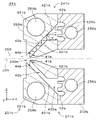
- Each light-shielding unit 241 includes an introduction reflection surface 41, a light guide path 42, and an absorption unit 43.
- the light guide path 42 is a passage (that is, a space) provided inside the light shielding unit 24.
- the introduction port 44 which is one end of the light guide path 42, is arranged in the vicinity of the 0th-order diffraction beam opening 240.
- the introduction reflection surface 41 is arranged outside the light guide path 42 in the vicinity of the introduction port 44 and the 0th-order diffraction beam opening 240.
- the introduction reflection surface 41 of the two light-shielding portions 241 is arranged on the (+ Z) side and the (-Z) side of the 0th-order diffraction beam opening 240.
- the introduction reflection surface 41 is arranged near the focusing position of the primary diffraction beam on the optical axis J36 of the primary diffraction beam from the light modulator 22.
- the introduction reflecting surface 41 reflects the primary diffraction beam and guides it to the introduction port 44 of the light guide path 42.
- the reflection direction of the primary diffraction beam by the introduction reflection surface 41 is a direction deviating from the incident direction of the primary diffraction beam with respect to the introduction reflection surface 41 and a direction away from the optical axis J35 of the zeroth diffraction beam. That is, the introduced reflective surface 41 guides the primary diffracted beam in a direction largely separated from the 0th diffractive beam.
- the primary diffraction beam reflected by the introduction reflection surface 41 is incident on the inside of the light guide path 42 from the introduction port 44.
- the light guide path 42 is a space surrounded by a light-shielding member, and extends parallel to the YZ plane (that is, a plane perpendicular to the optical axis J35 of the 0th-order diffraction beam).
- the light guide path 42 diffuses the light introduced from the introduction port 44 (hereinafter, also referred to as “introduction primary light”) along the arrow 361 in FIG. 6, and the end opposite to the introduction port 44. Lead to the end, which is the part.
- the absorption unit 43 absorbs the introduction primary light guided by the light guide path 42 at the terminal portion of the light guide path 42.
- the structure of the light-shielding portion 241 will be described.
- one light-shielding portion 241 including the introduction reflecting surface 41 located on the (-Z) side of the 0th-order diffraction beam opening 240 will be described with attention.
- the structure of the other light-shielding portion 241 is substantially point-symmetrical to the structure of the other light-shielding portion 241 with the optical axis J35 of the 0th-order diffraction beam as the center in the front view.
- the introduction reflecting surface 41 is a plane extending substantially parallel to the Z direction, and is an inclined surface toward the (+ X) side toward the (+ Y) side.
- the inclination angle of the introduction reflection surface 41 with respect to the X direction and the inclination angle with respect to the Y direction are each about 45 °.
- the introduction reflecting surface 41 is, for example, a mirror surface.
- the mirror surface means a reflection surface in which the incident primary diffraction beam is totally reflected without being substantially scattered. The same applies to the light-shielding units 24a and 24b described later.
- the primary diffraction beam is reflected in the (+ Y) direction at the substantially central portion of the introduction reflection surface 41, and heads toward the introduction port 44 of the light guide path 42.
- the primary diffraction beam reflected by the introduction reflection surface 41 is introduced into the inside of the light guide path 42 by substantially guiding the total amount of light to the introduction port 44.
- the light guide path 42 extends around the 0th-order diffraction beam opening 240 while bending so as to surround the 0th-order diffraction beam opening 240. Specifically, the light guide path 42 extends from the (-Z) side of the 0th-order diffraction beam opening 240 in the (+ Y) direction, bends at a substantially right angle, extends in the (+ Z) direction, and bends at a substantially right angle. It extends in the (-Y) direction, passes through the (+ Z) side of the 0th-order diffraction beam opening 240, and extends to the (-Y) side of the 0th-order diffraction beam opening 240. In the light-shielding unit 24, the periphery of the 0th-order diffraction beam opening 240 is surrounded by two light guide paths 42 over substantially the entire circumference.
- a first internal reflection surface 421, a second internal reflection surface 422, and a third internal reflection surface 423 are provided inside the light guide path 42.
- the first internal reflection surface 421 is arranged at a portion where the light guide path 42 bends on the (+ Y) side of the introduction reflection surface 41.
- the second internal reflection surface 422 is arranged at a portion where the light guide path 42 bends on the (+ Z) side of the first internal reflection surface 421.
- the third internal reflection surface 423 is arranged at the end of the light guide path 42 on the ( ⁇ Y) side of the second internal reflection surface 422.
- the introduction primary light reflected by the introduction reflection surface 41 and introduced into the light guide path 42 is reflected and absorbed in this order by the first internal reflection surface 421, the second internal reflection surface 422, and the third internal reflection surface 423. It is guided to the part 43.
- the first internal reflection surface 421 is a plane extending substantially parallel to the X direction, and is an inclined surface toward the (+ Z) side toward the (+ Y) side.
- the inclination angle of the first internal reflection surface 421 with respect to the Y direction and the inclination angle with respect to the Z direction are each about 45 °.
- the introduction primary light traveling in the (+ Y) direction from the introduction reflection surface 41 is directly incident on the first internal reflection surface 421 without passing through other reflection surfaces.
- the introduction primary light incident on the first internal reflection surface 421 from the introduction reflection surface 41 is reflected by the first internal reflection surface 421 in the (+ Z) direction and heads toward the second internal reflection surface 422.
- the second internal reflection surface 422 is a plane extending substantially parallel to the X direction, and is an inclined surface toward the (+ Z) side toward the (-Y) side.
- the inclination angle of the second internal reflection surface 422 with respect to the Y direction and the inclination angle with respect to the Z direction are each about 45 °.
- the introduced primary light incident on the second internal reflection surface 422 from the first internal reflection surface 421 is reflected in the ( ⁇ Y) direction by the second internal reflection surface 422 and heads toward the third internal reflection surface 423.
- the third internal reflection surface 423 is a plane extending substantially parallel to the Z direction, and is an inclined surface toward the (+ X) side toward the (-Y) side.
- the inclination angle of the third internal reflection surface 423 with respect to the X direction and the inclination angle with respect to the Y direction are each about 45 °.
- the introduced primary light incident on the third internal reflection surface 423 from the second internal reflection surface 422 is reflected in the (+ X) direction by the third internal reflection surface 423 and is the side surface of the light guide path 42 on the (+ X) side. Head to the absorption unit 43.
- the light guide path 42 is surrounded by the light shielding member, it is possible to prevent the introduction primary light directed from the introduction port 44 to the light absorbing portion 43 from leaking from the light guide path 42 to the outside of the light shielding unit 24. Will be done.
- the absorption unit 43 is a plane substantially perpendicular to the X direction, and an absorption film is provided on the surface thereof.
- the absorbent film may be a film-like or sheet-like member formed of a material that easily absorbs light, or may be a coating film formed by applying a material that easily absorbs light. ..
- the absorption unit 43 is irradiated with the introduction primary light reflected by the third internal reflection surface 423.
- the light absorbing unit 43 includes an irradiated surface to which the introduction primary light that has passed through the light guide path 42 is irradiated. In the absorption unit 43, the primary light introduced from the light guide path 42 is absorbed by the absorption film.
- FIG. 8 is an enlarged front view showing one of the above-mentioned light-shielding portions 241.
- the primary diffraction beam L36 incident on the introduction reflection surface 41 is drawn by a solid line, and the optical axis J36 of the primary diffraction beam L36 is drawn by a alternate long and short dash line.
- the introduction primary light L37 when scattering or the like does not occur on the first internal reflection surface 421, the second internal reflection surface 422, and the third internal reflection surface 423 is drawn by a two-dot chain line, and the introduction primary light is drawn.
- the optical axis J37 of the light L37 is drawn by a alternate long and short dash line.
- the introduction reflection surface 41 is arranged in the vicinity of the focusing position 360 of the primary diffraction beam L36.
- the introduction reflection surface 41 is on the optical axis J36 of the primary diffraction beam L36 and is on the front side of the focusing position 360 of the primary diffraction beam L36 (that is, the optical axis J36 of the primary diffraction beam L36). It is arranged on the optical modulator 22 side) above. Then, the primary diffraction beam L36 reflected by the introduction reflection surface 41 is focused at the focusing position 360 between the introduction reflection surface 41 and the first internal reflection surface 421.
- the focusing position 360 of the primary diffraction beam L36 is located between the introduction reflection surface 41 and the first internal reflection surface 421.
- the focusing position 360 of the primary diffraction beam L36 may be located between the introduction reflection surface 41 and the introduction port 44 of the light guide path 42 (that is, outside the light guide path 42), and may be located between the introduction port 44 and the first inside. It may be located between the reflecting surface 421 (that is, inside the light guide path 42).
- the focusing position 360 of the primary diffraction beam L36 may be located on the introduction port 44.
- the introduction primary light L37 introduced from the introduction port 44 and directed toward the first internal reflection surface 421 passes through the above-mentioned focusing position 360, and then expands the area in the cross section perpendicular to the optical axis J37 (that is, diffuses). (While) Proceed in the (+ Y) direction inside the light guide path 42. Then, after being reflected by the first internal reflection surface 421, the light is guided to the absorption unit 43 via the second internal reflection surface 422 and the third internal reflection surface 423 while diffusing in substantially the same manner. Therefore, the irradiation area of the introduced primary light L37 on the light absorbing portion 43 becomes large, and the power density of the introduced primary light L37 is reduced. As a result, it is possible to suppress the temperature rise of the absorption unit 43 (particularly, the local temperature rise in the region irradiated with the introduced primary light L37).
- the surface on which the absorption film is provided (that is, the surface on the ( ⁇ X) side) has irregularities that are convex or concave in the X direction. May be provided.
- the height of the unevenness (that is, the height in the X direction) is, for example, about several mm.
- the absorption film is provided along the unevenness.
- the introduction primary light L37 incident on the first internal reflection surface 421, the second internal reflection surface 422, and the third internal reflection surface 423 is reflected while being scattered, and the inside of the light guide path 42 is reflected toward the absorption unit 43.
- the introduction primary light L37 is further diffused.
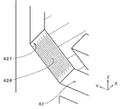
- FIG. 9 is an enlarged perspective view of the first internal reflection surface 421 provided with the fine concavo-convex 424.
- the fine unevenness 424 is a linear unevenness extending in the Y direction and the Z direction along the first internal reflection surface 421 (that is, a hairline toward the (+ Z) side toward the (+ Y) side). Is.
- the fine unevenness 424 is in the direction in which the light guide path 42 extends toward the first internal reflection surface 421 (that is, in the Y direction) and in the direction in which the light guide path 42 extends from the first internal reflection surface 421 (that is, in the Z direction). It is a linear unevenness extending along a plane parallel to both of them.
- the fine unevenness 424 is provided in both the depth direction (that is, the Y direction) to the first internal reflection surface 421 and the depth direction (that is, the Z direction) from the first internal reflection surface 421 in the light guide path 42. It is a linear unevenness extending along a plane parallel to. On the first internal reflection surface 421, a large number of the linear fine irregularities 424 are arranged in a direction substantially perpendicular to the longitudinal direction.
- the height of the fine unevenness 424 (that is, the amount of protrusion or dent from the surrounding portion) on the first internal reflection surface 421 is, for example, about several ⁇ m.
- the introduced primary light L37 (see FIG. 8) incident on the first internal reflecting surface 421 is mainly scattered in the X direction due to the linear fine unevenness 424 and reaches the first internal reflecting surface 421 of the introduced primary light L37. There is almost no scattering in the direction of returning to the incident side (that is, the (-Y) direction). Therefore, while further expanding the cross-sectional area of the introduced primary light L37 reflected by the first internal reflecting surface 421, the reflected light from the first internal reflecting surface 421 returns to the introduction port 44 and leaks from the light guide path 42. Is suppressed.
- the fine unevenness provided on the second internal reflection surface 422 extends in the Y direction and the Z direction along the second internal reflection surface 422 (that is, toward the (-Y) side toward the (+ Z) side). It is a linear unevenness. Therefore, the introduced primary light L37 incident on the second internal reflecting surface 422 is mainly scattered in the X direction and returns to the incident side of the introduced primary light L37 on the second internal reflecting surface 422 (that is, (that is,). It hardly scatters in the ⁇ Z) direction). Therefore, while further expanding the cross-sectional area of the introduced primary light L37 reflected by the second internal reflecting surface 422, the reflected light from the second internal reflecting surface 422 returns to the introduction port 44 and leaks from the light guide path 42. Is suppressed.
- the fine irregularities provided on the third internal reflection surface 423 extend in the X and Y directions along the third internal reflection surface 423 (that is, toward the ( ⁇ Y) side toward the (+ X) side). It is a linear unevenness. Therefore, the introduced primary light L37 incident on the third internal reflecting surface 423 is mainly scattered in the Z direction and returns to the incident side of the introduced primary light L37 on the third internal reflecting surface 423 (that is, (that is,). It hardly scatters in the + Y) direction). Therefore, while further expanding the cross-sectional area of the introduced primary light L37 reflected by the third internal reflecting surface 423, the reflected light from the third internal reflecting surface 423 returns to the introduction port 44 and leaks from the light guide path 42. Is suppressed.
- the first internal reflection surface 421, the second internal reflection surface 422, and the third internal reflection surface 423 are used as the scattering reflection surface, before a part of the introduced primary light L37 reaches the third internal reflection surface 423. It may be absorbed by incident on the light absorbing unit 43. Further, in the light-shielding unit 24, it is not always necessary that all of the first internal reflection surface 421, the second internal reflection surface 422, and the third internal reflection surface 423 are scattered reflection surfaces. As described above, the temperature of the absorption unit 43 rises due to the fact that one or more of the first internal reflection surface 421, the second internal reflection surface 422, and the third internal reflection surface 423 are the scattering reflection surfaces. Can be further suppressed.
- the introduction reflection surface 41 may be a scattering reflection surface. In this case, it is preferable that 86.5% or more of the light reflected by the introduction reflecting surface 41 is guided to the introduction port 44 and introduced into the light guide path 42, substantially. It is more preferable that the total amount of light is guided to the introduction port 44 and introduced into the inside of the light guide path 42.
- the entire cross section of the incident light is smaller than the first internal reflecting surface 421, and the incident light is substantially all. It is preferable that the amount of light is incident on the first internal reflection surface 421.
- the light-shielding unit 24 includes a first member 251, a second member 252, and a third member 253.
- the first member 251 is not shown. Further, in FIG. 7, the illustration of the upper end portions of the second member 252 and the third member 253 is omitted.
- the first member 251 and the third member 253 are substantially rectangular flat plate-shaped members having a through hole corresponding to the 0th-order diffraction beam opening 240 in the central portion.
- the second member 252 is a substantially rectangular frame-shaped member in which the partition wall 254 constituting the light guide path 42 is provided inside.
- the first member 251 and the second member 252 and the third member 253 have an optical axis on the (-X) side (that is, a direction in which the optical axis J35 of the 0th-order diffraction beam extends on the optical axis J35 of the 0th-order diffraction beam.
- the light-shielding unit 24 is formed by arranging them in this order from the front side in the direction and fixing them to each other.
- the first member 251 and the second member 252 and the third member 253 are light-shielding members that cannot transmit the light from the light modulator 22. By closing the gap of the second member 252 with the first member 251 and the third member 253 from both sides in the X direction, the light guide path 42 surrounded by the light-shielding member is formed.
- the first member 251 and the second member 252 and the third member 253 are made of a material that easily reflects the light from the light modulator 22 and has relatively high thermal conductivity.
- the first member 251 and the second member 252 and the third member 253 are formed of, for example, copper (Cu). Further, a thin film of gold (Au) may be provided on the above-mentioned introduction reflecting surface 41 or the like. The materials of the first member 251 and the second member 252 and the third member 253 may be changed as appropriate.
- the first member 251 is, for example, a member provided with a through hole in the central portion of a substantially flat plate-shaped copper plate extending in the Y direction and the Z direction.
- the through hole corresponds to the above-mentioned 0th-order diffraction beam opening 240, and the introduction reflection surface 41 of each light-shielding portion 241 is exposed on the (-X) side of the light-shielding unit 24.
- the main surface on the (-X) side of the first member 251 is a substantially plane extending substantially perpendicular to the X direction (that is, extending substantially perpendicular to the optical axis J35 of the 0th-order diffraction beam), and an absorption film is provided. Be done.
- the absorbent film may be a film-like or sheet-like member formed of a material that easily absorbs light, or may be a coating film formed by applying a material that easily absorbs light. ..
- the second-order diffraction beam and the third-order or higher-order diffraction beam from the light modulator 22 are incident on the (+ Z) side and the (-Z) side of the through hole. Then, it is absorbed by the above-mentioned absorption membrane.
- the periphery of the 0th-order diffraction beam opening 240 and the introduction reflection surface 41 is provided with a secondary absorption unit 255 that absorbs a higher-order diffraction beam such as a second-order diffraction beam.
- the second member 252 is, for example, one cutting block formed by cutting a substantially flat copper plate extending in the Y direction and the Z direction.
- the second member 252 is formed with a gap that serves as the light guide path 42 described above.
- the second member 252 is formed with an introduction reflection surface 41, a first internal reflection surface 421, a second internal reflection surface 422, and a third internal reflection surface 423.
- the fine unevenness 424 (see FIG. 9) of the first internal reflection surface 421 is formed by, for example, performing hairline processing on the second member 252 during cutting. As a result, the time required for manufacturing the second member 252 can be shortened as compared with the case where fine irregularities are formed on the first internal reflective surface 421 by sandblasting or the like after the cutting process of the second member 252 is completed.
- the third member 253 is, for example, a member provided with a through hole in the central portion of a substantially flat plate-shaped copper plate extending in the Y direction and the Z direction.
- the through hole corresponds to the above-mentioned 0th-order diffraction beam opening 240.
- the main surface (that is, the main surface facing the light guide path 42) on the (-X) side of the third member 253 is the absorption unit 43 provided with the absorption film as described above.
- the absorption film may also be provided on the main surface of the first member 251 on the (+ X) side (that is, the main surface facing the light guide path 42).
- the main surface on the (+ X) side of the first member 251 may be a reflective surface.
- the first member 251 and the third member 253 may also be formed by cutting like the second member 252.
- FIG. 10 is a front view showing the third member 253.
- the above-mentioned light guide path 42 is also shown by a two-dot chain line.
- a cooling flow path 256 is provided inside the third member 253.
- the cooling flow path 256 is arranged in the vicinity of the light absorbing section 43 (that is, the main surface on the (-X) side of the third member 253).
- a refrigerant such as water flows inside the cooling flow path 256.
- the vicinity of the absorption unit 43 described above means a range in which the absorption unit 43 can be effectively cooled by the refrigerant flowing through the cooling flow path 256.
- the cooling flow path 256 overlaps with the light guide path 42 of each light-shielding portion 241 in the front view.
- the vicinity of the light guide path 42 described above means a range in which the light guide path 42 can be effectively cooled by the refrigerant flowing through the cooling flow path 256.
- a temperature sensor may be arranged in the vicinity of the cooling flow path 256, and the temperature of the light absorption unit 43 and the light guide path 42 may be measured. Thereby, the abnormal temperature rise of the light shielding unit 24 can be easily detected.
- the optical device 12 includes an illumination optical system 21, an optical modulator 22, and a projection optical system 23.
- the illumination optical system 21 shapes the laser beam emitted from the laser light source 11 into a predetermined shape.
- the light modulator 22 modulates the laser beam shaped by the illumination optical system 21 into the modulation beam L33.
- the projection optical system 23 guides the modulated beam L33 to the object (in the above example, the scanning unit 13).
- the projection optical system 23 includes a light-shielding unit 24 that passes the 0th-order diffraction beam L35 from the light modulator 22 and blocks the 1st-order diffraction beam L36.
- the light-shielding unit 24 includes a 0th-order diffraction beam opening 240, an introduction reflection surface 41, a light guide path 42, and an absorption unit 43.
- the 0th-order diffraction beam opening 240 is located near the focusing position of the 0th-order diffraction beam L35 on the optical axis J35 of the 0th-order diffraction beam L35, and passes through the 0th-order diffraction beam L35.
- the introduction reflection surface 41 is located near the focusing position 360 of the primary diffraction beam L36 on the optical axis J36 of the primary diffraction beam L36 and near the 0th-order diffraction beam opening 240.
- the introduction reflecting surface 41 reflects the primary diffraction beam L36 in a direction deviating from the incident direction of the primary diffraction beam L36 and in a direction away from the optical axis J35 of the 0th-order diffraction beam L35.
- the light guide path 42 has an introduction port 44 into which the light from the introduction reflection surface 41 is incident, and guides the light introduced from the introduction port 44 (that is, the introduction primary light).
- the light guide path 42 is surrounded by a light-shielding member.
- the absorption unit 43 absorbs the light guided while being diffused by the light guide path 42.
- the leakage of light from the light-shielding unit 24 to the outside can be suppressed by guiding the introduced primary light to the light-absorbing unit 43 by the light guide path 42 surrounded by the light-shielding member. Further, by guiding the introduced primary light to the light absorption unit 43 while diffusing it in the light guide path 42, the light absorption unit 43 is irradiated even when the power density of the laser light emitted from the laser light source 11 is high. The power density of the introduction primary light can be lowered.
- the absorbance required for the absorption unit 43 can be reduced, the degree of freedom in selecting the absorption film used in the absorption unit 43 can be improved. Therefore, by using a relatively inexpensive and long-life absorption film instead of an expensive and short-life absorption film having a very high absorbance, it is possible to reduce the manufacturing cost and extend the life of the light-shielding unit 24. ..
- the introduction reflecting surface 41 is preferably a mirror surface. This prevents scattering of the primary diffraction beam L36 on the introduction reflection surface 41, so that the primary diffraction beam L36 is on the front side of the light guide path 42 (that is, on the light modulator 22 side along the optical axis J36 of the primary diffraction beam L36). It is possible to prevent or suppress the temperature rise. Further, substantially the total amount of light of the primary diffraction beam L36 incident on the introduction reflection surface 41 can be introduced into the inside of the light guide path 42. Therefore, it is possible to prevent or suppress the temperature rise of the optical elements and the like around the light-shielding unit 24.
- the light guide path 42 is internally provided with a scattering reflection surface (for example, a first internal reflection surface 421) that reflects and guides the light from the introduction reflection surface 41 while scattering it. This makes it possible to promote the diffusion of the introduced primary light inside the light guide path 42.
- a scattering reflection surface for example, a first internal reflection surface 421
- the scattering reflection surface (for example, the first internal reflection surface 421) is preferably along a plane parallel to both the depth direction to the scattering reflection surface and the depth direction from the scattering reflection surface in the light guide path 42. It has a linear fine unevenness 424 that extends.
- the introduction primary light can be scattered on the scattering reflection surface while suppressing the introduction primary light reflected by the scattering reflection surface from returning to the incident direction.
- the diffusion of the introduced primary light inside the light guide path 42 can be suitably promoted.
- the introduction reflection surface 41 is arranged on the optical axis J36 of the primary diffraction beam L36 in front of the focusing position 360 of the primary diffraction beam L36.
- the power density of the primary diffraction beam L36 on the introduction reflection surface 41 can be reduced as compared with the case where the introduction reflection surface 41 is arranged at the focusing position 360.
- a primary diffraction beam is provided between the reflection surface (that is, the first internal reflection surface 421) on which the light from the introduction reflection surface 41 is directly incident and the introduction reflection surface 41.
- L36 is focused.
- the power density of the introduced primary light on the first internal reflection surface 421 can be reduced as compared with the case where the focusing position 360 is located on the first internal reflection surface 421.
- the absorption unit 43 is located.
- the degree of diffusion of the introduced primary light at the time of arrival can be increased.
- the power density of the introduced primary light irradiated to the light absorbing unit 43 can be lowered, and the temperature rise of the light shielding unit 24 can be suppressed.
- the cross-sectional area of the light passing through the introduction port 44 can be reduced. As a result, it is possible to suppress the increase in size of the introduction port 44 and the light shielding unit 24.
- the introduction reflection surface 41 may be arranged at the focusing position 360 of the primary diffraction beam L36. In this case, the area of the introduced reflective surface 41 can be reduced. Further, since the gap between the primary diffraction beam L36 and the 0th-order diffraction beam L35 becomes large, the primary diffraction beam L36 can be easily separated from the 0th-order diffraction beam L35.
- the introduction reflection surface 41 sets the focusing position 360 on the optical axis J36 of the primary diffraction beam L36 behind the focusing position 360 of the primary diffraction beam L36 (that is, on the optical axis J36 of the primary diffraction beam L36). It may be sandwiched and arranged on the opposite side of the optical modulator 22). In this case, the power density of the primary diffraction beam L36 on the introduction reflection surface 41 can be reduced. As a result, it is possible to suppress the temperature rise and damage of the introduced reflective surface 41. Further, it is possible to reliably prevent the introduction primary light introduced from the introduction reflection surface 41 into the light guide path 42 from being focused on any of the reflection surfaces in the light guide path 42. Therefore, it is possible to suppress the temperature rise and damage of each reflecting surface in the light guide path 42.
- the absorption unit 43 includes an uneven surface on which an absorption film is provided on the surface. As a result, the irradiation area of the introduced primary light on the light absorbing unit 43 can be increased, and the power density of the introduced primary light irradiated to the light absorbing unit 43 can be lowered. As a result, the temperature rise of the light-shielding unit 24 can be further suppressed.
- the light-shielding unit 24 is further provided with a cooling flow path 256 that is arranged in the vicinity of the light-absorbing unit 43 and through which the refrigerant flows.
- the cooling flow path 256 through which the refrigerant flows is arranged also in the vicinity of the light guide path 42. As a result, the light guide path 42 can also be cooled, and the temperature rise of the light shielding unit 24 can be further suppressed.
- the light modulator 22 is placed on the outer surface extending in the direction perpendicular to the optical axis J35 of the 0th-order diffraction beam L35 around the 0th-order diffraction beam opening 240 and the introduction reflection surface 41. It is preferable to provide a secondary absorption unit 255 that absorbs the secondary diffraction beam. As a result, it is possible to shield the non-zero-order diffracted beam of the second order or higher while suppressing the increase in size of the light-shielding unit 24.
- the light guide path 42 extends parallel to the plane perpendicular to the optical axis J35 of the 0th-order diffraction beam L35. This makes it possible to reduce the size of the light-shielding unit 24 in the direction in which the optical axis J35 extends.
- the light guide path 42 extends while bending around the 0th-order diffraction beam opening 240 and surrounds the 0th-order diffraction beam opening 240.
- the light-shielding unit 24 can be miniaturized in front view (that is, when viewed along the optical axis J35 of the 0th-order diffraction beam L35).
- the introduction reflective surface 41 and the light guide path 42 are one cutting block formed by cutting (in the above example, the second member 252). It is preferable to be provided in. As a result, the light-shielding unit 24 can be manufactured while maintaining the relative position between the introduction reflection surface 41 and the light guide path 42 with high accuracy.
- the above-mentioned three-dimensional modeling apparatus 1 includes the above-mentioned optical apparatus 12, a laser light source 11, and a scanning unit 13.
- the laser light source 11 emits the laser beam L31 to the optical device 12.
- the scanning unit 13 is the object to which the modulated beam L33 from the optical device 12 is irradiated, and scans the modulated beam L33 on the modeling material 91.
- the modulation beam L33 irradiated to the object (that is, the scanning unit 13) while suppressing the temperature rise of the optical element.
- the power density can be suitably increased.
- the power density of the modulated beam L33 irradiated on the modeling material 91 can also be suitably increased.
- the modeling speed of the modeled object in the three-dimensional modeling device 1 can be increased, and the productivity can be improved.
- the optical device according to the second embodiment has the same structure as the optical device 12 shown in FIGS. 1 to 3 except that a light-shielding unit 24a having a structure different from that of the above-mentioned light-shielding unit 24 is provided.
- a light-shielding unit 24a having a structure different from that of the above-mentioned light-shielding unit 24 is provided.
- the same components as those of the above-mentioned optical device 12 are designated by the same reference numerals.
- FIGS. 11 and 12 are diagrams for wetting the structure of the projection optical system 23a provided with the light-shielding unit 24a, and correspond to FIGS. 2 and 3 described above. That is, in FIG. 11, the direction perpendicular to the paper surface corresponds to the short axis direction of the modulated beam L33, and the vertical direction in the figure corresponds to the long axis direction of the modulated beam L33. Further, in FIG. 12, the direction perpendicular to the paper surface corresponds to the long axis direction of the modulation beam L33, and the vertical direction in the figure corresponds to the short axis direction of the modulation beam L33.
- the light modulator 22 is, for example, a two-dimensional spatial light modulation element.
- PLV Planar Light Valve
- LPLV Liner Planar Light Valve
- DMD Digital Micromirror Device
- the shading unit 24a is arranged between the first lens 231 and the second lens 232 on the optical path of the modulated beam L33.
- the light-shielding unit 24a passes the 0th-order diffraction beam L35 from the light modulator 22 and blocks the 1st-order diffraction beam L36.
- the light-shielding unit 24a is arranged near the focusing position of the 0th-order diffraction beam L35, and blocks the four primary diffraction beams L36 that focus on both sides in the major axis direction and both sides in the minor axis direction of the 0th-order diffraction beam L35.
- the primary diffraction beam L36 blocked by the light-shielding unit 24a is focused in both the major axis direction and the minor axis direction.
- the light-shielding unit 24a also blocks a second-order or higher non-zero-order diffraction beam (not shown) from the light modulator 22.
- FIG. 13 is a perspective view showing the appearance of the light shielding unit 24a.
- FIG. 14 is a perspective view showing the inside of the light shielding unit 24a.
- FIG. 15 is a vertical cross-sectional view of the light-shielding unit 24a in a cross section of the 0th-order diffracted beam from the light modulator 22 passing through the optical axis J35.
- the light-shielding unit 24a includes a 0th-order diffraction beam opening 240a through which the 0th-order diffraction beam passes.
- the 0th-order diffraction beam aperture 240a is located near the focusing position of the 0th-order diffraction beam on the optical axis J35 of the 0th-order diffraction beam, similarly to the 0th-order diffraction beam aperture 240 (see FIG. 4) described above.
- the light-shielding unit 24a includes a first member 251a and a second member 252a. In FIG. 14, the first member 251a is not shown.
- the first member 251a and the second member 252a are substantially rectangular flat plate-shaped members provided with a substantially circular through hole corresponding to the 0th-order diffraction beam opening 240a in the central portion.
- the first member 251a and the second member 252a are on the (-X) side (that is, the front side in the optical axis direction in which the optical axis J35 of the 0th-order diffraction beam extends) on the optical axis J35 of the 0th-order diffraction beam.
- the light-shielding units 24a are formed by arranging them in this order and fixing them to each other.
- the first member 251a and the second member 252a are light-shielding members that cannot transmit the light from the light modulator 22.
- the materials of the first member 251a and the second member 252a are, for example, the same as the first member 251, the second member 252, and the third member 253 of the light-shielding unit 24 described above.
- the second member 252a is, for example, one cutting block formed by cutting.
- the first member 251a may also be formed by cutting.
- an annular inward protrusion 257a and an annular recess 258a are formed on the main surface of the second member 252a on the (-X) side (that is, the light modulator 22 side in the direction in which the optical axis J35 of the 0th-order diffraction beam extends). It is provided.
- the internal protrusion 257a is provided along the peripheral edge of the through hole (that is, the through hole corresponding to the 0th-order diffraction beam opening 240a) in the central portion of the second member 252.
- the internal protrusion 257a projects from the main surface of the second member 252 on the (-X) side to the (-X) side.
- the annular recess 258a is continuously radially outward from the outer peripheral edge of the inner protrusion 257a in the radial direction (hereinafter, also simply referred to as “diameter direction”) about the optical axis J35 of the 0th-order diffractive beam. It is an annular recess that expands.
- the annular recess 258a is recessed toward the (+ X) side with respect to the inner protrusion 257a and the portion radially outside the annular recess 258a.
- the inner protrusion 257a and the annular recess 258a are substantially annular in a front view, arranged concentrically around the optical axis J35 of the 0th-order diffraction beam.
- the inner protrusion 257a has a shape in which a substantially columnar through hole is provided in the central portion of a substantially truncated cone centered on the optical axis J35.
- the radial outer side surface of the inner protrusion 257a (that is, the inner peripheral surface which is the radial inner side surface of the annular recess 258a) is the introduction reflection surface 41a corresponding to the introduction reflection surface 41 described above.
- the introduction reflection surface 41a is located in the vicinity of the 0th-order diffractive beam opening 240a and surrounds the 0th-order diffractive beam opening 240a.
- the introduction reflecting surface 41a is a substantially annular inclined surface (that is, a surface having a substantially truncated cone side surface shape) centered on the optical axis J35.
- the introduction reflecting surface 41a tends toward the (+ X) side as it goes outward in the radial direction. In other words, the introduction reflecting surface 41a separates from the optical axis J35 from the front side to the back side in the direction in which the optical axis J35 of the 0th-order diffracted beam extends (that is, the optical axis direction).
- the introduction reflecting surface 41a is, for example, a mirror surface.
- the introduction reflection surface 41a may be a scattering reflection surface.
- the annular recess 258a is closed from the (-X) side by the first member 251a having a through hole in the central portion, so that the annular recess 258a becomes a light guide path 42a corresponding to the above-mentioned light guide path 42.
- the light guide path 42a is a substantially annular space that radially extends outward in the radial direction about the optical axis J35 of the 0th-order diffracted beam, and is surrounded by a light-shielding member.
- the through hole of the first member 251 is a substantially circular shape having a diameter larger than that of the internal protrusion 257a in a front view, and exposes the introduction reflecting surface 41a on the (-X) side of the light shielding unit 24a.
- the introduction port 44a of the light guide path 42a is a substantially cylindrical region extending in the X direction between the outer peripheral edge of the through hole of the first member 251a and the surface of the annular recess 258a on the (+ X) side.
- the introduction port 44a faces the introduction reflection surface 41a in the radial direction.
- the outer peripheral surface which is the radial outer side surface of the annular recess 258a, is the internal reflection surface 421a corresponding to the above-mentioned first internal reflection surface 421, second internal reflection surface 422, and third internal reflection surface 423.
- the internal reflection surface 421a is a substantially annular inclined surface centered on the optical axis J35.
- the internal reflecting surface 421a has a substantially truncated cone side surface shape toward the (-X) side as it goes outward in the radial direction.
- the internal reflection surface 421a faces the introduction port 44a and the introduction reflection surface 41a in the radial direction.
- the height of the internal reflection surface 421a in the X direction is substantially the same as the height of the introduction reflection surface 41a in the X direction.
- the internal reflection surface 421a is a scattering reflection surface provided with fine irregularities in substantially the same manner as the first internal reflection surface 421 and the like.
- the fine unevenness is, for example, a linear unevenness (that is, a hairline) extending in the radial direction along the internal reflection surface 421a.
- the linear unevenness is parallel to both the depth direction (that is, the radial direction) to the internal reflection surface 421a and the depth direction (that is, the X direction) from the internal reflection surface 421a in the light guide path 42a. Extends along a straight surface.
- the portion facing the annular recess 258a of the second member 252a in the X direction is the absorption portion 43a corresponding to the above-mentioned absorption portion 43.
- the absorption unit 43a is a plane substantially perpendicular to the X direction, and an absorption film similar to the absorption unit 43 is provided on the surface thereof.
- the light absorbing portion 43a is an uneven surface on which a light absorbing film is provided on the surface.
- the unevenness provided on the light absorbing portion 43a is, for example, concentric circles centered on the optical axis J35, and the height of the unevenness (that is, the height in the X direction) is, for example, about several mm.
- the absorption unit 43a may be a smooth surface having substantially no unevenness.
- the main surface on the (-X) side of the first member 251a (that is, the main surface on the (-X) side of the light-shielding unit 24a) is a substantially flat surface extending substantially perpendicular to the X direction, and the above-mentioned secondary absorption unit 255.
- the secondary absorption unit 255a corresponding to the above is provided.
- the secondary absorption unit 255a absorbs a higher-order diffraction beam such as a second-order diffraction beam around the 0th-order diffraction beam opening 240a and the introduction reflection surface 41a.
- the above four primary diffraction beams from the light modulator 22 are incident on the introduction reflection surface 41a.
- the four primary diffraction beams are incident on the (+ Y) side, the ( ⁇ Y) side, the (+ Z) side, and the (—Z) side of the 0th order diffraction beam aperture 240a on the introduction reflection surface 41a.
- the introduction reflection surface 41a is arranged on the optical axis J36 of the four primary diffraction beams in the vicinity of the focusing position of the four primary diffraction beams.
- the introduction reflecting surface 41a reflects each of the four primary diffraction beams and guides them to the introduction port 44a of the light guide path 42a. Specifically, the primary diffraction beam incident on the introduction reflection surface 41a on the (+ Y) side of the 0th-order diffraction beam opening 240a is reflected in the (+ Y) direction and introduced into the light guide path 42a. The primary diffraction beam incident on the introduction reflection surface 41a on the (—Y) side of the 0th order diffraction beam opening 240a is reflected in the (—Y) direction and introduced into the light guide path 42a.
- the primary diffraction beam incident on the introduction reflection surface 41a on the (+ Z) side of the 0th-order diffraction beam opening 240a is reflected in the (+ Z) direction and introduced into the light guide path 42a.
- the primary diffraction beam incident on the introduction reflection surface 41a on the (-Z) side of the 0th-order diffraction beam opening 240a is reflected in the (-Z) direction and introduced into the light guide path 42a.
- the reflection direction of each primary diffraction beam by the introduction reflection surface 41a is a direction deviating from the incident direction of each primary diffraction beam with respect to the introduction reflection surface 41a and a direction away from the optical axis J35 of the zeroth diffraction beam. .. That is, the introduction reflecting surface 41a guides each of the first-order diffracted beams in a direction largely separated from the zero-order diffracted beam.
- the light guide path 42a is a space surrounded by a light-shielding member, and extends radially parallel to the YZ plane (that is, a plane perpendicular to the optical axis J35 of the 0th-order diffraction beam).
- the light guide path 42a diffuses the four introduction primary lights introduced from the introduction port 44a along the arrow 362 in FIG. 15, and the end portion opposite to the introduction port 44a (that is, the outside in the radial direction). It leads to the internal reflection surface 421a located at the end portion).
- Each of the four introduction primary lights incident on the internal reflection surface 421a is reflected in the (-X) direction and is applied to the light absorption unit 43a, which is the irradiated surface provided at the end of the light guide path 42a.
- the absorption unit 43a absorbs the four introduction primary lights guided by the light guide path 42a.
- the introduced primary light is scattered in the circumferential direction (hereinafter, also simply referred to as “circumferential direction”) about the optical axis J35 due to the linear unevenness extending along the above-mentioned radial direction. It is reflected while.
- the cross-sectional area (that is, the irradiation area) of the introduced primary light irradiated to the light absorbing portion 43a is expanded. Since the introduced primary light is hardly scattered in the radial direction on the internal reflecting surface 421a, it is suppressed that the reflected light from the internal reflecting surface 421a returns to the introduction port 44a and leaks from the light guide path 42a. Further, as shown in FIG.
- the surface of the light absorbing portion 43a is an uneven surface composed of an inclined surface inclined in the X direction with respect to the Z direction, among the introduced primary light incident on the light absorbing portion 43a, It is possible to suppress that the light that cannot be completely absorbed by the absorption unit 43a and is reflected is reflected toward the direction of the internal reflection surface 421a (that is, the (+ X) direction). That is, by making the surface of the absorption unit 43a an inclined surface inclined with respect to the X direction, the light incident on the inclined surface of the absorption unit 43a from the internal reflection surface 421a and reflected is directed in the (+ Z) direction or (-). It can be directed in the Z) direction and incident on another part of the absorption unit 43a. As a result, more light can be absorbed by the light absorbing section 43a, and the amount of light leaking to the outside from the light guide path 42a can be further reduced.
- each light-shielding unit 241a includes an introduction reflection surface 41a, a light guide path 42a, an internal reflection surface 421a, and an absorption unit 43a.
- each light-shielding portion 241a are a part of the inner peripheral surface of the annular recess 258a, a part of the annular recess 258a, and a part of the outer peripheral surface of the annular recess 258a. be.
- FIG. 16 is an enlarged cross-sectional view showing one light-shielding portion 241a.
- the primary diffraction beam L36 incident on the introduction reflection surface 41a is drawn by a solid line
- the optical axis J36 of the primary diffraction beam L36 is drawn by a alternate long and short dash line.
- the introduction primary light L37 when scattering or the like does not occur on the internal reflection surface 421a is drawn by a solid line
- the optical axis J37 of the introduction primary light L37 is drawn by a alternate long and short dash line.
- the introduction reflection surface 41a is arranged in the vicinity of the focusing position 360 of the primary diffraction beam L36.
- the introduction reflection surface 41a is on the optical axis J36 of the primary diffraction beam L36 and behind the focusing position 360 of the primary diffraction beam L36 (that is, the optical axis J36 of the primary diffraction beam L36). (On the side opposite to the optical modulator 22 side) with the focusing position 360 in between.
- the focusing position 360 of the primary diffraction beam L36 is located between the introduction reflection surface 41a and the light modulator 22 (see FIGS. 11 and 12).
- the primary diffraction beam L36 directed from the light modulator 22 toward the introduction reflection surface 41a expands (that is, diffuses) the area in the cross section perpendicular to the optical axis J36 and introduces reflection. It is incident on the surface 41a.
- the introduction primary light L37 reflected by the introduction reflection surface 41a and introduced into the light guide path 42a advances inside the light guide path 42a to the internal reflection surface 421a while being diffused in substantially the same manner.
- the introduced primary light l37 is guided to the light absorbing portion 43a while being diffused in substantially the same manner after being reflected by the internal reflecting surface 421a.
- the irradiation area of the introduced primary light L37 on the light absorbing portion 43a becomes large, and the power density of the introduced primary light L37 is reduced. As a result, it is possible to suppress the temperature rise of the absorption unit 43a (particularly, the local temperature rise in the region irradiated with the introduced primary light L37).
- a cooling flow path 256a is provided on the (-X) side of the absorption unit 43a.
- the cooling flow path 256a is arranged in the vicinity of the light absorbing portion 43a (that is, the main surface on the (+ X) side of the first member 251a).
- the cooling flow path 256a has, for example, a rectangular frame shape that substantially overlaps with the annular recess 258a in the front view.
- a refrigerant such as water flows inside the cooling flow path 256a. As a result, the temperature rise of the absorption unit 43a can be further suppressed.
- a cooling flow path 259a is provided on the (+ X) side of the light guide path 42a.
- the cooling flow path 259a is arranged in the vicinity of the light guide path 42a.
- the cooling flow path 259a has, for example, a rectangular frame shape that substantially overlaps with the annular recess 258a in the front view.
- a refrigerant such as water flows inside the cooling flow path 259a.
- a temperature sensor may be arranged in the vicinity of the cooling flow paths 256a and 259a, and the temperatures of the light absorption unit 43a and the light guide path 42a may be measured. Thereby, the abnormal temperature rise of the light shielding unit 24a can be easily detected.
- the projection optical system 23a passes the 0th-order diffraction beam L35 from the light modulator 22 as in the first embodiment.
- a light shielding unit 24a that blocks the primary diffraction beam L36 is provided.
- the light-shielding unit 24a includes a 0th-order diffraction beam opening 240a, an introduction reflection surface 41a, a light guide path 42a, and an absorption unit 43a.
- the 0th-order diffraction beam opening 240a is located near the focusing position of the 0th-order diffraction beam L35 on the optical axis J35 of the 0th-order diffraction beam L35, and passes through the 0th-order diffraction beam L35.
- the introduction reflection surface 41a is located near the focusing position 360 of the primary diffraction beam L36 on the optical axis J36 of the primary diffraction beam L36 and near the 0th-order diffraction beam opening 240a.
- the introduction reflecting surface 41a reflects the primary diffraction beam L36 in a direction deviating from the incident direction of the primary diffraction beam L36 and in a direction away from the optical axis J35 of the 0th-order diffraction beam L35.
- the light guide path 42a has an introduction port 44a into which the light from the introduction reflection surface 41a is incident, and guides the light introduced from the introduction port 44a (that is, the introduction primary light).
- the light guide path 42a is surrounded by a light-shielding member.
- the absorption unit 43a absorbs the light guided while being diffused by the light guide path 42a.
- the light-shielding unit 24a can suppress the leakage of light from the light-shielding unit 24a to the outside and can also suppress the temperature rise of the light-shielding unit 24a, substantially like the above-mentioned light-shielding unit 24. Further, since the absorption film having a long life can be used at a relatively low cost, the manufacturing cost of the light-shielding unit 24a can be reduced and the life can be extended.
- the introduction reflecting surface 41a is preferably a mirror surface. Further, it is preferable that the light guide path 42a is provided with a scattered reflection surface (that is, an internal reflection surface 421a) that reflects and guides the light from the introduction reflection surface 41a while scattering it. As a result, it is possible to prevent the primary diffraction beam L36 from being scattered on the introduction reflection surface 41a and to introduce substantially the entire amount of light of the primary diffraction beam L36 incident on the introduction reflection surface 41a into the light guide path 42a. can. In addition, it is possible to promote the diffusion of the introduced primary light inside the light guide path 42a.
- a scattered reflection surface that is, an internal reflection surface 421a
- the internal reflection surface 421a is preferably parallel to both the depth direction (that is, the radial direction) to the internal reflection surface 421a and the depth direction (that is, the X direction) from the internal reflection surface 421a in the light guide path 42a. It has linear fine irregularities extending along the surface. As a result, the introduced primary light can be scattered while suppressing the introduction primary light incident on the internal reflection surface 421a from returning to the incident direction (that is, inward in the radial direction). As a result, the diffusion of the introduced primary light inside the light guide path 42a can be suitably promoted.
- the introduction reflection surface 41a is arranged on the optical axis J36 of the primary diffraction beam L36 behind the focusing position 360 of the primary diffraction beam L36.
- the power density of the primary diffraction beam L36 on the introduced reflection surface 41a can be reduced.
- the introduction reflection surface 41a may be arranged on the optical axis J36 of the primary diffraction beam L36 in front of the focusing position 360 of the primary diffraction beam L36.
- the power density of the primary diffraction beam L36 on the introduced reflection surface 41a can be reduced in the same manner as described above. As a result, it is possible to suppress the temperature rise and damage of the introduced reflective surface 41a.
- the primary diffraction is performed between the reflection surface (that is, the internal reflection surface 421a) on which the introduction primary light directly incident from the introduction reflection surface 41a is directly incident and the introduction reflection surface 41a. It is preferable that the beam L36 is focused. As a result, the power density of the primary diffraction beam L36 on the internal reflection surface 421a can be reduced. As a result, it is possible to suppress the temperature rise and damage of the internal reflection surface 421a.
- the introduction reflection surface 41a may be arranged at the focusing position 360 of the primary diffraction beam L36. In this case, the area of the introduced reflective surface 41a can be reduced. Further, since the gap between the primary diffraction beam L36 and the 0th-order diffraction beam L35 becomes large, the primary diffraction beam L36 can be easily separated from the 0th-order diffraction beam L35.
- the light absorbing portion 43a is provided with an uneven surface on which the light absorbing film is provided on the surface. As a result, the irradiation area of the introduced primary light on the light absorbing unit 43a can be increased, and the power density of the introduced primary light irradiated to the light absorbing unit 43a can be lowered. As a result, the temperature rise of the light-shielding unit 24a can be further suppressed.
- the light-shielding unit 24a is further provided with a cooling flow path 256a arranged in the vicinity of the light-absorbing portion 43a and through which the refrigerant flows.
- a cooling flow path 259a through which the refrigerant flows is arranged also in the vicinity of the light guide path 42a. As a result, the light guide path 42a can also be cooled, and the temperature rise of the light shielding unit 24a can be further suppressed.
- the light-shielding unit 24a from the light modulator 22 on the outer surface extending in the direction perpendicular to the optical axis J35 of the 0th-order diffraction beam L35 around the 0th-order diffraction beam opening 240a and the introduction reflection surface 41a. It is preferable to provide a secondary absorption unit 255a that absorbs the secondary diffraction beam. As a result, it is possible to shield the non-zero-order diffracted beam of the second order or higher while suppressing the increase in size of the light-shielding unit 24a.
- the light guide path 42a extends parallel to the plane perpendicular to the optical axis J35 of the 0th-order diffraction beam L35. This makes it possible to reduce the size of the light-shielding unit 24a in the direction in which the optical axis J35 extends.
- the introduction reflective surface 41a and the light guide path 42a are one cutting block formed by cutting (in the above example, the second member 252a). It is preferable to be provided in. As a result, the light-shielding unit 24a can be manufactured while maintaining the relative position between the introduction reflection surface 41a and the light guide path 42a with high accuracy.
- the introduction reflecting surface 41a surrounds the periphery of the 0th-order diffraction beam opening 240a, and from the optical axis J35 of the 0th-order diffraction beam L35 from the front side to the back side in the optical axis direction of the 0th-order diffraction beam L35. It is preferably part of a distant circumferentially inclined surface. Further, the light guide path 42a is preferably a part of an annular space that radiates outward from the circumferential inclined surface. As a result, even when the number of primary diffraction beams L36 that are shielded by the light-shielding unit 24a is large, it can be easily dealt with without changing the structure of the light-shielding unit 24a.
- the power density of the modulated beam L33 irradiated to the modeling material 91 can be suitably increased in the same manner as described above.
- the modeling speed of the modeled object in the three-dimensional modeling device 1 can be increased, and the productivity can be improved.
- a light-shielding unit 24b having a structure different from that of the above-mentioned light-shielding units 24 and 24a is provided.
- a two-dimensional spatial light modulation element for example, LPLV
- the optical elements of the illumination optical system 21 and the projection optical system 23 are changed.
- the 0th-order diffractive beam, the 1st-order diffractive beam, and the second-order or higher non-0th-order diffractive beam incident on the light-shielding unit 24b are focused in only one of the major axis direction and the minor axis direction.
- FIG. 17 is a perspective view showing the appearance of the light shielding unit 24b.
- FIG. 18 is a perspective view showing the inside of the light shielding unit 24b. In FIG. 18, the upper part of the shading unit 24b is not shown.
- FIG. 19 is a cross-sectional view of the light shielding unit 24b.
- the light-shielding unit 24b is arranged near the focusing position of the 0th-order diffraction beam b from the light modulator 22 (see FIG. 1), includes a 0th-order diffraction beam opening 240b through which the 0th-order diffraction beam passes, and a first-order diffraction beam. Block.
- the 0th-order diffractive beam and the 1st-order diffractive beam incident on the light-shielding unit 24b are focused only in the minor axis direction and not in the major axis direction (that is, the vertical direction in FIG. 17).
- the 0th-order diffraction beam and the 1st-order diffraction beam are planar beams extending in the long axis direction.
- the 0th-order diffraction beam opening 240b has a slit shape extending in the major axis direction (that is, the Z direction).
- the light-shielding unit 24b blocks two primary diffraction beams focused on both sides (that is, the (+ Y) side and the ( ⁇ Y) side) of the 0th-order diffraction beam in the minor axis direction.
- the light-shielding unit 24b includes a first member 251b and a second member 252b.
- the first member 251b and the second member 252b are substantially rectangular parallelepiped members provided with a slit (that is, a long through hole or groove in the vertical direction) corresponding to the 0th-order diffraction beam opening 240b in the central portion.
- the first member 251b and the second member 252b are on the (-X) side (that is, the front side in the optical axis direction in which the optical axis J35 of the 0th-order diffraction beam extends) on the optical axis J35 of the 0th-order diffraction beam.
- the light-shielding units 24b are formed by arranging them in this order and fixing them to each other.
- the first member 251b and the second member 252b are light-shielding members that cannot transmit the light from the light modulator 22.
- the materials of the first member 251b and the second member 252b are, for example, the same as the first member 251, the second member 252, and the third member 253 of the light-shielding unit 24 described above.
- the first member 251b is formed by connecting two first blocks 261b arranged adjacently in the Y direction.
- Each first block 261b is a light-shielding portion 241b including an introduction reflection surface 41b and a light guide path 42b, as will be described later.
- Each of the two first blocks 261b is, for example, one cutting block formed by cutting.
- each first block 261b may have a plurality of cutting blocks fixed to each other.
- the slit-shaped space extending in the Z direction between the two first blocks 261b separated in the Y direction corresponds to the 0th-order diffraction beam opening 240b.
- each first block 261b is provided with a light guide path 42b toward a direction away from the 0th-order diffraction beam opening 240b (that is, a direction away from the optical axis J35 of the 0th-order diffraction beam) toward the (+ X) direction. ..
- the light guide path 42b is a slit-shaped space extending in the direction inclined and the Z direction with respect to the optical axis J35 of the 0th-order diffracted beam.
- the side surfaces on both sides of the light guide path 42b are a pair of reflective surfaces 421b parallel to each other.
- Each reflecting surface 421b is, for example, a mirror surface.
- the primary diffractive beam from the light modulator 22 is the end portion (that is, -X) side of the (+ X) side reflecting surface 421b of the pair of reflecting surfaces 421b.
- the end of the 0th-order diffractive beam near the optical axis J35) is reflected at the end, and is guided to the light guide path 42b. That is, the end portion is an introduction reflection surface 41b that guides the primary diffraction beam to the light guide path 42b. Further, the space in the vicinity of the introduction reflection surface 41b of the light guide path 42b is the introduction port 44b.
- the introduction primary light introduced from the introduction reflection surface 41b into the light guide path 42b is repeatedly reflected between the pair of reflection surfaces 421b along the arrow 363, and is guided while reciprocating between the pair of reflection surfaces 421b. It is guided in the optical path 42b in the (+ X) direction and in the direction away from the optical axis J35 of the 0th-order diffracted beam. That is, of the pair of reflective surfaces 421b, the portion other than the introduced reflective surface 41b (that is, the end portion of the reflective surface 421b on the (+ X) side on the (-X) side) is inside the light guide path 42b. It is a reflective surface.
- the introduction primary light is guided to the terminal portion 425b (that is, the end portion on the (+ X) side) of the light guide path 42b while diffusing in the same manner as described above.
- the distance between the pair of reflecting surfaces 421b in a plan view gradually increases toward the (+ X) side.
- the introduced primary light is further diffused by being repeatedly reflected between the pair of reflecting surfaces 421b at the terminal portion 425b of the light guide path 42b.
- the introduced primary light that has passed through the terminal portion 425b of the light guide path 42b is absorbed by the light absorbing portion 43b provided in the region facing the terminal portion 425b in the X direction on the main surface of the second member 252b on the (-X) side.
- the irradiation area of the introduced primary light on the absorption unit 43b becomes large, and the power density of the introduced primary light is reduced. As a result, it is possible to suppress the temperature rise of the absorption unit 43b (particularly, the local temperature rise in the region irradiated with the introduction primary light).
- the pair of reflective surfaces 421b may be provided with fine irregularities at the terminal portion 425b to form a scattered reflective surface.
- the fine irregularities extend in the X direction along, for example, each reflecting surface 421b (that is, in both the depth direction to each reflecting surface 421b and the depth direction from each reflecting surface 421b at the terminal portion 425b of the light guide path 42b. It is a linear unevenness (extending along parallel planes). As a result, it is suppressed that the reflected light at the terminal portion 425b of each reflecting surface 421b returns to the introduction port 44b and leaks from the light guide path 42b.
- the absorption unit 43b is an uneven surface on which an absorption film is provided on the surface.
- the unevenness provided in the light absorbing portion 43b is, for example, a groove extending substantially parallel to the Z direction, and the height of the unevenness (that is, the height in the X direction) is, for example, about several mm. Since the light absorbing portion 43b has an uneven surface, the irradiation area of the introduced primary light on the light absorbing portion 43b is increased and the power density is reduced. As a result, the temperature rise of the absorption unit 43b can be further suppressed.
- a cooling flow path 256b is provided inside the second member 252b.
- the cooling flow path 256b is arranged in the vicinity of the light absorbing section 43b.
- the cooling flow path 256b extends substantially linearly in the Z direction and substantially overlaps with the light absorbing portion 43b in the front view. As a result, the light absorbing unit 43b is cooled, and the temperature rise of the light shielding unit 24b is further suppressed.
- a cooling flow path 259b is provided on the opposite side of the 0th order diffraction beam opening 240b with the light guide path 42b interposed therebetween.
- the cooling flow path 259b is arranged in the vicinity of the light guide path 42b.
- the cooling flow path 259b extends substantially linearly in the Z direction, for example, and substantially overlaps with the light guide path 42b in the front view and the side view. As a result, the light guide path 42b is cooled, and the temperature rise of the light shielding unit 24b is further suppressed.
- a temperature sensor may be arranged in the vicinity of the cooling flow paths 256b and 259b, and the temperatures of the light absorption unit 43b and the light guide path 42b may be measured. Thereby, the abnormal temperature rise of the light shielding unit 24b can be easily detected.
- the distance in the Y direction between the two first blocks 261b of the first member 251b may be changeable.
- the distance is changed, for example, by changing the length of the connecting member connecting the two first blocks 261b in the Y direction.
- the distance in the Y direction between the 0th-order diffraction beam aperture 240b and the introduction reflection surface 41b of each first block 261b can be changed, so that the light of the 0th-order diffraction beam due to the change of the optical modulator 22 or the like can be changed. It is possible to easily cope with a change in the distance in the Y direction between the axis J35 and the optical axis J36 of the primary diffraction beam.
- the main surface on the (-X) side of the first member 251b (that is, the main surface on the (-X) side of the light-shielding unit 24b) is a substantially flat surface extending substantially perpendicular to the X direction, as described above.
- a secondary absorption unit 255b corresponding to the secondary absorption unit 255 is provided.
- the secondary absorption unit 255b absorbs a higher-order diffraction beam such as a second-order diffraction beam around the 0th-order diffraction beam opening 240b and the introduction reflection surface 41b.
- the light-shielding unit 24b has the 0th-order diffraction beam aperture 240b, the introduction reflection surface 41b, and the guide as in the first embodiment. It includes an optical path 42b and an absorption unit 43b.
- the 0th-order diffraction beam opening 240b is located near the focusing position of the 0th-order diffraction beam on the optical axis J35 of the 0th-order diffraction beam, and allows the 0th-order diffraction beam to pass therethrough.
- the introduction reflection surface 41b is located near the focusing position of the primary diffraction beam on the optical axis J36 of the primary diffraction beam and near the 0th-order diffraction beam opening 240b.
- the introduction reflecting surface 41b reflects the primary diffraction beam in a direction deviating from the incident direction of the primary diffraction beam and in a direction away from the optical axis J35 of the 0th-order diffraction beam.
- the light guide path 42b has an introduction port 44b into which the light from the introduction reflection surface 41b is incident, and guides the light introduced from the introduction port 44b (that is, the introduction primary light).
- the light guide path 42b is surrounded by a light-shielding member.
- the absorption unit 43b absorbs the light guided while being diffused by the light guide path 42b.
- the light-shielding unit 24b can suppress the leakage of light from the light-shielding unit 24b to the outside and can also suppress the temperature rise of the light-shielding unit 24b, substantially like the above-mentioned light-shielding unit 24. Further, since the absorption film having a long life can be used at a relatively low cost, the manufacturing cost of the light-shielding unit 24b can be reduced and the life can be extended.
- the introduction reflecting surface 41b is preferably a mirror surface. Further, it is preferable that the light guide path 42b is internally provided with a scattered reflection surface (in the above example, the reflection surface 421b at the terminal portion 425b of the light guide path 42b) that reflects and guides the light from the introduction reflection surface 41b. .. As a result, the scattering of the primary diffraction beam on the introduction reflection surface 41b can be prevented, and substantially the total amount of light of the primary diffraction beam incident on the introduction reflection surface 41b can be introduced into the light guide path 42b. In addition, it is possible to promote the diffusion of the introduced primary light inside the light guide path 42b.
- a scattered reflection surface in the above example, the reflection surface 421b at the terminal portion 425b of the light guide path 42b
- the scattering reflection surface (that is, the reflection surface 421b at the end portion 425b of the light guide path 42b) is preferably parallel to both the depth direction to the scattering reflection surface and the depth direction from the scattering reflection surface in the light guide path 42b. It has linear fine irregularities extending along a smooth surface. As a result, the introduction primary light can be scattered while suppressing the introduction primary light reflected by the scattering reflection surface from returning to the incident direction. As a result, the diffusion of the introduced primary light inside the light guide path 42b can be suitably promoted.
- the portion of the pair of reflecting surfaces 421b excluding the terminal portion 425b and / or the introduced reflecting surface 41b may also be a scattering reflecting surface.
- the introduction reflection surface 41b may be arranged on the optical axis J36 of the primary diffraction beam behind the focusing position of the primary diffraction beam. As a result, the power density of the primary diffraction beam on the introduced reflection surface 41b can be reduced. As a result, it is possible to suppress the temperature rise and damage of the introduced reflective surface 41b. Further, it is possible to reliably prevent the introduction primary light introduced from the introduction reflection surface 41b into the light guide path 42b from being focused on the reflection surface 421b in the light guide path 42b. Therefore, it is possible to suppress the temperature rise and damage of the reflective surface 421b.
- the introduction reflection surface 41b may be arranged on the optical axis J36 of the primary diffraction beam on the front side of the focusing position of the primary diffraction beam, substantially similar to the light-shielding unit 24.
- the power density of the primary diffraction beam on the introduced reflection surface 41b can be reduced in the same manner as described above.
- the reflection surface that is, the reflection surface 421b facing the introduction reflection surface 41b
- the introduction reflection surface 41b to which the introduction primary light directly incident from the introduction reflection surface 41b is directly incident.
- the primary diffraction beam is focused at.
- the power density of the primary diffraction beam on the reflection surface 421b facing the introduction reflection surface 41b can be reduced.
- the introduction reflection surface 41b may be arranged at the focusing position of the primary diffraction beam. In this case, since the gap between the primary diffraction beam and the 0th-order diffraction beam in the Y direction becomes large, the primary diffraction beam can be easily separated from the 0th-order diffraction beam.
- the absorption unit 43b has an uneven surface on which an absorption film is provided on the surface. As a result, the irradiation area of the introduced primary light on the light absorbing unit 43b can be increased, and the power density of the introduced primary light irradiated to the light absorbing unit 43b can be lowered. As a result, the temperature rise of the light-shielding unit 24b can be further suppressed.
- the light-shielding unit 24b is further provided with a cooling flow path 256b arranged in the vicinity of the light-absorbing portion 43b and through which the refrigerant flows.
- a cooling flow path 259b through which the refrigerant flows is arranged also in the vicinity of the light guide path 42b. As a result, the light guide path 42b can also be cooled, and the temperature rise of the light shielding unit 24b can be further suppressed.
- the light modulator 22 is placed on an outer surface extending in a direction perpendicular to the optical axis J35 of the 0th-order diffraction beam around the 0th-order diffraction beam opening 240b and the introduction reflection surface 41b. It is preferable that the secondary absorption unit 255b for absorbing the secondary diffraction beam from the above is provided. As a result, it is possible to shield the non-zero-order diffracted beam of the second order or higher while suppressing the increase in size of the light-shielding unit 24b.
- the set of introduction reflective surfaces 41b and the light guide path 42b are one cutting block formed by cutting (in the above example, the first one). It is preferable that the member 251b is provided in the first block 261b). As a result, the light-shielding unit 24b can be manufactured while maintaining the relative position between the introduction reflection surface 41b and the light guide path 42b with high accuracy.
- the light-shielding unit 24b blocks a plurality of (two in the above example) primary diffraction beams from the light modulator 22, and a plurality of light-shielding portions 241b corresponding to the plurality of primary diffraction beams. Be prepared.
- Each light-shielding portion 241b includes an introduction reflection surface 41a and a light guide path 42b.
- the positions of the plurality of light-shielding portions 241a in the above example, the two first blocks 261b
- the 0th-order diffraction beam aperture 240b are variable.
- the distance in the Y direction between the 0th-order diffraction beam aperture 240b and the introduction reflection surface 41b of each first block 261b can be changed, so that the light of the 0th-order diffraction beam due to the change of the optical modulator 22 or the like can be changed. It is possible to easily cope with a change in the distance in the Y direction between the axis J35 and the optical axis J36 of the primary diffraction beam.
- the power density of the modulated beam L33 irradiated to the modeling material 91 can be suitably increased in the same manner as described above.
- the modeling speed of the modeled object in the three-dimensional modeling device 1 can be increased, and the productivity can be improved.
- the shape and structure of the light absorbing portion 43 of the light shielding unit 24 may be changed in various ways.
- the light absorbing portion 43 may be provided with an uneven surface, or a smooth surface may be provided on the light absorbing portion 43 instead of the uneven surface. The same applies to the light-absorbing unit 43a of the light-shielding unit 24a and the light-absorbing unit 43b of the light-shielding unit 24b.
- the shape and structure of the secondary absorption unit 255 of the light-shielding unit 24 may be changed in various ways. Alternatively, in the light shielding unit 24, the secondary absorption unit 255 may be omitted. The same applies to the secondary absorption unit 255a of the light-shielding unit 24a and the secondary absorption unit 255b of the light-shielding unit 24b.
- the introduction reflection surface 41, the first internal reflection surface 421, the second internal reflection surface 422, and the third internal reflection surface 423 may be a mirror surface or a scattering reflection surface. The same applies to the introduction reflection surface 41a and the internal reflection surface 421a of the light shielding unit 24a, and the introduction reflection surface 41b and the reflection surface 421b of the light shielding unit 24b.
- the fine unevenness 424 does not necessarily have the linear fine unevenness extending in the above-mentioned direction. It does not have to be, and may be variously changed, for example, a satin-like fine unevenness. The same applies to the internal reflective surface 421a of the light-shielding unit 24a and the reflective surface 421b of the light-shielding unit 24b.
- the arrangement of the cooling flow path 256 is not limited to the above example, and may be changed in various ways. Further, in the light shielding unit 24, the cooling flow path 256 may be omitted. The same applies to the cooling channels 256a and 259a of the light-shielding unit 24a and the cooling channels 256b and 259b of the light-shielding unit 24b.
- the light guide path 42 does not necessarily have to extend parallel to the plane perpendicular to the optical axis J35 of the 0th-order diffraction beam L35, and may extend in a direction inclined with respect to the plane. The same applies to the light-shielding unit 24a.
- the shapes of the introduction reflecting surface 41a, the light guide path 42a, the internal reflecting surface 421a, and the light absorbing portion 43a in the front view do not necessarily have to be annular, and can be variously changed if they are annular, such as a substantially rectangular annular shape. May be done.
- the light-shielding unit 24b does not necessarily have to be used for light-shielding a planar beam focused in only one of the major axis direction and the minor axis direction, and the beam focused in both the major axis direction and the minor axis direction. It may be used for shading. Further, the shading units 24 and 24a may be used for shading the planar beam.
- the relative positions of the plurality of light-shielding units 241 with respect to the 0th-order diffraction beam opening 240 may be variable. Thereby, as described above, it is possible to easily cope with the change in the distance between the optical axis J35 of the 0th-order diffraction beam L35 and the optical axis J36 of the first-order diffraction beam L36 due to the change of the light modulator 22 or the like. .. The same applies to the light-shielding unit 24a.
- Each member constituting the light-shielding units 24, 24a, 24b does not necessarily have to be formed by cutting, but may be formed by various other methods.
- the light modulator 22 of the optical device 12 is not limited to the above-mentioned GLV, PLV, LPLV or DMD, and may be variously modified. Further, the shape of the laser beam shaped by the illumination optical system 21 is not limited to the above example, and may be changed in various ways.
- the scanning unit 13 of the three-dimensional modeling apparatus 1 does not necessarily have to include the galvano mirror 132, and may have another structure such as a polygon laser scanner as described above.
- the scanning unit 13 is not limited to changing the traveling direction of the modulated beam L33 from the projection optical system 23.
- the scanning unit 13 holds the modeling material 91 in a state where the irradiation position of the modulated beam L33 is fixed. It may be a moving mechanism such as a linear motor that moves the unit 141 in the horizontal direction.
- the optical device 12 does not necessarily have to be provided in the three-dimensional modeling device 1, and may be used in, for example, a laser processing machine such as a laser marking device.
Landscapes
- Physics & Mathematics (AREA)
- Optics & Photonics (AREA)
- Engineering & Computer Science (AREA)
- Chemical & Material Sciences (AREA)
- Materials Engineering (AREA)
- Mechanical Engineering (AREA)
- Plasma & Fusion (AREA)
- Manufacturing & Machinery (AREA)
- General Physics & Mathematics (AREA)
- Health & Medical Sciences (AREA)
- Toxicology (AREA)
- General Health & Medical Sciences (AREA)
- Optical Modulation, Optical Deflection, Nonlinear Optics, Optical Demodulation, Optical Logic Elements (AREA)
- Laser Beam Processing (AREA)
- Powder Metallurgy (AREA)
- Optical Elements Other Than Lenses (AREA)
Abstract
Description
[関連出願の参照]
本願は、2020年11月30日に出願された日本国特許出願JP2020-198677からの優先権の利益を主張し、当該出願の全ての開示は、本願に組み込まれる。
11 レーザ光源
12 光学装置
13 走査部
21 照明光学系
22 光変調器
23,23a 投影光学系
24,24a,24b 遮光ユニット
41,41a,41b 導入反射面
42,42a,42b 導光路
43,43a,43b 吸光部
44,44a,44b 導入口
91 造形材料
240,240a,240b 0次回折ビーム開口
241,241a,241b 遮光部
251,251a,251b 第1部材
252,252a,252b 第2部材
253 第3部材
255,255a,255b 2次吸光部
256,256a,256b,259a,259b 冷却流路
261b 第1ブロック
360 集束位置
421 第1内部反射面
421a 内部反射面
421b 反射面
422 第2内部反射面
423 第3内部反射面
424 微細凹凸
J35,J36,J37 光軸
L31 レーザ光
L32 平行ビーム
L33 変調ビーム
L35 0次回折ビーム
L36 1次回折ビーム
L37 導入1次光
Claims (15)
- 対象物に変調光を照射する光学装置であって、
レーザ光源から出射されたレーザ光を所定の形状に整形する照明光学系と、
前記照明光学系により整形された前記レーザ光を変調ビームに変調する光変調器と、
前記変調ビームを対象物へと導く投影光学系と、
を備え、
前記投影光学系は、前記光変調器からの0次回折ビームを通過させて1次回折ビームを遮る遮光ユニットを備え、
前記遮光ユニットは、
前記0次回折ビームの光軸上における前記0次回折ビームの集束位置近傍に位置し、前記0次回折ビームを通過させる0次回折ビーム開口と、
前記1次回折ビームの光軸上における前記1次回折ビームの集束位置近傍かつ前記0次回折ビーム開口近傍に位置し、前記1次回折ビームの入射方向から逸れる方向であって前記0次回折ビームの光軸から離れる方向へと前記1次回折ビームを反射する導入反射面と、
前記導入反射面からの光が入射する導入口を有し、前記導入口から導入された光を導く周囲が遮光部材により囲まれた導光路と、
前記導光路により拡散されつつ導かれた光を吸収する吸光部と、
を備える。 - 請求項1に記載の光学装置であって、
前記導入反射面は鏡面であり、
前記導光路は、前記導入反射面からの光を散乱させつつ反射して導く散乱反射面を内部に備える。 - 請求項2に記載の光学装置であって、
前記散乱反射面は、前記導光路における、前記散乱反射面までの奥行き方向および前記散乱反射面からの奥行き方向の両方に平行な面に沿って延びる線状の微細凹凸を有する。 - 請求項1ないし3のいずれか1つに記載の光学装置であって、
前記導入反射面は、前記1次回折ビームの光軸上において前記1次回折ビームの集束位置よりも手前側に配置され、
前記導光路において前記導入反射面からの光が直接的に入射する反射面と前記導入反射面との間にて前記1次回折ビームが集束する。 - 請求項1ないし4のいずれか1つに記載の光学装置であって、
前記吸光部は、吸光膜が表面に設けられた凹凸面を備える。 - 請求項1ないし5のいずれか1つに記載の光学装置であって、
前記遮光ユニットは、前記吸光部近傍に配置されて内部を冷媒が流れる冷却流路をさらに備える。 - 請求項6に記載の光学装置であって、
前記導光路近傍にも、内部を冷媒が流れる冷却流路が配置される。 - 請求項1ないし7のいずれか1つに記載の光学装置であって、
前記遮光ユニットでは、前記0次回折ビーム開口および前記導入反射面の周囲にて前記0次回折ビームの光軸に垂直な方向に広がる外面上に、前記光変調器からの2次回折ビームを吸収する2次吸光部が設けられる。 - 請求項1ないし8のいずれか1つに記載の光学装置であって、
前記導光路は前記0次回折ビームの光軸に垂直な面に平行に延びる。 - 請求項9に記載の光学装置であって、
前記導光路は、前記0次回折ビーム開口の周囲にて屈曲しつつ延びて前記0次回折ビーム開口を囲む。 - 請求項1ないし9のいずれか1つに記載の光学装置であって、
前記導入反射面は、前記0次回折ビーム開口の周囲を囲むとともに前記0次回折ビームの光軸方向手前側から奥側に向かうに従って前記0次回折ビームの光軸から離れる周状傾斜面の一部であり、
前記導光路は、前記周状傾斜面から外側へと放射状に広がる環状空間の一部である。 - 請求項1ないし8のいずれか1つに記載の光学装置であって、
前記0次回折ビームおよび前記1次回折ビームは、上下方向に広がる面状ビームであり、
前記導光路は、前記0次回折ビームの光軸に対して傾斜する方向かつ上下方向に広がる互いに平行な一対の反射面を備え、
前記導入反射面は、前記一対の反射面のうち一方の反射面における前記0次回折ビームに近い側の端部であり、
前記導入反射面からの光は、前記一対の反射面の間で往復しつつ前記導光路内を導かれる。 - 請求項1ないし12のいずれか1つに記載の光学装置であって、
前記導入反射面および前記導光路は、切削加工により形成された1つの切削ブロックに設けられる。 - 請求項13に記載の光学装置であって、
前記遮光ユニットは、前記光変調器からの複数の1次回折ビームを遮り、
前記遮光ユニットは、前記複数の1次回折ビームにそれぞれ対応する複数の遮光部を備え、
各遮光部は、前記導入反射面および前記導光路を備え、
前記複数の遮光部の前記0次回折ビーム開口に対する相対位置は可変である。 - 3次元造形装置であって、
請求項1ないし14のいずれか1つに記載の光学装置と、
前記光学装置へと前記レーザ光を出射するレーザ光源と、
前記光学装置からの前記変調ビームが照射される前記対象物であり、前記変調ビームを造形材料上で走査する走査部と、
を備える。
Priority Applications (3)
| Application Number | Priority Date | Filing Date | Title |
|---|---|---|---|
| CN202180079332.1A CN116685425B (zh) | 2020-11-30 | 2021-11-19 | 光学装置及三维造型装置 |
| US18/038,634 US20240036344A1 (en) | 2020-11-30 | 2021-11-19 | Optical apparatus and three-dimensional modeling apparatus |
| EP21897881.5A EP4252953A4 (en) | 2020-11-30 | 2021-11-19 | OPTICAL DEVICE AND DEVICE FOR THREE-DIMENSIONAL FORMING |
Applications Claiming Priority (2)
| Application Number | Priority Date | Filing Date | Title |
|---|---|---|---|
| JP2020198677A JP7538016B2 (ja) | 2020-11-30 | 2020-11-30 | 光学装置および3次元造形装置 |
| JP2020-198677 | 2020-11-30 |
Publications (1)
| Publication Number | Publication Date |
|---|---|
| WO2022113908A1 true WO2022113908A1 (ja) | 2022-06-02 |
Family
ID=81754312
Family Applications (1)
| Application Number | Title | Priority Date | Filing Date |
|---|---|---|---|
| PCT/JP2021/042660 Ceased WO2022113908A1 (ja) | 2020-11-30 | 2021-11-19 | 光学装置および3次元造形装置 |
Country Status (5)
| Country | Link |
|---|---|
| US (1) | US20240036344A1 (ja) |
| EP (1) | EP4252953A4 (ja) |
| JP (1) | JP7538016B2 (ja) |
| CN (1) | CN116685425B (ja) |
| WO (1) | WO2022113908A1 (ja) |
Families Citing this family (2)
| Publication number | Priority date | Publication date | Assignee | Title |
|---|---|---|---|---|
| JP2024167734A (ja) * | 2023-05-22 | 2024-12-04 | 浜松ホトニクス株式会社 | 顕微鏡装置 |
| JP2025099031A (ja) * | 2023-12-21 | 2025-07-03 | 株式会社Screenホールディングス | 光学装置および3次元造形装置 |
Citations (3)
| Publication number | Priority date | Publication date | Assignee | Title |
|---|---|---|---|---|
| JP2006326618A (ja) * | 2005-05-24 | 2006-12-07 | Mitsubishi Electric Corp | レーザ加工装置 |
| JP2016038456A (ja) * | 2014-08-07 | 2016-03-22 | 株式会社Screenホールディングス | 光照射装置、描画装置および位相差生成器 |
| WO2018150996A1 (ja) | 2017-02-20 | 2018-08-23 | 株式会社ニコン | パターン描画装置、及びパターン描画方法 |
Family Cites Families (9)
| Publication number | Priority date | Publication date | Assignee | Title |
|---|---|---|---|---|
| JP3263394B2 (ja) * | 1992-06-11 | 2002-03-04 | ゼッド インスツルーメンツ リミテッド | 刻装ヘッド |
| EP0708550A3 (en) * | 1994-10-18 | 1998-01-14 | Minnesota Mining And Manufacturing Company | Ablation-transfer-imaging using zero order laser beams in a flat-field scanner |
| JP4535260B2 (ja) * | 2004-10-19 | 2010-09-01 | 株式会社ニコン | 照明光学装置、露光装置、および露光方法 |
| GB2436871A (en) * | 2006-04-04 | 2007-10-10 | Pcme Ltd | Optical beam dump for particle monitoring system |
| JP6254036B2 (ja) * | 2014-03-31 | 2017-12-27 | 三菱重工業株式会社 | 三次元積層装置及び三次元積層方法 |
| JP6551275B2 (ja) * | 2016-03-18 | 2019-07-31 | 株式会社豊田中央研究所 | レーザ加工装置、三次元造形装置、及びレーザ加工方法 |
| DE102016120244A1 (de) * | 2016-10-24 | 2018-04-26 | Cl Schutzrechtsverwaltungs Gmbh | Vorrichtung zur additiven Herstellung dreidimensionaler Objekte |
| US10964916B2 (en) * | 2018-07-18 | 2021-03-30 | University Of North Texas | Fabrication of multi-level graded photonic super-crystals |
| TWI843784B (zh) * | 2019-01-31 | 2024-06-01 | 美商伊雷克托科學工業股份有限公司 | 雷射加工設備、與設備一起使用的控制器及非暫時性電腦可讀取媒體 |
-
2020
- 2020-11-30 JP JP2020198677A patent/JP7538016B2/ja active Active
-
2021
- 2021-11-19 EP EP21897881.5A patent/EP4252953A4/en active Pending
- 2021-11-19 WO PCT/JP2021/042660 patent/WO2022113908A1/ja not_active Ceased
- 2021-11-19 US US18/038,634 patent/US20240036344A1/en active Pending
- 2021-11-19 CN CN202180079332.1A patent/CN116685425B/zh active Active
Patent Citations (3)
| Publication number | Priority date | Publication date | Assignee | Title |
|---|---|---|---|---|
| JP2006326618A (ja) * | 2005-05-24 | 2006-12-07 | Mitsubishi Electric Corp | レーザ加工装置 |
| JP2016038456A (ja) * | 2014-08-07 | 2016-03-22 | 株式会社Screenホールディングス | 光照射装置、描画装置および位相差生成器 |
| WO2018150996A1 (ja) | 2017-02-20 | 2018-08-23 | 株式会社ニコン | パターン描画装置、及びパターン描画方法 |
Non-Patent Citations (1)
| Title |
|---|
| See also references of EP4252953A4 |
Also Published As
| Publication number | Publication date |
|---|---|
| EP4252953A4 (en) | 2024-10-30 |
| CN116685425B (zh) | 2025-09-16 |
| EP4252953A1 (en) | 2023-10-04 |
| JP7538016B2 (ja) | 2024-08-21 |
| JP2022086581A (ja) | 2022-06-09 |
| US20240036344A1 (en) | 2024-02-01 |
| CN116685425A (zh) | 2023-09-01 |
Similar Documents
| Publication | Publication Date | Title |
|---|---|---|
| JP7395410B2 (ja) | 光学装置および3次元造形装置 | |
| KR100843914B1 (ko) | 광 조사 장치 | |
| TWI576612B (zh) | 光照射裝置及描繪裝置 | |
| WO2022113908A1 (ja) | 光学装置および3次元造形装置 | |
| CN104950438A (zh) | 光照射装置与绘制装置 | |
| CN113654003A (zh) | 光反射装置及其制造方法、成像部件及光处理系统 | |
| US9739922B2 (en) | Plane illumination apparatus and backlight apparatus | |
| JP2005275325A (ja) | 画像露光装置 | |
| JP2012113183A (ja) | ホログラム再生装置 | |
| KR102219835B1 (ko) | 홀로그래픽 광학 소자의 제조방법 | |
| KR20220026362A (ko) | 홀로그래픽 도광판 및 이를 포함하는 디스플레이 장치 | |
| WO2025134863A1 (ja) | 光学装置および3次元造形装置 | |
| US12574483B2 (en) | Optical apparatus and three-dimensional modeling apparatus | |
| JP2016126814A (ja) | ホログラフィック記憶層、それを適用するホログラフィックディスク及びその製造方法 | |
| JP7100398B1 (ja) | 露光装置 | |
| KR102046103B1 (ko) | 집적 홀로그램 광학소자 | |
| KR100590520B1 (ko) | 홀로그램 영상 조명 장치 | |
| TWI763834B (zh) | 反射系統、微影曝光工具、在工件上形成條紋圖案的方法及微器件的製造方法 | |
| JP2000338845A (ja) | ホログラムの露光方法 | |
| KR101987681B1 (ko) | 홀로그램 광학소자를 포함하는 홀로그램 장치를 이용한 정보의 기록 및 재생 방법 | |
| US20210034013A1 (en) | Spatial light modulator | |
| JP2010072148A (ja) | ホログラム光学素子の製造方法、ホログラム光学素子、ホログラム基板、光源ユニットおよび照明装置 | |
| JPS61294480A (ja) | ホログラム格子記録方法 | |
| KR20220002887A (ko) | 화상 표시 장치 및 스크린 | |
| CN113568085A (zh) | 全息片及其加工装置、加工方法及在瞄准装置上的应用 |
Legal Events
| Date | Code | Title | Description |
|---|---|---|---|
| 121 | Ep: the epo has been informed by wipo that ep was designated in this application |
Ref document number: 21897881 Country of ref document: EP Kind code of ref document: A1 |
|
| WWE | Wipo information: entry into national phase |
Ref document number: 18038634 Country of ref document: US |
|
| WWE | Wipo information: entry into national phase |
Ref document number: 202180079332.1 Country of ref document: CN |
|
| NENP | Non-entry into the national phase |
Ref country code: DE |
|
| ENP | Entry into the national phase |
Ref document number: 2021897881 Country of ref document: EP Effective date: 20230630 |
|
| WWG | Wipo information: grant in national office |
Ref document number: 202180079332.1 Country of ref document: CN |