WO2022118968A1 - エアロゾル生成装置の電源ユニット、エアロゾル生成装置 - Google Patents
エアロゾル生成装置の電源ユニット、エアロゾル生成装置 Download PDFInfo
- Publication number
- WO2022118968A1 WO2022118968A1 PCT/JP2021/044532 JP2021044532W WO2022118968A1 WO 2022118968 A1 WO2022118968 A1 WO 2022118968A1 JP 2021044532 W JP2021044532 W JP 2021044532W WO 2022118968 A1 WO2022118968 A1 WO 2022118968A1
- Authority
- WO
- WIPO (PCT)
- Prior art keywords
- cartridge
- electrode
- power supply
- supply unit
- annular member
- Prior art date
- Legal status (The legal status is an assumption and is not a legal conclusion. Google has not performed a legal analysis and makes no representation as to the accuracy of the status listed.)
- Ceased
Links
Images




Classifications
-
- A—HUMAN NECESSITIES
- A61—MEDICAL OR VETERINARY SCIENCE; HYGIENE
- A61M—DEVICES FOR INTRODUCING MEDIA INTO, OR ONTO, THE BODY; DEVICES FOR TRANSDUCING BODY MEDIA OR FOR TAKING MEDIA FROM THE BODY; DEVICES FOR PRODUCING OR ENDING SLEEP OR STUPOR
- A61M15/00—Inhalators
- A61M15/06—Inhaling appliances shaped like cigars, cigarettes or pipes
-
- A—HUMAN NECESSITIES
- A24—TOBACCO; CIGARS; CIGARETTES; SIMULATED SMOKING DEVICES; SMOKERS' REQUISITES
- A24F—SMOKERS' REQUISITES; MATCH BOXES; SIMULATED SMOKING DEVICES
- A24F40/00—Electrically operated smoking devices; Component parts thereof; Manufacture thereof; Maintenance or testing thereof; Charging means specially adapted therefor
- A24F40/40—Constructional details, e.g. connection of cartridges and battery parts
- A24F40/42—Cartridges or containers for inhalable precursors
-
- A—HUMAN NECESSITIES
- A24—TOBACCO; CIGARS; CIGARETTES; SIMULATED SMOKING DEVICES; SMOKERS' REQUISITES
- A24F—SMOKERS' REQUISITES; MATCH BOXES; SIMULATED SMOKING DEVICES
- A24F40/00—Electrically operated smoking devices; Component parts thereof; Manufacture thereof; Maintenance or testing thereof; Charging means specially adapted therefor
- A24F40/40—Constructional details, e.g. connection of cartridges and battery parts
-
- A—HUMAN NECESSITIES
- A24—TOBACCO; CIGARS; CIGARETTES; SIMULATED SMOKING DEVICES; SMOKERS' REQUISITES
- A24F—SMOKERS' REQUISITES; MATCH BOXES; SIMULATED SMOKING DEVICES
- A24F40/00—Electrically operated smoking devices; Component parts thereof; Manufacture thereof; Maintenance or testing thereof; Charging means specially adapted therefor
- A24F40/40—Constructional details, e.g. connection of cartridges and battery parts
- A24F40/46—Shape or structure of electric heating means
-
- A—HUMAN NECESSITIES
- A61—MEDICAL OR VETERINARY SCIENCE; HYGIENE
- A61M—DEVICES FOR INTRODUCING MEDIA INTO, OR ONTO, THE BODY; DEVICES FOR TRANSDUCING BODY MEDIA OR FOR TAKING MEDIA FROM THE BODY; DEVICES FOR PRODUCING OR ENDING SLEEP OR STUPOR
- A61M11/00—Sprayers or atomisers specially adapted for therapeutic purposes
- A61M11/04—Sprayers or atomisers specially adapted for therapeutic purposes operated by the vapour pressure of the liquid to be sprayed or atomised
- A61M11/041—Sprayers or atomisers specially adapted for therapeutic purposes operated by the vapour pressure of the liquid to be sprayed or atomised using heaters
- A61M11/042—Sprayers or atomisers specially adapted for therapeutic purposes operated by the vapour pressure of the liquid to be sprayed or atomised using heaters electrical
-
- A—HUMAN NECESSITIES
- A61—MEDICAL OR VETERINARY SCIENCE; HYGIENE
- A61M—DEVICES FOR INTRODUCING MEDIA INTO, OR ONTO, THE BODY; DEVICES FOR TRANSDUCING BODY MEDIA OR FOR TAKING MEDIA FROM THE BODY; DEVICES FOR PRODUCING OR ENDING SLEEP OR STUPOR
- A61M15/00—Inhalators
- A61M15/009—Inhalators using medicine packages with incorporated spraying means, e.g. aerosol cans
-
- A—HUMAN NECESSITIES
- A24—TOBACCO; CIGARS; CIGARETTES; SIMULATED SMOKING DEVICES; SMOKERS' REQUISITES
- A24F—SMOKERS' REQUISITES; MATCH BOXES; SIMULATED SMOKING DEVICES
- A24F40/00—Electrically operated smoking devices; Component parts thereof; Manufacture thereof; Maintenance or testing thereof; Charging means specially adapted therefor
- A24F40/10—Devices using liquid inhalable precursors
-
- A—HUMAN NECESSITIES
- A61—MEDICAL OR VETERINARY SCIENCE; HYGIENE
- A61M—DEVICES FOR INTRODUCING MEDIA INTO, OR ONTO, THE BODY; DEVICES FOR TRANSDUCING BODY MEDIA OR FOR TAKING MEDIA FROM THE BODY; DEVICES FOR PRODUCING OR ENDING SLEEP OR STUPOR
- A61M11/00—Sprayers or atomisers specially adapted for therapeutic purposes
- A61M11/005—Sprayers or atomisers specially adapted for therapeutic purposes using ultrasonics
-
- A—HUMAN NECESSITIES
- A61—MEDICAL OR VETERINARY SCIENCE; HYGIENE
- A61M—DEVICES FOR INTRODUCING MEDIA INTO, OR ONTO, THE BODY; DEVICES FOR TRANSDUCING BODY MEDIA OR FOR TAKING MEDIA FROM THE BODY; DEVICES FOR PRODUCING OR ENDING SLEEP OR STUPOR
- A61M15/00—Inhalators
- A61M15/0001—Details of inhalators; Constructional features thereof
- A61M15/0021—Mouthpieces therefor
-
- A—HUMAN NECESSITIES
- A61—MEDICAL OR VETERINARY SCIENCE; HYGIENE
- A61M—DEVICES FOR INTRODUCING MEDIA INTO, OR ONTO, THE BODY; DEVICES FOR TRANSDUCING BODY MEDIA OR FOR TAKING MEDIA FROM THE BODY; DEVICES FOR PRODUCING OR ENDING SLEEP OR STUPOR
- A61M15/00—Inhalators
- A61M15/0085—Inhalators using ultrasonics
-
- A—HUMAN NECESSITIES
- A61—MEDICAL OR VETERINARY SCIENCE; HYGIENE
- A61M—DEVICES FOR INTRODUCING MEDIA INTO, OR ONTO, THE BODY; DEVICES FOR TRANSDUCING BODY MEDIA OR FOR TAKING MEDIA FROM THE BODY; DEVICES FOR PRODUCING OR ENDING SLEEP OR STUPOR
- A61M16/00—Devices for influencing the respiratory system of patients by gas treatment, e.g. ventilators; Tracheal tubes
- A61M16/0003—Accessories therefor, e.g. sensors, vibrators, negative pressure
- A61M2016/0015—Accessories therefor, e.g. sensors, vibrators, negative pressure inhalation detectors
- A61M2016/0018—Accessories therefor, e.g. sensors, vibrators, negative pressure inhalation detectors electrical
-
- A—HUMAN NECESSITIES
- A61—MEDICAL OR VETERINARY SCIENCE; HYGIENE
- A61M—DEVICES FOR INTRODUCING MEDIA INTO, OR ONTO, THE BODY; DEVICES FOR TRANSDUCING BODY MEDIA OR FOR TAKING MEDIA FROM THE BODY; DEVICES FOR PRODUCING OR ENDING SLEEP OR STUPOR
- A61M2202/00—Special media to be introduced, removed or treated
- A61M2202/04—Liquids
- A61M2202/0468—Liquids non-physiological
-
- A—HUMAN NECESSITIES
- A61—MEDICAL OR VETERINARY SCIENCE; HYGIENE
- A61M—DEVICES FOR INTRODUCING MEDIA INTO, OR ONTO, THE BODY; DEVICES FOR TRANSDUCING BODY MEDIA OR FOR TAKING MEDIA FROM THE BODY; DEVICES FOR PRODUCING OR ENDING SLEEP OR STUPOR
- A61M2205/00—General characteristics of the apparatus
- A61M2205/12—General characteristics of the apparatus with interchangeable cassettes forming partially or totally the fluid circuit
- A61M2205/123—General characteristics of the apparatus with interchangeable cassettes forming partially or totally the fluid circuit with incorporated reservoirs
-
- A—HUMAN NECESSITIES
- A61—MEDICAL OR VETERINARY SCIENCE; HYGIENE
- A61M—DEVICES FOR INTRODUCING MEDIA INTO, OR ONTO, THE BODY; DEVICES FOR TRANSDUCING BODY MEDIA OR FOR TAKING MEDIA FROM THE BODY; DEVICES FOR PRODUCING OR ENDING SLEEP OR STUPOR
- A61M2205/00—General characteristics of the apparatus
- A61M2205/12—General characteristics of the apparatus with interchangeable cassettes forming partially or totally the fluid circuit
- A61M2205/127—General characteristics of the apparatus with interchangeable cassettes forming partially or totally the fluid circuit with provisions for heating or cooling
-
- A—HUMAN NECESSITIES
- A61—MEDICAL OR VETERINARY SCIENCE; HYGIENE
- A61M—DEVICES FOR INTRODUCING MEDIA INTO, OR ONTO, THE BODY; DEVICES FOR TRANSDUCING BODY MEDIA OR FOR TAKING MEDIA FROM THE BODY; DEVICES FOR PRODUCING OR ENDING SLEEP OR STUPOR
- A61M2205/00—General characteristics of the apparatus
- A61M2205/50—General characteristics of the apparatus with microprocessors or computers
- A61M2205/502—User interfaces, e.g. screens or keyboards
-
- A—HUMAN NECESSITIES
- A61—MEDICAL OR VETERINARY SCIENCE; HYGIENE
- A61M—DEVICES FOR INTRODUCING MEDIA INTO, OR ONTO, THE BODY; DEVICES FOR TRANSDUCING BODY MEDIA OR FOR TAKING MEDIA FROM THE BODY; DEVICES FOR PRODUCING OR ENDING SLEEP OR STUPOR
- A61M2205/00—General characteristics of the apparatus
- A61M2205/50—General characteristics of the apparatus with microprocessors or computers
- A61M2205/502—User interfaces, e.g. screens or keyboards
- A61M2205/505—Touch-screens; Virtual keyboard or keypads; Virtual buttons; Soft keys; Mouse touches
-
- A—HUMAN NECESSITIES
- A61—MEDICAL OR VETERINARY SCIENCE; HYGIENE
- A61M—DEVICES FOR INTRODUCING MEDIA INTO, OR ONTO, THE BODY; DEVICES FOR TRANSDUCING BODY MEDIA OR FOR TAKING MEDIA FROM THE BODY; DEVICES FOR PRODUCING OR ENDING SLEEP OR STUPOR
- A61M2205/00—General characteristics of the apparatus
- A61M2205/58—Means for facilitating use, e.g. by people with impaired vision
- A61M2205/581—Means for facilitating use, e.g. by people with impaired vision by audible feedback
-
- A—HUMAN NECESSITIES
- A61—MEDICAL OR VETERINARY SCIENCE; HYGIENE
- A61M—DEVICES FOR INTRODUCING MEDIA INTO, OR ONTO, THE BODY; DEVICES FOR TRANSDUCING BODY MEDIA OR FOR TAKING MEDIA FROM THE BODY; DEVICES FOR PRODUCING OR ENDING SLEEP OR STUPOR
- A61M2205/00—General characteristics of the apparatus
- A61M2205/58—Means for facilitating use, e.g. by people with impaired vision
- A61M2205/582—Means for facilitating use, e.g. by people with impaired vision by tactile feedback
-
- A—HUMAN NECESSITIES
- A61—MEDICAL OR VETERINARY SCIENCE; HYGIENE
- A61M—DEVICES FOR INTRODUCING MEDIA INTO, OR ONTO, THE BODY; DEVICES FOR TRANSDUCING BODY MEDIA OR FOR TAKING MEDIA FROM THE BODY; DEVICES FOR PRODUCING OR ENDING SLEEP OR STUPOR
- A61M2205/00—General characteristics of the apparatus
- A61M2205/58—Means for facilitating use, e.g. by people with impaired vision
- A61M2205/583—Means for facilitating use, e.g. by people with impaired vision by visual feedback
-
- A—HUMAN NECESSITIES
- A61—MEDICAL OR VETERINARY SCIENCE; HYGIENE
- A61M—DEVICES FOR INTRODUCING MEDIA INTO, OR ONTO, THE BODY; DEVICES FOR TRANSDUCING BODY MEDIA OR FOR TAKING MEDIA FROM THE BODY; DEVICES FOR PRODUCING OR ENDING SLEEP OR STUPOR
- A61M2205/00—General characteristics of the apparatus
- A61M2205/58—Means for facilitating use, e.g. by people with impaired vision
- A61M2205/587—Lighting arrangements
-
- A—HUMAN NECESSITIES
- A61—MEDICAL OR VETERINARY SCIENCE; HYGIENE
- A61M—DEVICES FOR INTRODUCING MEDIA INTO, OR ONTO, THE BODY; DEVICES FOR TRANSDUCING BODY MEDIA OR FOR TAKING MEDIA FROM THE BODY; DEVICES FOR PRODUCING OR ENDING SLEEP OR STUPOR
- A61M2205/00—General characteristics of the apparatus
- A61M2205/82—Internal energy supply devices
- A61M2205/8206—Internal energy supply devices battery-operated
Definitions
- the present invention relates to a power supply unit of an aerosol generator and an aerosol generator.
- Patent Document 1 a cartridge accommodating an aerosol source, a bottomed tubular cartridge accommodating portion accommodating the cartridge, and a suction screwed to the cartridge accommodating portion and the aerosol source sucks the atomized aerosol.
- an aerosol generator having a mouthpiece with a mouth formed and a positioning mechanism for positioning the cartridge with respect to the cartridge housing in conjunction with the screwing of the mouthpiece to the cartridge housing.
- An object of the present invention is to provide an aerosol generator capable of achieving both improvement in operability and prevention of wear of members without using a positioning mechanism.
- the power supply unit of the aerosol generator according to the present invention includes a bottomed cylindrical accommodating portion for accommodating a columnar cartridge accommodating an aerosol source in a state of being rotatable 360 degrees in the circumferential direction of the cartridge.
- a rotation suppressing portion is provided which generates a frictional force with the cartridge to suppress the rotation of the cartridge in the circumferential direction.
- an aerosol generator capable of achieving both improvement in operability and prevention of wear of members without using a positioning mechanism.
- FIG. 3 is a schematic cross-sectional view of the aerosol suction device of FIG. It is a perspective view of the 1st cartridge in the aerosol aspirator of FIG.
- FIG. 3 is a schematic cross-sectional view taken along the line BB in FIG. It is a schematic diagram which shows the state which the 1st cartridge is rotated clockwise from the state of FIG. It is a schematic diagram which shows the state which the 1st cartridge is rotated clockwise from the state of FIG. It is a schematic diagram which shows the state which the 1st cartridge is rotated clockwise from the state of FIG. It is a schematic diagram which shows the state which the 1st cartridge is rotated clockwise from the state of FIG.
- FIG. 6 is a schematic cross-sectional view showing a modified example of the cross section taken along the line CC of FIG.
- FIG. 6 is a schematic cross-sectional view showing another modified example of the cross section taken along the line CC of FIG.
- an aerosol suction device which is an example of an aerosol generator including a power supply unit of the present embodiment, will be described with reference to FIGS. 1 to 3.
- the aerosol aspirator 1 is an instrument for generating an aerosol to which a flavor is added without burning and sucking the produced aerosol, and is preferably a size that fits in the hand and has a substantially rectangular parallelepiped shape.
- the aerosol aspirator 1 may have an egg-shaped shape, an elliptical shape, or the like.
- the directions are referred to as the vertical direction, the front-back direction, and the left-right direction from the longest of the three orthogonal directions.
- front, rear, left, right, upper, and lower are defined, front is Fr, rear is Rr, left side is L, and right side. Is shown as R, the upper part is shown as U, and the lower part is shown as D.
- the aerosol suction device 1 includes a power supply unit 10, a first cartridge 20, and a second cartridge 30.
- the first cartridge 20 and the second cartridge 30 are removable from the power supply unit 10.
- the first cartridge 20 and the second cartridge 30 are interchangeable.
- the first cartridge 20 has a columnar outer shape.
- the outer shape of the first cartridge 20 does not have to be a perfect cylinder.
- it may be a regular polygon such as a regular hexadecagon or a columnar shape with rounded corners.
- the power supply unit 10 has a power supply 12, an internal holder 13, a circuit board 60, an intake sensor 15, and the like inside the power supply unit case 11 having a substantially rectangular parallelepiped shape (hereinafter, also referred to as the inside of the case). Accommodates various sensors, etc.
- Power supply 12 and circuit board 60 (MCU (Micro Controller Unit) 50 described later, energization switching circuit 51, resistance measurement circuit 52, resistance measurement circuit 53, resistance measurement circuit 54, protrusion electrode 411, protrusion electrode 412, protrusion electrode 413, charging (Including the terminal 43 and the like) and the like are collectively housed in the power supply unit case 11, which facilitates the carrying by the user and improves the convenience of the user.
- MCU Micro Controller Unit
- the power supply unit case 11 is composed of a first case 11A and a second case 11B that can be attached and detached in the left-right direction (thickness direction). By assembling the first case 11A and the second case 11B in the left-right direction (thickness direction), the front surface, the rear surface, the left surface, the right surface, and the lower surface of the power supply unit 10 are formed. The upper surface of the power supply unit 10 is formed by the display 16.
- a mouthpiece 17 is provided on the upper surface of the power supply unit 10 in front of the display 16. As shown in FIG. 3, in the mouthpiece 17, the mouthpiece 17a projects further upward than the display 16.
- an inclined surface that inclines downward toward the rear is provided.
- the inclined surface is provided with an operation unit 18 that can be operated by the user.
- the operation unit 18 is composed of a button-type switch, a touch panel, and the like. The operation unit 18 is used when starting / shutting off the MCU 50 and various sensors to reflect the user's intention to use.
- a charging terminal 43 that can be electrically connected to an external power source (not shown) capable of charging the power source 12 is provided.
- the charging terminal 43 is, for example, a receptacle into which a plug (not shown) on the other side can be inserted.
- a receptacle into which various USB terminals (plugs) and the like can be inserted can be used.
- the charging terminal 43 is a USB Type-C shaped receptacle. This makes it easy to charge the power supply unit 10 (that is, the aerosol suction device 1) at various places (places), and secures (secures) an opportunity to charge the power supply unit 10.
- the charging terminal 43 may be provided with a power receiving coil, for example, and may be configured to be able to receive power transmitted from an external power source in a non-contact manner.
- the method of power transmission in this case may be an electromagnetic induction type, a magnetic resonance type, or a combination of an electromagnetic induction type and a magnetic resonance type.
- the charging terminal 43 may be connected to various USB terminals and may have the above-mentioned power receiving coil.
- the internal holder 13 has a rear wall 13r extending along the rear surface of the power supply unit 10, a central wall 13c provided in the central portion of the inside of the case in the front-rear direction and extending parallel to the rear wall 13r, and a rear wall extending along the display 16.
- the cartridge holding portion 13a is a bottomed cylindrical member having an opening on the upper end side and having an axial direction in the vertical direction.
- the power supply 12 is arranged in the space on the left side of the internal holder 13.
- the power source 12 is a rechargeable secondary battery, an electric double layer capacitor, or the like, and is preferably a lithium ion secondary battery.
- the electrolyte of the power supply 12 may be composed of one or a combination of a gel-like electrolyte, an electrolytic solution, a solid electrolyte, and an ionic liquid.
- the L-shaped circuit board 60 is arranged in the space formed by the space on the right side of the internal holder 13 and the lower space formed between the cartridge holding portion 13a and the lower surface of the power supply unit 10.
- the circuit board 60 is configured by laminating a plurality of layers (four layers in this embodiment), and is mounted with electronic components such as an MCU 50.
- the MCU 50 is connected to various sensor devices such as an intake sensor 15 that detects a puff (intake) operation, an operation unit 18, a notification unit 45, and the like.
- the MCU 50 is a control device (controller) that performs various controls of the aerosol aspirator 1 including discharge control to the load 21 for heating (generating aerosol) the load 21 (see FIG. 3) described later.
- the MCU 50 is mainly composed of a processor, and further includes a storage medium such as a RAM (Random Access Memory) necessary for operating the processor and a ROM (Read Only Memory) for storing various information.
- the processor in the present specification is, for example, an electric circuit in which circuit elements such as semiconductor elements are combined.
- a lower end portion of a cylindrical cartridge holder 14 for holding the first cartridge 20 is arranged on the inner peripheral portion of the cartridge holding portion 13a.
- the bottom wall portion 13ab of the cartridge holding portion 13a and the cartridge holder 14 constitute a bottomed cylindrical cartridge accommodating portion CS that accommodates the first cartridge 20.
- the bottom wall portion 13ab constitutes the bottom portion of the cartridge accommodating portion CS.
- the upper surface of the bottom wall portion 13ab constitutes the bottom surface 13as of the cartridge accommodating portion CS.
- the inner peripheral portion of the cartridge holder 14 has a shape corresponding to the outer shape of the first cartridge 20.
- a small gap between the inner peripheral surface of the cartridge holder 14 and the outer peripheral surface of the first cartridge 20 is such that the first cartridge 20 can rotate slightly in the circumferential direction due to an impact or vibration applied to the power supply unit 10. Is formed.
- the cartridge accommodating portion CS and the first cartridge 20 are not provided with a mechanism for positioning the first cartridge 20 in the circumferential direction (direction around the center line of the first cartridge 20) in the cartridge accommodating portion CS. That is, in a state where the first cartridge 20 is housed in the cartridge accommodating portion CS, if a force for rotating the first cartridge 20 is applied to the first cartridge 20, the first cartridge 20 can be rotated 360 degrees. It has become.
- a protrusion electrode 411, a protrusion electrode 412, and a protrusion electrode 413 are provided on the bottom wall portion 13ab of the cartridge holding portion 13a so as to project from the circuit board 60 toward the first cartridge 20.
- a through hole 13b for receiving each is provided.
- the projecting electrode 411, the projecting electrode 412, and the projecting electrode 413 form a second electrode portion.
- the projecting electrode 411, the projecting electrode 412, and the projecting electrode 413 are each configured to be electrically connectable to the power supply 12, and are configured, for example, by a pin having a built-in spring or the like.
- the through hole 13b provided corresponding to each of the projecting electrode 411, the projecting electrode 412, and the projecting electrode 413 is larger than each projecting electrode and is formed through a gap formed between the projecting hole 13b and each projecting electrode. Therefore, the air is configured to flow into the inside of the first cartridge 20.
- an intake sensor 15 for detecting a puff operation is provided on the outer peripheral surface 14a of the cartridge holder 14 at a position facing the circuit board 60.
- the intake sensor 15 may be composed of a condenser microphone, a pressure sensor, or the like.
- the cartridge holder 14 is provided with a long hole 14b in the vertical direction so that the remaining amount of the aerosol source 22 stored inside the first cartridge 20 can be visually recognized.
- the power supply unit case 11 is formed with a translucent remaining amount confirmation window 11w. The remaining amount of the aerosol source 22 stored inside the first cartridge 20 can be visually recognized from the remaining amount confirmation window 11w through the hole 14b of the first cartridge 20.
- the remaining amount confirmation window 11w is provided with an air intake port 11i for taking in outside air inside the case.
- the mouthpiece 17 is detachably fixed to the upper end of the cartridge holder 14.
- the second cartridge 30 is detachably fixed to the mouthpiece 17.
- the mouthpiece 17 includes a cartridge accommodating portion 17b that accommodates a part of the second cartridge 30, and a communication passage 17c that communicates the first cartridge 20 and the cartridge accommodating portion 17b.
- the first cartridge 20 is provided from the reservoir 23 for storing the aerosol source 22, the electrical load 21 for atomizing the aerosol source 22, and the reservoir 23 inside the cylindrical cartridge case 27.
- a wick 24 that draws an aerosol source into the load 21 and an aerosol flow path 25 through which the aerosol generated by atomizing the aerosol source 22 flows toward the second cartridge 30 are provided.
- the reservoir 23 is partitioned so as to surround the aerosol flow path 25 and stores the aerosol source 22.
- the reservoir 23 may contain a porous body such as a resin web or cotton, and the aerosol source 22 may be impregnated into the porous body.
- the reservoir 23 may not contain the porous material on the resin web or cotton, but may store only the aerosol source 22.
- the aerosol source 22 contains a liquid such as glycerin, propylene glycol, or water.
- the wick 24 is a liquid holding member that draws the aerosol source 22 from the reservoir 23 to the load 21 by utilizing the capillary phenomenon.
- the wick 24 is made of, for example, glass fiber, porous ceramic, or the like.
- the load 21 is a heat generating element (that is, a heater) that heats the aerosol source 22 without combustion, and is composed of, for example, a heating wire (coil) wound at a predetermined pitch.
- the load 21 atomizes the aerosol source 22 by heating the aerosol source 22.
- a heat generation resistor, a ceramic heater, an induction heating type heater, or the like can be used as the load 21.
- the load 21 may be composed of an element such as an ultrasonic element that can atomize the aerosol source 22 without heating.
- the aerosol flow path 25 is provided on the downstream side of the load 21 and on the center line of the first cartridge 20.
- the lower end portion 26 of the cartridge case 27 of the first cartridge 20 is provided with a first electrode portion including a plate electrode 261 and a plate electrode 262 electrically connected to the load 21.
- the plate electrode 261 and the plate electrode 262 are exposed on the surface 26s of the lower end portion 26.
- One terminal of the load 21 built in the first cartridge 20 is connected to the plate electrode 261 and the other terminal of the load 21 is connected to the plate electrode 262.
- the load 21 abuts on one of the projecting electrodes 411, 412, and 413 on the power supply unit 10 side, which is in contact with the plate electrode 261 and is electrically connected to the plate electrode 261 and in contact with the plate electrode 262.
- the aerosol source 22 is atomized by supplying power from the power supply 12 via one electrode electrically connected and a total of two electrodes.
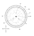
- FIG. 5 is a schematic cross-sectional view taken along the line BB shown in FIG. 3 of the cartridge accommodating portion CS.
- the surface 26s (the end surface of the first cartridge 20 on the bottom wall portion 13ab side) of the lower end portion 26 of the first cartridge 20 that comes into contact with the bottom surface 13as of the cartridge accommodating portion CS is shown by a broken line. Shows.
- FIG. 5 shows a state in which the center CP1 (position of the center line) of the first cartridge 20 and the center CP2 (position of the center line) of the cartridge accommodating portion CS coincide with each other.
- the gap between the inner peripheral surface of the cartridge accommodating portion CS and the outer peripheral surface of the first cartridge 20 is very small, and when the first cartridge 20 is accommodated in the cartridge accommodating portion CS, the center is as shown in FIG.
- the CP1 and the central CP2 are configured to substantially coincide with each other.
- the plate electrode 261 included in the first electrode portion has a substantially semicircular shape in which both ends of the arc are connected by a straight line, and has a notch 261a in the center of the arc portion.
- the plate electrode 262 included in the first electrode portion has a substantially semicircular shape in which both ends of the arc are connected by a straight line, and has a notch 262a in the center of the arc portion.
- the plate electrode 261 and the plate electrode 262 are arranged so as to face each other with the center CP1 of the first cartridge 20 interposed therebetween so that the center CP1 overlaps the straight line connecting the notch 261a and the notch 262a.
- the plate electrode 261 and the plate electrode 262 have the same shape, and when one of the plate electrode 261 and the plate electrode 262 is rotated 180 degrees around the center CP1, they are arranged so as to overlap the other of the plate electrode 261 and the plate electrode 262. ing. That is, the plate electrode 261 and the plate electrode 262 are in a point-symmetrical relationship with the central CP1 as the point of symmetry.
- FIG. 5 shows a virtual circle CR1 centered on the center CP2 of the cartridge accommodating portion CS.
- the diameter of the virtual circle CR1 is larger than the distance D1 between the plate electrode 261 and the plate electrode 262. Further, the diameter of the virtual circle CR1 is smaller than the distance D2 between the notch 261a and the notch 262a.
- the notch 261a and the notch 262a are not essential and can be omitted.
- the diameter of the virtual circle CR1 may be larger than the distance D1 and smaller than the length of the line segment connecting the center CP1 and one point on the arc of the plate electrode 261.
- the projecting electrode 411, the projecting electrode 412, and the projecting electrode 413 included in the second electrode portion are arranged on the virtual circle CR1 at equal intervals in the circumferential direction of the virtual circle CR1. That is, the angle between the line segment connecting the projecting electrode 411 and the center CP2 and the line segment connecting the projecting electrode 412 and the center CP2 is 120 degrees, and the line segment connecting the projecting electrode 412 and the center CP2 and the projecting electrode 413 The angle formed by the line segment connecting the central CP2 is 120 degrees, and the angle formed by the line segment connecting the projecting electrode 413 and the central CP2 and the line segment connecting the projecting electrode 411 and the central CP2 is 120 degrees.
- the projecting electrode 411, the projecting electrode 412, and the projecting electrode 413 included in the second electrode portion may not be arranged at equal intervals on the virtual circle CR1.
- at least one protruding electrode abuts on the plate electrode 261 and the plate electrode is in contact with any position where the rotation position of the first cartridge 20 can be taken.
- the projecting electrode 411, the projecting electrode 412, and the projecting electrode 413 may be arranged so that at least one projecting electrode abuts on the 262.
- the first cartridge 20 can be rotated by the cartridge accommodating portion CS. That is, there is no limitation on the insertion posture of the first cartridge 20 into the cartridge accommodating portion CS (rotational position of the first cartridge 20 in the circumferential direction). Therefore, depending on how the first cartridge 20 is inserted into the cartridge accommodating portion CS, as shown in FIGS. 6 to 8, the first cartridge 20 is accommodated in a state where the first cartridge 20 is rotated clockwise more than in the state of FIG. May be done.
- the projecting electrode 411, the projecting electrode 412, and the projecting electrode 413 are arranged at equal intervals on the virtual circle CR1. Therefore, when the first cartridge 20 rotates 360 degrees around the center CP1, each of the plate electrode 261 and the plate electrode 262 has one or two of the protrusion electrode 411, the protrusion electrode 412, and the protrusion electrode 413. One always touches.
- the second electrode portion provided in the cartridge accommodating portion CS has the second electrode portion on each electrode of the first electrode portion regardless of the rotation position of the first cartridge 20 in the cartridge accommodating portion CS. At least one electrode is arranged so as to be in contact with each other.
- the second cartridge 30 stores the flavor source 31.
- the second cartridge 30 is detachably housed in the cartridge accommodating portion 17b provided in the mouthpiece 17.
- the second cartridge 30 imparts flavor to the aerosol by passing the aerosol generated by atomizing the aerosol source 22 by the load 21 through the flavor source 31.
- the raw material piece constituting the flavor source 31 chopped tobacco or a molded product obtained by molding the tobacco raw material into granules can be used.
- the flavor source 31 may be composed of plants other than tobacco (for example, mint, Chinese herbs, herbs, etc.). A fragrance such as menthol may be added to the flavor source 31.
- the aerosol aspirator 1 can generate an aerosol to which a flavor is added by the aerosol source 22, the flavor source 31, and the load 21. That is, the aerosol source 22 and the flavor source 31 constitute an aerosol generation source that generates an aerosol to which a flavor is added.
- composition of the aerosol generation source used in the aerosol aspirator 1 is such that the aerosol source 22 and the flavor source 31 are separate bodies, and the substance that can be contained in the flavor source 31 by omitting the flavor source 31 is an aerosol.
- a configuration added to the source 22, a configuration in which a drug or the like is added to the aerosol source 22 instead of the flavor source 31 may be used.
- the intake sensor 15 detects the puff operation and inputs an aerosol generation request to the MCU 50.
- the MCU 50 controls the discharge from the power supply 12 to the load 21 to generate an aerosol.
- the air flowing in from the air intake port 11i provided in the power supply unit case 11 due to the suction of the user is between the through hole 13b and the projecting electrodes 411, 412, 413. It flows into the cartridge accommodating portion CS through the formed gap. This air flows into the inside of the first cartridge 20 through a minute hole (not shown) formed in the lower end portion 26 of the first cartridge 20 and passes near the load 21.
- the load 21 atomizes the aerosol source 22 drawn from the reservoir 23 by the wick 24.
- the aerosol generated by atomization flows through the aerosol flow path 25 together with the air flowing in from the micropores, and is supplied to the second cartridge 30 via the communication passage 17c.
- the aerosol supplied to the second cartridge 30 is given a flavor by passing through the flavor source 31, and is supplied to the mouthpiece 32.
- the aerosol aspirator 1 is provided with a notification unit 45 for notifying various information (see FIG. 2).
- the notification unit 45 may be configured by a light emitting element, a vibrating element, or a sound output element.
- the notification unit 45 may be a combination of two or more elements among the light emitting element, the vibration element, and the sound output element.
- the notification unit 45 may be provided in any of the power supply unit 10, the first cartridge 20, and the second cartridge 30, but it is preferably provided in the power supply unit 10, which is not a consumable item.
- an OLED (Organic Light Emitting Diode) panel 46 and a vibrator 47 are provided as the notification unit 45.
- OLED Organic Light Emitting Diode
- the notification unit 45 may be provided with only one of the OLED panel 46 and the vibrator 47, or may be provided with another light emitting element or the like. Further, the information notified by the OLED panel 46 and the information notified by the vibrator 47 may be different or the same.
- FIG. 9 is a schematic diagram showing the configuration of an electric circuit formed on the circuit board 60.
- the circuit board 60 is provided with a resistance measurement circuit 52, a resistance measurement circuit 53, a resistance measurement circuit 54, an energization switching circuit 51, and an MCU 50.
- the resistance measuring circuit 52 is connected to the projecting electrode 411 and the projecting electrode 412, and transmits information according to the electric resistance value R1 between the projecting electrode 411 and the projecting electrode 412 to the MCU 50.
- the resistance measuring circuit 52 for example, passes a minute current through the projecting electrode 411 and the projecting electrode 412, measures the voltage between the projecting electrode 411 and the projecting electrode 412 in that state, and uses this voltage as information according to the electric resistance value R1.
- the MCU 50 acquires the electric resistance value R1 based on this voltage.
- the resistance measuring circuit 53 is connected to the projecting electrode 411 and the projecting electrode 413, and transmits information according to the electric resistance value R2 between the projecting electrode 411 and the projecting electrode 413 to the MCU 50.
- the resistance measuring circuit 53 for example, passes a minute current through the projecting electrode 411 and the projecting electrode 413, measures the voltage between the projecting electrode 411 and the projecting electrode 413 in that state, and uses this voltage as information according to the electric resistance value R2.
- the MCU 50 acquires the electric resistance value R2 based on this voltage.
- the resistance measuring circuit 54 is connected to the projecting electrode 412 and the projecting electrode 413, and transmits information according to the electric resistance value R3 between the projecting electrode 412 and the projecting electrode 413 to the MCU 50.
- the resistance measuring circuit 54 passes a minute current through the projecting electrode 412 and the projecting electrode 413, measures the voltage between the projecting electrode 412 and the projecting electrode 413 in that state, and uses this voltage as information according to the electric resistance value R3.
- the MCU 50 acquires the electric resistance value R3 based on this voltage.
- the MCU 50 functions as a resistance measuring unit that acquires the electric resistance values R1, R2, and R3 based on the information from the resistance measuring circuits 52, 53, and 54.
- the electric resistance values R1 and R2 cannot be measured, and the electric resistance value R3 becomes a value close to the electric resistance value of the load 21.
- the electric resistance values R2 and R3 cannot be measured, and the electric resistance value R1 becomes a value close to the electric resistance value of the load 21.
- the electric resistance values R1 and R3 cannot be measured, and the electric resistance value R2 becomes a value close to the electric resistance value of the load 21.
- the electric resistance value R3 is a minute value, and the electric resistance values R1 and R2 are close to the electric resistance value of the load 21, respectively.
- the energization switching circuit 51 includes a switch and the like, and supplies the power supplied from the power supply 12 to the electrode pair of the protrusion electrode 411 and the protrusion electrode 412, and supplies the power to the electrode pair of the protrusion electrode 412 and the protrusion electrode 413. The state of supplying the power to the electrode pair of the projecting electrode 411 and the projecting electrode 413 is switched.
- the MCU 50 determines an electrode pair to which electric power from the power source 12 (including at least electric power for atomizing the aerosol source 22) to be supplied is determined based on the electric resistance values R1, R2, and R3, and the determined electrode pair is used.
- the energization switching circuit 51 is controlled so that power is supplied.
- the MCU 50 selects an electrode pair whose electrical resistance value between the electrodes is equal to or higher than the threshold value based on the electrical resistance values R1, R2, and R3.
- the electrode pair of the projecting electrode 412 and the projecting electrode 413 is selected.
- the electrode pair of the projecting electrode 411 and the projecting electrode 412 is selected.
- the electrode pair of the projecting electrode 411 and the projecting electrode 413 is selected.
- one of the electrode pair of the projecting electrode 411 and the projecting electrode 412 and the electrode pair of the projecting electrode 411 and the projecting electrode 413 is selected.
- the information on the actual energization may be accumulated for each projecting electrode, and the electrode pair including the projecting electrode having the smallest number of times of energization may be selected.
- another threshold value higher than the above threshold value may be set, and an electrode pair having an electric resistance value less than this other threshold value may be selected from a plurality of electrode pairs having an electric resistance value equal to or higher than the threshold value. ..
- a target value of the electric resistance value may be set, and the electrode pair whose electric resistance value between the electrodes is closest to this target value may be selected.
- the cartridge accommodating portion CS does not have a positioning mechanism for positioning the circumferential position of the first cartridge 20. Therefore, the first cartridge 20 can be inserted into the cartridge accommodating portion CS without being aware of the rotational posture of the first cartridge 20. Therefore, the operability of mounting the first cartridge 20 on the power supply unit 10 can be improved.
- the power supply unit 10 is provided with a second electrode portion including a number of electrodes larger than the number of electrodes of the first electrode portion. Therefore, regardless of the rotational posture of the first cartridge 20, the first cartridge 20 and the power supply unit 10 can be electrically connected, and aerosol generation can be performed in the same manner as in the conventional case. ..
- the electrode pair to be energized for aerosol generation is selected based on the electric resistance value between the protruding electrodes of the second electrode portion. For example, even in any of the states of FIGS. 5 to 7, a projecting electrode in contact with each of the plate electrodes 261 and 262 can be selected and energized to generate an aerosol. .. Further, in the state of FIG. 8, the electrode pair of the protruding electrodes 412 and 413 in contact with the plate electrode 262 is short-circuited, but the electrode pair is not energized. In this way, it is possible to prevent the large power required for aerosol generation from being supplied to the short-circuited electrode pair, and it is possible to improve safety. As described above, even if the number of electrodes included in the second electrode portion is three, an appropriate two are selected from these and energization is performed. Therefore, even if there is no positioning mechanism, aerosol generation can be safely performed as in the conventional case.
- the timing at which the MCU 50 acquires the electric resistance values R1, R2, and R3 is from the time when the power of the aerosol aspirator 1 is turned on by the operation of the operation unit 18 to the time when the first aerosol generation request is received (in other words,). , The period during which the aerosol source 22 is not atomized). By doing so, the electric resistance values R1, R2, and R3 are measured before supplying a large amount of electric power for aerosol generation to the first cartridge 20, and the electrode pair to be energized in the second electrode portion is determined. Can be done. Therefore, aerosol generation can be safely performed.
- FIG. 10 is a schematic view showing a first modification of the cartridge accommodating portion CS, and is a schematic cross-sectional view corresponding to FIG.
- the configuration of FIG. 10 is the same as that of FIG. 5 except that the positions of the protruding electrodes 412 provided on the bottom wall portion 13ab of the cartridge accommodating portion CS are different.
- FIG. 10 shows a virtual circle CR2 centered on the center CP2 of the cartridge accommodating portion CS.
- the virtual circle CR2 has a smaller diameter than the virtual circle CR1 and is located inside the virtual circle CR2.
- the diameter of the virtual circle CR2 is larger than the distance D1 described above.
- the protruding electrode 412 is arranged on the virtual circle CR2.
- the angle formed by the line segment connecting the projecting electrode 411 and the center CP2 and the line segment connecting the projecting electrode 412 and the center CP2 is 120 degrees, and the line segment connecting the projecting electrode 412 and the center CP2
- the angle between the projecting electrode 413 and the line segment connecting the center CP2 is 120 degrees, and the angle between the line segment connecting the projecting electrode 413 and the center CP2 and the line segment connecting the projecting electrode 411 and the center CP2 is 120 degrees.
- first cartridge 20 having an annular first annular electrode overlapping the peripheral edge of the virtual circle CR1 and an annular second annular electrode overlapping the peripheral edge of the virtual circle CR2 as the first electrode portion is provided in the cartridge accommodating portion CS. It is assumed that it can be housed in and used.
- the protruding electrodes 411 and 413 can always be brought into contact with the first annular electrode regardless of the rotational posture of the first cartridge 20 of the other type, and the second The protruding electrode 412 can always be brought into contact with the annular electrode.
- the electrical resistance values between the projecting electrodes 411 and 412 and the electrical resistance values between the projecting electrodes 412 and 413 are high. Each becomes equal to or more than the threshold value, and the electric resistance value between the protruding electrodes 411 and 413 becomes less than the threshold value.
- the MCU 50 controls the electrode pair of the projecting electrode 412 and the projecting electrode 411 or the electrode pair of the projecting electrode 412 and the projecting electrode 413 so that the electrode from the power supply 12 is supplied to the first of the above-mentioned different types.
- the cartridge 20 can be energized to generate an aerosol. As described above, according to the configuration of FIG. 10, the aerosol suction device 1 compatible with various types of the first cartridge 20 can be realized, and the commercial value can be enhanced.
- the projecting electrode 411 and the projecting electrode 413 are arranged point-symmetrically with respect to the center CP2, so that the first cartridge 20 of the type shown in FIG. 4 and the other type of the above are different. It becomes possible to identify which of the cartridge 20 is mounted. Specifically, the MCU 50 first acquires the first electric resistance value between the protruding electrodes 411 and 413, and if the first electric resistance value is equal to or higher than the threshold value, the first cartridge 20 of the type shown in FIG. 4 is used. Recognize that it is attached.
- the MCU 50 acquires the second electric resistance value between the protruding electrodes 411 and 421 or the second electric resistance value between the protruding electrodes 413 and 421, and obtains the second electric resistance value. If is equal to or greater than the threshold value, it is recognized that the first cartridge 20 of the other type is attached. If the second electric resistance value is less than the threshold value, the MCU 50 determines that it is a connection error and notifies the user. The MCU 50 may notify the user of the recognized cartridge type. Further, the MCU 50 may change the discharge control to the first cartridge 20 according to the cartridge type. In this way, the commercial value of the aerosol aspirator 1 can be enhanced by making it possible to use different types of cartridges and performing optimum control according to the cartridge type.
- FIG. 11 is a schematic view showing a second modification of the cartridge accommodating portion CS, and is a schematic cross-sectional view corresponding to FIG.
- the configuration of FIG. 11 is that the positions of the protruding electrodes 411, 421, and 413 provided on the bottom wall portion 13ab of the cartridge accommodating portion CS are different, and that the protruding electrodes 414 are additionally provided on the bottom wall portion 13ab. Except for this, the configuration is the same as that shown in FIG.
- the virtual circle CR2 shown in FIG. 11 is the same as the virtual circle CR2 shown in FIG.
- the projecting electrodes 411 and 413 are arranged at equal intervals on the virtual circle CR1, and the projecting electrodes 412 and 414 are arranged at equal intervals on the virtual circle CR2.
- the angle formed by the two line segments connecting each of the projecting electrodes 411 and 412 and the center CP2 the angle formed by the two line segments connecting each of the projecting electrodes 412 and 413 and the center CP2, the projecting electrode 413,
- the angle formed by the two line segments connecting each of the 414s and the central CP2 and the angle formed by the two line segments connecting each of the protruding electrodes 414 and 411 and the central CP2 are 90 degrees, respectively.
- the MCU 50 has an electric resistance value between the electrodes of the electrode pair of the projecting electrode 411 and the projecting electrode 412, an electric resistance value between the electrodes of the electrode pair of the projecting electrode 411 and the projecting electrode 413, and the projecting electrode.
- the value and the electric resistance value between the electrodes of the electrode pair of the projecting electrode 413 and the projecting electrode 414 are acquired, respectively.
- the MCU 50 selects one electrode pair whose acquired electric resistance value is equal to or higher than the threshold value, and controls the electrode pair to supply electric power from the power supply 12.
- the same effect as that of FIGS. 5 and 10 can be obtained.
- the number of protruding electrodes included in the second electrode portion is larger than that of the configurations of FIGS. 5 and 10. Therefore, it is possible to have a plurality of electrode pairs having an electric resistance value equal to or higher than the threshold value with high probability. Therefore, for example, it becomes easy to select an electrode pair so that each protruding electrode is evenly used for energization, and the durability of the second electrode portion can be improved. Further, according to the configuration of FIG.
- the projecting electrode 411 and the projecting electrode 413 are arranged point-symmetrically with respect to the central CP2, and the projecting electrode 412 and the projecting electrode 414 are arranged point-symmetrically with respect to the central CP2.
- the first cartridge 20 of the type shown in 4 and the first cartridge 20 of the other type can be distinguished from each other, and the commercial value can be enhanced.
- the protruding electrodes 411, 421, 413, and 414 may be arranged at equal intervals on either the virtual circle CR1 or the virtual circle CR2.
- FIG. 12 is a schematic view showing a third modification of the cartridge accommodating portion CS, and is a schematic cross-sectional view corresponding to FIG.
- the configuration of FIG. 12 is the same as that of FIG. 11 except that the positions of the protruding electrodes 411 and 414 are changed.
- the projecting electrode 411 is arranged on the virtual circle CR2, and the projecting electrode 414 is arranged on the virtual circle CR1.
- the angle formed by the two line segments connecting each of the projecting electrodes 411 and 412 and the center CP2 the angle formed by the two line segments connecting each of the projecting electrodes 412 and 413 and the center CP2, the projecting electrode 413,
- the angle formed by the two line segments connecting each of the 414s and the central CP2 and the angle formed by the two line segments connecting each of the protruding electrodes 414 and 411 and the central CP2 are 90 degrees, respectively.
- the position of the protruding electrode 412 may be changed to the central CP2. Further, in the configurations of FIGS. 11 and 12, the position of the protruding electrode 412 or the protruding electrode 414 may be changed to the central CP2.
- the first cartridge 20 a second type having a first electrode portion in which a circular electrode is arranged in the central CP1 and an annular electrode is arranged on the virtual circle CR1 is assumed. According to the configuration in which the position of the protruding electrode 412 is changed to the central CP2 in the configuration of FIG. 10 and the position of the protruding electrode 412 or the protruding electrode 414 is changed to the central CP2 in the configurations of FIGS.
- the distance between the electrode pairs is changed.
- the electrode pair to be energized based on the electric resistance value of the above, it becomes possible to correspond to both the first cartridge 20 of the type shown in FIG. 4 and the first cartridge 20 of the second different type.
- the type can be identified based on the electric resistance value between the electrode pairs.
- FIG. 13 is a diagram showing a fourth modification of the cartridge accommodating portion CS, and is a schematic cross-sectional view corresponding to FIG.
- the configuration of FIG. 13 is the same as that of FIG. 3 except that the annular member 131 is provided on the bottom wall portion 13ab.
- FIG. 14 is a schematic cross-sectional view taken along the line BB of FIG.
- FIG. 15 is a diagram schematically showing an exploded perspective of the bottom wall portion 13ab of the cartridge accommodating portion CS of FIG.
- annular recess 130 having a shape along the outer peripheral edge of the bottom wall portion 13ab is formed on the bottom surface 13as of the cartridge accommodating portion CS.
- the annular recess 130 is formed so as to surround a region in which a through hole 13b for passing through the projecting electrodes 411, 412, and 413 is formed.
- the annular member 131 is arranged in the annular recess 130 in a non-fixed state.
- the non-fixed state refers to a state different from the state in which the annular recess 130 and the annular member 131 are firmly fixed by adhesion, press fitting, or the like, and refers to a state in which the annular member 131 can be removed from the annular recess 130.
- the annular member 131 is fitted into the annular recess 130 in such a state that it can rotate in the annular recess 130 if a strong force is applied in the circumferential direction thereof.
- the annular member 131 is a flexible member made of a soft material such as urethane, silicon, resin, or rubber.
- the annular member 131 is composed of a member whose rigidity is sufficiently lower than the rigidity of the lower end portion 26 of the first cartridge 20.
- the coefficient of static friction between the surface 26s of the lower end portion 26 of the first cartridge 20 and the annular member 131 is large enough to prevent the first cartridge 20 from rotating inside the cartridge accommodating portion CS.
- the inner diameter of the annular member 131 is smaller than the diameter of the first cartridge 20, and the annular member 131 is configured to be in contact with the surface 26s of the first cartridge 20 in the circumferential direction thereof. Further, it is preferable that the height of the annular member 131 in the vertical direction is larger than the depth of the annular recess 130 in the vertical direction. It is more preferable that the upper surface of the annular member 131 is located between the tips of the protruding electrodes 411, 412 and 413 and the bottom surface 13as of the cartridge accommodating portion CS.
- the annular member 131 is embedded in the bottom wall portion 13ab in a state of being exposed in the cartridge accommodating portion CS. Therefore, even if a force that rotates in the circumferential direction is applied to the first cartridge 20 in a state where the first cartridge 20 is housed in the cartridge accommodating portion CS, the rotation of the first cartridge 20 due to the force is with the annular member 131. It is suppressed by the frictional force between the first cartridges 20. By suppressing the rotation of the first cartridge 20 in this way, it is possible to prevent wear of the first cartridge 20 and the cartridge accommodating portion CS due to friction.
- the projecting electrode 411 and the projecting electrode 412 are used to energize the first cartridge 20. If the first cartridge 20 rotates during this energization and the protruding electrode 412 and the plate electrode 261 come into contact with each other, a short circuit occurs. By suppressing the rotation of the first cartridge 20, it is possible to prevent the occurrence of such a short circuit.
- the annular member 131 is arranged in a non-fixed state on the bottom wall portion 13ab of the cartridge accommodating portion CS. Therefore, a gap is formed between the annular member 131 and the bottom wall portion 13ab of the cartridge accommodating portion CS.
- the aerosol source 22 leaking from the first cartridge 20 can be collected by the capillary force due to this gap. As a result, it is possible to prevent the aerosol source 22 from invading the region where the protruding electrode or the plate electrode is arranged, and it is possible to improve durability and safety.
- the annular member 131 has a function of suppressing the rotation of the first cartridge 20.
- any configuration may be used as long as it can generate a frictional force between the bottom wall portion 13ab and the first cartridge 20.
- a plurality of arc-shaped flexible members may be arranged in the annular recess 130.
- a part or all of the surface (upper surface 131sa (see FIG. 15)) of the annular member 131 on the first cartridge 20 side is an uneven surface.
- a part or all of the surface (lower surface 131sb (see FIG. 15)) on the bottom wall portion 13ab side of the annular member 131 is an uneven surface.
- the coefficient of static friction between the annular member 131 and the bottom surface 130b of the annular recess 130 can be increased, and the annular member 131 can be prevented from rotating.
- the unevenness of the lower surface 131sb of the annular member 131 can increase the capillary force to enhance the collecting effect of the aerosol source 22.
- a part or all of the bottom surface 130b of the annular recess 130 is an uneven surface.
- the coefficient of static friction between the annular member 131 and the bottom surface 130b can be increased, and the annular member 131 can be prevented from rotating.
- the unevenness of the bottom surface 130b can increase the capillary force to enhance the collecting effect of the aerosol source 22.
- FIG. 16 is a schematic cross-sectional view showing a modified example of the cross section taken along the line CC of FIG.
- at least one recess 131b is formed on the lower surface 131sb of the annular member 131
- a convex portion 130c that engages with each recess 131b of the annular member 131 is formed on the bottom surface 130b of the annular recess 130.
- the concave portion 131b and the convex portion 130c engaged with the concave portion 131b have, for example, a cylindrical shape or a rectangular parallelepiped shape, respectively.
- the annular member 131 and the bottom wall portion 13ab of the cartridge accommodating portion CS are engaged with the concave portion 131b by the convex portion 130c. Therefore, it is possible to suppress the rotation of the annular member 131.
- the same effect can be obtained by forming a convex portion on the lower surface 131sb of the annular member 131 and forming a concave portion engaging with the convex portion on the bottom surface 130b of the annular recess 130.
- a plurality of pairs of the concave portion 131b and the convex portion 130c are arranged side by side in the circumferential direction.
- FIG. 17 is a schematic cross-sectional view showing another modified example of the cross section taken along the line CC of FIG.
- at least one recess 131a is formed on the outer peripheral side surface 131sc of the annular member 131, and the wall surface 130s facing the outer peripheral side surface 131sc of the annular recess 130 engages with each recess 131a of the annular member 131.
- the convex portion 130a is formed.
- the concave portion 131a and the convex portion 130a engaged with the concave portion 131a are, for example, cylindrical, rectangular parallelepiped, annular, or the like, respectively.
- the annular member 131 and the wall surface 130s of the cartridge accommodating portion CS are engaged by the concave portion 131a and the convex portion 130a. Therefore, it is possible to restrict the annular member 131 from moving in the vertical direction. Therefore, it is possible to prevent the annular member 131 from being lifted by the aerosol source 22 collected between the annular member 131 and the bottom surface 130b of the annular recess 130.
- the same effect can be obtained by forming a convex portion on the outer peripheral side surface 131 sc of the annular member 131 and forming a concave portion engaged with the convex portion on the wall surface 130s of the annular concave portion 130.
- the concave portion 131a and the convex portion 130a each have an annular shape along the circumferential direction.
- a convex portion or a concave portion is formed on the inner peripheral side surface 131sd of the annular member 131, and a concave portion or a convex portion engaged with the convex portion or the concave portion is provided on the wall surface of the annular concave portion 130 facing the inner peripheral side surface 131sd. May be. Even with this configuration, it is possible to prevent the annular member 131 from rising.
- two electrodes are provided on the first cartridge 20.
- the number of electrodes provided in the first cartridge 20 is not limited to two.
- a heater for heating the flavor source 31 is added to the first cartridge 20, and a total of four electrodes, two electrodes for energizing the heater and two electrodes for energizing the load 21, are added to the first cartridge. It may be provided in 20.
- the first cartridge 20 may be provided with two heaters for heating the aerosol source 22, and the first cartridge 20 may be provided with a total of four electrodes for energizing each of the two heaters.
- the number of protruding electrodes provided in the cartridge accommodating portion CS may be five or more, which is more than four. By doing so, regardless of the rotational position of the first cartridge 20, the electrodes included in the second electrode portion are brought into contact with each electrode included in the first electrode portion, and the first electrode is used.
- the two heaters of the cartridge 20 can be individually energized.
- At least a part of the region that can come into contact with the annular member 131 is an uneven surface on the surface 26s of the lower end portion 26 of the first cartridge 20. By doing so, it is possible to enhance the rotation suppressing effect and the capillary force of the annular member 131.
- the upper end opening of the cartridge accommodating portion CS is closed by the second cartridge 30.
- a configuration can be adopted in which the lower end opening of the cartridge holder 14 is closed. ..
- a second electrode portion may be provided on the lid portion so that the first electrode portion and the second electrode portion are electrically connected when the lid portion is closed.
- the cartridge holder 14 and the lid portion constitute an accommodating portion for accommodating the first cartridge 20.
- a bottomed cylindrical housing unit (cartridge storage unit CS) that stores a columnar cartridge (first cartridge 20) that stores an aerosol source (aerosol source 22) in a state where it can rotate 360 degrees in the circumferential direction of the cartridge.
- the bottom portion (bottom wall portion 13ab) of the accommodating portion is provided with a rotation suppressing portion (annular member 131) that generates frictional force with the cartridge to suppress the rotation of the cartridge in the circumferential direction.
- Power supply unit power supply unit 10) of the aerosol generator (aerosol suction device 1).
- the rotation suppressing portion is a power supply unit of an aerosol generating device, which is composed of an annular member (annular member 131) along the outer periphery of the bottom portion.
- the rotation suppressing portion is composed of the annular member, the frictional force generated between the cartridge and the cartridge when the cartridge rotates can be increased. Therefore, the effect of suppressing the rotation of the cartridge can be enhanced.
- the power supply unit of the aerosol generator described above is a power supply unit of an aerosol generator composed of a flexible member.
- the function of the rotation suppressing unit can be easily realized, and the manufacturing cost can be suppressed.
- a power supply unit for an aerosol generator wherein at least a part of the cartridge-side surface (upper surface 131sa) of the annular member is an uneven surface.
- the frictional force with respect to the cartridge can be increased by the uneven surface of the annular member. Therefore, the effect of suppressing the rotation of the cartridge can be enhanced.
- the power supply unit of the aerosol generator according to any one of (2) to (4).
- the annular member is a power supply unit of an aerosol generator, which is arranged in a non-fixed state on the bottom of the accommodating portion.
- a gap is formed between the annular member and the bottom of the accommodating portion. Therefore, the aerosol source leaked from the cartridge can be collected by the capillary force due to this gap.
- a power supply unit of the aerosol generator according to the description.
- a first engaging recess (recess 131b) is formed on the bottom surface of the annular member.
- a first engaging convex portion is formed on the bottom surface of the annular member.
- a power supply unit of an aerosol generator in which a concave portion that engages with the first engaging convex portion of the annular member is formed in a region of the bottom portion of the accommodating portion facing the annular member.
- a second engaging recess (recessed 131a) is provided on the peripheral side surface (outer peripheral side surface 131sc or inner peripheral side surface) of the annular member.
- the axial movement of the annular member can be restricted by the engaging force between the second engaging concave portion and the convex portion of the accommodating portion. Therefore, it is possible to prevent the annular member from being lifted by the aerosol source collected between the annular member and the accommodating portion by this engaging force.
- the power supply unit of the aerosol generator according to any one of (5) to (8).
- a second engaging convex portion is provided on the peripheral side surface (outer peripheral side surface 131 sc or inner peripheral side surface) of the annular member.
- a power supply unit for an aerosol generator, wherein the accommodating portion is provided with a concave portion that engages with the second engaging convex portion.
- the axial movement of the annular member can be restricted by the engaging force between the second engaging convex portion and the concave portion of the accommodating portion. Therefore, it is possible to prevent the annular member from being lifted by the aerosol source collected between the annular member and the accommodating portion by this engaging force.
- a frictional force can be generated between the cartridge and the accommodating portion due to the unevenness of the cartridge. Both this frictional force and the frictional force of the rotation restraining portion can firmly prevent the cartridge from rotating in the accommodating portion.
- Aerosol aspirator 20 1st cartridge 22 Aerosol source CS cartridge accommodating part 131 Circular member
Landscapes
- Health & Medical Sciences (AREA)
- Engineering & Computer Science (AREA)
- Animal Behavior & Ethology (AREA)
- Anesthesiology (AREA)
- Biomedical Technology (AREA)
- Heart & Thoracic Surgery (AREA)
- Hematology (AREA)
- Life Sciences & Earth Sciences (AREA)
- General Health & Medical Sciences (AREA)
- Public Health (AREA)
- Veterinary Medicine (AREA)
- Pulmonology (AREA)
- Bioinformatics & Cheminformatics (AREA)
- Containers And Packaging Bodies Having A Special Means To Remove Contents (AREA)
Abstract
エアロゾル生成装置(1)の電源ユニット(10)は、エアロゾル源(22)を貯留する柱状の第1カートリッジ(20)を周方向に360度回転可能な状態にて収容する有底筒状のカートリッジ収容部CSを備え、カートリッジ収容部CSの底壁部(13ab)には、第1カートリッジ(20)との間で摩擦力を発生させて第1カートリッジ(20)の上記周方向への回転を抑制する環状部材(131)が設けられる。
Description
本発明は、エアロゾル生成装置の電源ユニット、エアロゾル生成装置に関する。
特許文献1には、エアロゾル源を収容するカートリッジと、前記カートリッジを収容する有底筒状のカートリッジ収容部と、前記カートリッジ収容部に螺着し、前記エアロゾル源が霧化したエアロゾルを吸引する吸引口が形成された吸口部と、前記吸口部の前記カートリッジ収容部に対する螺着に連動して、前記カートリッジを前記カートリッジ収容部に対して位置決めする位置決め機構と、を有するエアロゾル生成装置が記載されている。
エアロゾル源を収容するカートリッジをカートリッジ収容部に装着する際の操作性を向上させるために、特許文献1に例示されるような位置決め機構を無くすことが想定される。しかし、位置決め機構がなくなると、カートリッジ収容部においてカートリッジが自由に回転できることになる。このため、カートリッジが回転することによるカートリッジ収容部やカートリッジの摩耗への対策が必要になる。
本発明の目的は、位置決め機構を用いることなく、操作性向上と部材の摩耗の防止を両立させることのできるエアロゾル生成装置を提供することにある。
本発明の一態様のエアロゾル生成装置の電源ユニットは、エアロゾル源を貯留する柱状のカートリッジを上記カートリッジの周方向に360度回転可能な状態にて収容する有底筒状の収容部を備え、上記収容部の底部には、上記カートリッジとの間で摩擦力を発生させて上記カートリッジの上記周方向への回転を抑制する回転抑制部が設けられる、ものである。
本発明によれば、位置決め機構を用いることなく、操作性向上と部材の摩耗の防止を両立させることのできるエアロゾル生成装置を提供することができる。
以下、本発明の一実施形態であるエアロゾル生成装置の電源ユニットについて説明する。先ず、本実施形態の電源ユニットを備えるエアロゾル生成装置の一例であるエアロゾル吸引器について、図1~図3を参照しながら説明する。
(エアロゾル吸引器)
エアロゾル吸引器1は、燃焼を伴わずに香味が付加されたエアロゾルを生成し、生成したエアロゾルを吸引するための器具であり、手中におさまるサイズであることが好ましく、略直方体形状を有する。なお、エアロゾル吸引器1は、卵型形状、楕円形状等であってもよい。以下の説明では、略直方体形状のエアロゾル吸引器において、直交する3方向のうち、長さの長い順から、上下方向、前後方向、左右方向と称する。また、以下の説明では、便宜上、図1~図3に記載したように、前方、後方、左方、右方、上方、下方を定義し、前方をFr、後方をRr、左側をL、右側をR、上方をU、下方をD、として示す。
エアロゾル吸引器1は、燃焼を伴わずに香味が付加されたエアロゾルを生成し、生成したエアロゾルを吸引するための器具であり、手中におさまるサイズであることが好ましく、略直方体形状を有する。なお、エアロゾル吸引器1は、卵型形状、楕円形状等であってもよい。以下の説明では、略直方体形状のエアロゾル吸引器において、直交する3方向のうち、長さの長い順から、上下方向、前後方向、左右方向と称する。また、以下の説明では、便宜上、図1~図3に記載したように、前方、後方、左方、右方、上方、下方を定義し、前方をFr、後方をRr、左側をL、右側をR、上方をU、下方をD、として示す。
図1~図3に示すように、エアロゾル吸引器1は、電源ユニット10と、第1カートリッジ20と、第2カートリッジ30と、を備える。第1カートリッジ20及び第2カートリッジ30は、電源ユニット10に対して着脱可能である。言い換えると、第1カートリッジ20及び第2カートリッジ30は、それぞれ交換可能である。図4に示すように、第1カートリッジ20は、外形が円柱状となっている。第1カートリッジ20の外形は、完全な円柱状となっていなくてもよい。例えば、正十六角形等の正多角形の多角注状やその角を丸めた柱状等であってもよい。
(電源ユニット)
電源ユニット10は、図1及び図2に示すように、略直方体形状の電源ユニットケース11の内部(以下、ケース内部とも称する)に、電源12、内部ホルダ13、回路基板60、吸気センサ15等の各種センサ等を収容する。電源12や回路基板60(後述のMCU(Micro Controller Unit)50、通電切替回路51、抵抗測定回路52、抵抗測定回路53、抵抗測定回路54、突電極411、突電極412、突電極413、充電端子43等を含む)等がまとめて電源ユニットケース11に収容されることで、ユーザによる持ち運びを容易にし、ユーザの利便性の向上を図れる。
電源ユニット10は、図1及び図2に示すように、略直方体形状の電源ユニットケース11の内部(以下、ケース内部とも称する)に、電源12、内部ホルダ13、回路基板60、吸気センサ15等の各種センサ等を収容する。電源12や回路基板60(後述のMCU(Micro Controller Unit)50、通電切替回路51、抵抗測定回路52、抵抗測定回路53、抵抗測定回路54、突電極411、突電極412、突電極413、充電端子43等を含む)等がまとめて電源ユニットケース11に収容されることで、ユーザによる持ち運びを容易にし、ユーザの利便性の向上を図れる。
電源ユニットケース11は、左右方向(厚さ方向)に着脱可能な第1ケース11A及び第2ケース11Bから構成される。これら第1ケース11Aと第2ケース11Bとが左右方向(厚さ方向)に組付けられることで、電源ユニット10の前面、後面、左面、右面、下面、が形成される。電源ユニット10の上面は、ディスプレイ16により形成される。
電源ユニット10の上面には、ディスプレイ16の前方にマウスピース17が設けられる。図3に示すように、マウスピース17は、吸口17aがディスプレイ16よりもさらに上方に突出する。
電源ユニット10の上面と後面との間には、後方に向かうにしたがって下方に傾斜する傾斜面が設けられる。傾斜面には、ユーザが操作可能な操作部18が設けられる。操作部18は、ボタン式のスイッチ、タッチパネル等から構成される。操作部18は、ユーザの使用意思を反映してMCU50及び各種センサを起動/遮断する際等に利用される。
電源ユニット10の下面には、電源12を充電可能な外部電源(図示省略)と電気的に接続可能な充電端子43が設けられる。充電端子43は、例えば、相手側となるプラグ(図示省略)を挿入可能なレセプタクルである。充電端子43としては、各種USB端子(プラグ)等を挿入可能なレセプタクルを用いることができる。一例として、本実施形態においては、充電端子43をUSB Type-C形状のレセプタクルとする。これにより、電源ユニット10(すなわちエアロゾル吸引器1)をさまざまな箇所(場所)で充電することを容易にし、電源ユニット10を充電できる機会を担保(確保)することができる。
また、充電端子43は、例えば、受電コイルを備え、外部電源から送電される電力を非接触で受電可能に構成されてもよい。この場合の電力伝送(Wireless Power Transfer)の方式は、電磁誘導型でもよいし、磁気共鳴型でもよいし、電磁誘導型と磁気共鳴型を組み合わせたものでもよい。別の一例として、充電端子43は、各種USB端子が接続可能であり、且つ上述した受電コイルを有していてもよい。
内部ホルダ13は、電源ユニット10の後面に沿って延びる後壁13rと、ケース内部の前後方向の中央部に設けられ後壁13rと平行に延びる中央壁13cと、ディスプレイ16に沿って延び後壁13rと中央壁13cとを連結する上壁13uと、後壁13r、中央壁13c、及び上壁13uに直交しこれら後壁13r、中央壁13c、及び上壁13uによって区画形成される空間を左側空間と右側空間に分ける隔壁13dと、中央壁13cに連結され中央壁13cの前方且つ電源ユニット10の下面よりも上方に位置するカートリッジ保持部13aと、を備える。図2及び図3に示すように、カートリッジ保持部13aは、上端側に開口を有し且つ上下方向を軸方向とする有底筒状の部材である。
内部ホルダ13の左側空間には、電源12が配置される。電源12は、充電可能な二次電池、電気二重層キャパシタ等であり、好ましくは、リチウムイオン二次電池である。電源12の電解質は、ゲル状の電解質、電解液、固体電解質、イオン液体の1つ又はこれらの組合せで構成されていてもよい。
内部ホルダ13の右側空間と、カートリッジ保持部13aと電源ユニット10の下面との間に形成された下側空間とにより形成される空間には、L字状の回路基板60が配置される。回路基板60は、複数層(本実施形態では4層)の基板が積層されて構成され、MCU50等の電子部品が搭載される。
MCU50は、パフ(吸気)動作を検出する吸気センサ15等の各種センサ装置、操作部18及び通知部45等に接続されている。MCU50は、後述の負荷21(図3参照)を加熱(エアロゾルを生成)するための負荷21への放電制御を含む、エアロゾル吸引器1の各種の制御を行う制御装置(コントローラ)である。具体的には、MCU50は、プロセッサを主体に構成されており、プロセッサの動作に必要なRAM(Random Access Memory)と各種情報を記憶するROM(Read Only Memory)等の記憶媒体をさらに含む。本明細書におけるプロセッサとは、例えば、半導体素子等の回路素子を組み合わせた電気回路である。
図3に示すように、カートリッジ保持部13aの内周部には、第1カートリッジ20を保持する円筒状のカートリッジホルダ14の下端部が配置される。カートリッジ保持部13aの底壁部13abとカートリッジホルダ14とによって、第1カートリッジ20を収容する有底筒状のカートリッジ収容部CSが構成されている。底壁部13abは、カートリッジ収容部CSの底部を構成している。底壁部13abの上面は、カートリッジ収容部CSの底面13asを構成している。
カートリッジホルダ14の内周部は、第1カートリッジ20の外形に対応した形状となっている。カートリッジホルダ14の内周面と第1カートリッジ20の外周面との間には、電源ユニット10に加わる衝撃や振動等によって、第1カートリッジ20が周方向に僅かに回転し得る程度の微小な隙間が形成されている。
カートリッジ収容部CSと第1カートリッジ20とには、カートリッジ収容部CSにおいて第1カートリッジ20の周方向(第1カートリッジ20の中心線周りの方向)の位置決めを行うための機構は設けられていない。つまり、第1カートリッジ20がカートリッジ収容部CSに収容された状態において、第1カートリッジ20に対し、これを周方向に回転させる力を加えれば、第1カートリッジ20を360度回転させることが可能となっている。
カートリッジ保持部13aの底壁部13abには、回路基板60から第1カートリッジ20に向かって突出するように設けられた突電極411、突電極412、及び突電極413(図3、5参照)の各々を受け入れる貫通孔13bが設けられる。突電極411、突電極412、及び突電極413は第二電極部を構成している。突電極411、突電極412、及び突電極413は、それぞれ、電源12と電気的に接続可能に構成されており、例えば、ばねが内蔵されたピン等により構成される。突電極411、突電極412、及び突電極413の各々に対応して設けられた貫通孔13bは、各突電極よりも大きく、貫通孔13bと各突電極との間に形成される隙間を介して、第1カートリッジ20の内部に空気が流入するように構成される。
図2に示すように、カートリッジホルダ14の外周面14aには、回路基板60と対向する位置にパフ動作を検出する吸気センサ15が設けられている。吸気センサ15は、コンデンサマイクロフォンや圧力センサ等から構成されていてもよい。カートリッジホルダ14には、第1カートリッジ20の内部に貯留されるエアロゾル源22の残量を目視可能な上下方向に長い穴部14bが設けられる。図1に示すように、電源ユニットケース11には、透光性を有する残量確認窓11wが形成されている。この残量確認窓11wから、第1カートリッジ20の穴部14bを通して、第1カートリッジ20の内部に貯留されるエアロゾル源22の残量が目視できるように構成されている。この残量確認窓11wには、ケース内部に外気を取り込む空気取込口11iが設けられている。
図3に示すように、カートリッジホルダ14の上端部には、マウスピース17が着脱自在に固定される。マウスピース17には、第2カートリッジ30が着脱自在に固定される。マウスピース17は、第2カートリッジ30の一部を収容するカートリッジ収容部17bと、第1カートリッジ20とカートリッジ収容部17bとを連通させる連通路17cと、を備える。
(第1カートリッジ)
第1カートリッジ20は、図3に示すように、円筒状のカートリッジケース27の内部に、エアロゾル源22を貯留するリザーバ23と、エアロゾル源22を霧化する電気的な負荷21と、リザーバ23から負荷21へエアロゾル源を引き込むウィック24と、エアロゾル源22が霧化されることで発生したエアロゾルが第2カートリッジ30に向かって流れるエアロゾル流路25と、を備える。
第1カートリッジ20は、図3に示すように、円筒状のカートリッジケース27の内部に、エアロゾル源22を貯留するリザーバ23と、エアロゾル源22を霧化する電気的な負荷21と、リザーバ23から負荷21へエアロゾル源を引き込むウィック24と、エアロゾル源22が霧化されることで発生したエアロゾルが第2カートリッジ30に向かって流れるエアロゾル流路25と、を備える。
リザーバ23は、エアロゾル流路25の周囲を囲むように区画形成され、エアロゾル源22を貯留する。リザーバ23には、樹脂ウェブ又は綿等の多孔体が収容され、且つ、エアロゾル源22が多孔体に含浸されていてもよい。リザーバ23には、樹脂ウェブ又は綿上の多孔質体が収容されず、エアロゾル源22のみが貯留されていてもよい。エアロゾル源22は、グリセリン、プロピレングリコール、又は水等の液体を含む。
ウィック24は、リザーバ23から毛管現象を利用してエアロゾル源22を負荷21へ引き込む液保持部材である。ウィック24は、例えば、ガラス繊維や多孔質セラミック等によって構成される。
負荷21は、燃焼を伴わずにエアロゾル源22を加熱する発熱素子(すなわちヒータ)であり、例えば所定ピッチで巻き回される電熱線(コイル)によって構成される。負荷21は、エアロゾル源22を加熱することで、エアロゾル源22を霧化する。負荷21としては、発熱抵抗体、セラミックヒータ、誘導加熱式のヒータ等を用いることができる。負荷21は、超音波素子等、加熱を伴わずにエアロゾル源22を霧化できる素子で構成されていてもよい。
エアロゾル流路25は、負荷21の下流側であって、第1カートリッジ20の中心線上に設けられる。
図4に示すように、第1カートリッジ20のカートリッジケース27の下端部26には、負荷21に電気的に接続された板電極261と板電極262を含む第一電極部が設けられている。板電極261と板電極262は、下端部26の表面26sに露出している。第1カートリッジ20に内蔵された負荷21の一方の端子は板電極261と接続され、負荷21の他方の端子は板電極262と接続されている。負荷21は、電源ユニット10側の突電極411、412、413のうちの、板電極261と当接してこれに電気的に接続している1つの電極と、板電極262と当接してこれに電気的に接続している1つの電極と、の計2つの電極を介して電源12から電力が供給されることで、エアロゾル源22を霧化する。
図5は、カートリッジ収容部CSの図3に示すB-B矢視の断面模式図である。図5では、第1カートリッジ20のうち、カートリッジ収容部CSの底面13asと当接する第1カートリッジ20の下端部26の表面26s(第1カートリッジ20の底壁部13ab側の端面)を破線にて示している。図5は、第1カートリッジ20の中心CP1(中心線の位置)と、カートリッジ収容部CSの中心CP2(中心線の位置)と、が一致した状態を示している。カートリッジ収容部CSの内周面と第1カートリッジ20の外周面との隙間は微小であり、第1カートリッジ20がカートリッジ収容部CSに収容された状態においては、図5に示したように、中心CP1と中心CP2とがほぼ一致するように構成されている。
まず、図5を参照しながら、第1カートリッジ20の下端部26に設けられた第一電極部の構成について説明する。第一電極部に含まれる板電極261は、円弧の両端を直線で繋いだ略半円形状となっており、円弧部分の中央に切欠き261aを有している。第一電極部に含まれる板電極262は、円弧の両端を直線で繋いだ略半円形状となっており、円弧部分の中央に切欠き262aを有している。板電極261と板電極262は、切欠き261aと切欠き262aを結ぶ直線上に中心CP1が重なるように、第1カートリッジ20の中心CP1を挟んで対向配置されている。板電極261と板電極262は、同一形状であり、板電極261と板電極262の一方を中心CP1を中心に180度回転させると、板電極261と板電極262の他方と重なり合うように配置されている。つまり、板電極261と板電極262は、中心CP1を対称点とした点対称の関係にある。
カートリッジ収容部CSの底壁部13abに設けられた第二電極部の構成について説明する。図5には、カートリッジ収容部CSの中心CP2を中心とする仮想円CR1が示されている。仮想円CR1の直径は、板電極261と板電極262の間の距離D1よりも大きい。また、仮想円CR1の直径は、切欠き261aと切欠き262aの間の距離D2より小さい。なお、板電極261と板電極262において切欠き261aと切欠き262aは必須ではなく省略可能である。この場合、仮想円CR1の直径は、距離D1より大きく、且つ、中心CP1と板電極261の円弧上の1点とを結ぶ線分の長さよりも小さければよい。
第二電極部に含まれる突電極411、突電極412、及び突電極413は、この仮想円CR1上に、仮想円CR1の周方向に等間隔で配置されている。つまり、突電極411と中心CP2を結ぶ線分と、突電極412と中心CP2を結ぶ線分とのなす角度は120度であり、突電極412と中心CP2を結ぶ線分と、突電極413と中心CP2を結ぶ線分とのなす角度は120度であり、突電極413と中心CP2を結ぶ線分と、突電極411と中心CP2を結ぶ線分とのなす角度は120度である。なお、第二電極部に含まれる突電極411、突電極412、及び突電極413は、それぞれが仮想円CR1上に等間隔で配置されていなくてもよい。第1カートリッジ20がカートリッジ収容部CSに収容された状態において、第1カートリッジ20の回転位置が取り得るどの位置にある場合でも、板電極261に少なくとも1つの突電極が当接し、且つ、板電極262に少なくとも1つの突電極が当接するように、突電極411、突電極412、及び突電極413が配置されていればよい。
前述したように、第1カートリッジ20は、カートリッジ収容部CSにて回転可能である。つまり、カートリッジ収容部CSへの第1カートリッジ20の挿入姿勢(第1カートリッジ20の周方向の回転位置)には制限が生じない。したがって、カートリッジ収容部CSへの第1カートリッジ20の挿入の仕方によっては、図6から図8に示すように、図5の状態よりも第1カートリッジ20が時計回りに回転している状態で収容されることがある。
本実施形態では、第1カートリッジ20に設けられた第一電極部(板電極261と板電極262)に対し、カートリッジ収容部CSには、第一電極部に含まれる板電極の総数(=2)よりも多い3つの突電極(突電極411、突電極412、及び突電極413)が設けられている。突電極411、突電極412、及び突電極413は、仮想円CR1上に等間隔で配置されている。このため、第1カートリッジ20が中心CP1を中心に360度回転するとき、板電極261と板電極262のそれぞれには、突電極411、突電極412、及び突電極413のうちの1つ又は2つが必ず接触する。すなわち、板電極261と板電極262の間のギャップと、1つの突電極とが重なる状態では、図5から図7に示したように、残りの2つの突電極の一方が板電極261に当接し、残りの2つの突電極の他方が板電極262に当接するため、負荷21への通電が可能になる。図8に示すように、このギャップに突電極が重ならない状態では、板電極261と板電極262の一方に2つの突電極が当接し、板電極261と板電極262の他方に1つの突電極が当接するため、負荷21への通電が可能になる。
このように、カートリッジ収容部CSに設けられた第二電極部は、カートリッジ収容部CSにおける第1カートリッジ20の回転位置がどこにあっても、第一電極部の各電極に、第二電極部の電極が少なくとも1つ接触するように配置されている。
このように、カートリッジ収容部CSに設けられた第二電極部は、カートリッジ収容部CSにおける第1カートリッジ20の回転位置がどこにあっても、第一電極部の各電極に、第二電極部の電極が少なくとも1つ接触するように配置されている。
(第2カートリッジ)
第2カートリッジ30は、香味源31を貯留する。第2カートリッジ30は、マウスピース17に設けられたカートリッジ収容部17bに着脱可能に収容される。
第2カートリッジ30は、香味源31を貯留する。第2カートリッジ30は、マウスピース17に設けられたカートリッジ収容部17bに着脱可能に収容される。
第2カートリッジ30は、負荷21によってエアロゾル源22が霧化されることで発生したエアロゾルを香味源31に通すことによってエアロゾルに香味を付与する。香味源31を構成する原料片としては、刻みたばこ、又は、たばこ原料を粒状に成形した成形体を用いることができる。香味源31は、たばこ以外の植物(例えば、ミント、漢方、ハーブ等)によって構成されてもよい。香味源31には、メントール等の香料が付与されていてもよい。
エアロゾル吸引器1は、エアロゾル源22と香味源31と負荷21とによって、香味が付加されたエアロゾルを生成することができる。つまり、エアロゾル源22と香味源31は、香味が付与されたエアロゾルを発生させるエアロゾル生成源を構成している。
エアロゾル吸引器1に用いられるエアロゾル生成源の構成は、エアロゾル源22と香味源31とが別体になっている構成の他、香味源31が省略されて香味源31に含まれ得る物質がエアロゾル源22に付加された構成、香味源31の代わりに薬剤等がエアロゾル源22に付加された構成等であってもよい。
このように構成されたエアロゾル吸引器1では、ユーザが吸引を行うと、吸気センサ15がパフ動作を検出して、エアロゾル生成要求をMCU50に入力する。エアロゾル生成要求を受けたMCU50は、電源12から負荷21への放電制御を行ってエアロゾルの生成を行う。ユーザの吸引により、図3中、矢印Aで示すように、電源ユニットケース11に設けられた空気取込口11iから流入した空気が、貫通孔13bと突電極411、412、413との間に形成される隙間を介してカートリッジ収容部CS内に流入する。この空気は、第1カートリッジ20の下端部26に形成された図示省略の微小孔から第1カートリッジ20内部に流入し、負荷21付近を通過する。負荷21は、ウィック24によってリザーバ23から引き込まれたエアロゾル源22を霧化する。霧化されて発生したエアロゾルは、この微小孔から流入した空気と共にエアロゾル流路25を流れ、連通路17cを介して第2カートリッジ30に供給される。第2カートリッジ30に供給されたエアロゾルは、香味源31を通過することで香味が付与され、吸口32に供給される。
エアロゾル吸引器1には、各種情報を通知する通知部45が設けられている(図2参照)。通知部45は、発光素子によって構成されていてもよく、振動素子によって構成されていてもよく、音出力素子によって構成されていてもよい。通知部45は、発光素子、振動素子及び音出力素子のうち、2以上の素子の組合せであってもよい。通知部45は、電源ユニット10、第1カートリッジ20、及び第2カートリッジ30のいずれに設けられてもよいが、消耗品ではない電源ユニット10に設けられることが好ましい。
本実施形態では、通知部45として、OLED(Organic Light Emitting Diode)パネル46及びバイブレータ47が設けられる。OLEDパネル46が有するOLEDが発光することで、エアロゾル吸引器1に関する各種情報がディスプレイ16を介してユーザに通知される。また、バイブレータ47が振動することで、エアロゾル吸引器1に関する各種情報が電源ユニットケース11を介してユーザに通知される。通知部45は、OLEDパネル46及びバイブレータ47のいずれか一方のみが設けられていてもよく、他の発光素子等が設けられてもよい。また、OLEDパネル46によって通知される情報とバイブレータ47によって通知される情報は、異なっていてもよく、同じでもよい。
(回路基板に形成された電気回路の構成)
図9は、回路基板60に形成された電気回路の構成を示す模式図である。回路基板60には、抵抗測定回路52と、抵抗測定回路53と、抵抗測定回路54と、通電切替回路51と、MCU50と、が設けられている。
図9は、回路基板60に形成された電気回路の構成を示す模式図である。回路基板60には、抵抗測定回路52と、抵抗測定回路53と、抵抗測定回路54と、通電切替回路51と、MCU50と、が設けられている。
抵抗測定回路52は、突電極411と突電極412に接続されており、突電極411と突電極412の間の電気抵抗値R1に応じた情報をMCU50に伝達する。抵抗測定回路52は、例えば、突電極411と突電極412に微小電流を流し、その状態での突電極411と突電極412間の電圧を測定し、この電圧を電気抵抗値R1に応じた情報としてMCU50に伝達する。MCU50は、この電圧に基づいて、電気抵抗値R1を取得する。
抵抗測定回路53は、突電極411と突電極413に接続されており、突電極411と突電極413の間の電気抵抗値R2に応じた情報をMCU50に伝達する。抵抗測定回路53は、例えば、突電極411と突電極413に微小電流を流し、その状態での突電極411と突電極413間の電圧を測定し、この電圧を電気抵抗値R2に応じた情報としてMCU50に伝達する。MCU50は、この電圧に基づいて、電気抵抗値R2を取得する。
抵抗測定回路54は、突電極412と突電極413に接続されており、突電極412と突電極413の間の電気抵抗値R3に応じた情報をMCU50に伝達する。抵抗測定回路54は、例えば、突電極412と突電極413に微小電流を流し、その状態での突電極412と突電極413間の電圧を測定し、この電圧を電気抵抗値R3に応じた情報としてMCU50に伝達する。MCU50は、この電圧に基づいて、電気抵抗値R3を取得する。このように、MCU50は、抵抗測定回路52、53、54からの情報に基づいて電気抵抗値R1、R2、R3を取得する、抵抗測定部として機能する。
図5の状態であれば、電気抵抗値R1、R2は測定不能となり、電気抵抗値R3は負荷21の電気抵抗値に近い値となる。図6の状態であれば、電気抵抗値R2、R3は測定不能となり、電気抵抗値R1は負荷21の電気抵抗値に近い値となる。図7の状態であれば、電気抵抗値R1、R3は測定不能となり、電気抵抗値R2は負荷21の電気抵抗値に近い値となる。図8の状態であれば、電気抵抗値R3は微小な値となり、電気抵抗値R1、R2はそれぞれ負荷21の電気抵抗値に近い値となる。
通電切替回路51は、スイッチなどを含み、電源12から供給される電力を突電極411と突電極412の電極ペアに供給する状態と、該電力を突電極412と突電極413の電極ペアに供給する状態と、該電力を突電極411と突電極413の電極ペアに供給する状態と、を切り替える。
MCU50は、電気抵抗値R1、R2、R3に基づいて、電源12からの電力(エアロゾル源22を霧化するための電力を少なくとも含む)を供給すべき電極ペアを決定し、決定した電極ペアに電力供給がなされるよう、通電切替回路51を制御する。
具体的には、MCU50は、電気抵抗値R1、R2、R3に基づいて、電極間の電気抵抗値が閾値以上となる電極ペアを選択する。図5の状態であれば、突電極412と突電極413の電極ペアが選択される。図6の状態であれば、突電極411と突電極412の電極ペアが選択される。図7の状態であれば、突電極411と突電極413の電極ペアが選択される。図8の状態であれば、突電極411と突電極412の電極ペアと、突電極411と突電極413の電極ペアと、のいずれかが選択される。電極間の電気抵抗値が閾値以上となる電極ペアが複数存在する場合には、どちらの電極ペアを優先的に選択するかを予め決めておけばよい。或いは、突電極ごとに通電実績の情報を蓄積しておき、通電回数が最も少ない突電極を含む電極ペアを選択するようにしてもよい。または、上記閾値よりも高い別閾値を設定しておき、電気抵抗値が閾値以上となる複数の電極ペアのうち、電気抵抗値がこの別閾値未満となる電極ペアを選択するようにしてもよい。または、電気抵抗値の目標値を設定しておき、電極間の電気抵抗値がこの目標値に最も近い電極ペアを選択するようにしてもよい。
(実施形態の効果)
エアロゾル吸引器1では、カートリッジ収容部CSには第1カートリッジ20の周方向位置の位置決めを行うための位置決め機構が存在しない。このため、第1カートリッジ20の回転姿勢を意識することなく、カートリッジ収容部CSに第1カートリッジ20を挿入することができる。したがって、第1カートリッジ20の電源ユニット10への装着操作性を向上させることができる。
エアロゾル吸引器1では、カートリッジ収容部CSには第1カートリッジ20の周方向位置の位置決めを行うための位置決め機構が存在しない。このため、第1カートリッジ20の回転姿勢を意識することなく、カートリッジ収容部CSに第1カートリッジ20を挿入することができる。したがって、第1カートリッジ20の電源ユニット10への装着操作性を向上させることができる。
また、エアロゾル吸引器1では、第一電極部の電極数よりも多い数の電極を含む第二電極部が電源ユニット10に設けられている。このため、第1カートリッジ20の回転姿勢がどのような状態であっても、第1カートリッジ20と電源ユニット10との電気的接続を行うことができ、エアロゾル生成を従来と同様に行うことができる。
また、エアロゾル吸引器1では、第二電極部の突電極間の電気抵抗値に基づいて、エアロゾル生成のために通電すべき電極ペアが選択される。例えば、図5から図7のいずれかの状態であっても、板電極261、262の各々と接触している突電極を選んで、この突電極に通電して、エアロゾルを生成することができる。また、図8の状態では、板電極262に接触している突電極412、413の電極ペアは短絡しているが、この電極ペアには通電がなされない。このように、短絡した状態の電極ペアに、エアロゾル生成に必要な大電力が供給されるのを防ぐことができ、安全性を高めることができる。以上のように、第二電極部に含まれる電極数が3つであっても、この中から適切な2つが選択されて通電がなされる。このため、位置決め機構がなくとも、エアロゾル生成を従来と同様に安全に行うことができる。
なお、MCU50が電気抵抗値R1、R2、R3を取得するタイミングは、操作部18の操作によってエアロゾル吸引器1の電源がオンされた時点から、最初のエアロゾル生成要求を受けるまでの間(換言すると、エアロゾル源22の霧化が行われていない期間)とすることが好ましい。このようにすることで、エアロゾル生成のための大電力を第1カートリッジ20に供給する前に電気抵抗値R1、R2、R3を測定して、第二電極部における通電対象の電極ペアを決めることができる。このため、エアロゾル生成を安全に行うことができる。
(カートリッジ収容部の第一変形例)
図10は、カートリッジ収容部CSの第一変形例を示す模式図であり、図5に対応する断面模式図である。図10の構成は、カートリッジ収容部CSの底壁部13abに設けられた突電極412の位置が異なる点を除いては、図5の構成と同じである。
図10は、カートリッジ収容部CSの第一変形例を示す模式図であり、図5に対応する断面模式図である。図10の構成は、カートリッジ収容部CSの底壁部13abに設けられた突電極412の位置が異なる点を除いては、図5の構成と同じである。
図10には、カートリッジ収容部CSの中心CP2を中心とする仮想円CR2が示されている。仮想円CR2は、仮想円CR1よりも直径が小さく、仮想円CR2の内側に位置する。仮想円CR2の直径は、前述した距離D1より大きい。突電極412は、この仮想円CR2上に配置されている。
図10の構成において、突電極411と中心CP2を結ぶ線分と、突電極412と中心CP2を結ぶ線分とのなす角度は120度であり、突電極412と中心CP2を結ぶ線分と、突電極413と中心CP2を結ぶ線分とのなす角度は120度であり、突電極413と中心CP2を結ぶ線分と、突電極411と中心CP2を結ぶ線分とのなす角度は120度である。
図10のような構成であっても、図5の構成と同様の効果を得ることができる。また、図10の構成によれば、第一電極部の構造が異なるタイプの第1カートリッジ20にも対応可能になる。
例えば、仮想円CR1の周縁と重なる環状の第一環状電極と、仮想円CR2の周縁と重なる環状の第二環状電極とを第一電極部として有する別タイプの第1カートリッジ20をカートリッジ収容部CSに収容して使用可能とする場合を想定する。
図10の構成によれば、上記別タイプの第1カートリッジ20の回転姿勢がどのような状態であっても、第一環状電極には突電極411、413を必ず接触させることができ、第二環状電極には突電極412を必ず接触させることができる。第一環状電極に突電極411、413が接触し、第二環状電極に突電極412が接触する状態では、突電極411、412間の電気抵抗値と突電極412、413間の電気抵抗値がそれぞれ閾値以上となり、突電極411、413の間の電気抵抗値は閾値未満となる。そのため、MCU50は、突電極412と突電極411の電極ペア、又は、突電極412と突電極413の電極ペアに電源12からの電極が供給されるよう制御することで、上記別タイプの第1カートリッジ20に通電してエアロゾルを生成することができる。このように、図10の構成によれば、様々なタイプの第1カートリッジ20に対応可能なエアロゾル吸引器1を実現でき、商品価値を高めることができる。
なお、図10の構成において、突電極411と突電極413を中心CP2に対して点対称に配置する構成とすることで、図4に示したタイプの第1カートリッジ20と、上記別タイプの第1カートリッジ20とのどちらが装着されているかを識別可能になる。具体的には、MCU50は、最初に突電極411、413間の第一電気抵抗値を取得し、第一電気抵抗値が閾値以上であれば、図4に示したタイプの第1カートリッジ20が装着されていることを認識する。MCU50は、第一電気抵抗値が閾値未満の場合には、突電極411、412間の第二電気抵抗値又は突電極413、412間の第二電気抵抗値を取得し、第二電気抵抗値が閾値以上であれば、上記別タイプの第1カートリッジ20が装着されていることを認識する。MCU50は、第二電気抵抗値が閾値未満であれば、接続エラーと判断して、ユーザに通知を行う。MCU50は、認識したカートリッジ種別をユーザに通知してもよい。また、MCU50は、カートリッジ種別に応じて、第1カートリッジ20への放電制御を変更してもよい。このように、異なる種別のカートリッジを使用可能とすること、カートリッジ種別に応じた最適制御を行うことで、エアロゾル吸引器1の商品価値を高めることができる。
(カートリッジ収容部の第二変形例)
図11は、カートリッジ収容部CSの第二変形例を示す模式図であり、図5に対応する断面模式図である。図11の構成は、カートリッジ収容部CSの底壁部13abに設けられた突電極411、412、413の位置が異なる点と、この底壁部13abに突電極414が追加で設けられた点を除いては、図5の構成と同じである。図11に示す仮想円CR2は、図10に示した仮想円CR2と同じものである。
図11は、カートリッジ収容部CSの第二変形例を示す模式図であり、図5に対応する断面模式図である。図11の構成は、カートリッジ収容部CSの底壁部13abに設けられた突電極411、412、413の位置が異なる点と、この底壁部13abに突電極414が追加で設けられた点を除いては、図5の構成と同じである。図11に示す仮想円CR2は、図10に示した仮想円CR2と同じものである。
図11の構成では、仮想円CR1上に等間隔に突電極411と突電極413が配置され、仮想円CR2上に等間隔に突電極412と突電極414が配置されている。図11の構成において、突電極411、412の各々と中心CP2を結ぶ2つの線分のなす角度、突電極412、413の各々と中心CP2を結ぶ2つの線分のなす角度、突電極413、414の各々と中心CP2を結ぶ2つの線分のなす角度、及び、突電極414、411の各々と中心CP2を結ぶ2つの線分のなす角度は、それぞれ90度となっている。
図11の構成を採用する場合、MCU50は、突電極411と突電極412の電極ペアの電極間の電気抵抗値、突電極411と突電極413の電極ペアの電極間の電気抵抗値、突電極411と突電極414の電極ペアの電極間の電気抵抗値、突電極412と突電極413の電極ペアの電極間の電気抵抗値、突電極412と突電極414の電極ペアの電極間の電気抵抗値、及び、突電極413と突電極414の電極ペアの電極間の電気抵抗値をそれぞれ取得する。そして、MCU50は、取得した電気抵抗値が閾値以上となる電極ペアを1つ選択し、その電極ペアに、電源12からの電力を供給するよう制御する。
図11のような構成であっても、図5や図10の構成と同様の効果を得ることができる。また、図11の構成では、図5や図10の構成と比べると、第二電極部に含まれる突電極の数が多い。このため、電気抵抗値が閾値以上となる電極ペアを高い確率で複数にすることができる。このため、例えば、各突電極が満遍なく通電に使用されるように電極ペアを選択することが容易となり、第二電極部の耐久性を高めることができる。また、図11の構成によれば、突電極411と突電極413が中心CP2に対し点対称に配置され、突電極412と突電極414が中心CP2に対し点対称に配置されているため、図4に示すタイプの第1カートリッジ20と上記別タイプの第1カートリッジ20とを識別可能となり、商品価値を高めることができる。
なお、図11の構成において、仮想円CR1又は仮想円CR2のいずれかの上に、突電極411、412、413、414を等間隔で配置してもよい。
(カートリッジ収容部の第三変形例)
図12は、カートリッジ収容部CSの第三変形例を示す模式図であり、図5に対応する断面模式図である。図12の構成は、突電極411、414の位置が変更された点を除いては、図11の構成と同じである。
図12は、カートリッジ収容部CSの第三変形例を示す模式図であり、図5に対応する断面模式図である。図12の構成は、突電極411、414の位置が変更された点を除いては、図11の構成と同じである。
図12の構成では、突電極411は仮想円CR2上に配置され、突電極414は仮想円CR1上に配置されている。図12の構成において、突電極411、412の各々と中心CP2を結ぶ2つの線分のなす角度、突電極412、413の各々と中心CP2を結ぶ2つの線分のなす角度、突電極413、414の各々と中心CP2を結ぶ2つの線分のなす角度、及び、突電極414、411の各々と中心CP2を結ぶ2つの線分のなす角度は、それぞれ90度となっている。
図12のような構成であっても、図11の構成と同様の効果を得ることができる。
以上説明した図10の構成において、突電極412の位置を、中心CP2に変更した構成としてもよい。また、図11、図12の構成において、突電極412又は突電極414の位置を、中心CP2に変更した構成としてもよい。第1カートリッジ20として、中心CP1に円状の電極が配置され、仮想円CR1上に環状電極が配置された第一電極部を持つ第二別タイプのものを想定する。図10の構成において突電極412の位置を中心CP2に変更した構成や、図11、図12の構成において突電極412又は突電極414の位置を中心CP2に変更した構成によれば、電極ペア間の電気抵抗値に基づいて、通電する電極ペアを選択することで、図4に示すタイプの第1カートリッジ20と、第二別タイプの第1カートリッジ20とのいずれにも対応可能になる。また、電極ペア間の電気抵抗値に基づいて、タイプの識別が可能となる。
(カートリッジ収容部の第四変形例)
図13は、カートリッジ収容部CSの第四変形例を示す図であり、図3に対応する断面模式図である。図13の構成は、底壁部13abに環状部材131が設けられた点を除いては、図3の構成と同じである。
図13は、カートリッジ収容部CSの第四変形例を示す図であり、図3に対応する断面模式図である。図13の構成は、底壁部13abに環状部材131が設けられた点を除いては、図3の構成と同じである。
図14は、図13のB-B矢視の断面模式図である。図15は、図13のカートリッジ収容部CSの底壁部13abの分解斜視を模式的に示した図である。
図15に示すように、カートリッジ収容部CSの底面13asには、底壁部13abの外周縁に沿った形状の環状凹部130が形成されている。環状凹部130は、突電極411、412、413をそれぞれ貫通させる貫通孔13bが形成された領域を取り囲んで形成されている。この環状凹部130に、環状部材131が非固着の状態にて配置されている。非固着の状態とは、接着や圧入等によって環状凹部130と環状部材131が強固に固定されている状態とは異なる状態を言い、環状部材131を環状凹部130から取り外すことのできる状態を言う。環状部材131は、その周方向に強い力を加えれば、環状凹部130内を回転できる程度の状態で、環状凹部130に嵌め込まれている。
環状部材131は、ウレタン、シリコン、樹脂、又はゴム等の軟質性材料によって構成された可撓性を有する部材である。環状部材131は、第1カートリッジ20の下端部26の剛性よりも十分に剛性の低い部材で構成される。第1カートリッジ20の下端部26の表面26sと環状部材131との間の静止摩擦係数は、第1カートリッジ20がカートリッジ収容部CS内部で回転するのを抑制できる程度の大きな値となっている。
図14に示すように、環状部材131は、その内径が第1カートリッジ20の直径よりも小さくなっており、その周方向に亘って第1カートリッジ20の表面26sと接触できるよう構成されている。また、環状部材131の上下方向の高さは、環状凹部130の上下方向の深さよりも大きくなっていることが好ましい。環状部材131の上面が、突電極411、412、413の先端とカートリッジ収容部CSの底面13asとの間に位置していることがより好ましい。
以上のように、図14及び図15に示したカートリッジ収容部CSでは、環状部材131が、カートリッジ収容部CS内で露出する状態にて底壁部13abに埋設されている。このため、第1カートリッジ20をカートリッジ収容部CSに収容した状態で、第1カートリッジ20に周方向に回転する力が加わったとしても、その力による第1カートリッジ20の回転が、環状部材131と第1カートリッジ20の間の摩擦力によって抑制される。このように第1カートリッジ20の回転が抑制されることで、摩擦による第1カートリッジ20やカートリッジ収容部CSの摩耗を防ぐことができる。
また、第1カートリッジ20の回転が抑制されることで、短絡を防いで安全性を高めることができる。例えば図8に示す状態では、例えば突電極411と突電極412を利用して第1カートリッジ20への通電が行われる。この通電を行っている際中に第1カートリッジ20が回転して突電極412と板電極261とが接触してしまうと、短絡が発生する。第1カートリッジ20の回転が抑制されることで、このような短絡の発生を防止できる。
また、図14及び図15に示したカートリッジ収容部CSでは、環状部材131がカートリッジ収容部CSの底壁部13abに非固着の状態で配置されている。このため、環状部材131とカートリッジ収容部CSの底壁部13abとの間に隙間が形成される。この隙間による毛管力によって、第1カートリッジ20から漏れ出たエアロゾル源22を捕集することができる。この結果、突電極や板電極の配置される領域にエアロゾル源22が侵入するのを防ぐことができ、耐久性や安全性を高めることができる。
図14及び図15では、環状部材131によって第1カートリッジ20の回転を抑制する機能を持たせている。しかし、底壁部13abと第1カートリッジ20の間で摩擦力を発生させることのできる構成であればよい。例えば、環状部材131の代わりに、円弧状の可撓性の部材を複数、環状凹部130に配置する構成としてもよい。
(第四変形例のカートリッジ収容部における好ましい態様)
以下、図14及び図15に示したカートリッジ収容部CSの好ましい態様について説明する。以下に示す好ましい態様は、適宜組み合わせることが可能である。
以下、図14及び図15に示したカートリッジ収容部CSの好ましい態様について説明する。以下に示す好ましい態様は、適宜組み合わせることが可能である。
環状部材131の第1カートリッジ20側の面(上面131sa(図15参照))の一部又は全部は、凹凸面となっていることが好ましい。このように構成することで、環状部材131と第1カートリッジ20との間の静止摩擦係数をより大きくでき、第1カートリッジ20の回転抑制効果を強めることができる。
環状部材131の底壁部13ab側の面(下面131sb(図15参照))の一部又は全部は、凹凸面となっていることが好ましい。このように構成することで、環状部材131と環状凹部130の底面130bの間の静止摩擦係数を大きくでき、環状部材131が回転するのを防ぐことができる。また、環状部材131の下面131sbの凹凸によって毛管力を高めて、エアロゾル源22の捕集効果を強めることができる。
環状凹部130の底面130bの一部又は全部は、凹凸面となっていることが好ましい。このように構成することで、環状部材131と底面130bとの間の静止摩擦係数を大きくでき、環状部材131が回転するのを防ぐことができる。また、底面130bの凹凸によって毛管力を高めて、エアロゾル源22の捕集効果を強めることができる。
図16は、図14のC-C矢視断面の変形例を示す断面模式図である。この変形例では、環状部材131の下面131sbに少なくとも1つの凹部131bが形成されている点と、環状凹部130の底面130bに、環状部材131の各凹部131bと係合する凸部130cが形成されている点とが、図14及び図15のカートリッジ収容部CSと相違する。凹部131bとこれに係合する凸部130cは、それぞれ、例えば円柱状又は直方体形状等である。
図16の構成によれば、環状部材131とカートリッジ収容部CSの底壁部13abとが、凹部131bと凸部130cによって係合する。このため、環状部材131が回転するのを抑制できる。なお、環状部材131の下面131sbに凸部を形成し、環状凹部130の底面130bにこの凸部に係合する凹部を形成することでも、同様の効果を得ることができる。係合力を高めるため、凹部131bと凸部130cのペアは複数、周方向に並んで配置されていることが好ましい。
図17は、図14のC-C矢視断面の別の変形例を示す断面模式図である。この変形例では、環状部材131の外周側面131scに少なくとも1つの凹部131aが形成されている点と、環状凹部130における外周側面131scと対面する壁面130sに、環状部材131の各凹部131aと係合する凸部130aが形成されている点とが、図14及び図15のカートリッジ収容部CSと相違する。凹部131aとこれに係合する凸部130aは、それぞれ、例えば円柱状、直方体状、環状等である。
図17の構成によれば、環状部材131とカートリッジ収容部CSの壁面130sとが、凹部131aと凸部130aによって係合する。このため、環状部材131が上下方向に移動するのを規制できる。したがって、環状部材131と環状凹部130の底面130bの間に捕集されたエアロゾル源22によって環状部材131が浮き上がるのを防ぐことができる。
なお、環状部材131の外周側面131scに凸部を形成し、環状凹部130の壁面130sにこの凸部に係合する凹部を形成することでも、同様の効果を得ることができる。環状部材131の浮き上がりを効果的に防ぐために、凹部131aと凸部130aは、それぞれ、周方向に沿う環状の形状とすることが好ましい。
また、環状部材131の内周側面131sdに凸部又は凹部を形成し、この内周側面131sdと対面する環状凹部130の壁面に、この凸部又は凹部に係合する凹部又は凸部を設ける構成としてもよい。この構成でも、環状部材131の浮き上がりを防ぐことができる。
上述してきた実施形態とその変形例のエアロゾル吸引器1では、第1カートリッジ20に2つの電極(板電極261、262)が設けられるものとしている。しかし、第1カートリッジ20に設けられる電極の数は2つには限らない。
例えば、香味源31を加熱するヒータを第1カートリッジ20に追加し、このヒータに通電するための2つの電極と、負荷21に通電するための2つの電極との計4つの電極を第1カートリッジ20に設けてもよい。或いは、第1カートリッジ20にエアロゾル源22を加熱するヒータを2つ設け、この2つのヒータの各々に通電するための計4つの電極を第1カートリッジ20に設けてもよい。
これら構成の場合には、カートリッジ収容部CSに設ける突電極の数を4つよりも多い5つ以上とすればよい。このようにすることで、第1カートリッジ20の回転位置がどのような状態であっても、第一電極部に含まれる各電極に、第二電極部に含まれる電極を接触させて、第1カートリッジ20の2つのヒータに個別に通電可能となる。
エアロゾル吸引器1では、第1カートリッジ20の下端部26の表面26sにおいて、環状部材131と接触し得る領域の少なくとも一部を凹凸面とすることが好ましい。このようにすることで、環状部材131の回転抑制効果や毛管力を高めることができる。
以上の説明では、カートリッジ収容部CSの上端開口部を第2カートリッジ30によって塞ぐ構成とした。しかし、例えば、図1のエアロゾル吸引器1の電源ユニットケース11に対し、上端面側から第2カートリッジ30を装着し、下端面側から第1カートリッジ20を装着する構成とすることも可能である。この場合には、カートリッジホルダ14に第1カートリッジ20を挿入した後、例えば電源ユニットケース11の下端面に設けられた蓋部を閉じることで、カートリッジホルダ14の下端開口部を塞ぐ構成が採用できる。この構成では、例えばこの蓋部に第二電極部を設けて、蓋部を閉じた時に、第一電極部と第二電極部との電気的接続がなされるようにすればよい。この構成では、カートリッジホルダ14と蓋部とによって、第1カートリッジ20を収容する収容部が構成される。
本明細書には少なくとも以下の事項が記載されている。なお、括弧内には、上記した実施形態において対応する構成要素等を示しているが、これに限定されるものではない。
(1)
エアロゾル源(エアロゾル源22)を貯留する柱状のカートリッジ(第1カートリッジ20)を上記カートリッジの周方向に360度回転可能な状態にて収容する有底筒状の収容部(カートリッジ収容部CS)を備え、
上記収容部の底部(底壁部13ab)には、上記カートリッジとの間で摩擦力を発生させて上記カートリッジの上記周方向への回転を抑制する回転抑制部(環状部材131)が設けられる、エアロゾル生成装置(エアロゾル吸引器1)の電源ユニット(電源ユニット10)。
エアロゾル源(エアロゾル源22)を貯留する柱状のカートリッジ(第1カートリッジ20)を上記カートリッジの周方向に360度回転可能な状態にて収容する有底筒状の収容部(カートリッジ収容部CS)を備え、
上記収容部の底部(底壁部13ab)には、上記カートリッジとの間で摩擦力を発生させて上記カートリッジの上記周方向への回転を抑制する回転抑制部(環状部材131)が設けられる、エアロゾル生成装置(エアロゾル吸引器1)の電源ユニット(電源ユニット10)。
(1)によれば、電源ユニットに加わる衝撃や振動等によってカートリッジが収容部内で微小に回転してしまうのを、回転抑制部の機能によって防ぐことができる。カートリッジの回転が抑制されることで、カートリッジや収容部の摩耗を防ぐことができる。また、カートリッジと収容部の底部とで電気的接続を行う場合には、カートリッジの回転による短絡を防ぐことができる。
(2)
(1)記載のエアロゾル生成装置の電源ユニットであって、
上記回転抑制部は、上記底部の外周に沿った環状部材(環状部材131)によって構成される、エアロゾル生成装置の電源ユニット。
(1)記載のエアロゾル生成装置の電源ユニットであって、
上記回転抑制部は、上記底部の外周に沿った環状部材(環状部材131)によって構成される、エアロゾル生成装置の電源ユニット。
(2)によれば、回転抑制部が環状部材によって構成されるので、カートリッジが回転するときにカートリッジとの間で発生させる摩擦力を強くできる。したがって、カートリッジの回転抑制効果を高めることができる。
(3)
(2)記載のエアロゾル生成装置の電源ユニットであって、
上記環状部材は、可撓性を持つ部材によって構成される、エアロゾル生成装置の電源ユニット。
(2)記載のエアロゾル生成装置の電源ユニットであって、
上記環状部材は、可撓性を持つ部材によって構成される、エアロゾル生成装置の電源ユニット。
(3)によれば、回転抑制部の機能を容易に実現でき、製造コストを抑制できる。
(4)
(3)記載のエアロゾル生成装置の電源ユニットであって、
上記環状部材の上記カートリッジ側の面(上面131sa)の少なくとも一部は凹凸面となっている、エアロゾル生成装置の電源ユニット。
(3)記載のエアロゾル生成装置の電源ユニットであって、
上記環状部材の上記カートリッジ側の面(上面131sa)の少なくとも一部は凹凸面となっている、エアロゾル生成装置の電源ユニット。
(4)によれば、環状部材の凹凸面によってカートリッジに対する摩擦力を強めることができる。したがって、カートリッジの回転抑制効果を高めることができる。
(5)
(2)から(4)のいずれか1つに記載のエアロゾル生成装置の電源ユニットであって、
上記環状部材は、上記収容部の上記底部に非固着の状態で配置されている、エアロゾル生成装置の電源ユニット。
(2)から(4)のいずれか1つに記載のエアロゾル生成装置の電源ユニットであって、
上記環状部材は、上記収容部の上記底部に非固着の状態で配置されている、エアロゾル生成装置の電源ユニット。
(5)によれば、環状部材と収容部の底部との間に隙間が形成される。このため、この隙間による毛管力によって、カートリッジから漏れ出たエアロゾル源を捕集することができる。
(6)
(5)記載のエアロゾル生成装置の電源ユニットであって、
上記環状部材の上記収容部の上記底部側の面(下面131sb)の少なくとも一部は凹凸面となっている、エアロゾル生成装置の電源ユニット。
(5)記載のエアロゾル生成装置の電源ユニットであって、
上記環状部材の上記収容部の上記底部側の面(下面131sb)の少なくとも一部は凹凸面となっている、エアロゾル生成装置の電源ユニット。
(6)によれば、環状部材の底部側の凹凸面によって環状部材自体が回転するのを抑制できる。また、この凹凸面によって、毛管力によるエアロゾル源捕集の効果が高まる。
(7)
(5)又は(6)記載のエアロゾル生成装置の電源ユニットであって、
上記環状部材の上記底部側の面には第一係合凹部(凹部131b)が形成され、
上記収容部の上記底部における上記環状部材と対面する領域には、上記環状部材の上記第一係合凹部と係合する凸部(凸部130c)が形成されている、エアロゾル生成装置の電源ユニット。
(5)又は(6)記載のエアロゾル生成装置の電源ユニットであって、
上記環状部材の上記底部側の面には第一係合凹部(凹部131b)が形成され、
上記収容部の上記底部における上記環状部材と対面する領域には、上記環状部材の上記第一係合凹部と係合する凸部(凸部130c)が形成されている、エアロゾル生成装置の電源ユニット。
(7)によれば、環状部材と収容部の底部が第一係合凹部と凸部によって係合するため、環状部材自体が回転するのを抑制できる。
(8)
(5)又は(6)記載のエアロゾル生成装置の電源ユニットであって、
上記環状部材の上記底部側の面には第一係合凸部が形成され、
上記収容部の上記底部における上記環状部材と対面する領域には、上記環状部材の上記第一係合凸部と係合する凹部が形成されている、エアロゾル生成装置の電源ユニット。
(5)又は(6)記載のエアロゾル生成装置の電源ユニットであって、
上記環状部材の上記底部側の面には第一係合凸部が形成され、
上記収容部の上記底部における上記環状部材と対面する領域には、上記環状部材の上記第一係合凸部と係合する凹部が形成されている、エアロゾル生成装置の電源ユニット。
(8)によれば、環状部材と収容部の底部が第一係合凸部と凹部によって係合するため、環状部材自体が回転するのを抑制できる。
(9)
(5)から(8)のいずれか1つに記載のエアロゾル生成装置の電源ユニットであって、
上記環状部材の周側面(外周側面131sc又は内周側面)には、第二係合凹部(凹部131a)が設けられ、
上記収容部には、上記第二係合凹部に係合する凸部(凸部130a)が設けられている、エアロゾル生成装置の電源ユニット。
(5)から(8)のいずれか1つに記載のエアロゾル生成装置の電源ユニットであって、
上記環状部材の周側面(外周側面131sc又は内周側面)には、第二係合凹部(凹部131a)が設けられ、
上記収容部には、上記第二係合凹部に係合する凸部(凸部130a)が設けられている、エアロゾル生成装置の電源ユニット。
(9)によれば、第二係合凹部と収容部の凸部との係合力によって、環状部材の軸方向への移動を規制できる。このため、環状部材と収容部の間に捕集されたエアロゾル源によって環状部材が浮き上がるのを、この係合力によって防ぐことができる。(10)
(5)から(8)のいずれか1つに記載のエアロゾル生成装置の電源ユニットであって、
上記環状部材の周側面(外周側面131sc又は内周側面)には、第二係合凸部が設けられ、
上記収容部には、上記第二係合凸部に係合する凹部が設けられている、エアロゾル生成装置の電源ユニット。
(5)から(8)のいずれか1つに記載のエアロゾル生成装置の電源ユニットであって、
上記環状部材の周側面(外周側面131sc又は内周側面)には、第二係合凸部が設けられ、
上記収容部には、上記第二係合凸部に係合する凹部が設けられている、エアロゾル生成装置の電源ユニット。
(10)によれば、第二係合凸部と収容部の凹部との係合力によって、環状部材の軸方向への移動を規制できる。このため、環状部材と収容部の間に捕集されたエアロゾル源によって環状部材が浮き上がるのを、この係合力によって防ぐことができる。
(11)
(1)から(10)のいずれか1つに記載のエアロゾル生成装置の電源ユニットと、
上記カートリッジと、を備え、
上記カートリッジの上記収容部の底部側の端面(下端面26)には凹凸が形成されている、
エアロゾル生成装置。
(1)から(10)のいずれか1つに記載のエアロゾル生成装置の電源ユニットと、
上記カートリッジと、を備え、
上記カートリッジの上記収容部の底部側の端面(下端面26)には凹凸が形成されている、
エアロゾル生成装置。
(11)によれば、カートリッジの凹凸によってカートリッジと収容部との間に摩擦力を発生させることができる。この摩擦力と回転抑制部による摩擦力との両方によって、カートリッジが収容部内で回転するのを強固に防ぐことができる。
以上、図面を参照しながら各種の実施の形態について説明したが、本発明はかかる例に限定されないことは言うまでもない。当業者であれば、特許請求の範囲に記載された範疇内において、各種の変更例又は修正例に想到し得ることは明らかであり、それらについても当然に本発明の技術的範囲に属するものと了解される。また、発明の趣旨を逸脱しない範囲において、上記実施の形態における各構成要素を任意に組み合わせてもよい。
なお、本出願は、2020年12月4日出願の日本特許出願(特願2020-202111)に基づくものであり、その内容は本出願の中に参照として援用される。
1 エアロゾル吸引器
20 第1カートリッジ
22 エアロゾル源
CS カートリッジ収容部
131 環状部材
20 第1カートリッジ
22 エアロゾル源
CS カートリッジ収容部
131 環状部材
Claims (11)
- エアロゾル源を貯留する柱状のカートリッジを前記カートリッジの周方向に360度回転可能な状態にて収容する有底筒状の収容部を備え、
前記収容部の底部には、前記カートリッジとの間で摩擦力を発生させて前記カートリッジの前記周方向への回転を抑制する回転抑制部が設けられる、エアロゾル生成装置の電源ユニット。 - 請求項1記載のエアロゾル生成装置の電源ユニットであって、
前記回転抑制部は、前記底部の外周に沿った環状部材によって構成される、エアロゾル生成装置の電源ユニット。 - 請求項2記載のエアロゾル生成装置の電源ユニットであって、
前記環状部材は、可撓性を持つ部材によって構成される、エアロゾル生成装置の電源ユニット。 - 請求項3記載のエアロゾル生成装置の電源ユニットであって、
前記環状部材の前記カートリッジ側の面の少なくとも一部は凹凸面となっている、エアロゾル生成装置の電源ユニット。 - 請求項2から4のいずれか1項記載のエアロゾル生成装置の電源ユニットであって、
前記環状部材は、前記収容部の前記底部に非固着の状態で配置されている、エアロゾル生成装置の電源ユニット。 - 請求項5記載のエアロゾル生成装置の電源ユニットであって、
前記環状部材の前記底部側の面の少なくとも一部は凹凸面となっている、エアロゾル生成装置の電源ユニット。 - 請求項5又は6記載のエアロゾル生成装置の電源ユニットであって、
前記環状部材の前記底部側の面には第一係合凹部が形成され、
前記収容部の前記底部における前記環状部材と対面する領域には、前記環状部材の前記第一係合凹部と係合する凸部が形成されている、エアロゾル生成装置の電源ユニット。 - 請求項5又は6記載のエアロゾル生成装置の電源ユニットであって、
前記環状部材の前記底部側の面には第一係合凸部が形成され、
前記収容部の前記底部における前記環状部材と対面する領域には、前記環状部材の前記第一係合凸部と係合する凹部が形成されている、エアロゾル生成装置の電源ユニット。 - 請求項5から8のいずれか1項記載のエアロゾル生成装置の電源ユニットであって、
前記環状部材の周側面には、第二係合凹部が設けられ、
前記収容部には、前記第二係合凹部に係合する凸部が設けられている、エアロゾル生成装置の電源ユニット。 - 請求項5から8のいずれか1項記載のエアロゾル生成装置の電源ユニットであって、
前記環状部材の周側面には、第二係合凸部が設けられ、
前記収容部には、前記第二係合凸部に係合する凹部が設けられている、エアロゾル生成装置の電源ユニット。 - 請求項1から10のいずれか1項記載のエアロゾル生成装置の電源ユニットと、
前記カートリッジと、を備え、
前記カートリッジの前記収容部の底部側の端面には凹凸が形成されている、
エアロゾル生成装置。
Priority Applications (4)
| Application Number | Priority Date | Filing Date | Title |
|---|---|---|---|
| EP21900717.6A EP4256987A4 (en) | 2020-12-04 | 2021-12-03 | POWER SOURCE UNIT FOR AEROSOL GENERATION DEVICE AND AEROSOL GENERATION DEVICE |
| CN202180039386.5A CN115697099A (zh) | 2020-12-04 | 2021-12-03 | 气溶胶生成装置的电源单元、气溶胶生成装置 |
| KR1020227041889A KR20230117280A (ko) | 2020-12-04 | 2021-12-03 | 에어로졸 생성 장치의 전원 유닛, 에어로졸 생성 장치 |
| US18/070,486 US12478099B2 (en) | 2020-12-04 | 2022-11-29 | Power supply unit of aerosol generating device and aerosol generating device |
Applications Claiming Priority (2)
| Application Number | Priority Date | Filing Date | Title |
|---|---|---|---|
| JP2020202111A JP7629718B2 (ja) | 2020-12-04 | 2020-12-04 | エアロゾル生成装置の電源ユニット、エアロゾル生成装置 |
| JP2020-202111 | 2020-12-04 |
Related Child Applications (1)
| Application Number | Title | Priority Date | Filing Date |
|---|---|---|---|
| US18/070,486 Continuation US12478099B2 (en) | 2020-12-04 | 2022-11-29 | Power supply unit of aerosol generating device and aerosol generating device |
Publications (1)
| Publication Number | Publication Date |
|---|---|
| WO2022118968A1 true WO2022118968A1 (ja) | 2022-06-09 |
Family
ID=81853380
Family Applications (1)
| Application Number | Title | Priority Date | Filing Date |
|---|---|---|---|
| PCT/JP2021/044532 Ceased WO2022118968A1 (ja) | 2020-12-04 | 2021-12-03 | エアロゾル生成装置の電源ユニット、エアロゾル生成装置 |
Country Status (6)
| Country | Link |
|---|---|
| US (1) | US12478099B2 (ja) |
| EP (1) | EP4256987A4 (ja) |
| JP (1) | JP7629718B2 (ja) |
| KR (1) | KR20230117280A (ja) |
| CN (1) | CN115697099A (ja) |
| WO (1) | WO2022118968A1 (ja) |
Families Citing this family (6)
| Publication number | Priority date | Publication date | Assignee | Title |
|---|---|---|---|---|
| GB201903144D0 (en) * | 2019-03-08 | 2019-04-24 | Nicoventures Trading Ltd | Vapour provision system and corresponding method |
| KR102432917B1 (ko) * | 2020-03-30 | 2022-08-16 | 주식회사 케이티앤지 | 사용자의 접촉을 감지하여 히터를 활성화하는 에어로졸 생성 장치 및 작동 방법 |
| WO2022118493A1 (ja) * | 2020-12-04 | 2022-06-09 | 日本たばこ産業株式会社 | エアロゾル生成装置の電源ユニット |
| CN115968265A (zh) * | 2021-08-13 | 2023-04-14 | 韩国烟草人参公社 | 包括烟弹的气溶胶生成装置 |
| EP4154738A1 (en) * | 2021-09-24 | 2023-03-29 | JT International S.A. | Aerosol generating device with improved modularity |
| WO2025110240A1 (ja) * | 2023-11-23 | 2025-05-30 | 日本たばこ産業株式会社 | カートリッジ、エアロゾル生成装置、及び、非燃焼式吸引器 |
Citations (5)
| Publication number | Priority date | Publication date | Assignee | Title |
|---|---|---|---|---|
| JPH0252028B2 (ja) | 1986-10-23 | 1990-11-09 | Kanebo Ltd | |
| JP2018501784A (ja) * | 2014-12-15 | 2018-01-25 | フィリップ・モーリス・プロダクツ・ソシエテ・アノニム | 手持ち式エアロゾル発生装置および同装置と併用するためのカートリッジ |
| JP6552028B1 (ja) * | 2018-10-26 | 2019-07-31 | 日本たばこ産業株式会社 | エアロゾル生成装置及び非燃焼式吸引器 |
| KR102019593B1 (ko) * | 2018-03-06 | 2019-09-06 | 주식회사 케이티앤지 | 에어로졸 흡입기 |
| JP2020202111A (ja) | 2019-06-11 | 2020-12-17 | 日本特殊陶業株式会社 | 筒状金具の製造方法 |
Family Cites Families (8)
| Publication number | Priority date | Publication date | Assignee | Title |
|---|---|---|---|---|
| GB2511303A (en) * | 2013-02-27 | 2014-09-03 | British American Tobacco Co | Smoking apparatus |
| US9609893B2 (en) * | 2013-03-15 | 2017-04-04 | Rai Strategic Holdings, Inc. | Cartridge and control body of an aerosol delivery device including anti-rotation mechanism and related method |
| US9833019B2 (en) * | 2014-02-13 | 2017-12-05 | Rai Strategic Holdings, Inc. | Method for assembling a cartridge for a smoking article |
| TW201701779A (zh) * | 2015-07-01 | 2017-01-16 | 菲利浦莫里斯製品股份有限公司 | 疏水性吸菸製品管體 |
| EP3549465B1 (en) * | 2018-06-29 | 2020-08-12 | Shenzhen First Union Technology Co., Ltd. | Electronic cigarette |
| CN209047456U (zh) * | 2018-09-13 | 2019-07-02 | 常州市派腾电子技术服务有限公司 | 烟弹及电子烟 |
| US12458065B2 (en) * | 2018-09-14 | 2025-11-04 | Jt International Sa | Consumable retaining mechanism |
| CN111096484A (zh) | 2018-10-26 | 2020-05-05 | 日本烟草产业株式会社 | 气溶胶生成装置以及非燃烧式吸取器 |
-
2020
- 2020-12-04 JP JP2020202111A patent/JP7629718B2/ja active Active
-
2021
- 2021-12-03 CN CN202180039386.5A patent/CN115697099A/zh active Pending
- 2021-12-03 KR KR1020227041889A patent/KR20230117280A/ko active Pending
- 2021-12-03 EP EP21900717.6A patent/EP4256987A4/en active Pending
- 2021-12-03 WO PCT/JP2021/044532 patent/WO2022118968A1/ja not_active Ceased
-
2022
- 2022-11-29 US US18/070,486 patent/US12478099B2/en active Active
Patent Citations (5)
| Publication number | Priority date | Publication date | Assignee | Title |
|---|---|---|---|---|
| JPH0252028B2 (ja) | 1986-10-23 | 1990-11-09 | Kanebo Ltd | |
| JP2018501784A (ja) * | 2014-12-15 | 2018-01-25 | フィリップ・モーリス・プロダクツ・ソシエテ・アノニム | 手持ち式エアロゾル発生装置および同装置と併用するためのカートリッジ |
| KR102019593B1 (ko) * | 2018-03-06 | 2019-09-06 | 주식회사 케이티앤지 | 에어로졸 흡입기 |
| JP6552028B1 (ja) * | 2018-10-26 | 2019-07-31 | 日本たばこ産業株式会社 | エアロゾル生成装置及び非燃焼式吸引器 |
| JP2020202111A (ja) | 2019-06-11 | 2020-12-17 | 日本特殊陶業株式会社 | 筒状金具の製造方法 |
Non-Patent Citations (1)
| Title |
|---|
| See also references of EP4256987A4 |
Also Published As
| Publication number | Publication date |
|---|---|
| EP4256987A1 (en) | 2023-10-11 |
| JP2022089593A (ja) | 2022-06-16 |
| JP7629718B2 (ja) | 2025-02-14 |
| EP4256987A4 (en) | 2024-10-23 |
| CN115697099A (zh) | 2023-02-03 |
| US12478099B2 (en) | 2025-11-25 |
| KR20230117280A (ko) | 2023-08-08 |
| US20230086697A1 (en) | 2023-03-23 |
Similar Documents
| Publication | Publication Date | Title |
|---|---|---|
| WO2022118968A1 (ja) | エアロゾル生成装置の電源ユニット、エアロゾル生成装置 | |
| JP6864769B1 (ja) | エアロゾル吸引器の電源ユニット | |
| US20230337736A1 (en) | Electronic smoking device and capsule system | |
| JP6831031B1 (ja) | エアロゾル吸引器の電源ユニット | |
| JP2025156644A (ja) | エアロゾル生成装置の電源ユニット、カートリッジ、及びエアロゾル生成装置 | |
| US20220046997A1 (en) | Vaporizer device | |
| JP6860732B1 (ja) | エアロゾル生成装置の電源ユニット | |
| US20240164444A1 (en) | Vaporization device | |
| WO2020132127A1 (en) | Vaporizer device | |
| US20220053827A1 (en) | Vaporization device | |
| JP2022015716A (ja) | プラグとエアロゾル生成装置の電源ユニットとを備える装置 | |
| JP6875595B1 (ja) | エアロゾル吸引器の電源ユニット | |
| JP7348313B2 (ja) | エアロゾル生成装置の電源ユニット及びカートリッジ、並びにカートリッジの種別を判定する方法 | |
| WO2021149126A1 (ja) | エアロゾル生成装置の電源ユニット及びカートリッジ、並びにカートリッジの種別を判定する方法 | |
| WO2023275954A1 (ja) | エアロゾル生成システム | |
| WO2023275953A1 (ja) | エアロゾル生成システム | |
| CN117397862A (zh) | 电子雾化装置及电子雾化装置的控制方法 | |
| WO2023105655A1 (ja) | エアロゾル生成システム |
Legal Events
| Date | Code | Title | Description |
|---|---|---|---|
| 121 | Ep: the epo has been informed by wipo that ep was designated in this application |
Ref document number: 21900717 Country of ref document: EP Kind code of ref document: A1 |
|
| NENP | Non-entry into the national phase |
Ref country code: DE |
|
| ENP | Entry into the national phase |
Ref document number: 2021900717 Country of ref document: EP Effective date: 20230704 |