WO2022123775A1 - Procédé, dispositif et système de simulation pour appareil acoustique - Google Patents
Procédé, dispositif et système de simulation pour appareil acoustique Download PDFInfo
- Publication number
- WO2022123775A1 WO2022123775A1 PCT/JP2020/046308 JP2020046308W WO2022123775A1 WO 2022123775 A1 WO2022123775 A1 WO 2022123775A1 JP 2020046308 W JP2020046308 W JP 2020046308W WO 2022123775 A1 WO2022123775 A1 WO 2022123775A1
- Authority
- WO
- WIPO (PCT)
- Prior art keywords
- input
- output characteristics
- model
- measurement
- acoustic
- Prior art date
- Legal status (The legal status is an assumption and is not a legal conclusion. Google has not performed a legal analysis and makes no representation as to the accuracy of the status listed.)
- Ceased
Links
Images


Classifications
-
- G—PHYSICS
- G10—MUSICAL INSTRUMENTS; ACOUSTICS
- G10H—ELECTROPHONIC MUSICAL INSTRUMENTS; INSTRUMENTS IN WHICH THE TONES ARE GENERATED BY ELECTROMECHANICAL MEANS OR ELECTRONIC GENERATORS, OR IN WHICH THE TONES ARE SYNTHESISED FROM A DATA STORE
- G10H5/00—Instruments in which the tones are generated by means of electronic generators
- G10H5/007—Real-time simulation of G10B, G10C, G10D-type instruments using recursive or non-linear techniques, e.g. waveguide networks, recursive algorithms
-
- G—PHYSICS
- G10—MUSICAL INSTRUMENTS; ACOUSTICS
- G10K—SOUND-PRODUCING DEVICES; METHODS OR DEVICES FOR PROTECTING AGAINST, OR FOR DAMPING, NOISE OR OTHER ACOUSTIC WAVES IN GENERAL; ACOUSTICS NOT OTHERWISE PROVIDED FOR
- G10K15/00—Acoustics not otherwise provided for
- G10K15/04—Sound-producing devices
-
- G—PHYSICS
- G10—MUSICAL INSTRUMENTS; ACOUSTICS
- G10H—ELECTROPHONIC MUSICAL INSTRUMENTS; INSTRUMENTS IN WHICH THE TONES ARE GENERATED BY ELECTROMECHANICAL MEANS OR ELECTRONIC GENERATORS, OR IN WHICH THE TONES ARE SYNTHESISED FROM A DATA STORE
- G10H2250/00—Aspects of algorithms or signal processing methods without intrinsic musical character, yet specifically adapted for or used in electrophonic musical processing
- G10H2250/311—Neural networks for electrophonic musical instruments or musical processing, e.g. for musical recognition or control, automatic composition or improvisation
-
- G—PHYSICS
- G10—MUSICAL INSTRUMENTS; ACOUSTICS
- G10H—ELECTROPHONIC MUSICAL INSTRUMENTS; INSTRUMENTS IN WHICH THE TONES ARE GENERATED BY ELECTROMECHANICAL MEANS OR ELECTRONIC GENERATORS, OR IN WHICH THE TONES ARE SYNTHESISED FROM A DATA STORE
- G10H2250/00—Aspects of algorithms or signal processing methods without intrinsic musical character, yet specifically adapted for or used in electrophonic musical processing
- G10H2250/471—General musical sound synthesis principles, i.e. sound category-independent synthesis methods
- G10H2250/511—Physical modelling or real-time simulation of the acoustomechanical behaviour of acoustic musical instruments using, e.g. waveguides or looped delay lines
Definitions
- One embodiment of the present invention relates to a method for simulating an acoustic device, a device for simulating an acoustic device, and a simulation system for a volume device.
- Patent Document 1 discloses a simulator of an analog acoustic device capable of changing the amount of harmonic distortion generated according to the frequency for each harmonic order.
- Analog audio equipment outputs sounds with different tones due to individual differences even if they are of the same type. Therefore, even if a certain acoustic device is modeled, the model will be different from the sound of other acoustic devices of the same type.
- a standard model that models the input / output characteristics of the audio device is acquired, and at least one parameter of the target audio device of the same type as the audio device is set.
- the input / output characteristics of the target audio device are measured, the standard model is corrected using the measured input / output characteristics, and an individual model modeling the input / output characteristics of the target audio device is created.
- One embodiment of the present invention can model the unique sound of each device.
- FIG. 6A is a conceptual diagram showing a signal processing block of the standard model 900
- FIG. 6B is a conceptual diagram showing a signal processing block of the individual model 950.
- FIG. 1 is a block diagram showing a configuration of a simulation system 1 of an acoustic device.
- the audio device simulation system 1 of the present embodiment includes an information processing terminal 11, a server 12, a measurement device 14, and an analog audio device 15.
- the information processing terminal 11 is connected to the server 12 via the Internet 13.
- the information processing terminal 11 is composed of an information processing device such as a personal computer or a smartphone used by the user.
- the analog acoustic device 15 is an acoustic device such as an analog amplifier or an analog effector.
- the user attaches the measuring device 14 to the analog audio device 15.
- the measuring device 14 is a device for measuring the input / output characteristics of the analog audio device 15.
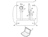
- FIG. 2 is a schematic external view when the measuring device 14 is attached to the analog audio device 15.
- the analog acoustic device 15 in this example is an analog effector that distorts a sound signal.
- the analog audio device 15 includes an input terminal (IN), an output terminal (OUT), a knob 151, and a slider 152.
- the input terminal and the output terminal are analog audio terminals.
- the knob 151 corresponds to the strain intensity parameter (Drive) in this example.
- the slider 152 corresponds to a volume parameter (Vol.).
- the measuring device 14 includes an output terminal (OUT) 101, an input terminal (IN) 102, a servomotor 141, and a servomotor 142.
- the measuring device 14 outputs an analog sound signal to the input terminal of the analog audio device 15 via the output terminal 101.
- the measuring device 14 inputs an analog sound signal from the output terminal of the analog audio device 15 via the input terminal 102.
- the servo motor 141 is attached to the knob 151.
- the servomotor 141 adjusts the strain parameter to an arbitrary value by rotating the knob 151.
- the servomotor 142 is attached to the slider 152 via the rack 143.
- the servomotor 142 includes a pinion gear.
- the servomotor 142 linearly moves the rack 143 via the pinion gear.
- the servomotor 142 adjusts the volume parameter to an arbitrary value by moving the slider 152 via the rack 143.
- the motor 142 may move the slider 152 by converting the rotational motion into a linear motion by the crank mechanism.
- the information processing terminal 11 is connected to the measuring device 14 via a communication line such as USB.
- the information processing terminal 11 transmits a measurement signal to the measurement device 14.
- the information processing terminal 11 inputs a sound signal for measurement to the analog acoustic device 15 via the measurement device 14, and receives the sound signal after signal processing.
- the information processing terminal 11 measures the input / output characteristics of the analog acoustic device 15 based on the sound signal transmitted to the measuring device 14 and the received signal processed sound signal.
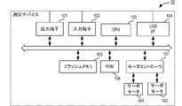
- FIG. 3 is a block diagram showing the configuration of the measuring device 14.
- the measuring device 14 includes an output terminal 101, an input terminal 102, a CPU 103, a USBI / F 104, a flash memory 105, a RAM 106, a motor controller 107, a servomotor 141, and a servomotor 142.
- the CPU 103 is a control unit that controls the operation of the measurement device 14.
- the CPU 103 performs various operations by reading a predetermined program stored in the flash memory 105, which is a storage medium, into the RAM 106 and executing the program.
- the CPU 103 controls the servomotor 141 and the servomotor 142 via the motor controller 107, and adjusts the parameters of the analog audio device 15 to arbitrary values.
- the USBI / F104 is connected to the information processing terminal 11.
- the USBI / F104 receives the first digital sound signal from the information processing terminal 11.
- the first digital sound signal is a sound signal for measurement.
- the sound signal for measurement is, for example, a measurement signal such as white noise, TSP (Time Stretched Pulse), or tone burst. Further, the sound signal for measurement may be a music signal.
- the CPU 103 converts the first digital sound signal into the first analog sound signal and outputs it to the analog audio device 15 via the output terminal 101.
- the CPU 103 receives a second analog sound signal from the analog audio device 15 via the input terminal 102.
- the CPU 103 converts the received second analog sound signal into a second digital sound signal.
- the CPU 103 transmits a second digital sound signal to the information processing terminal 11 via the USB I / F 104.
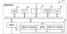
- FIG. 4 is a block diagram showing the configuration of the information processing terminal 11.
- the information processing terminal 11 includes a display 301, a user I / F 302, a USB I / F 303, a flash memory 304, a RAM 305, a communication I / F 306, and a CPU 307.
- the display 301 displays various information to the user.
- the user I / F 302 accepts the user's operation.
- the user I / F 302 may be stacked on the display 301 as a touch panel.
- the USBI / F 303 transmits a first digital sound signal to the measuring device 14. Further, the USB I / F 303 receives a second digital sound signal from the measuring device 14.
- the communication I / F 306 communicates with the server 12 via the network.
- the CPU 307 reads a program stored in the flash memory 304, which is a storage medium, into the RAM 305 to realize a predetermined function. As shown in FIG. 4, the CPU 307 functionally constitutes a standard model acquisition unit 171, a measurement unit 172, and an individual model creation unit 173.
- the standard model acquisition unit 171 acquires the standard model 900 from the server 12.
- the measuring unit 172 measures the input / output characteristics of the analog audio device 15 via the measuring device 14.
- the individual model creation unit 153 creates an individual model that models the input / output characteristics of the analog audio device 15.
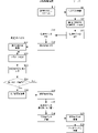
- FIG. 5 is a flowchart showing the operation of the information processing terminal 11, the server 12, and the measuring device 14.
- the user selects the model of the analog acoustic device 15 via the user I / F 302 of the information processing terminal 11 and makes a measurement request (S11).
- the CPU 307 displays a list of amplifier model names on the display 301 by an application program. The user selects the model he / she is using from the displayed list.
- the CPU 307 may display the name of a typical effector such as a distortion, an equalizer, or a compressor on the display 301. The user selects the name of the effector he / she is using from the displayed effector names.
- the server 12 receives the request (S21).
- the server 12 acquires the standard model 900 corresponding to the information indicating the model included in the request (S22).
- the standard model 900 is a model of the standard input / output characteristics of a certain model of analog audio equipment with a digital signal processing block.
- FIG. 6A is a conceptual diagram showing a signal processing block of the standard model 900.
- the standard model 900 has a standard filter block 901 and an adaptive filter block 902.
- the standard filter block 901 and the adaptive filter block 902 are signal processing blocks that simulate the electrical characteristics of an analog circuit (a circuit composed of electronic components such as resistors, diodes, capacitors, vacuum tubes, or coils) with a digital filter, respectively. ..
- FIG. 6A shows only one standard filter block 901 and one adaptive filter block 902 for ease of explanation, and shows an example in which two filter blocks are connected in series.
- the standard model 900 is actually a digital filter circuit having a large number of signal processing blocks and having various connection modes.
- These signal processing blocks are created in advance by a manufacturer of analog audio equipment by simulating the electrical characteristics of an actual analog circuit.
- the standard model may be created by measuring the input / output characteristics (for example, impulse response) of an analog acoustic device under a plurality of measurement conditions. Such a standard model is stored in the database of the server 12.
- the standard filter block 901 is a digital filter that does not depend on changes in parameters such as knobs and sliders of analog audio equipment, and includes, for example, an envelope extraction filter (envelope follower).
- the adaptive filter block 902 is a digital filter whose filter coefficient changes according to a change in a parameter of an analog acoustic device.
- the standard filter block 901 and the adaptive filter block 902 may be a non-linear filter or a linear filter.
- the server 12 transmits the standard model 900 acquired from the database to the information processing terminal 11 (S23).
- the information processing terminal 11 receives the standard model 900 (S12).
- the standard model acquisition unit 171 of the information processing terminal 11 acquires the standard model 900.
- the measurement unit 172 of the information processing terminal 11 transmits a sound signal for measurement to the measurement device 14 to instruct measurement (S13).
- the measuring device 14 Upon receiving the measurement instruction (S31), the measuring device 14 sets the parameters of the analog acoustic device 15 (S32).
- the measuring device 14 sets the values of the knob 151 and the slider 152 when the measuring device 14 is attached to the analog acoustic device 15 as reference values. For example, the user sets the value of the parameter to the value of the most frequently used parameter, attaches the measuring device 14, and instructs the start of measurement via the user I / F 302 of the information processing terminal 11.
- the measuring device 14 inputs a sound signal for measurement to the analog acoustic device 15, and receives the sound signal after signal processing from the analog acoustic device 15 (S33).
- the sound signal for measurement is a measurement signal such as white noise or a music signal.
- measurement is performed for each of a plurality of measurement signals having different levels.
- measurement is performed for each of a plurality of music signals having different contents.
- the measuring device determines whether or not the measurement has been performed for the values of all the parameters of the analog audio device 15 (S34). If the values of all the parameters have not been measured, the process returns to S32 and the parameters are set.
- the measuring device 14 can sequentially set each parameter of the analog audio device 15 to each value of the minimum resolution from the minimum value to the maximum value.
- the relationship between the rotational position of the servomotor 141 and the servomotor 142, the rotational position of the knob 151, and the slide position of the slider 152 is obtained, for example, as follows.
- the manufacturer of the audio equipment has set the server 12 to Drive and Vol. Information such as the minimum value, the maximum value, and the resolution of is registered in the database of the server 12.
- the information processing terminal 11 has Drive and Vol. Information such as the minimum value, the maximum value, and the resolution of is acquired from the server 12.
- the user may input information such as the minimum value, the maximum value, and the resolution of the Drive via the user I / F 302 of the information processing terminal 11.
- the user may take a picture of the picking 151 and the slider 152 by using a camera (not shown) of the information processing terminal 11.
- the information processing terminal 11 can also recognize the maximum value, the minimum value, the resolution, and the current position of the knob 151 and the slider 152 by image processing.
- the measuring device 14 receives information such as a minimum value, a maximum value, and a resolution of each parameter from the information processing terminal 11.
- the measuring device 14 rotates the servomotor 141 left and right, associates the position stopped at the time of clockwise rotation with the minimum value, and associates the position stopped at the time of left rotation with the maximum value.
- the measuring device 14 rotates the servomotor 142 left and right, associates the position stopped at the time of clockwise rotation with the maximum value, and associates the position stopped at the time of left rotation with the minimum value.
- the measuring device 14 associates the resolution information with the rotation angle.
- the measuring device 14 can set each parameter to each value of the minimum resolution from the minimum value to the maximum value by rotating the servo motor 141 and the servo motor 142.
- the user may use a camera (not shown) of the information processing terminal 11 to take a picture of the knob 151 and the slider 152 with the measuring device 14 attached.
- the information processing terminal 11 recognizes the maximum value, the minimum value, the resolution, and the current position of the knob 151 and the slider 152 by image processing.
- the measuring device 14 acquires the maximum value, the minimum value, the resolution, and the position information of the knob 151 and the slider 152 from the information processing terminal 11, the rotation angle of the servomotor 141 and the servomotor 142, and the knob 151 and the slider 152. Find the relationship with the position.
- the parameter values may be changed manually by the user. After the measurement with the value of a certain parameter is completed, the information processing terminal 11 displays a display prompting the display 301 to change the value of the parameter. The user operates the knob 151 or the slider 152 to change the value of the parameter. After that, the user may operate the user I / F 302 of the information processing terminal 11 to give a measurement instruction with the value of the next parameter. Alternatively, the information processing terminal 11 may superimpose a guide of the following parameter values on the images of the knob 151 and the slider 152 taken by the camera (not shown) and display them.
- the measuring device 14 repeats the measurement for each parameter value using a plurality of measurement signals having different volumes or a plurality of musical sound signals of different types.
- the measuring device 14 determines that the measurement has been performed for all the parameter values, the measuring device 14 transmits the sound signal (measurement result) received from the analog audio device 15 to the information processing terminal 11 (S35).
- the measurement result may be sequentially transmitted after performing the measurement using, for example, a certain measurement signal or music signal.
- the information processing terminal 11 receives the measurement result (S14).
- the individual model creation unit 173 of the information processing terminal 11 corrects the standard model based on the measurement result, and creates an individual model modeling the input / output characteristics of the analog audio device 15 (S15).
- the individual model is a model in which the standard model is corrected so as to express the input / output characteristics of the target acoustic device (analog acoustic device 15) for which the measurement was performed.
- the individual model 950 is, for example, a model in which the output of the standard model 900 is corrected by the correction filter block 951.
- the individual model creation unit 173 obtains the difference between the output result when a plurality of sound signals for measurement having different volumes are input to the individual model 950 and the measurement result measured via the measurement device 14.
- a filter coefficient that minimizes the difference is set in the correction filter block 951.
- the correction filter block 951 expresses the frequency characteristic depending on the volume.
- the input / output characteristics of the analog audio device 15 change non-linearly due to changes in parameters.
- the correction filter block 951 is provided for each value of a combination of a plurality of parameters (knob 151 and slider 152) of the analog acoustic device 15. Therefore, the correction filter block 951 is a filter that corrects the difference in input / output characteristics between the standard model 900 and the analog audio device 15.
- the individual model creation unit 153 corrects the output of the standard model 900 by correcting the filter coefficient of the adaptive filter block 902 shown in FIG. 6A, and the corrected standard model 900 may be used as the individual model 950. good. In this case, the correction filter block 951 is unnecessary.
- the individual model creation unit 173 obtains the difference between the output result when a plurality of sound signals for measurement having different volumes are input to the individual model 950 and the result measured via the measurement device 14.
- the individual model creation unit 173 obtains a filter coefficient such that the difference is minimized by a predetermined adaptive algorithm, and corrects the filter coefficient of the adaptive filter block 902.
- the individual model creation unit 173 creates an individual model 950 that expresses the unique sound of the analog audio device 15 owned by the user.
- the information processing terminal 11 transmits the created individual model 950 to the server 12 (S16).
- the server 12 receives the individual model 950 (S24) and registers it in the database (S25).
- the user can download and use the individual model 950 registered in the database of the server 12 at any time.
- the user can use a virtual amplifier or effector having the same input / output characteristics as the analog acoustic device 15 at a necessary place and at a necessary timing without carrying the analog acoustic device 15.
- the standard model and the individual model may be a filter using a predetermined algorithm such as a deep neural network (hereinafter referred to as DNN).
- DNN deep neural network
- the DNN filter is pre-built. For example, a manufacturer of an audio device inputs a large amount of different types of music signals to a standard audio device as a sound signal for measurement, and uses the output signal as a correct answer to deeply learn the input / output characteristics of the audio device.
- the audio equipment manufacturer first fixes the parameters, inputs a large amount of different types of music signals, and deep-learns the input / output characteristics of the audio equipment. After that, when the value of the parameter is changed, the manufacturer of the audio equipment performs limited deep learning that limits the learning of the filtered block that does not affect the change of the parameter.
- the manufacturer of audio equipment creates a standard model by DNN in this way.
- the individual model creation unit 173 trains the correction filter block 951 that corrects the output of the standard model 900.
- the correction filter block 951 is also a DNN filter.
- the individual model creation unit 173 creates an individual model 950 by deep learning the correction filter block 951 by DNN.
- the individual model creation unit 173 obtains a difference between the output result when a plurality of types of music signals are input to the individual model 950 and the measurement result measured via the measurement device 14, so that the difference is minimized.
- DNN it is preferable to input a large amount of music signals of different types and learn the measurement result as a correct answer.
- the learning of the correction filter block 951 is a process of correcting the standard model 900 to the individual model 950, the calculation load is significantly lower than the learning when the standard model 900 is created.
- the individual model creation unit 173 may correct the output of the standard model 900 by deep learning the adaptive filter block 902 shown in FIG. 6A again, and use the corrected standard model 900 as the individual model 950. .. In this case, limited learning that limits learning other than the adaptive filter block 902 related to the parameters of the knob 151 and the slider 152 is performed.
- the individual model 950 may be created by deep learning.
- the individual model creation unit 173 creates an individual model 950 by correcting the standard model 900 previously created by the manufacturer of the acoustic device by the first deep learning by the second deep learning with restrictions related to the parameters. Is preferable.
- the simulation system 1 of the present embodiment can reduce the calculation load when creating the individual model 950.
- the information processing terminal 11 communicates with the server 12, acquires a standard model, and creates an individual model. That is, in the present embodiment, the information processing terminal 11 is shown as an example of the simulation device of the audio equipment.
- the measuring device 14 may have a communication function, communicate with the server 12, acquire a standard model, and create an individual model. In this case, the measuring device 14 also functions as a simulation device for audio equipment.
- the server 12 may transmit a sound signal for measurement to the measurement device 14, receive the measurement result, and create an individual model based on the measurement result. In this case, the server 12 functions as a simulation device for audio equipment.
Landscapes
- Physics & Mathematics (AREA)
- Engineering & Computer Science (AREA)
- Acoustics & Sound (AREA)
- Multimedia (AREA)
- Nonlinear Science (AREA)
- Measurement Of Mechanical Vibrations Or Ultrasonic Waves (AREA)
- Measurement Of Velocity Or Position Using Acoustic Or Ultrasonic Waves (AREA)
Abstract
Priority Applications (4)
| Application Number | Priority Date | Filing Date | Title |
|---|---|---|---|
| JP2022568015A JP7593415B2 (ja) | 2020-12-11 | 2020-12-11 | 音響機器のシミュレート方法、音響機器のシミュレート装置、および音響機器のシミュレートシステム |
| PCT/JP2020/046308 WO2022123775A1 (fr) | 2020-12-11 | 2020-12-11 | Procédé, dispositif et système de simulation pour appareil acoustique |
| CN202080107591.6A CN116670752B (zh) | 2020-12-11 | 2020-12-11 | 音响机器的仿真方法、音响机器的仿真装置以及音响机器的仿真系统 |
| US18/329,950 US20230317043A1 (en) | 2020-12-11 | 2023-06-06 | Audio device simulation method, audio device simulator, and audio device simulation system |
Applications Claiming Priority (1)
| Application Number | Priority Date | Filing Date | Title |
|---|---|---|---|
| PCT/JP2020/046308 WO2022123775A1 (fr) | 2020-12-11 | 2020-12-11 | Procédé, dispositif et système de simulation pour appareil acoustique |
Related Child Applications (1)
| Application Number | Title | Priority Date | Filing Date |
|---|---|---|---|
| US18/329,950 Continuation US20230317043A1 (en) | 2020-12-11 | 2023-06-06 | Audio device simulation method, audio device simulator, and audio device simulation system |
Publications (1)
| Publication Number | Publication Date |
|---|---|
| WO2022123775A1 true WO2022123775A1 (fr) | 2022-06-16 |
Family
ID=81974279
Family Applications (1)
| Application Number | Title | Priority Date | Filing Date |
|---|---|---|---|
| PCT/JP2020/046308 Ceased WO2022123775A1 (fr) | 2020-12-11 | 2020-12-11 | Procédé, dispositif et système de simulation pour appareil acoustique |
Country Status (4)
| Country | Link |
|---|---|
| US (1) | US20230317043A1 (fr) |
| JP (1) | JP7593415B2 (fr) |
| CN (1) | CN116670752B (fr) |
| WO (1) | WO2022123775A1 (fr) |
Citations (2)
| Publication number | Priority date | Publication date | Assignee | Title |
|---|---|---|---|---|
| JP2016105246A (ja) * | 2014-12-01 | 2016-06-09 | ヤマハ株式会社 | 操作装置 |
| WO2020035255A1 (fr) * | 2018-08-13 | 2020-02-20 | Viscount International S.P.A. | Système de génération de sons synthétisés dans des instruments de musique |
Family Cites Families (6)
| Publication number | Priority date | Publication date | Assignee | Title |
|---|---|---|---|---|
| JPH01314097A (ja) * | 1988-06-13 | 1989-12-19 | Mazda Motor Corp | 車両用オーディオ装置 |
| CN1838752A (zh) * | 2005-03-23 | 2006-09-27 | 乐金电子(沈阳)有限公司 | 图像显示设备的音响补正装置及方法 |
| JP2010226332A (ja) * | 2009-03-23 | 2010-10-07 | Sony Ericsson Mobile Communications Ab | 携帯端末装置およびサーバ |
| JP2012182553A (ja) * | 2011-02-28 | 2012-09-20 | Toshiba Corp | 再生装置、オーディオデータ補正装置、および再生方法 |
| WO2017203677A1 (fr) * | 2016-05-27 | 2017-11-30 | ヤマハ株式会社 | Dispositif de traitement de signal audio et procédé de détermination de paramètre sonore |
| JP7143863B2 (ja) * | 2018-02-14 | 2022-09-29 | ヤマハ株式会社 | 音響パラメータ調整装置、音響パラメータ調整方法および音響パラメータ調整プログラム |
-
2020
- 2020-12-11 JP JP2022568015A patent/JP7593415B2/ja active Active
- 2020-12-11 CN CN202080107591.6A patent/CN116670752B/zh active Active
- 2020-12-11 WO PCT/JP2020/046308 patent/WO2022123775A1/fr not_active Ceased
-
2023
- 2023-06-06 US US18/329,950 patent/US20230317043A1/en active Pending
Patent Citations (2)
| Publication number | Priority date | Publication date | Assignee | Title |
|---|---|---|---|---|
| JP2016105246A (ja) * | 2014-12-01 | 2016-06-09 | ヤマハ株式会社 | 操作装置 |
| WO2020035255A1 (fr) * | 2018-08-13 | 2020-02-20 | Viscount International S.P.A. | Système de génération de sons synthétisés dans des instruments de musique |
Non-Patent Citations (1)
| Title |
|---|
| BENSA, JULIEN ET AL.: "Parameter fitting for piano sound synthesis by physical modeling", THE JOURNAL OF THE ACOUSTIC SOCIETY OF AMERICA, vol. 118, no. 1, 28 June 2005 (2005-06-28), pages 495 - 504, XP012073194, DOI: 10.1121/1.1929230 * |
Also Published As
| Publication number | Publication date |
|---|---|
| CN116670752B (zh) | 2025-05-30 |
| JP7593415B2 (ja) | 2024-12-03 |
| CN116670752A (zh) | 2023-08-29 |
| US20230317043A1 (en) | 2023-10-05 |
| JPWO2022123775A1 (fr) | 2022-06-16 |
Similar Documents
| Publication | Publication Date | Title |
|---|---|---|
| JPH04501198A (ja) | カラー・デジタル・ハードコピー装置を較正する方法とその装置 | |
| JP2016524176A (ja) | ガンマ抵抗調整装置、駆動回路及び表示装置 | |
| US10395630B1 (en) | Touchless knob and method of use | |
| CN103826112A (zh) | 投影装置及投影状态调整方法 | |
| US20220261209A1 (en) | Robotic system for controlling audio systems | |
| JP7201031B2 (ja) | 電子機器、プログラム、グラフ画像生成システムおよび画像生成方法 | |
| JP7593415B2 (ja) | 音響機器のシミュレート方法、音響機器のシミュレート装置、および音響機器のシミュレートシステム | |
| JPH07114519B2 (ja) | 電気音響変換器の再生誤差補償装置 | |
| WO2017179219A1 (fr) | Dispositif d'attaque de haut-parleur, dispositif de haut-parleur et programme | |
| CN108924447A (zh) | 一种音量调节方法及设备 | |
| US9940915B2 (en) | Effect unit based on dynamic circuit modeling method that can change effect wirelessly | |
| JP2019203912A (ja) | 模倣音信号生成装置、電子楽器、非線形システム同定方法 | |
| JPWO2022123775A5 (ja) | 音響機器のシミュレート方法、音響機器のシミュレート装置、および音響機器のシミュレートシステム | |
| JP4209266B2 (ja) | リアルタイムシミュレーション装置およびリアルタイムシミュレーション方法 | |
| WO2021251222A1 (fr) | Dispositif d'apprentissage, dispositif de présentation et procédé d'acquisition de technique | |
| KR20120133860A (ko) | 전자도서관을 이용한 학습 서비스 시스템 및 방법 | |
| CN118778669B (zh) | 一种用于飞拍检测的运动规划方法 | |
| CN114267228B (zh) | 用于电子实验箱的模拟电路、检测电路及电路检查方法 | |
| CN109861523A (zh) | 恒流模块串联输出的均压控制方法、装置及芯片 | |
| EP4485977A1 (fr) | Détermination de position de haut-parleur sur la base d'une réponse impulsionnelle | |
| JP2006064973A (ja) | 制御システム | |
| EP1722244A1 (fr) | Dispositif et méthode pour la simulation de pannes | |
| WO2019188154A1 (fr) | Dispositif d'entraînement de moteur | |
| JPS6238340Y2 (fr) | ||
| CN108322857A (zh) | 一种信号处理装置 |
Legal Events
| Date | Code | Title | Description |
|---|---|---|---|
| 121 | Ep: the epo has been informed by wipo that ep was designated in this application |
Ref document number: 20965157 Country of ref document: EP Kind code of ref document: A1 |
|
| WWE | Wipo information: entry into national phase |
Ref document number: 202080107591.6 Country of ref document: CN |
|
| ENP | Entry into the national phase |
Ref document number: 2022568015 Country of ref document: JP Kind code of ref document: A |
|
| NENP | Non-entry into the national phase |
Ref country code: DE |
|
| 122 | Ep: pct application non-entry in european phase |
Ref document number: 20965157 Country of ref document: EP Kind code of ref document: A1 |
|
| WWG | Wipo information: grant in national office |
Ref document number: 202080107591.6 Country of ref document: CN |