WO2022123786A1 - 信頼度推定装置、位置推定装置、及び信頼度推定方法 - Google Patents
信頼度推定装置、位置推定装置、及び信頼度推定方法 Download PDFInfo
- Publication number
- WO2022123786A1 WO2022123786A1 PCT/JP2020/046360 JP2020046360W WO2022123786A1 WO 2022123786 A1 WO2022123786 A1 WO 2022123786A1 JP 2020046360 W JP2020046360 W JP 2020046360W WO 2022123786 A1 WO2022123786 A1 WO 2022123786A1
- Authority
- WO
- WIPO (PCT)
- Prior art keywords
- reliability
- feature
- calculation unit
- feature amount
- camera image
- Prior art date
- Legal status (The legal status is an assumption and is not a legal conclusion. Google has not performed a legal analysis and makes no representation as to the accuracy of the status listed.)
- Ceased
Links
Images


Classifications
-
- G—PHYSICS
- G06—COMPUTING OR CALCULATING; COUNTING
- G06T—IMAGE DATA PROCESSING OR GENERATION, IN GENERAL
- G06T7/00—Image analysis
- G06T7/70—Determining position or orientation of objects or cameras
- G06T7/73—Determining position or orientation of objects or cameras using feature-based methods
-
- G—PHYSICS
- G06—COMPUTING OR CALCULATING; COUNTING
- G06T—IMAGE DATA PROCESSING OR GENERATION, IN GENERAL
- G06T7/00—Image analysis
- G06T7/70—Determining position or orientation of objects or cameras
- G06T7/77—Determining position or orientation of objects or cameras using statistical methods
-
- G—PHYSICS
- G06—COMPUTING OR CALCULATING; COUNTING
- G06T—IMAGE DATA PROCESSING OR GENERATION, IN GENERAL
- G06T2207/00—Indexing scheme for image analysis or image enhancement
- G06T2207/20—Special algorithmic details
- G06T2207/20076—Probabilistic image processing
-
- G—PHYSICS
- G06—COMPUTING OR CALCULATING; COUNTING
- G06T—IMAGE DATA PROCESSING OR GENERATION, IN GENERAL
- G06T2207/00—Indexing scheme for image analysis or image enhancement
- G06T2207/20—Special algorithmic details
- G06T2207/20084—Artificial neural networks [ANN]
Definitions
- This disclosure relates to a reliability estimation device.
- a three-dimensional position estimation algorithm for estimating the three-dimensional position of an object based on an image has been developed (in the present specification, the three-dimensional position of an object is synonymous with a three-dimensional posture).
- the three-dimensional position of an object is synonymous with a three-dimensional posture.
- Non-Patent Document 1 by applying a neural network model to a camera image obtained by a monocular camera taking an object, the object in the camera image is recognized and the position of a feature point of the object is recognized.
- a three-dimensional position estimation method for estimating the three-dimensional position of an object based on the estimated position of the feature point is described.
- the position of the object estimated by such a three-dimensional position estimation method (for example, the position of the feature point of the object or the three-dimensional position of the object) is referred to as an estimated position.
- the reliability of the estimated position is determined by using the same neural network model as the machine learning model used to estimate the estimated position. It may be calculated and the calculated reliability may be used to evaluate the estimated position.
- the present disclosure has been made to solve the above-mentioned problems, and an object of the present disclosure is to provide a technique for improving the reliability of the estimated position itself.
- the reliability estimation device is a reliability estimation device that estimates the reliability of the estimated position of the object estimated based on the camera image, and is used for feature point information regarding a plurality of feature points of the object in the camera image. Based on this, it includes a feature amount calculation unit that calculates the feature amount of the object, and a reliability calculation unit that calculates the reliability based on the feature amount calculated by the feature amount calculation unit.
- the reliability of the estimated position itself can be improved.
- FIG. 4A is a block diagram showing a hardware configuration that realizes the function of the position estimation device according to the first embodiment.
- FIG. 4B is a block diagram showing a hardware configuration for executing software that realizes the function of the position estimation device according to the first embodiment.
- FIG. 1 is a block diagram showing a configuration of a position estimation system 100 according to a first embodiment.
- the position estimation system 100 includes a position estimation device 1, N cameras 2 (N is a positive integer), and a storage device 3.
- the position estimation device 1 includes a camera selection unit 40, a feature point estimation unit 10, a reliability estimation device 20, and a position calculation unit 30.
- the reliability estimation device 20 includes a feature amount calculation unit 21 and a reliability calculation unit 22.
- the N cameras 2 are composed of each camera 2 from the first camera 2 to the Nth camera 2. Each of the N cameras 2 acquires a camera image (camera images D11 to D1N) by photographing an object. Each of the N cameras 2 outputs the acquired camera image to the camera selection unit 40 of the position estimation device 1.
- the camera selection unit 40 selects at least one camera image D2 from a plurality of camera images. More specifically, in the first embodiment, the camera selection unit 40 selects at least one camera image D2 from the plurality of camera images D11 to D1N acquired by the N cameras 2. The detailed configuration of the camera selection unit 40 will be described later.
- the camera selection unit 40 outputs the selected camera image D2 to the feature point estimation unit 10 and the feature amount calculation unit 21, respectively.
- the feature point estimation unit 10 estimates feature point information regarding a plurality of feature points of an object based on a camera image. More specifically, in the first embodiment, the feature point estimation unit 10 estimates the feature point information based on the camera image D2 selected by the camera selection unit 40.
- the storage device 3 stores PVNet, which is a convolutional neural network model for object position detection.
- the feature point estimation unit 10 applies PVNet stored in the storage device 3 to the camera image D2 selected by the camera selection unit 40, so that each estimated position D3 of a plurality of feature points can be used as feature point information.
- the dispersion D4 of the candidate point group of the feature points, and the object area D5 which is the area occupied by the object in the camera image are estimated.
- the feature point estimation unit 10 outputs each estimated position D3 of the estimated plurality of feature points to the position calculation unit 30. Further, the feature point estimation unit 10 outputs each estimated position D3 of the estimated plurality of feature points, the variance D4 of the candidate point group of the feature points, and the object region D5 to the feature amount calculation unit 21.
- the feature amount calculation unit 21 calculates the feature amount of the object based on the feature point information regarding a plurality of feature points of the object in the camera image. More specifically, in the first embodiment, the feature amount calculation unit 21 calculates the feature amount of the object based on the feature point information estimated by the feature point estimation unit 10.
- the feature amount calculation unit 21 includes m feature amount calculation units from the first feature amount calculation unit 201 to the mth feature amount calculation unit 20 m.
- the first feature amount calculation unit 201 calculates the feature amount D61 of the object based on the variance D4 of the candidate point cloud of the feature points estimated by the feature point estimation unit 10.
- the feature amount D61 calculated by the first feature amount calculation unit 201 is a feature amount proportional to the reciprocal of the variance D4 of the candidate point group of the feature points.
- the feature amount D61 calculated by the first feature amount calculation unit 201 is a feature amount that is inversely proportional to the variance D4 of the candidate point cloud of the feature points.
- the first feature amount calculation unit 201 outputs the calculated feature amount D61 to the reliability calculation unit 22.
- the second feature amount calculation unit 202 inputs a region composed of a plurality of feature points and an object region based on the estimated positions D3 and the object region D5 of the plurality of feature points estimated by the feature point estimation unit 10.
- the feature amount D62 which is a function to be taken is calculated. More specifically, in the first embodiment, the second feature amount calculation unit 202 has a plurality of feature points based on the estimated positions D3 and the object area D5 of the plurality of feature points estimated by the feature point estimation unit 10.
- the area ratio between the convex plane composed of and the object area is calculated, and the feature amount proportional to the inverse number of the calculated area ratio or the feature amount D62 proportional to the inverse number of the difference between the calculated area ratio and 1 is calculated. ..
- the "convex plane composed of a plurality of feature points” is, for example, the largest convex plane in which a plurality of feature points are stretched, or the smallest convex plane containing all the plurality of feature points.
- the second feature amount calculation unit 202 outputs the calculated feature amount D62 to the reliability calculation unit 22.
- Each feature amount calculation unit from the third feature amount calculation unit to the mth feature amount calculation unit 20m includes a camera image D2 selected by the camera selection unit 40 and a plurality of feature points estimated by the feature point estimation unit 10. Based on the information of at least one of each estimated position D3, the dispersion D4 of the candidate point group of the feature points, and the object area D5, the feature amount (feature amount D63 to D6m) that can be calculated from the at least one information is calculated. do.
- Each feature amount calculation unit from the third feature amount calculation unit (not shown) to the mth feature amount calculation unit 20 m outputs the calculated feature amount to the reliability calculation unit 22.
- the reliability calculation unit 22 calculates the reliability of the estimated position of the object based on the feature amount calculated by the feature amount calculation unit 21. More specifically, in the first embodiment, the reliability calculation unit 22 correlates with the estimation error of the estimated position of the object based on the feature amounts (feature amounts D61 to D6m) calculated by the feature amount calculation unit 21.
- the reliability D7 (for example, the reliability D7 having a positive correlation with the estimation error) is calculated.
- the storage device 3 stores a neural network model that calculates the reliability from the feature amount.
- the reliability calculation unit 22 applies the neural network model stored in the storage device 3 to the feature amounts (feature amounts D61 to D6m) calculated by the feature amount calculation unit 21, and thereby, the estimated position of the object.
- the reliability D7 which is inversely proportional to the estimation error of, is calculated.
- the reliability calculation unit 22 outputs the calculated reliability D7 to the outside of the camera selection unit 40 and the position estimation device 1, respectively.
- the camera selection unit 40 described above selects at least one camera image D2 from the N camera images D11 to D1N based on the reliability D7 calculated by the reliability calculation unit 22.
- the camera selection unit 40 outputs the camera image D2 selected based on the reliability D7 to the feature point estimation unit 10 and the feature amount calculation unit 21, respectively.
- the position calculation unit 30 calculates the estimated position D8 of the object based on the feature point information estimated by the feature point estimation unit 10. More specifically, in the first embodiment, the storage device 3 stores the position of the feature point of the object. The position calculation unit 30 solves the PnP problem by solving the PnP problem based on each estimated position D3 of the plurality of feature points estimated by the feature point estimation unit 10 and the feature point position of the object stored in the storage device 3. The estimated position D8 of is calculated.
- An example of the estimated position D8 calculated by the position calculation unit 30 is a three-dimensional position (three-dimensional posture) of an object.
- the position calculation unit 30 outputs the calculated estimated position D8 to the outside of the position estimation device 1.
- the reliability D7 output by the reliability calculation unit 22 to the outside of the position estimation device 1 is used, for example, for the evaluation of the estimated position D8 output to the outside of the position estimation device 1 by the position calculation unit 30.
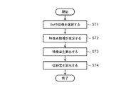
- FIG. 2 is a flowchart showing a reliability estimation method by the position estimation device 1 according to the first embodiment. Before each step described below, it is assumed that each of the N cameras 2 acquires a camera image by photographing an object and outputs the acquired camera image to the camera selection unit 40.
- the camera selection unit 40 selects at least one camera image D2 from a plurality of camera images (step ST1).
- the camera selection unit 40 outputs the selected camera image D2 to the feature point estimation unit 10 and the feature amount calculation unit 21, respectively.
- the feature point estimation unit 10 uses the camera image D2 selected by the camera selection unit 40 as feature point information such as each estimated position D3 of a plurality of feature points, a dispersion D4 of a candidate point group of the feature points, and a feature point cloud.
- the object region D5 is estimated (step ST2).
- the feature point estimation unit 10 outputs each estimated position D3 of the estimated plurality of feature points, the variance D4 of the candidate point group of the feature points, and the object region D5 to the feature amount calculation unit 21.
- the feature amount calculation unit 21 includes a camera image D2 selected by the camera selection unit 40, each estimated position D3 of a plurality of feature points estimated by the feature point estimation unit 10, a dispersion D4 of a group of candidate points of the feature points, and an object.
- the feature amounts D61 to D6m of the object are calculated in the area D5 based on the information of at least one of the feature amount calculation units 21 (step ST3).
- the feature amount calculation unit 21 outputs the calculated feature amounts D61 to D6m to the reliability calculation unit 22.
- FIG. 3 is a flowchart showing details of the feature amount calculation method in step ST3.
- the first feature amount calculation unit 201 is based on the variance D4 of the candidate point group of the feature points estimated by the feature point estimation unit 10, and the feature amount of the object proportional to the reciprocal of the variance D4.
- Calculate D61 step ST31).
- the first feature amount calculation unit 201 outputs the calculated feature amount D61 to the reliability calculation unit 22.
- Each feature amount calculation unit from the third feature amount calculation unit to the mth feature amount calculation unit 20m is a camera image D2 selected by the camera selection unit 40 and each of a plurality of feature points estimated by the feature point estimation unit 10.
- the other feature quantities D63 to D6m are calculated based on the information of at least one of the estimated position D3, the dispersion D4 of the candidate point group of the feature points, and the object region D5 (step ST33).
- Each feature amount calculation unit from the third feature amount calculation unit to the mth feature amount calculation unit 20m outputs the calculated feature amount to the reliability calculation unit 22.
- step ST1 a specific example of the camera selection method (step ST1) in the reliability estimation method by the position estimation device 1 according to the first embodiment will be described in detail. It is assumed that the step of step ST1 described below is performed again after performing a series of steps from step ST1 to step ST4 once or more.
- the position estimation device 1 returns to the step of step ST1 described above, and the camera selection unit 40 is a camera calculated by the reliability calculation unit 22 when the reliability calculation unit 22 calculates the reliability for each camera image.
- At least one camera image D2 is selected from the N camera images D11 to D1N based on the maximum reliability of the reliability of each image. More specifically, for example, when the reliability calculation unit 22 calculates the reliability for each camera image, the camera selection unit 40 has the maximum reliability of the reliability for each camera image calculated by the reliability calculation unit 22.
- the camera image D2 taken by the camera 2 corresponding to the degree is selected.
- the functions of the camera selection unit 40, the feature point estimation unit 10, the feature amount calculation unit 21 and the reliability calculation unit 22 of the reliability estimation device 20, and the position calculation unit 30 in the position estimation device 1 are realized by separate processing circuits. Alternatively, these functions may be integrated into one processing circuit.
- the reliability estimation device 20 is a reliability estimation device 20 that estimates the reliability of the estimated position of the object estimated based on the camera image, and is the reliability estimation device 20 of the object in the camera image.
- the reliability of the estimated position of the object is calculated based on the feature amount calculation unit 21 that calculates the feature amount of the object based on the feature point information about a plurality of feature points and the feature amount calculated by the feature amount calculation unit 21.
- a reliability calculation unit 22 is provided.
- the reliability estimation device 20 when gripping an object with a robot arm, it is necessary to detect the position of the object. Therefore, when an image taken by a monocular camera or the like attached to the arm is applied as the above-mentioned camera image to the reliability estimation device 20 according to the first embodiment, an image in which position estimation is difficult due to poor shooting conditions is input. However, the above-mentioned reliability with high reliability can be calculated, and the estimated position can be evaluated based on the reliability. Therefore, stable robot control can be realized.
- the reliability estimation device can be used as a position estimation device because the reliability of the reliability of the estimated position itself can be improved.
Landscapes
- Engineering & Computer Science (AREA)
- Physics & Mathematics (AREA)
- Computer Vision & Pattern Recognition (AREA)
- General Physics & Mathematics (AREA)
- Theoretical Computer Science (AREA)
- Life Sciences & Earth Sciences (AREA)
- Bioinformatics & Cheminformatics (AREA)
- Bioinformatics & Computational Biology (AREA)
- Evolutionary Biology (AREA)
- Probability & Statistics with Applications (AREA)
- Length Measuring Devices By Optical Means (AREA)
- Image Analysis (AREA)
Abstract
Description
本開示は、上記のような問題点を解決するためになされたものであり、推定位置の信頼度自体の信頼性を向上させる技術を提供することを目的とする。
実施の形態1.
図1は、実施の形態1に係る位置推定システム100の構成を示すブロック図である。図1が示すように、位置推定システム100は、位置推定装置1、N個のカメラ2(Nは正の整数)、及び記憶装置3を含む。位置推定装置1は、カメラ選択部40、特徴点推定部10、信頼度推定装置20、及び位置算出部30を備えている。信頼度推定装置20は、特徴量算出部21、及び信頼度算出部22を備えている。
第1の特徴量算出部201は、特徴点推定部10が推定した特徴点の候補点群の分散D4に基づいて、物体の特徴量D61を算出する。なお、実施の形態1では、第1の特徴量算出部201が算出する特徴量D61は、特徴点の候補点群の分散D4の逆数に比例する特徴量である。換言すれば、第1の特徴量算出部201が算出する特徴量D61は、特徴点の候補点群の分散D4に逆比例する特徴量である。第1の特徴量算出部201は、算出した特徴量D61を信頼度算出部22に出力する。
なお、信頼度算出部22が位置推定装置1の外部に出力した信頼度D7は、例えば、位置算出部30が位置推定装置1の外部に出力した推定位置D8の評価に用いられる。
図3が示すように、第1の特徴量算出部201は、特徴点推定部10が推定した特徴点の候補点群の分散D4に基づいて、当該分散D4の逆数に比例する物体の特徴量D61を算出する(ステップST31)。第1の特徴量算出部201は、算出した特徴量D61を信頼度算出部22に出力する。
次に、上述のステップST4において、信頼度算出部22は、特徴量算出部21がカメラ画像毎に算出した特徴量に基づいて、カメラ画像毎に、物体の推定位置の信頼度を算出する。
なお、ソフトウェア又はファームウェアは、プログラムとして記述されてメモリ52に記憶される。
このように、処理回路は、ハードウェア、ソフトウェア、ファームウェア又はこれらの組み合わせにより上記機能のそれぞれを実現することができる。
上記の構成によれば、特徴点の候補点群の分散から算出した物体の特徴量に基づいて物体の推定位置の信頼度を算出する。これにより、推定位置の信頼度自体の信頼性を好適に向上させることができる。
上記の構成によれば、分散の逆数に比例する特徴量に基づいて物体の推定位置の信頼度を算出する。これにより、推定位置の信頼度自体の信頼性を好適に向上させることができる。
上記の構成によれば、物体の推定位置の推定誤差に相関する信頼度を用いて、物体の推定位置を評価することができる。
上記の構成によれば、実施の形態1に係る信頼度推定装置20が奏する上述の効果と同様の効果を奏する。
なお、実施の形態の任意の構成要素の変形、もしくは実施の形態の任意の構成要素の省略が可能である。
Claims (10)
- カメラ画像に基づいて推定された物体の推定位置の信頼度を推定する信頼度推定装置であって、
前記カメラ画像における前記物体の複数の特徴点に関する特徴点情報に基づいて、前記物体の特徴量を算出する特徴量算出部と、
前記特徴量算出部が算出した特徴量に基づいて、前記信頼度を算出する信頼度算出部と、を備えていることを特徴とする、信頼度推定装置。 - 前記特徴点情報は、前記特徴点の候補点群の分散を含み、
前記特徴量算出部は、前記特徴点の候補点群の分散に基づいて、前記特徴量を算出することを特徴とする、請求項1に記載の信頼度推定装置。 - 前記特徴量算出部は、前記分散の逆数に比例する特徴量を算出することを特徴とする、請求項2に記載の信頼度推定装置。
- 前記特徴点情報は、複数の特徴点の各推定位置、及び前記カメラ画像において前記物体が占める領域である物体領域を含み、
前記特徴量算出部は、前記複数の特徴点の各推定位置、及び前記物体領域に基づいて、前記複数の特徴点から構成される領域と当該物体領域とを入力にとる関数となる特徴量を算出することを特徴とする、請求項1に記載の信頼度推定装置。 - 前記特徴量算出部は、前記特徴量を複数算出し、
前記信頼度算出部は、前記特徴量算出部が複数算出した特徴量に基づいて、前記物体の推定位置の推定誤差に相関する信頼度を算出することを特徴とする、請求項1に記載の信頼度推定装置。 - 請求項1に記載の信頼度推定装置と、
前記カメラ画像に基づいて、前記特徴点情報を推定する特徴点推定部と、
前記特徴点推定部が推定した特徴点情報に基づいて、前記物体の推定位置を算出する位置算出部と、を備え、
前記特徴量算出部は、前記特徴点推定部が推定した特徴点情報に基づいて、前記特徴量を算出することを特徴とする、位置推定装置。 - 前記信頼度算出部が算出した信頼度に基づいて、複数のカメラ画像のうちから少なくとも1つのカメラ画像を選択するカメラ選択部をさらに備え、
前記特徴点推定部は、前記カメラ選択部が選択したカメラ画像に基づいて、前記特徴点情報を推定することを特徴とする、請求項6に記載の位置推定装置。 - 前記カメラ選択部は、
前記信頼度算出部が算出した信頼度が閾値以上の場合、前回選択したカメラ画像に対応するカメラからのカメラ画像を選択し、
前記信頼度算出部が算出した信頼度が閾値未満の場合、前記複数のカメラ画像を全て選択することを特徴とする、請求項7に記載の位置推定装置。 - 前記特徴点推定部は、前記カメラ選択部が前記複数のカメラ画像を全て選択した場合、カメラ画像毎に、前記特徴点情報を推定し、
前記特徴量算出部は、前記特徴点推定部がカメラ画像毎に推定した特徴点情報に基づいて、カメラ画像毎に、前記特徴量を算出し、
前記信頼度算出部は、前記特徴量算出部がカメラ画像毎に算出した特徴量に基づいて、カメラ画像毎に、前記信頼度を算出し、
前記カメラ選択部は、前記信頼度算出部がカメラ画像毎に前記信頼度を算出した場合、前記信頼度算出部が算出したカメラ画像毎の信頼度のうちの最大の信頼度に基づいて、前記複数のカメラ画像のうちから少なくとも1つのカメラ画像を選択することを特徴とする、請求項8に記載の位置推定装置。 - カメラ画像に基づいて推定された物体の推定位置の信頼度を推定する信頼度推定方法であって、
前記カメラ画像における前記物体の複数の特徴点に関する特徴点情報に基づいて、前記物体の特徴量を算出する特徴量算出ステップと、
前記特徴量算出ステップで算出した特徴量に基づいて、前記信頼度を算出する信頼度算出ステップと、を含むことを特徴とする、信頼度推定方法。
Priority Applications (5)
| Application Number | Priority Date | Filing Date | Title |
|---|---|---|---|
| DE112020007687.3T DE112020007687T5 (de) | 2020-12-11 | 2020-12-11 | Zuverlässigkeitsgrad-ermittlungseinrichtung, position-ermittlungseinrichtung und zuverlässigkeitsgrad-ermittlungsverfahren |
| JP2022568023A JP7221469B2 (ja) | 2020-12-11 | 2020-12-11 | 信頼度推定装置、位置推定装置、及び信頼度推定方法 |
| CN202080107744.7A CN116547714B (zh) | 2020-12-11 | 2020-12-11 | 可靠度推定装置、位置推定装置以及可靠度推定方法 |
| PCT/JP2020/046360 WO2022123786A1 (ja) | 2020-12-11 | 2020-12-11 | 信頼度推定装置、位置推定装置、及び信頼度推定方法 |
| TW110114658A TW202232433A (zh) | 2020-12-11 | 2021-04-23 | 可靠度推定裝置、位置推定裝置及可靠度推定方法 |
Applications Claiming Priority (1)
| Application Number | Priority Date | Filing Date | Title |
|---|---|---|---|
| PCT/JP2020/046360 WO2022123786A1 (ja) | 2020-12-11 | 2020-12-11 | 信頼度推定装置、位置推定装置、及び信頼度推定方法 |
Publications (1)
| Publication Number | Publication Date |
|---|---|
| WO2022123786A1 true WO2022123786A1 (ja) | 2022-06-16 |
Family
ID=81974299
Family Applications (1)
| Application Number | Title | Priority Date | Filing Date |
|---|---|---|---|
| PCT/JP2020/046360 Ceased WO2022123786A1 (ja) | 2020-12-11 | 2020-12-11 | 信頼度推定装置、位置推定装置、及び信頼度推定方法 |
Country Status (5)
| Country | Link |
|---|---|
| JP (1) | JP7221469B2 (ja) |
| CN (1) | CN116547714B (ja) |
| DE (1) | DE112020007687T5 (ja) |
| TW (1) | TW202232433A (ja) |
| WO (1) | WO2022123786A1 (ja) |
Cited By (1)
| Publication number | Priority date | Publication date | Assignee | Title |
|---|---|---|---|---|
| WO2024127824A1 (ja) * | 2022-12-12 | 2024-06-20 | ソニーグループ株式会社 | 情報処理装置、情報処理方法、およびプログラム |
Citations (2)
| Publication number | Priority date | Publication date | Assignee | Title |
|---|---|---|---|---|
| JP2008186246A (ja) * | 2007-01-30 | 2008-08-14 | Aisin Seiki Co Ltd | 移動物体認識装置 |
| JP2008310775A (ja) * | 2007-06-18 | 2008-12-25 | Canon Inc | 表情認識装置及び方法、並びに撮像装置 |
Family Cites Families (4)
| Publication number | Priority date | Publication date | Assignee | Title |
|---|---|---|---|---|
| JP5057183B2 (ja) * | 2010-03-31 | 2012-10-24 | アイシン・エィ・ダブリュ株式会社 | 風景マッチング用参照データ生成システム及び位置測位システム |
| US9374571B2 (en) * | 2011-10-11 | 2016-06-21 | Panasonic Intellectual Property Management Co., Ltd. | Image processing device, imaging device, and image processing method |
| JP6694234B2 (ja) * | 2015-01-23 | 2020-05-13 | シャープ株式会社 | 距離測定装置 |
| JP6710190B2 (ja) * | 2017-09-29 | 2020-06-17 | クラリオン株式会社 | 区画線認識装置 |
-
2020
- 2020-12-11 WO PCT/JP2020/046360 patent/WO2022123786A1/ja not_active Ceased
- 2020-12-11 JP JP2022568023A patent/JP7221469B2/ja active Active
- 2020-12-11 DE DE112020007687.3T patent/DE112020007687T5/de active Pending
- 2020-12-11 CN CN202080107744.7A patent/CN116547714B/zh active Active
-
2021
- 2021-04-23 TW TW110114658A patent/TW202232433A/zh unknown
Patent Citations (2)
| Publication number | Priority date | Publication date | Assignee | Title |
|---|---|---|---|---|
| JP2008186246A (ja) * | 2007-01-30 | 2008-08-14 | Aisin Seiki Co Ltd | 移動物体認識装置 |
| JP2008310775A (ja) * | 2007-06-18 | 2008-12-25 | Canon Inc | 表情認識装置及び方法、並びに撮像装置 |
Cited By (1)
| Publication number | Priority date | Publication date | Assignee | Title |
|---|---|---|---|---|
| WO2024127824A1 (ja) * | 2022-12-12 | 2024-06-20 | ソニーグループ株式会社 | 情報処理装置、情報処理方法、およびプログラム |
Also Published As
| Publication number | Publication date |
|---|---|
| CN116547714B (zh) | 2024-12-31 |
| DE112020007687T5 (de) | 2023-09-07 |
| CN116547714A (zh) | 2023-08-04 |
| JP7221469B2 (ja) | 2023-02-13 |
| TW202232433A (zh) | 2022-08-16 |
| JPWO2022123786A1 (ja) | 2022-06-16 |
Similar Documents
| Publication | Publication Date | Title |
|---|---|---|
| TWI800692B (zh) | 用於差異估測的系統及用於系統的差異估測的方法 | |
| US8755630B2 (en) | Object pose recognition apparatus and object pose recognition method using the same | |
| CN118196446A (zh) | 匹配局部图像特征描述符 | |
| US11394870B2 (en) | Main subject determining apparatus, image capturing apparatus, main subject determining method, and storage medium | |
| CN112000226B (zh) | 一种人眼视线估计方法、装置及视线估计系统 | |
| JP2014098898A (ja) | 多重解像度Depth−From−Defocusベースのオートフォーカス | |
| CN111507132A (zh) | 一种定位方法、装置及设备 | |
| WO2020166401A1 (ja) | 学習データ生成装置、方法及びプログラム | |
| CN114387197B (zh) | 一种双目图像处理方法、装置、设备和存储介质 | |
| JP6395429B2 (ja) | 画像処理装置、その制御方法及び記憶媒体 | |
| WO2022123786A1 (ja) | 信頼度推定装置、位置推定装置、及び信頼度推定方法 | |
| CN115546681B (zh) | 一种基于事件和帧的异步特征跟踪方法和系统 | |
| JP2020004179A (ja) | 画像処理プログラム、画像処理装置及び画像処理方法 | |
| CN113674319B (zh) | 一种目标跟踪的方法、系统、设备及计算机存储介质 | |
| US20140098283A1 (en) | Method and system of curve fitting for common focus measures | |
| US20190205666A1 (en) | Method for evaluating credibility of obstacle detection | |
| CN113345026A (zh) | 一种相机参数的标定方法、装置、存储介质及电子设备 | |
| CN114821407B (zh) | 基于特征点匹配的设备巡检方法、处理器及装置 | |
| US12499576B2 (en) | Tracking device, control method, and non-transitory computer readable storage medium | |
| US9392158B2 (en) | Method and system for intelligent dynamic autofocus search | |
| CN113689422B (zh) | 一种图像处理方法、装置及电子设备 | |
| WO2024009377A1 (ja) | 情報処理装置、自己位置推定方法、及び非一時的なコンピュータ可読媒体 | |
| CN118570584A (zh) | 用于全彩3d打印的色彩预测方法及系统 | |
| CN112927268B (zh) | 角点跟踪方法、装置、计算机设备及可读存储介质 | |
| CN117474961A (zh) | 减少深度估计模型误差的方法、装置、设备及存储介质 |
Legal Events
| Date | Code | Title | Description |
|---|---|---|---|
| 121 | Ep: the epo has been informed by wipo that ep was designated in this application |
Ref document number: 20965167 Country of ref document: EP Kind code of ref document: A1 |
|
| ENP | Entry into the national phase |
Ref document number: 2022568023 Country of ref document: JP Kind code of ref document: A |
|
| WWE | Wipo information: entry into national phase |
Ref document number: 202080107744.7 Country of ref document: CN |
|
| 122 | Ep: pct application non-entry in european phase |
Ref document number: 20965167 Country of ref document: EP Kind code of ref document: A1 |
|
| WWG | Wipo information: grant in national office |
Ref document number: 202080107744.7 Country of ref document: CN |