WO2022124377A1 - 気泡率センサ、これを用いた流量計および極低温液体移送管 - Google Patents
気泡率センサ、これを用いた流量計および極低温液体移送管 Download PDFInfo
- Publication number
- WO2022124377A1 WO2022124377A1 PCT/JP2021/045383 JP2021045383W WO2022124377A1 WO 2022124377 A1 WO2022124377 A1 WO 2022124377A1 JP 2021045383 W JP2021045383 W JP 2021045383W WO 2022124377 A1 WO2022124377 A1 WO 2022124377A1
- Authority
- WO
- WIPO (PCT)
- Prior art keywords
- alloy
- inner tube
- hole
- sensor according
- rate sensor
- Prior art date
- Legal status (The legal status is an assumption and is not a legal conclusion. Google has not performed a legal analysis and makes no representation as to the accuracy of the status listed.)
- Ceased
Links
Images



Classifications
-
- G—PHYSICS
- G01—MEASURING; TESTING
- G01N—INVESTIGATING OR ANALYSING MATERIALS BY DETERMINING THEIR CHEMICAL OR PHYSICAL PROPERTIES
- G01N27/00—Investigating or analysing materials by the use of electric, electrochemical, or magnetic means
- G01N27/02—Investigating or analysing materials by the use of electric, electrochemical, or magnetic means by investigating impedance
- G01N27/22—Investigating or analysing materials by the use of electric, electrochemical, or magnetic means by investigating impedance by investigating capacitance
-
- G—PHYSICS
- G01—MEASURING; TESTING
- G01F—MEASURING VOLUME, VOLUME FLOW, MASS FLOW OR LIQUID LEVEL; METERING BY VOLUME
- G01F1/00—Measuring the volume flow or mass flow of fluid or fluent solid material wherein the fluid passes through a meter in a continuous flow
- G01F1/74—Devices for measuring flow of a fluid or flow of a fluent solid material in suspension in another fluid
-
- G—PHYSICS
- G01—MEASURING; TESTING
- G01F—MEASURING VOLUME, VOLUME FLOW, MASS FLOW OR LIQUID LEVEL; METERING BY VOLUME
- G01F1/00—Measuring the volume flow or mass flow of fluid or fluent solid material wherein the fluid passes through a meter in a continuous flow
- G01F1/76—Devices for measuring mass flow of a fluid or a fluent solid material
- G01F1/86—Indirect mass flowmeters, e.g. measuring volume flow and density, temperature or pressure
-
- G—PHYSICS
- G01—MEASURING; TESTING
- G01F—MEASURING VOLUME, VOLUME FLOW, MASS FLOW OR LIQUID LEVEL; METERING BY VOLUME
- G01F15/00—Details of, or accessories for, apparatus of groups G01F1/00 - G01F13/00 insofar as such details or appliances are not adapted to particular types of such apparatus
- G01F15/006—Details of, or accessories for, apparatus of groups G01F1/00 - G01F13/00 insofar as such details or appliances are not adapted to particular types of such apparatus characterised by the use of a particular material, e.g. anti-corrosive material
-
- G—PHYSICS
- G01—MEASURING; TESTING
- G01N—INVESTIGATING OR ANALYSING MATERIALS BY DETERMINING THEIR CHEMICAL OR PHYSICAL PROPERTIES
- G01N27/00—Investigating or analysing materials by the use of electric, electrochemical, or magnetic means
- G01N27/02—Investigating or analysing materials by the use of electric, electrochemical, or magnetic means by investigating impedance
- G01N27/22—Investigating or analysing materials by the use of electric, electrochemical, or magnetic means by investigating impedance by investigating capacitance
- G01N27/226—Construction of measuring vessels; Electrodes therefor
Definitions
- the present disclosure relates to a void fraction sensor for measuring the porosity of an ultra-low temperature liquid such as liquid hydrogen, a flow meter using the sensor, and an ultra-low temperature liquid transfer tube.
- liquid hydrogen is an extremely low temperature (boiling point -253 ° C) liquid, and has a feature that bubbles (voids) are immediately generated because the heat conduction is very high and the latent heat is small. Therefore, the liquid hydrogen is a so-called two-phase flow in which gas and liquid are mixed in the transfer pipe.
- Non-Patent Document 1 proposes a capacitance type void rate meter (capacitance type void fraction sensor) that measures a capacitance using a pair of electrodes.
- the bubble ratio sensor of the present disclosure includes an insulating inner tube having a through hole for flowing a low-temperature liquid, at least a pair of electrodes mounted on the outer peripheral surface of the inner tube, and a heat insulating layer covering the outer peripheral side of the inner tube. And prepare.
- the current meter of the present disclosure measures the flow rate of the ultra-low temperature liquid flowing in the through hole of the inner pipe, and measures the bubble ratio sensor and the flow velocity of the ultra-low temperature liquid flowing in the through hole. It is equipped with a current meter.
- the present disclosure also provides an ultra-low temperature liquid transfer pipe equipped with the above flow meter.
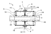
- FIG. 1 shows the bubble ratio sensor 1 according to the embodiment of the present disclosure. ..
- the bubble ratio sensor 1 has an insulating inner tube 2 having a through hole 3 through which liquid hydrogen flows, and an even number (two in this embodiment) mounted on the outer surface of the inner tube 2. ) Is provided with the electrode 4.
- annular portion 5 is attached to the outer peripheral portions of both ends of the inner pipe 2, and the outer pipe 6 is joined to the outer peripheral portion of the annular portion 5.
- the outer tube 6 has a first insertion hole 7 that opens in the radial direction.
- a first airtight terminal 8 is provided in the first insertion hole 7, and a conduction pin 9 individually connected to the electrode 4 is fixed in the first insertion hole 7.
- the insulating inner tube 2 means an inner tube having a volume resistivity value of 10 10 ⁇ ⁇ m or more at 20 ° C.
- the outer pipe 6 is provided with a vacuum exhaust valve 15 (for example, a needle valve for vacuum exhaust), and a vacuum space 10 (heat insulating layer) is formed between the inner pipe 2 and the outer pipe 6.
- a vacuum exhaust valve 15 for example, a needle valve for vacuum exhaust
- a vacuum space 10 heat insulating layer
- the heat insulating performance for the inner pipe 2 is ensured.
- the generation of bubbles due to the influence of the outside air temperature is suppressed, so that the measurement accuracy of the bubble rate is improved. That is, if the heat insulating performance is not sufficient between the inside and the outside of the inner pipe 2 through which the cryogenic liquid such as liquid nitrogen flows, the bubbles generated in the inner pipe 2 due to the influence of the external temperature cannot be sufficiently controlled. Therefore, it becomes difficult to accurately measure the bubble ratio of the ultra-low temperature liquid.
- the first airtight terminal 8 suppresses the leakage of liquid hydrogen from the inner pipe 2 to the outside, the measurement accuracy of the bubble ratio is further improved.
- the inner tube 2 is preferably made of ceramics, for example, ceramics containing aluminum oxide as a main component.
- ceramics containing aluminum oxide as a main component.
- the inner tube 2 having excellent mechanical properties can be obtained while the raw material price and the production cost are relatively low.
- the inner tube 2 When the inner tube 2 is made of ceramics containing aluminum oxide as a main component, it may contain, for example, silicon, magnesium and calcium. When these elements are converted into oxides out of the total 100% by mass of the components constituting the ceramics, for example, SiO 2 is 0.3% by mass to 1% by mass, MgO is 0.1% by mass to 0.4% by mass. , CaO is 0.04% by mass to 0.08% by mass.
- the inner tube 2 is preferably made of low thermal expansion ceramics.
- the low thermal expansion ceramics refer to ceramics having a linear expansion coefficient of 0 ⁇ 20 ppb / K or less at 22 ° C. Since the low thermal expansion ceramics have a low coefficient of linear expansion, the risk of damage is reduced even if they are subjected to thermal shock by a cryogenic liquid containing liquid hydrogen.
- the main crystal phase is cordierite
- the subcrystal phase contains alumina, mullite and sapphirine
- the grain boundary phase contains an amorphous phase containing Ca. ..
- the crystal phase ratio of the main crystal phase is 95% by mass or more and 97.5% by mass or less
- the crystal phase ratio of the sub-crystal phase is 2.5% by mass or more and 5% by mass or less
- the content of Ca in the total amount is 25% by mass or more and 5% by mass or less. It is 0.4% by mass or more and 0.6% by mass or less in terms of CaO, and further contains zirconia, and the content of zirconia in the total amount is 0.
- It is preferably 1% by mass or more and 1.0% by mass or less. Since the relative permittivity of the ceramics forming the inner tube 2 becomes close to the relative permittivity of the ultra-low temperature liquid and the high frequency characteristics are improved, the measurement accuracy of the bubble ratio is further improved.
- the inner tube 2 may be made of, for example, silicon nitride or ceramics containing sialon as a main component. Since these ceramics have high mechanical strength and thermal shock resistance, the risk of breakage is reduced even if they are subjected to thermal shock.
- the ceramics contain calcium oxide, aluminum oxide and oxides of rare earth elements, and contain calcium oxide and aluminum oxide with respect to a total of 100% by mass of the oxides of calcium oxide, aluminum oxide and rare earth elements.
- the amounts are 0.3% by mass or more and 1.5% by mass or less, 14.2% by mass or more and 48.8% by mass or less, respectively, and the balance is the oxide of the rare earth element.
- the main component of ceramics means a component that occupies 60% by mass or more of the total 100% by mass of the components constituting the ceramics.
- the main component is preferably a component that accounts for 95% by mass or more of the total 100% by mass of the components constituting the ceramics.
- the components constituting the ceramics may be obtained by using an X-ray diffractometer (XRD).
- XRD X-ray diffractometer
- the content of each component can be determined by determining the content of the elements constituting the component using a fluorescent X-ray analyzer (XRF) or an ICP emission spectroscopic analyzer after identifying the component and converting it into the identified component. good.
- the relative density of ceramics is, for example, 92% or more and 99.9% or less.
- the relative density is expressed as a percentage (ratio) of the apparent density of the ceramics obtained in accordance with JIS R1634-198 with respect to the theoretical density of the ceramics.
- Ceramics have closed pores, and the value obtained by subtracting the average value of the equivalent circle diameter of the closed pores from the average value of the distance between the centers of gravity of the adjacent closed pores (hereinafter, this value is referred to as the distance between the closed pores) is 8 ⁇ m. It may be 18 ⁇ m or more.
- the closed pores are independent of each other.
- the closed pores When the distance between the closed pores is 8 ⁇ m or more, the closed pores exist in a relatively dispersed state, so that the mechanical strength is high. On the other hand, when the distance between the closed pores is 18 ⁇ m or less, even if a cold shock is repeatedly applied and microcracks originating from the contour of the closed pores occur, there is a high probability that the extension will be blocked by the surrounding closed pores. Become. From this, if the distance between the closed pores is 8 ⁇ m or more and 18 ⁇ m or less, the inner tube 2 made of this ceramic can be used for a long period of time.
- the skewness of the circle-equivalent diameter of the closed pores may be larger than the skewness of the distance between the centers of gravity of the closed pores.
- the skewness is an index (statistic) indicating how much the distribution is distorted from the normal distribution, that is, the left-right symmetry of the distribution.
- the skewness is larger than 0, the tail of the distribution is on the right side.
- the distribution is symmetrical, and when the skewness is less than 0, the tail of the distribution is toward the left side.
- the skewness of the circle-equivalent diameter of the closed pores is larger than the skewness of the circle-equivalent diameter of the closed pores.
- the mode is located to the left (zero side) of the mode of the distance between the centers of gravity. That is, there are many closed pores having a small equivalent circle diameter, and these closed pores are more sparsely present, so that the inner pipe 2 has both mechanical strength and cold heat impact resistance.
- the skewness of the circle-equivalent diameter of the closed pores is 1 or more, and the skewness of the distance between the centers of gravity of the closed pores is 0.6 or less.
- the difference between the skewness of the circle-equivalent diameter of the closed pores and the skewness of the distance between the centers of gravity of the closed pores is 0.4 or more.
- the ceramic member is polished on a copper plate from one end face of the ceramic member in the axial direction using diamond abrasive grains having an average particle size D50 of 3 ⁇ m. Then, by polishing with a tin plate using diamond abrasive grains having an average particle size D 50 of 0.5 ⁇ m, a polished surface having an arithmetic average roughness Ra of 0.2 ⁇ m or less in the roughness curve is obtained.
- the arithmetic mean roughness Ra of the polished surface is the same as the above-mentioned measuring method. Observe the polished surface at a magnification of 200 times and select an average range, for example, an area of 7.2 x 10 4 ⁇ m 2 (horizontal length 310 ⁇ m, vertical length 233 ⁇ m). The area is photographed with a CCD camera to obtain an observation image.
- the distance between the centers of gravity of the dispersion measurement is used to open the pores.
- the distance between the centers of gravity may be obtained.
- the image analysis software "A image-kun” is described, the image analysis software manufactured by Asahi Kasei Engineering Co., Ltd. is shown.
- the threshold value which is an index indicating the lightness and darkness of the image may be 165, the lightness may be dark, the small figure removal area may be 1 ⁇ m 2 , and the noise removal filter may be omitted.
- the threshold value may be adjusted according to the brightness of the observed image, the brightness is darkened, the binarization method is manual, the small figure removal area is 1 ⁇ m 2 , and the noise removal filter is provided.
- the threshold value may be adjusted so that the marker appearing in the observation image matches the shape of the closed pores.
- the equivalent circle diameter of the closed pores the equivalent circle diameter of the open pores may be obtained by a method called particle analysis for the above observation image.
- the setting conditions may be the same as the setting conditions used for obtaining the distance between the centers of gravity of the closed pores.
- the skewness of the equivalent circle diameter and the distance between the centers of gravity of the closed pores may be obtained by using the function Skew provided in Excel (registered trademark, Microsoft Corporation), respectively.
- Aluminum oxide powder (purity of 99.9% by mass or more), which is the main component, and magnesium hydroxide, silicon oxide, and calcium carbonate powders are put into a pulverizing mill together with a solvent (ion-exchanged water) to prepare the powder. After pulverizing until the average particle size (D 50 ) becomes 1.5 ⁇ m or less, an organic binder and a dispersant for dispersing aluminum oxide powder are added and mixed to obtain a slurry.
- a solvent ion-exchanged water
- the content of the magnesium hydroxide powder is 0.3 to 0.42% by mass
- the content of the silicon oxide powder is 0.5 to 0.8% by mass
- the content is 0.06 to 0.1% by mass
- the balance is aluminum oxide powder and unavoidable impurities.
- the organic binder are acrylic emulsions, polyvinyl alcohols, polyethylene glycols, polyethylene oxides and the like.
- a columnar molded body is formed by pressurizing the molding pressure to 78 MPa or more and 118 MPa or less using a uniaxial press molding device or a cold hydrostatic pressure press molding device. obtain. If necessary, the molded body is formed with dents that become recesses after firing by cutting.
- the molded body is fired with the firing temperature set to 1580 ° C. or higher and 1780 ° C. or lower and the holding time set to 2 hours or longer and 4 hours or lower to obtain an inner tube made of ceramics.
- the molded product may be fired at a firing temperature of 1600 ° C. or higher and 1760 ° C. or lower and a holding time of 2 hours or longer and 4 hours or shorter.
- the surface of the ceramic member facing the pipeline may be ground to obtain a ground surface. Further, the surface of the recess in which the electrode is provided may be ground to form the bottom surface.
- the inner pipe 2 preferably has an inner diameter of 50 mm or more.
- the annular portion 5 is, for example, a Fernico alloy, Fe—Ni alloy, Fe—Ni—Cr—Ti—Al alloy, Fe—Cr—Al alloy, Fe—Co—Cr alloy, Fe—Co alloy, Fe—Co—. It is preferably formed of C alloy or austenite-based stainless steel having a nickel content of 10.4% by mass or more.
- the outer diameter of the annular portion 5 is preferably 1 mm or more with respect to the outer diameter of the inner pipe 2, preferably 10 mm or more with respect to the outer diameter of the inner pipe 2, in order to obtain sufficient heat insulating performance. It is preferably 200 mm or less, preferably 100 mm or less with respect to the outer diameter of the tube 2.
- the annular portion 5 is airtightly joined to the outer peripheral surface of the metallized inner tube 2 by brazing.
- the outer tube 6 is preferably formed of, for example, a metal such as austenitic stainless steel (for example, SUS316L) having a nickel content of 10.4% by mass or more, ceramics such as silicon nitride and sialon.
- a metal such as austenitic stainless steel (for example, SUS316L) having a nickel content of 10.4% by mass or more, ceramics such as silicon nitride and sialon.
- the first airtight terminal 8 constitutes a so-called hermetic connector, and is a disk-shaped first having a conduction pin 9 and a first pin hole (not shown) for inserting the conduction pin 9 in the thickness direction.
- a ceramic substrate 17 and a first annular body 18 surrounding the outer peripheral surface of the first ceramic substrate 17 are provided.
- the first annular body 18 functions as a sleeve for holding the first ceramic substrate 17, and for example, a Fernico alloy, Fe—Ni alloy, Fe—Ni—Cr—Ti—Al alloy, Fe—Cr—Al alloy, Fe.
- -It is preferably made of austenite-based stainless steel having a Co—Cr alloy, Fe—Co alloy, Fe—Co—C alloy or nickel content of 10.4% by mass or more.
- austenitic stainless steels having a nickel content of 10.4% by mass or more include SUS310S, SUS316L, SUS316LN, SUS316J1L, and SUS317L.
- the electrode 4 can be formed of, for example, copper foil, aluminum foil, or the like.
- the electrode 4 can be formed on the outer peripheral surface of the inner tube 2 by, for example, a vacuum vapor deposition method, a metallizing method, an active metal method, or the like. Further, a metal plate serving as an electrode 29 may be adhered to the bottom surface of the recess 28, which will be described later.
- the thickness of the electrodes 41 and 42 is preferably 10 ⁇ m or more, preferably 20 ⁇ m or more, and 1 mm or less, preferably 2 mm or less.
- a metal pipe 20 having a flange portion 19 is arranged at both ends of the inner pipe 2, and the annular portion 5 and the flange portion 19 are welded or brazed.
- the metal tube 20 may be a liquid hydrogen transfer tube for transferring liquid hydrogen.
- the bubble rate sensor 11 of this embodiment has a structure in which the inner tube 21 is surrounded by the housing 22 and the outside of the housing 22 is covered with the outer tube 26.
- the housing 22 has a second insertion hole 23 that opens in the radial direction on the outer peripheral surface, and further has a connecting hole 24 that opens along the axial direction of the inner pipe 21 and communicates with the through hole 31 of the inner pipe 21. ..
- Metal pipes 25 communicating with the through holes 31 of the inner pipe 21 via the connecting holes 24 are arranged at both ends of the housing 22.
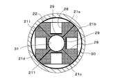
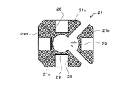
- the inner tube 21 has a recess 28 that opens toward the outside, and an electrode 29 is attached to the bottom surface of the recess 28. Further, as shown in FIGS. 3A and 3B, the inner tube 21 is composed of an even number of divisible (four in this embodiment) ceramic members 21a, 21b, 21c, 21d arranged in the circumferential direction.
- the side surfaces thereof are overlapped with each other, and an annular bundling body 30 is mounted on the outer peripheral surface to bind the ceramic members 21a, ... 21d.
- the housing 22 is attached to the outer peripheral side of the inner pipe 21. In other words, the housing 22 is provided to accommodate the divisible inner pipe 21.
- the housing 22 includes a frame body portion 22a for accommodating the inner tube 21 and a lid portion 22b for sealing the opening of the frame body portion 22a.
- the frame body portion 22a and the lid portion 22b are joined by welding or brazing.
- the frame body portion 22a and the lid portion 22b each have an opening that communicates with the through hole of the inner tube 21, and the metal tube 25 communicates with the through hole through each opening of the frame body portion 22a and the lid portion 22b. Welded or braided to each.
- the inner pipe 21 has a substantially quadrangular cross section, and has a shape in which the corner portion 211 is chamfered (C surface processed or R surface processed). Therefore, since the annular bundling body 30 presses the chamfered corners 211, the ceramic members 21a, ... 21d can be firmly bound.
- the binding body 30 include a strip-shaped flexible plastic film and a metal strip. At that time, both ends of the binding body 30 are joined by a joining means such as heat fusion or welding.
- the ceramic members 21a, ... 21d constituting the inner tube 21 are formed of low thermal expansion ceramics or ceramics containing aluminum oxide, silicon nitride or sialon as a main component, similarly to the inner tube 2 described above. good.
- At least one of the ceramic members 21a, ... 21d may have closed pores, and the distance between the closed pores may be 8 ⁇ m or more and 18 ⁇ m.
- the annular portion 51 is located on the outer side in the axial direction of the housing 22.
- the annular portion 51 has a shaft hole on the same axis as the inner pipe 21, and is welded or brazed to the outer peripheral surface of the metal pipe 25 inserted through the shaft hole.
- An outer pipe 26 is joined to the outer peripheral portion of the annular portion 51.
- the outer tube 26 has a first insertion hole 27 that opens in the radial direction on the outer peripheral surface.
- a first airtight terminal 81 for fixing a conduction pin 91 individually connected to each electrode 29 is provided in the first insertion hole 27.
- the first airtight terminal 81 has a disk shape having a conduction pin 91 and a first pin hole (not shown) for inserting the conduction pin 91 in the thickness direction, similarly to the first airtight terminal 8 described above. It is composed of a first ceramic substrate 50 and a first annular body 52 surrounding the outer peripheral surface of the first ceramic substrate 50.
- the second insertion hole 23 provided on the outer peripheral surface of the housing 22 is also provided with a second airtight terminal 82 for fixing the conduction pin 91 in the second insertion hole.
- the second airtight terminal 82 includes a conduction pin 91, a disk-shaped second ceramic substrate 50'provided with a second pin hole (not shown) for inserting the conduction pin 91 in the thickness direction, and a second. It is composed of a second annular body 52'that surrounds the outer peripheral surface of the ceramic substrate 50'.
- the outer pipe 26 is provided with a vacuum exhaust valve 15 (for example, a needle valve for vacuum exhaust), and forms a vacuum space 100 (heat insulating layer) between the housing 22 and the outer pipe 26.
- a vacuum exhaust valve 15 for example, a needle valve for vacuum exhaust
- the space between the inner pipe 21 and the housing 22 may also be a vacuum space. Since the vacuum space 100 is located between the housing 22 and the outer pipe 26 in this way, the vaporization of liquid hydrogen due to the outside air temperature is suppressed, the heat insulating performance for the inner pipe 21 is improved, and bubbles are generated. It is suppressed and the measurement accuracy of the bubble ratio is improved.
- Others are the same as those of the embodiment shown in FIG. 1, and detailed description thereof will be omitted.
- FIGS. 4 to 6 modifications to the embodiments shown in FIGS. 2 and 3A and 3B are shown in FIGS. 4 to 6.
- the same members as the constituent members of the bubble rate sensor 11 shown in FIGS. 2 and 3A and 3B are designated by the same reference numerals, and the description thereof will be omitted.
- the metal pipe 25' is directly joined to the inner pipe 21'.
- the frame body portion 22a ′ and the lid portion 22b ′ constituting the housing 22 ′ are integrally formed with the metal tube 25 ′ or joined to the metal tube 25 ′.
- the outer tube 26' is joined to the outer peripheral surface of the housing 22'. The joining can be performed, for example, by welding or brazing.
- a vacuum exhaust valve 15 is provided on the outer pipe 26', and a vacuum space 100' (insulation layer) is formed between the inner pipe 21'and the outer pipe 26'.
- the inner tube 21' is composed of four ceramic members 21a', 21b', 21c', 21d', and is integrally joined by a binding body 30'. Details are as shown in FIGS. 3A and 3B.
- the inner tube is not limited to a substantially quadrangular cross section, and the cross-sectional shape may be a circle or another polygon.
- the number of ceramic members constituting the inner pipe is an even number, for example, 2, 4, 6, or 8. This is because at least a pair of opposing electrodes are required to measure the capacitance, and each electrode is attached to a ceramic member.
- the electrodes are provided on at least a pair of ceramic members facing each other. It may be just.
- This current meter measures the flow rate of liquid hydrogen flowing in the inner tubes 2, 21, 21', and the above-mentioned bubble ratio sensors 1, 11, 111 and the ultra-low temperature liquid (not shown) are through holes 3; A current meter for measuring the flow velocity flowing in the 31 is provided.
- the bubble rate sensors 1, 11, 111 and the current meter are attached to a liquid hydrogen transfer pipe (hereinafter, may be abbreviated as a transfer pipe) (not shown).
- the electrostatic capacity of the liquid hydrogen is measured by the bubble ratio sensors 1, 11 and 111, and the density d of the liquid hydrogen is determined from this. (Kg / m 3 ) can be obtained.
- the flow meter further includes an arithmetic unit to which the bubble rate sensors 1, 11, 111 and the current meter are connected in order to perform the above calculation.
- the flow rate of liquid hydrogen can be easily measured, which facilitates management when a large amount of liquid hydrogen is industrially transferred.
- the bubble ratio sensors 1, 11, 111 of liquid hydrogen and the flow meter using the same have been described, but other ultra-low temperature liquids such as liquid nitrogen (-196 ° C) and liquid helium (-269 ° C) have been described.
- liquid nitrogen -196 ° C
- liquid helium -269 ° C
- Liquefied natural gas -162 ° C.
- liquid argon -186 ° C.
- the cryogenic liquid in the present disclosure means a liquid that liquefies at a cryogenic temperature of -162 ° C or lower. It was
- the bubble rate sensor of the present disclosure is not limited to the above embodiment, and various changes and improvements can be made within the scope of the present disclosure.
Landscapes
- Physics & Mathematics (AREA)
- General Physics & Mathematics (AREA)
- Chemical & Material Sciences (AREA)
- Fluid Mechanics (AREA)
- Analytical Chemistry (AREA)
- Electrochemistry (AREA)
- Health & Medical Sciences (AREA)
- Life Sciences & Earth Sciences (AREA)
- Chemical Kinetics & Catalysis (AREA)
- Biochemistry (AREA)
- General Health & Medical Sciences (AREA)
- Immunology (AREA)
- Pathology (AREA)
- Investigating Or Analyzing Materials By The Use Of Electric Means (AREA)
- Rigid Pipes And Flexible Pipes (AREA)
- Measuring Volume Flow (AREA)
- Ceramic Products (AREA)
Abstract
Description
図1は本開示の一実施形態に係る気泡率センサ1を示している。図1に示すように、この気泡率センサ1は、液体水素が流れる貫通孔3を有する絶縁性の内管2と、該内管2の外面に装着された偶数個(本実施形態では2個)の電極4とを備える。
研磨面を200倍の倍率で観察し、平均的な範囲を選択して、例えば、面積が7.2×104μm2(横方向の長さが310μm、縦方向の長さが233μm)となる範囲をCCDカメラで撮影して、観察像を得る。
流量計は、上記演算を行うために、気泡率センサ1、11、111および流速計が接続された演算装置をさらに備えている。これにより、液体水素の流量測定を簡単に行うことができるので、工業的に液体水素を大量移送する場合に管理が容易になる。
2、21、21´ 内管
21a、21b、21c、21d セラミック部材
21a´、21b´、21c´、21d´ セラミック部材
211 角部
3、31 貫通孔
4、29 電極
5 環状部
6 外管
7 第1挿通孔
8、81 第1気密端子
82 第2気密端子
9、91 導通ピン
10、100、100´ 真空空間
15 真空排気弁
17,50 第1セラミック基板
18、52 第1環状体
19 フランジ部
20、25、25´ 金属管
22、22´ 筐体
22a、22a´ 枠体部
22b、22b´ 蓋部
23 第2挿通孔
24 連結孔
26、26´ 外管
27 第1挿通孔
28 凹部
29 電極
30 結束体
50´ 第2セラミック基板
51 環状部
52´ 第2環状体
Claims (15)
- 極低温液体を流すための貫通孔を有する絶縁性の内管と、該内管の外面に装着された少なくとも一対の電極と、前記内管の外周側を覆う断熱層とを備えた、気泡率センサ。
- 前記内管の両端部に設けられる環状部と、
該環状部の外周部に接合され、第1挿通孔を有する外管と、
前記第1挿通孔内に設けられ、前記電極に個別に接続する導通ピンを前記第1挿通孔内で固定する第1気密端子と、を備え、
前記断熱層は、前記内管と前記外管との間に位置する真空空間である、請求項1に記載の気泡率センサ。 - 前記第1気密端子は、前記導通ピンと、該導通ピンを挿入するための第1ピン孔を厚み方向に備えた円板状のセラミック基板と、該セラミック基板の外周面を囲繞する環状体と、を備え、該環状体はフェルニコ系合金、Fe-Ni合金、Fe-Ni-Cr-Ti-Al合金、Fe-Cr-Al合金、Fe-Co-Cr合金、Fe-Co合金、Fe-Co-C合金またはニッケルの含有量が10.4質量%以上であるオーステナイト系ステンレス鋼からなる、請求項2に記載の気泡率センサ。
- フランジ部を有する金属管を前記内管の少なくともいずれか一端に備え、前記環状部と前記フランジ部とが溶接またはろう接されてなる、請求項2または3に記載の気泡率センサ。
- 前記内管は、周方向に配列された分割可能な偶数個のセラミック部材からなり、
前記内管を囲繞し、第2挿通孔と、前記内管の前記貫通孔と連通する連結孔とを有する筐体と、
該筐体の外側に位置し、前記内管と同一軸心上に軸孔を有する環状部と、
該環状部の外周部に接合され、第1挿通孔を有する外管と、
前記電極に個別に接続する導通ピンを前記第1挿通孔内で固定する第1気密端子と、
前記導通ピンを前記第2挿通孔内で固定する第2気密端子と、を備えてなり、
前記真空空間は、少なくとも前記外管と前記筐体との間に位置する、請求項1に記載の気泡率センサ。 - 前記第1気密端子および前記第2気密端子は、いずれも、前記導通ピンと、該導通ピンを挿入するためのピン孔を厚み方向に備えた円板状のセラミック基板と、該セラミック基板の外周面を囲繞する環状体と、を有し、該環状体はフェルニコ系合金、Fe-Ni合金、Fe-Ni-Cr-Ti-Al合金、Fe-Cr-Al合金、Fe-Co-Cr合金、Fe-Co合金、Fe-Co-C合金またはニッケルの含有量が10.4質量%以上であるオーステナイト系ステンレス鋼からなる、請求項5に記載の気泡率センサ。
- 前記内管は、外部に向かって開口する凹部を有し、該凹部の底面に前記電極が装着されてなる、請求項5~6のいずれかに記載の気泡率センサ。
- 偶数個の前記セラミック部材のうち、互いに対向する少なくとも一対のセラミック部材に前記電極がそれぞれ設けられている、請求項5~7のいずれかに記載の気泡率センサ。
- 前記内管の外周側に、前記セラミック部材を結束する環状の結束体を装着してなる、請求項5~8のいずれかに記載の気泡率センサ。
- 前記内管の端面および外側面の少なくともいずれかは、前記筐体の内面に当接されてなる、請求項5~9のいずれかに気泡率センサ。
- 前記筐体は、前記内管を収容する枠体部と、該枠体部の開口を封止する蓋部とを備え、前記枠体部および前記蓋部は前記内管の貫通孔に連通する開口をそれぞれ有し、該各開口を介して前記貫通孔と連通するように金属管が前記枠体部および前記蓋部に溶接またはろう接されてなる、請求項5~10のいずれかに記載の気泡率センサ。
- 前記環状部は、前記金属管に溶接またはろう接されてなる、請求項11に記載の気泡率センサ。
- 前記内管は、低熱膨張セラミックスからなる、請求項1~12のいずれかに記載の気泡率センサ。
- 前記内管の貫通孔内を流れる極低温液体の流量を測定する流量計であって、請求項1~13のいずれかに記載の気泡率センサと、前記極低温液体が前記貫通孔内を流れる流速を測定する流速計とを備えた流量計。
- 請求項14に記載の流量計を備えた極低温液体移送管。
Priority Applications (5)
| Application Number | Priority Date | Filing Date | Title |
|---|---|---|---|
| CN202180081096.7A CN116547501A (zh) | 2020-12-09 | 2021-12-09 | 气泡率传感器、利用其的流量计以及极低温液体移送管 |
| KR1020237018723A KR102883038B1 (ko) | 2020-12-09 | 2021-12-09 | 기포율 센서, 이것을 사용한 유량계 및 극저온 액체 이송관 |
| US18/266,229 US20240118232A1 (en) | 2020-12-09 | 2021-12-09 | Void fraction sensor, flowmeter using the same, and cryogenic liquid transfer pipe |
| EP21903476.6A EP4261532A4 (en) | 2020-12-09 | 2021-12-09 | CAVITY FRACTION SENSOR, FLOW METER AND CRYOGENIC LIQUID TRANSFER TUBE |
| JP2022568337A JP7489490B2 (ja) | 2020-12-09 | 2021-12-09 | 気泡率センサ、これを用いた流量計および極低温液体移送管 |
Applications Claiming Priority (2)
| Application Number | Priority Date | Filing Date | Title |
|---|---|---|---|
| JP2020204567 | 2020-12-09 | ||
| JP2020-204567 | 2020-12-09 |
Publications (1)
| Publication Number | Publication Date |
|---|---|
| WO2022124377A1 true WO2022124377A1 (ja) | 2022-06-16 |
Family
ID=81973347
Family Applications (1)
| Application Number | Title | Priority Date | Filing Date |
|---|---|---|---|
| PCT/JP2021/045383 Ceased WO2022124377A1 (ja) | 2020-12-09 | 2021-12-09 | 気泡率センサ、これを用いた流量計および極低温液体移送管 |
Country Status (6)
| Country | Link |
|---|---|
| US (1) | US20240118232A1 (ja) |
| EP (1) | EP4261532A4 (ja) |
| JP (1) | JP7489490B2 (ja) |
| KR (1) | KR102883038B1 (ja) |
| CN (1) | CN116547501A (ja) |
| WO (1) | WO2022124377A1 (ja) |
Cited By (3)
| Publication number | Priority date | Publication date | Assignee | Title |
|---|---|---|---|---|
| JPWO2023063396A1 (ja) * | 2021-10-15 | 2023-04-20 | ||
| WO2023100793A1 (ja) * | 2021-11-30 | 2023-06-08 | 京セラ株式会社 | 気泡率計 |
| WO2024106473A1 (ja) * | 2022-11-16 | 2024-05-23 | 京セラ株式会社 | 気泡率センサ、これを用いた流量計および極低温液体移送管 |
Citations (13)
| Publication number | Priority date | Publication date | Assignee | Title |
|---|---|---|---|---|
| JPS5472556U (ja) * | 1977-11-01 | 1979-05-23 | ||
| JPS54147519A (en) * | 1978-05-11 | 1979-11-17 | Kyushu Refractories | Large caliber ceramic pipe |
| JPS63214620A (ja) * | 1987-03-04 | 1988-09-07 | Furukawa Electric Co Ltd:The | 流量測定装置 |
| JPH0193559U (ja) * | 1987-12-15 | 1989-06-20 | ||
| JPH02212699A (ja) * | 1989-02-13 | 1990-08-23 | Iwatani Internatl Corp | 液体ヘリウムの貯蔵装置 |
| JPH06222030A (ja) * | 1993-01-25 | 1994-08-12 | Unisia Jecs Corp | 静電容量センサ |
| JPH06241382A (ja) * | 1993-02-10 | 1994-08-30 | Nissan Techno Service Kk | 多重層真空断熱法及び断熱二重管 |
| JPH0735670A (ja) * | 1993-07-16 | 1995-02-07 | Mitsubishi Heavy Ind Ltd | 極低温流体用密度計 |
| JPH11153290A (ja) * | 1997-11-21 | 1999-06-08 | Kazuhiro Oikawa | 真空断熱配管 |
| JP2004019813A (ja) * | 2002-06-18 | 2004-01-22 | Mitsubishi Heavy Ind Ltd | 低温流体用多重配管 |
| JP2005235577A (ja) * | 2004-02-19 | 2005-09-02 | Kyocera Corp | 気密端子 |
| JP2014524566A (ja) * | 2011-08-02 | 2014-09-22 | スネクマ | 2相流におけるガス含有量を測定するための多電極センサ |
| US20140331783A1 (en) * | 2011-12-06 | 2014-11-13 | Schlumberger Technology Corporation | Multiphase flowmeter |
Family Cites Families (14)
| Publication number | Priority date | Publication date | Assignee | Title |
|---|---|---|---|---|
| JPS62187181A (ja) * | 1986-02-12 | 1987-08-15 | 株式会社東芝 | 導電性棒体のセラミツクス体への内嵌封着方法 |
| JPH01193559A (ja) * | 1988-01-27 | 1989-08-03 | Kawasaki Heavy Ind Ltd | 高温蓄熱システム |
| JPH0735588A (ja) * | 1993-07-21 | 1995-02-07 | Hitachi Ltd | 電磁流量計 |
| JPH10282032A (ja) * | 1997-04-02 | 1998-10-23 | Sekiyu Kodan | 混合物体積割合測定センサ |
| JP2001004423A (ja) * | 1999-06-24 | 2001-01-12 | Mitsui Mining & Smelting Co Ltd | 流量センサー |
| JP2001235067A (ja) * | 2000-02-23 | 2001-08-31 | Fuji Electric Co Ltd | ガラス等の管と金属管とからなるクラッド管の製造方法 |
| KR100413848B1 (ko) * | 2001-09-15 | 2004-01-03 | 주식회사 래피더스 | 광모듈용 밀폐형 패키지 |
| DE10261755A1 (de) * | 2002-01-04 | 2003-08-07 | Schott Glas | Verbundglasrohr |
| US9275762B2 (en) * | 2010-10-08 | 2016-03-01 | Advanced Ceramic Fibers, Llc | Cladding material, tube including such cladding material and methods of forming the same |
| JP2014115164A (ja) * | 2012-12-07 | 2014-06-26 | Mitsubishi Heavy Ind Ltd | 気液二相流の流量計測装置、流量計測方法及び流量計測用コンピュータプログラム |
| JP2014232007A (ja) * | 2013-05-28 | 2014-12-11 | 独立行政法人 宇宙航空研究開発機構 | 気液二相の流量計測方法及び二相流量計測装置 |
| CN204439149U (zh) * | 2015-01-29 | 2015-07-01 | 兖矿水煤浆气化及煤化工国家工程研究中心有限公司 | 浓相粉煤质量流量计 |
| CN104965010B (zh) * | 2015-06-29 | 2018-09-11 | 浙江大学 | 一种低温电容式空泡率测量装置 |
| US10416107B2 (en) * | 2016-08-19 | 2019-09-17 | Ecolab Usa Inc. | Conductivity sensor with void correction |
-
2021
- 2021-12-09 KR KR1020237018723A patent/KR102883038B1/ko active Active
- 2021-12-09 CN CN202180081096.7A patent/CN116547501A/zh active Pending
- 2021-12-09 JP JP2022568337A patent/JP7489490B2/ja active Active
- 2021-12-09 WO PCT/JP2021/045383 patent/WO2022124377A1/ja not_active Ceased
- 2021-12-09 US US18/266,229 patent/US20240118232A1/en active Pending
- 2021-12-09 EP EP21903476.6A patent/EP4261532A4/en active Pending
Patent Citations (13)
| Publication number | Priority date | Publication date | Assignee | Title |
|---|---|---|---|---|
| JPS5472556U (ja) * | 1977-11-01 | 1979-05-23 | ||
| JPS54147519A (en) * | 1978-05-11 | 1979-11-17 | Kyushu Refractories | Large caliber ceramic pipe |
| JPS63214620A (ja) * | 1987-03-04 | 1988-09-07 | Furukawa Electric Co Ltd:The | 流量測定装置 |
| JPH0193559U (ja) * | 1987-12-15 | 1989-06-20 | ||
| JPH02212699A (ja) * | 1989-02-13 | 1990-08-23 | Iwatani Internatl Corp | 液体ヘリウムの貯蔵装置 |
| JPH06222030A (ja) * | 1993-01-25 | 1994-08-12 | Unisia Jecs Corp | 静電容量センサ |
| JPH06241382A (ja) * | 1993-02-10 | 1994-08-30 | Nissan Techno Service Kk | 多重層真空断熱法及び断熱二重管 |
| JPH0735670A (ja) * | 1993-07-16 | 1995-02-07 | Mitsubishi Heavy Ind Ltd | 極低温流体用密度計 |
| JPH11153290A (ja) * | 1997-11-21 | 1999-06-08 | Kazuhiro Oikawa | 真空断熱配管 |
| JP2004019813A (ja) * | 2002-06-18 | 2004-01-22 | Mitsubishi Heavy Ind Ltd | 低温流体用多重配管 |
| JP2005235577A (ja) * | 2004-02-19 | 2005-09-02 | Kyocera Corp | 気密端子 |
| JP2014524566A (ja) * | 2011-08-02 | 2014-09-22 | スネクマ | 2相流におけるガス含有量を測定するための多電極センサ |
| US20140331783A1 (en) * | 2011-12-06 | 2014-11-13 | Schlumberger Technology Corporation | Multiphase flowmeter |
Non-Patent Citations (2)
| Title |
|---|
| NORIHIDE MAENO ET AL.: "Void Fraction Measurement of Cryogenic Two Phase Flow Using a Capacitance Sensor", TRANS. JSASS AEROSPACE TECH. JAPAN, vol. 12, no. 29, 2014, pages Pa-101 - Pa-107 |
| See also references of EP4261532A4 |
Cited By (5)
| Publication number | Priority date | Publication date | Assignee | Title |
|---|---|---|---|---|
| JPWO2023063396A1 (ja) * | 2021-10-15 | 2023-04-20 | ||
| WO2023100793A1 (ja) * | 2021-11-30 | 2023-06-08 | 京セラ株式会社 | 気泡率計 |
| JPWO2023100793A1 (ja) * | 2021-11-30 | 2023-06-08 | ||
| JP7692054B2 (ja) | 2021-11-30 | 2025-06-12 | 京セラ株式会社 | 気泡率計 |
| WO2024106473A1 (ja) * | 2022-11-16 | 2024-05-23 | 京セラ株式会社 | 気泡率センサ、これを用いた流量計および極低温液体移送管 |
Also Published As
| Publication number | Publication date |
|---|---|
| KR102883038B1 (ko) | 2025-11-07 |
| CN116547501A (zh) | 2023-08-04 |
| EP4261532A1 (en) | 2023-10-18 |
| JPWO2022124377A1 (ja) | 2022-06-16 |
| JP7489490B2 (ja) | 2024-05-23 |
| KR20230098645A (ko) | 2023-07-04 |
| US20240118232A1 (en) | 2024-04-11 |
| EP4261532A4 (en) | 2024-11-06 |
Similar Documents
| Publication | Publication Date | Title |
|---|---|---|
| JP7489490B2 (ja) | 気泡率センサ、これを用いた流量計および極低温液体移送管 | |
| JP7511031B2 (ja) | 気泡率センサ、これを用いた流量計および極低温液体移送管 | |
| CN102519289A (zh) | 环路热管蒸发器的一体化制备工艺 | |
| JP7489489B2 (ja) | 気泡率センサ、これを用いた流量計および極低温液体移送管 | |
| JP7524352B2 (ja) | 気泡率センサおよびこれを用いた流量計ならびに極低温液体移送管 | |
| US20220170808A1 (en) | Pressure sensor and method of manufacturing the same | |
| EP4621400A1 (en) | Bubble fraction sensor, flowmeter employing same, and cryogenic liquid transfer tube | |
| US20260110654A1 (en) | Void fraction sensor, flowmeter using the same, and liquid transfer pipe | |
| WO2012102378A1 (ja) | 炭化珪素質接合体およびこれからなる伝熱管ならびにこの伝熱管を備える熱交換器 | |
| JP7037662B2 (ja) | 気密端子 | |
| JP2003004546A (ja) | 金属溶湯用熱電対 | |
| JPS6271825A (ja) | 赤外検知器 |
Legal Events
| Date | Code | Title | Description |
|---|---|---|---|
| 121 | Ep: the epo has been informed by wipo that ep was designated in this application |
Ref document number: 21903476 Country of ref document: EP Kind code of ref document: A1 |
|
| ENP | Entry into the national phase |
Ref document number: 2022568337 Country of ref document: JP Kind code of ref document: A |
|
| WWE | Wipo information: entry into national phase |
Ref document number: 202180081096.7 Country of ref document: CN |
|
| ENP | Entry into the national phase |
Ref document number: 20237018723 Country of ref document: KR Kind code of ref document: A |
|
| WWE | Wipo information: entry into national phase |
Ref document number: 18266229 Country of ref document: US |
|
| NENP | Non-entry into the national phase |
Ref country code: DE |
|
| ENP | Entry into the national phase |
Ref document number: 2021903476 Country of ref document: EP Effective date: 20230710 |