WO2022130470A1 - Élément d'échange de chaleur total et dispositif de ventilation à échange de chaleur total - Google Patents
Élément d'échange de chaleur total et dispositif de ventilation à échange de chaleur total Download PDFInfo
- Publication number
- WO2022130470A1 WO2022130470A1 PCT/JP2020/046584 JP2020046584W WO2022130470A1 WO 2022130470 A1 WO2022130470 A1 WO 2022130470A1 JP 2020046584 W JP2020046584 W JP 2020046584W WO 2022130470 A1 WO2022130470 A1 WO 2022130470A1
- Authority
- WO
- WIPO (PCT)
- Prior art keywords
- heat exchange
- total heat
- air
- exchange element
- flow
- Prior art date
- Legal status (The legal status is an assumption and is not a legal conclusion. Google has not performed a legal analysis and makes no representation as to the accuracy of the status listed.)
- Ceased
Links
Images

Classifications
-
- F—MECHANICAL ENGINEERING; LIGHTING; HEATING; WEAPONS; BLASTING
- F24—HEATING; RANGES; VENTILATING
- F24F—AIR-CONDITIONING; AIR-HUMIDIFICATION; VENTILATION; USE OF AIR CURRENTS FOR SCREENING
- F24F7/00—Ventilation
- F24F7/04—Ventilation with ducting systems, e.g. by double walls; with natural circulation
- F24F7/06—Ventilation with ducting systems, e.g. by double walls; with natural circulation with forced air circulation, e.g. by fan positioning of a ventilator in or against a conduit
- F24F7/08—Ventilation with ducting systems, e.g. by double walls; with natural circulation with forced air circulation, e.g. by fan positioning of a ventilator in or against a conduit with separate ducts for supplied and exhausted air with provisions for reversal of the input and output systems
-
- F—MECHANICAL ENGINEERING; LIGHTING; HEATING; WEAPONS; BLASTING
- F28—HEAT EXCHANGE IN GENERAL
- F28F—DETAILS OF HEAT-EXCHANGE AND HEAT-TRANSFER APPARATUS, OF GENERAL APPLICATION
- F28F3/00—Plate-like or laminated elements; Assemblies of plate-like or laminated elements
- F28F3/08—Elements constructed for building-up into stacks, e.g. capable of being taken apart for cleaning
Definitions
- the present disclosure relates to a total heat exchange element and a total heat exchange ventilator capable of exchanging temperature and humidity, that is, total heat between the supply air flow and the exhaust flow.
- the indoor air quality can be systematically secured by ventilation, but considering the cooling and heating efficiency of the air conditioning in the room, the ventilation load, which is the air conditioning load by ventilation, can be suppressed. Ensuring indoor air quality is a contradictory issue.
- a ventilation method that achieves both of these, there is a method of exchanging heat between the supply air flow and the exhaust flow, but in order to further reduce the ventilation load, the temperature, that is, sensible heat, is used between the supply air flow and the exhaust flow.
- total heat exchange which also exchanges humidity, that is, sensible heat, is effective.
- One of the total heat exchange elements which is an element for performing total heat exchange, is a static total heat exchange element in which the supply air passage and the exhaust air passage are formed as independent air passages with a partition plate in between. be.
- the air supply air passage and the exhaust air passage are each composed of a substantially corrugated spacing plate formed by corrugated processing, and the air supply airflow flowing through the air supply air passage and the exhaust flow flowing through the exhaust air passage are described. Total heat exchange takes place between them. Therefore, it is known that the ventilation load can be suppressed and the cooling and heating energy of the indoor air conditioner can be saved by ventilating the indoor air with the total heat exchange ventilation device equipped with the total heat exchange element. There is.
- the humidity recovery direction has been determined by the air conditions including the indoor and outdoor temperatures and humidity. That is, it was not possible to intentionally select the direction of collecting humidity from indoors to outdoors or from outdoors to indoors.
- Patent Document 1 an indoor heat exchanger for air conditioning and a humidifying element are arranged in front of the air supply port of the total heat exchange ventilation device, and in winter, heating with a refrigerant and humidification operation are performed by a humidifying element, and in summer.
- the present disclosure is made in view of the above and is a total heat exchange capable of humidifying or dehumidifying a room depending on the indoor and outdoor air environment without using electric power for humidification and dehumidification.
- the purpose is to obtain an element.
- the total heat exchange element of the present disclosure includes a partition member and a space-holding member for holding a space between the partition members, and the partition member and the space-holding member.
- the partition member is a first surface material which is a material of the surface exposed to the first flow path and a second surface which is a material of the surface exposed to the second flow path and is composed of a material different from the first surface material. With the material.
- the total heat exchange element according to the present disclosure has an effect that the room can be humidified or dehumidified according to the indoor and outdoor air environment without using electric power for humidification and dehumidification.
- Partial vertical cross-sectional view schematically showing an example of the flow path cross section of the exhaust air passage of the total heat exchange element according to the first embodiment.
- Sectional drawing which shows typically an example of the partition member which concerns on Embodiment 1.
- the figure which shows typically the moisture permeability performance of the partition member which concerns on Embodiment 1.
- Top view schematically showing an example of the configuration of the partition member according to the first embodiment on the non-woven fabric layer side.
- Sectional drawing which schematically shows an example of the procedure of the manufacturing method of the total heat exchange element which concerns on Embodiment 1.
- Sectional drawing which shows typically an example of the procedure of the manufacturing method of the total heat exchange element which concerns on Embodiment 1.
- Sectional drawing which schematically shows an example of the procedure of the manufacturing method of the total heat exchange element which concerns on Embodiment 1.
- the figure which shows an example of the schematic structure of the total heat exchange ventilation apparatus which concerns on Embodiment 1.
- Partial vertical cross-sectional view schematically showing another example of the flow path cross section of the exhaust air passage of the total heat exchange element according to the first embodiment.
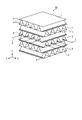
- FIG. 1 is a perspective view schematically showing an example of a schematic configuration of the total heat exchange element according to the first embodiment.
- the extending direction of the first flow path 4 described later is the X direction
- the extending direction of the second flow path 5 orthogonal to the first flow path 4 is the Y direction
- the orthogonal direction is the Z direction.
- the total heat exchange element 10 includes a flat plate-shaped partition member 1, an interval holding member 2, and an adhesive portion 3.
- the partition members 1 are laminated in the Z direction at predetermined intervals.
- the space holding member 2 is a corrugated member that holds the space between the partition members 1 adjacent to each other in the Z direction.
- the corrugated shape refers to a corrugated shape composed of peaks and valleys. In the space holding members 2 adjacent to each other in the Z direction, the extending directions of the peaks and valleys are orthogonal to each other in the plane of the partition member 1, that is, in the XY plane. That is, in the example of FIG.
- the adhesive portion 3 is a portion that joins the mountain portion and the valley portion of the interval holding member 2 and the partition member 1.
- the adhesive portion 3 is a portion where the mountain portion and the valley portion of the interval holding member 2 and the partition member 1 are joined by a joining member such as an adhesive.
- the partition member 1 and the spacing member 2 form a flow path through which air flows in the X and Y directions.
- a first flow path 4 extending in the X direction is formed by the interval holding member 2 in which the extending direction of the mountain portion and the valley portion is the X direction and the partition member 1 joined in the Z direction of the interval holding member 2. Will be done.
- a second flow path 5 extending in the Y direction is formed by the interval holding member 2 in which the extending direction of the mountain portion and the valley portion is the Y direction and the partition member 1 joined in the Z direction of the interval holding member 2. Will be done.
- the first flow path 4 is arranged in layers every other step in the Z direction
- the second flow path 5 is arranged in layers every other step in the Z direction.
- Latent heat and sensible heat are generated between the first air flow 6 which is the flow of air flowing through the first flow path 4 and the second air flow 7 which is the flow of air flowing through the second flow path 5 using the partition member 1 as a medium. Will be exchanged.
- the total heat exchange element 10 has the partition member 1 and the interval holding member 2 for holding the interval between the partition members 1, and the partition member 1 and the interval holding member 2 are alternately laminated and partitioned.
- Temperature and humidity, that is, total heat are transferred between the air flow, which is the flow of air flowing through the first flow path 4 and the second flow path 5, which are composed of the partition member 1 and the spacing member 2 with the member 1 sandwiched between them. It is a device to be replaced.
- the first airflow 6 is a supply airflow that is the flow of air from the outside to the room in the air conditioner including the total heat exchange element 10
- the second airflow 7 is the air flow from the room to the outside in the air conditioner.
- the case of an exhaust flow, which is an air flow, is taken as an example. Further, in this case, the first flow path 4 becomes the supply air passage 4a, and the second flow path 5 becomes the exhaust air passage 5a.
- the space holding member 2 has a corrugated shape, but the space holding member 2 may be any as long as it can hold the space between the partition members 1 at a predetermined space.
- the space holding member 2 may be any as long as it can hold the space between the partition members 1 at a predetermined space.
- a sheet bent into a rectangular wavy shape or a triangular wavy shape, a plurality of plate pieces, or the like may be used.
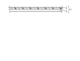
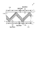
- FIG. 2 is a partial vertical cross-sectional view schematically showing an example of a flow path cross section of an exhaust air passage of the total heat exchange element according to the first embodiment.
- FIG. 2 is a diagram showing the interval holding member 2 and the partition members 1 above and below the interval holding member 2 extracted from the flow path cross section of the exhaust air passage 5a which is the second flow path 5.
- the partition member 1 is a composite membrane including the moisture permeable resin layer 8.
- the moisture permeable resin layer 8 may contain a moisture adsorbent in the air such as a hygroscopic agent.
- the partition member 1 has a moisture-permeable resin layer 8 and a nonwoven fabric layer 9 which is a base material layer.
- the moisture-permeable resin layer 8 and the non-woven fabric layer 9 are in the form of a sheet and are laminated with each other.
- the moisture permeable resin layer 8 is joined to the nonwoven fabric layer 9 with an adhesive or the like.
- the space holding member 2 is a material constituting a normal total heat exchange element such as specially processed paper.
- the total heat exchange element 10 has a form in which the surface of the moisture permeable resin layer 8 of the partition member 1 is exposed to the exhaust air passage 5a, from the exhaust air passage 5a to the supply air passage 4a.
- Moisture permeability that is, humidity exchange can be greatly taken. Further, the humidity exchange from the supply air passage 4a to the exhaust air passage 5a becomes relatively small. As a result, the operation of humidifying from the exhaust air passage 5a to the supply air passage 4a is realized.
- the partition member 1 is exposed to the first surface material which is the material of the surface exposed to the air supply air passage 4a and the exhaust air passage 5a. It can be said that it has a second surface material which is a material of the surface to be exposed and is composed of a material different from the first surface material. At this time, the moisture permeability of the first surface material and the moisture permeability of the second surface material are different from each other.
- the first surface material is a porous membrane material
- the second surface material is a gas barrier membrane having a moisture permeability that allows water vapor to pass through but does not allow oxygen and nitrogen, which are the main components of air, to pass through.
- the first surface material is the non-woven fabric layer 9, and the second surface material is the moisture-permeable resin layer 8.
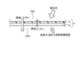
- FIG. 3 is a cross-sectional view schematically showing an example of the partition member according to the first embodiment.
- the partition member 1 is a composite film in which a moisture-permeable resin layer 8 and a non-woven fabric layer 9 which is a base material layer are bonded together.
- the moisture permeable resin layer 8 has a hygroscopic ability to adsorb water vapor in the air, that is, humidity.
- Moisture absorption capacity is defined by the unit area and the amount of moisture absorption per unit time. The amount of moisture absorbed is proportional to the contact area between the moisture permeable resin layer 8 and air.
- the amount of moisture absorbed on the moisture permeable resin layer 8 side of the partition member 1 becomes large.
- the non-woven fabric layer 9 side since the non-woven fabric layer 9 is adhered to the moisture-permeable resin layer 8, the exposed area of the moisture-permeable resin layer 8, that is, the contact area with air is larger than that on the moisture-permeable resin layer 8 side. The amount is reduced, and the moisture absorption area of the nonwoven fabric layer 9 is further hindered by the fixing portion 20 described later. Therefore, the amount of moisture absorbed by the nonwoven fabric layer 9 of the partition member 1 is relatively small.
- the moisture permeability that is, the moisture permeability coefficient P is proportional to the moisture absorption performance S.
- the moisture absorption performance S corresponds to the moisture absorption capacity and is proportional to the contact area between the moisture permeable resin layer 8 and the air, that is, the exposed area of the moisture permeable resin layer 8. That is, the moisture permeability coefficient P is proportional to the exposed area of the moisture permeable resin layer 8.
- FIG. 4 is a diagram schematically showing the moisture permeability of the partition member according to the first embodiment. As shown in FIG. 4, the contact area of the moisture permeable resin layer 8 arranged on the exhaust air passage 5a side with air is relative to the contact area of the non-woven fabric layer 9 arranged on the air supply air passage 4a side with air.
- the moisture permeability of the partition member 1 in which the moisture permeable resin layer 8 and the nonwoven fabric layer 9 are joined can greatly increase the moisture permeability from the moisture permeable resin layer 8 side to the nonwoven fabric layer 9 side, and conversely.
- the moisture permeability from the non-woven fabric layer 9 side to the moisture permeable resin layer 8 side can be made relatively small.
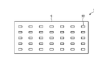
- the non-woven fabric layer 9 has a fixing portion 20 that binds the non-woven fabric fibers to each other by heat welding or an adhesive so as to be united so that the non-woven fabric fibers do not disperse.
- FIG. 5 is a top view schematically showing an example of the configuration of the partition member according to the first embodiment on the non-woven fabric layer side. As shown in FIG. 5, the non-woven fabric layer 9 is provided with a plurality of fixing portions 20.
- the area ratio of the fixing portion 20 to the whole of the non-woven fabric layer 9 contributes to the inhibition of the moisture permeable area.
- the area ratio of the fixing portion 20 to the entire non-woven fabric layer 9 is referred to as the area ratio of the fixing portion 20.
- the difference in moisture permeability between the surface on the moisture permeable resin layer 8 side and the surface on the nonwoven fabric layer 9 side in the partition member 1 It is possible to create. This is because a larger difference in moisture permeability can be created between the surface of the partition member 1 on the moisture permeable resin layer 8 side and the surface on the nonwoven fabric layer 9 side. Further, from the viewpoint of inhibiting the moisture permeation area on the non-woven fabric layer 9 side of the partition member 1, it is desirable that the non-woven fabric material is a hydrophobic resin such as polyester or polypropylene.
- the adhesive area of the nonwoven fabric layer 9 with the moisture permeable resin layer 8 is relatively small. Therefore, the effect of reducing the moisture-permeable area of the moisture-permeable resin layer 8 by the adhesive portion 3 between the nonwoven fabric layer 9 and the moisture-permeable resin layer 8 is smaller than that of the above-mentioned fixing portion 20.
- the adhesive area between the nonwoven fabric layer 9 and the moisture-permeable resin layer 8 it is possible to create a difference in moisture permeability between the surface on the moisture-permeable resin layer 8 side and the surface on the nonwoven fabric layer 9 side. be.
- the moisture-permeable resin layer 8 and the non-woven fabric layer 9 constituting the partition member 1 will be described.
- the moisture permeable resin layer 8 should be made as thin as possible and have as few defects as possible such as pinholes in order to have gas barrier properties. desirable.
- the film thickness of the moisture permeable resin layer 8 is in the range of 5 ⁇ m or more and 30 ⁇ m or less. This is because if the film thickness of the moisture permeable resin layer 8 is less than 5 ⁇ m, the desired gas barrier property may not be obtained, and if the film thickness of the moisture permeable resin layer 8 is thicker than 30 ⁇ m, the desired moisture permeability can be obtained.
- the material of the moisture permeable resin layer 8 is preferably a material that can maintain hydrophilicity, and is any one of hydrophilic polyurethane, polyethylene glycol, styrene sulfonic acid, and sulfonated polyetheretherketone (PEEK). Is desirable.
- the base material layer is a non-woven fabric layer 9 made of a hydrophobic non-woven fabric as described above. If the film thickness of the nonwoven fabric layer 9 is too thin, the mechanical strength at the time of processing cannot be secured, and if it is too thick, the moisture permeability performance of the partition member 1 is impaired. Therefore, the film thickness of the nonwoven fabric layer 9 is in the range of 20 ⁇ m or more and 200 ⁇ m or less. Further, the basis weight of the nonwoven fabric layer 9, that is, the weight of the fiber per unit area [g / m 2 ], has a small difference in in-plane roughness and density from the viewpoint of stability during manufacturing of the partition member 1, that is, the basis weight is as large as possible.
- the basis weight of the non-woven fabric is preferably in the range of 8 g / m 2 or more and 50 g / m 2 or less.
- the gas shielding property of the partition member 1 according to the first embodiment is 5000 seconds / 100 cc or more, preferably 10000 seconds / 100 cc or more in the air permeability resistance measurement by the Gale method or the Oken method as the total heat exchange element 10. be.
- the gas shielding property is in this range, the air is isolated between the air supply air passage 4a and the exhaust air passage 5a, that is, between the air supply and exhaust air, and the ventilation performance can be ensured.
- the heat transfer resistance in the air boundary layer is the main factor in heat exchange between air supply and exhaust, so that the heat transfer property of the material of the partition member 1 is hardly affected.
- the partition member 1 has a two-layer structure of a moisture-permeable resin composite film of the moisture-permeable resin layer 8 and the nonwoven fabric layer 9, but the effect of the first embodiment is exhibited.
- the partition member 1 is not particularly limited to being composed of two resin layers. That is, the partition member 1 may be composed of three or more resin layers.
- the first surface material exposed to the air supply air passage 4a and the second surface member exposed to the exhaust air passage 5a may be made of different materials, more specifically, materials having different moisture permeability.
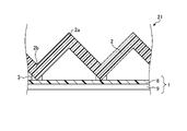
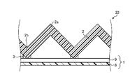
- FIG. 6 are sectional views schematically showing an example of a procedure of a method for manufacturing a total heat exchange element according to the first embodiment.
- two types of single-sided corrugates are produced. One is, as shown in FIG. 6, a first single surface in which one corrugated spacing member 2 is joined to the moisture permeable resin layer 8 side of one partition member 1 by an adhesive portion 3. Corrugated 21. The other is, as shown in FIG.
- a second single-sided corrugate in which one corrugated spacing member 2 is joined to the non-woven fabric layer 9 side of one partition member 1 by an adhesive portion 3. 22.
- the first single-sided corrugated 21 is a member for forming the exhaust air passage 5a
- the second single-sided corrugated 22 is a member for forming the air supply air passage 4a.
- the method for manufacturing a single-sided corrugated board including the first single-sided corrugated board 21 and the second single-sided corrugated board is a step of making a general corrugated cardboard, and a specially processed paper to be a gap holding member 2 is molded into a corrugated shape and the molded gap holding is performed.
- the member 2 is joined to the partition member 1 by the adhesive portion 3.
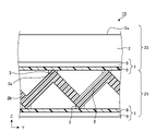
- the extending direction of the ridges 2a and the valleys 2b of the spacing member 2 of the first single-sided corrugated 21 and the ridges 2a and the valleys of the spacing member 2 of the second single-sided corrugated 22 is laminated on the first single-sided corrugated plate 21 so as to be orthogonal to the extending direction of the portion 2b, and both are joined by the adhesive portion 3. Then, the first single-sided corrugated 21 and the second single-sided corrugated 22 are similarly laminated so that the first single-sided corrugated 21 and the second single-sided corrugated 22 alternate in the stacking order.
- the extending direction of the mountain portion 2a and the valley portion 2b of the first single-sided corrugated 21 is the X direction
- the extending direction of the mountain portion 2a and the valley portion 2b of the second single-sided corrugated 22 is the Y direction.
- the first single-sided corrugated 21 and the second single-sided corrugated 22 are laminated.
- the partition member 1 is joined to the mountain portion 2a of the uppermost space holding member 2 by the adhesive portion 3.
- the total heat exchange element 10 is obtained by cutting to a predetermined size.
- the total heat exchange element 10 in which the moisture permeable resin layer 8 is arranged on the exhaust air passage 5a side of the partition member 1 and the non-woven fabric layer 9 is arranged on the air supply air passage 4a side is manufactured.
- a method using an adhesive or a thermal bonding method using no adhesive is used for joining by the adhesive portion 3 between the partition member 1 and the space holding member 2.
- the softening temperature is 130 ° C. or higher, for example, when the nonwoven fabric layer 9 is made of a nonwoven fabric mainly made of polyester, it is preferable to use an adhesive from the viewpoint of the mechanical strength of the total heat exchange element 10.
- the non-woven fabric layer 9 is composed of a non-woven fabric mainly composed of a polypropylene component having a softening temperature of less than 130 ° C., for example, a polypropylene component having a low softening temperature, it is better to bond by heat bonding to realize a bonding with excellent water resistance. It is possible.
- the total heat exchange element 10 for dehumidifying the exhaust flow flowing through the exhaust air passage 5a shown in FIGS. 1 and 2 and humidifying the supply airflow flowing through the supply air passage 4a can be obtained.
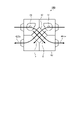
- FIG. 9 is a diagram showing an example of a schematic configuration of the total heat exchange ventilation device according to the first embodiment.
- the total heat exchange ventilation device 100 includes a housing 40, a total heat exchange element 10 according to the first embodiment housed inside the housing 40, a supply air blower 46, and an exhaust blower 47. Inside the housing 40, an air supply flow path 44 for supplying outdoor air to the room and an exhaust flow path 45 for exhausting the indoor air to the outside are provided. At this time, the total heat exchange is such that the supply air passage 4a of the total heat exchange element 10 becomes a part of the supply air flow path 44, and the exhaust air passage 5a becomes a part of the exhaust flow path 45.
- the element 10 is arranged in the housing 40.
- the supply air blower 46 is provided in the supply air flow path 44, and generates an air flow from the outside to the inside of the supply air flow path 44.
- the exhaust blower 47 is provided in the exhaust flow path 45, and generates an air flow from the room to the outside in the exhaust flow path 45.
- the air supply blower 46 and the exhaust blower 47 operate.
- cold and dry outdoor air is passed through the air supply flow path 44 including the air supply air passage 4a as an air supply airflow
- warm and humid indoor air is exhausted as an exhaust flow. It is passed through the exhaust flow path 45 including the air passage 5a.
- the total heat exchange element 10 of the total heat exchange ventilation device 100 two types of airflow, a supply airflow and an exhaust flow, flow across the partition member 1.
- the total heat exchange ventilation device 100 when the total heat exchange ventilation device 100 is operated, the cold and humid outdoor air becomes the air supply air passage 4a.
- the air in the room which is warm and drier than the outdoor air, is passed through the air supply flow path 44 including the exhaust air passage 5a as an exhaust flow.
- the total heat exchange element 10 of the total heat exchange ventilation device 100 two types of airflow, a supply airflow and an exhaust flow, flow across the partition member 1. Heat is transferred between the two types of airflow through the partition member 1, and water vapor permeates through the partition member 1, so that heat exchange of sensible heat and latent heat is performed between the supply airflow and the exhaust flow.
- the surface of the moisture-permeable resin layer 8 on the exhaust air passage 5a side is in contact with air as shown in FIG. 2, and therefore absorbs a large amount of moisture.
- the surface of the moisture permeable resin layer 8 on the air supply air passage 4a side is in contact with air via the non-woven fabric layer 9, and is equal to the area of the fixed portion 20 of the non-woven fabric layer 9.
- the hygroscopic effect on the partition member 1 is reduced.
- the surface near the air on the air supply air passage 4a side that is, the non-woven fabric surface side
- the surface near the air on the exhaust air passage 5a side that is, the surface where the moisture permeable resin layer 8 is exposed, is in a low temperature and high humidity state. Therefore, the sensible heat is exchanged from the air on the supply air passage 4a side to the air on the exhaust air passage 5a side, and the latent heat, that is, the humidity is exchanged from the air on the exhaust air passage 5a side to the air on the supply air passage 4a side. Will be done.
- the total heat exchange ventilation device 100 by ventilating with the total heat exchange ventilation device 100, the loss of cooling / heating efficiency of the indoor air conditioner is suppressed, and the outdoor and indoor air is performed while humidifying the indoor air regardless of the indoor / outdoor air conditions. Can be ventilated. Further, the electric power for exchanging the sensible heat and the latent heat between the supply air passage 4a and the exhaust air passage 5a is not consumed.
- FIG. 10 is a partial vertical cross-sectional view schematically showing another example of the flow path cross section of the exhaust air passage of the total heat exchange element according to the first embodiment.
- the first airflow 6 is an exhaust flow that is the flow of air from the room to the outside of the air conditioner including the total heat exchange element 10
- the second airflow 7 is from the outside to the room of the air conditioner. This is the case when the air supply is the flow of air. That is, the first flow path 4 becomes the exhaust air passage 4b, and the second flow path 5 becomes the supply air air passage 5b.
- the total heat exchange element 10 has a form in which the surface of the non-woven fabric layer 9 of the partition member 1 is exposed to the exhaust air passage 4b which is the first flow path 4, and the second flow.
- Moisture permeability from the supply air passage 5b, which is the passage 5, to the exhaust air passage 4b that is, humidity exchange can be greatly taken. Further, the humidity exchange from the exhaust air passage 4b to the supply air air passage 5b becomes relatively small. As a result, the operation of humidifying the air supply air passage 5b to the exhaust air passage 4b, that is, dehumidifying the air supply airflow flowing through the air supply air passage 5b is realized.
- the room can be dehumidified, contrary to the above example.
- the total heat exchange element 10 arranged in the total heat exchange ventilation device 100 of FIG. 9 has the supply air passage 4a of FIG. 2 becoming the exhaust air passage 4b of FIG. 10 and the exhaust air passage 5a of FIG. It may be replaced and installed so that the air supply air passage 5b in FIG. 10 becomes. That is, the total heat exchange element 10 may be installed in the housing 40 of the total heat exchange ventilation device 100 so that the first flow path 4 becomes the exhaust air passage 4b and the second flow path 5 becomes the supply air air passage 5b. ..
- the total heat exchange element 10 may be rotated by 90 ° in the plane shown in FIG. 9 and installed in the housing 40 of the total heat exchange ventilation device 100. This gives the total heat exchange ventilator 100 capable of ventilating while dehumidifying without using additional power for dehumidification.
- the partition member 1 and the interval holding member 2 for holding the interval between the partition members 1 are provided, and the partition member 1 and the interval holding member 2 are alternately laminated to sandwich the partition member 1.
- a first surface material which is a material of the surface exposed to the first flow path 4 and a second surface which is a material of the surface exposed to the second flow path 5 and is composed of a material different from the first surface material. Made to have the material.
- the moisture permeability of the first surface material and the moisture permeability of the second surface material are different from each other, and therefore, without using electric power for humidification and dehumidification, depending on the indoor and outdoor air environment. It has the effect of being able to humidify or dehumidify the room.
- the total heat exchange ventilator 100 is provided with a humidifying element, and the air supply can be humidified without supplying electric power to the humidifying element. Since it is not necessary to provide a humidifying element, the size of the equipment is suppressed, the installation space is not squeezed, and the living space is not narrowed. In addition, when humidifying, there is no need to supply water, and no separate water charge for humidification is required.
- the function of the partition member 1 described above makes it possible to dehumidify the air supply airflow during the ventilation operation in the normal total heat exchange ventilation device 100 without consuming electric power for dehumidification.
- the total heat exchange element 10 according to the first embodiment is useful for total heat exchange between two types of airflows, and in particular, selectively humidifies or dehumidifies between the supply airflow and the exhaust flow. Can be done.
- the configuration shown in the above embodiment is an example, and can be combined with another known technique, or a part of the configuration may be omitted or changed without departing from the gist. It is possible.
Landscapes
- Engineering & Computer Science (AREA)
- Mechanical Engineering (AREA)
- General Engineering & Computer Science (AREA)
- Physics & Mathematics (AREA)
- Thermal Sciences (AREA)
- Chemical & Material Sciences (AREA)
- Combustion & Propulsion (AREA)
- Heat-Exchange Devices With Radiators And Conduit Assemblies (AREA)
Abstract
Un élément d'échange de chaleur total (10) comporte des éléments de séparation (1) et des éléments de maintien d'espace (2) qui maintiennent des espaces entre les éléments de séparation (1). Les éléments de séparation (1) et les éléments de maintien d'espace (2) sont stratifiés en alternance, et la température et l'humidité sont échangées entre des flux d'air qui s'écoulent à travers des premiers canaux (4) et des seconds canaux (5) qui sont formés par les éléments de séparation (1) et les éléments de maintien d'espace (2) de façon à prendre en sandwich les éléments de séparation (1). Les éléments de séparation (1) comprennent : un premier matériau de surface qui est le matériau se trouvant au niveau de surfaces exposées aux premiers canaux (4); et un second matériau de surface qui est le matériau se trouvant au niveau de surfaces exposées aux seconds canaux (5) et qui est différent du premier matériau de surface.
Priority Applications (1)
| Application Number | Priority Date | Filing Date | Title |
|---|---|---|---|
| PCT/JP2020/046584 WO2022130470A1 (fr) | 2020-12-14 | 2020-12-14 | Élément d'échange de chaleur total et dispositif de ventilation à échange de chaleur total |
Applications Claiming Priority (1)
| Application Number | Priority Date | Filing Date | Title |
|---|---|---|---|
| PCT/JP2020/046584 WO2022130470A1 (fr) | 2020-12-14 | 2020-12-14 | Élément d'échange de chaleur total et dispositif de ventilation à échange de chaleur total |
Publications (1)
| Publication Number | Publication Date |
|---|---|
| WO2022130470A1 true WO2022130470A1 (fr) | 2022-06-23 |
Family
ID=82057431
Family Applications (1)
| Application Number | Title | Priority Date | Filing Date |
|---|---|---|---|
| PCT/JP2020/046584 Ceased WO2022130470A1 (fr) | 2020-12-14 | 2020-12-14 | Élément d'échange de chaleur total et dispositif de ventilation à échange de chaleur total |
Country Status (1)
| Country | Link |
|---|---|
| WO (1) | WO2022130470A1 (fr) |
Citations (7)
| Publication number | Priority date | Publication date | Assignee | Title |
|---|---|---|---|---|
| JP2002228393A (ja) * | 2001-01-31 | 2002-08-14 | Mitsubishi Electric Corp | 熱交換器およびその機能回復方法並びに熱交換換気装置並びに熱交換換気装置のメンテナンスシステム |
| WO2010073762A1 (fr) * | 2008-12-26 | 2010-07-01 | 三菱電機株式会社 | Matériau d'isolation sous vide et boîte d'isolation thermique, réfrigérateur, appareil de conditionnement d'air et de congélation, dispositif d'alimentation en eau chaude, et appareil employant chacun le matériau d'isolation sous vide et procédé de production du matériau d'isolation sous vide |
| WO2011058854A1 (fr) * | 2009-11-11 | 2011-05-19 | 三菱電機株式会社 | Échangeur de chaleur totale et procédé de production de cloison de séparation l'utilisant |
| WO2012018089A1 (fr) * | 2010-08-05 | 2012-02-09 | 日本ゴア株式会社 | Diaphragme et échangeur de chaleur l'utilisant |
| WO2014014099A1 (fr) * | 2012-07-19 | 2014-01-23 | 旭化成せんい株式会社 | Structure multicouche comprenant une couche de cellulose à fibres minces |
| WO2014041746A1 (fr) * | 2012-09-11 | 2014-03-20 | パナソニック株式会社 | Élément de séparation pour un élément d'échange de chaleur total, élément d'échange de chaleur total obtenu à l'aide de l'élément de séparation pour l'élément d'échange de chaleur total et ventilateur de type échange de chaleur |
| WO2020194461A1 (fr) * | 2019-03-25 | 2020-10-01 | 三菱電機株式会社 | Plaque de séparation d'élément d'échange de chaleur totale, élément d'échange de chaleur totale et échangeur de chaleur totale utilisant ledit élément, et procédé de production de plaque de séparation d'élément d'échange de chaleur totale |
-
2020
- 2020-12-14 WO PCT/JP2020/046584 patent/WO2022130470A1/fr not_active Ceased
Patent Citations (7)
| Publication number | Priority date | Publication date | Assignee | Title |
|---|---|---|---|---|
| JP2002228393A (ja) * | 2001-01-31 | 2002-08-14 | Mitsubishi Electric Corp | 熱交換器およびその機能回復方法並びに熱交換換気装置並びに熱交換換気装置のメンテナンスシステム |
| WO2010073762A1 (fr) * | 2008-12-26 | 2010-07-01 | 三菱電機株式会社 | Matériau d'isolation sous vide et boîte d'isolation thermique, réfrigérateur, appareil de conditionnement d'air et de congélation, dispositif d'alimentation en eau chaude, et appareil employant chacun le matériau d'isolation sous vide et procédé de production du matériau d'isolation sous vide |
| WO2011058854A1 (fr) * | 2009-11-11 | 2011-05-19 | 三菱電機株式会社 | Échangeur de chaleur totale et procédé de production de cloison de séparation l'utilisant |
| WO2012018089A1 (fr) * | 2010-08-05 | 2012-02-09 | 日本ゴア株式会社 | Diaphragme et échangeur de chaleur l'utilisant |
| WO2014014099A1 (fr) * | 2012-07-19 | 2014-01-23 | 旭化成せんい株式会社 | Structure multicouche comprenant une couche de cellulose à fibres minces |
| WO2014041746A1 (fr) * | 2012-09-11 | 2014-03-20 | パナソニック株式会社 | Élément de séparation pour un élément d'échange de chaleur total, élément d'échange de chaleur total obtenu à l'aide de l'élément de séparation pour l'élément d'échange de chaleur total et ventilateur de type échange de chaleur |
| WO2020194461A1 (fr) * | 2019-03-25 | 2020-10-01 | 三菱電機株式会社 | Plaque de séparation d'élément d'échange de chaleur totale, élément d'échange de chaleur totale et échangeur de chaleur totale utilisant ledit élément, et procédé de production de plaque de séparation d'élément d'échange de chaleur totale |
Similar Documents
| Publication | Publication Date | Title |
|---|---|---|
| US8235093B2 (en) | Flat plate heat and moisture exchanger | |
| US20140262125A1 (en) | Energy exchange assembly with microporous membrane | |
| EP2250446B1 (fr) | Refroidisseur par évaporation | |
| US8550151B2 (en) | Heat exchanger | |
| JP2639303B2 (ja) | 全熱交換器 | |
| US9404689B2 (en) | Heat exchange matrix | |
| JP6833106B2 (ja) | 全熱交換素子および全熱交換器 | |
| JP5987854B2 (ja) | 熱交換素子及び熱交換器 | |
| JP2013015286A (ja) | 全熱交換器及びこれに用いる仕切板の製造方法 | |
| JP4341924B2 (ja) | デシカント換気システム | |
| JPH09280765A (ja) | 熱交換エレメント | |
| JP2020139650A (ja) | 熱交換素子及びそれを用いた熱交換形換気装置 | |
| KR102144961B1 (ko) | 열회수형 환기시스템의 전열교환소자 | |
| JP2006068727A (ja) | 除湿装置 | |
| JP6262445B2 (ja) | 水蒸気選択透過膜を使用する全熱交換器 | |
| JP2009144930A (ja) | 全熱交換器 | |
| JP7569240B2 (ja) | 住宅 | |
| JP7190817B2 (ja) | 水分移動ユニット | |
| JP4622660B2 (ja) | 吸着素子 | |
| WO2023223455A1 (fr) | Élément d'échange de chaleur total, échangeur de chaleur total et procédé de production d'élément d'échange de chaleur total | |
| JP2022083366A (ja) | 全熱交換型コンタミレス換気ユニット | |
| JP2023065737A (ja) | 熱交換形換気装置 | |
| JP2011102688A (ja) | 熱交換器及び除湿空気調和装置 | |
| JPH0634899B2 (ja) | 水蒸気選択透過膜 | |
| JP2004225957A (ja) | 加湿シート及び加湿器並びに換気装置 |
Legal Events
| Date | Code | Title | Description |
|---|---|---|---|
| 121 | Ep: the epo has been informed by wipo that ep was designated in this application |
Ref document number: 20965858 Country of ref document: EP Kind code of ref document: A1 |
|
| NENP | Non-entry into the national phase |
Ref country code: DE |
|
| 122 | Ep: pct application non-entry in european phase |
Ref document number: 20965858 Country of ref document: EP Kind code of ref document: A1 |
|
| NENP | Non-entry into the national phase |
Ref country code: JP |